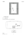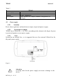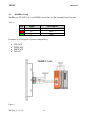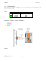
1
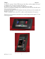
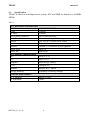
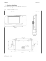
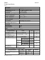
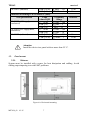
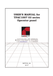
USER’S MANUAL TP1043 series ME7029_02 03/15 TP1043 mect srl INDEX 1. Introduction ................................................................................................................................... 1 1.1. Staff skill ................................................................................................................................. 1 1.2. Simbols ................................................................................................................................... 1 1.3. Terms ...................................................................................................................................... 2 1.4. Security ................................................................................................................................... 2 1.5. REFERENCE MANUAL ....................................................................................................... 2 2. System description ........................................................................................................................ 2 2.1. Specification ........................................................................................................................... 4 3. Hardware Installation .................................................................................................................... 5 3.1. Mechanical dimensions .......................................................................................................... 5 3.2. Panel mount ............................................................................................................................ 7 3.2.1. Distance ............................................................................................................................ 7 4. TP1043 wiring ............................................................................................................................... 8 4.1. Connections ............................................................................................................................ 8 4.2. Power supply .......................................................................................................................... 9 4.2.1. Isolation ............................................................................................................................ 9 4.2.2. System power supply ....................................................................................................... 9 4.2.3. Fuse .................................................................................................................................. 9 4.3. ModBus wiring ..................................................................................................................... 10 4.4. CANOpen wiring .................................................................................................................. 11 5. Peripherals ................................................................................................................................... 12 5.1. USB....................................................................................................................................... 12 5.2. Ethernet ................................................................................................................................. 12 6. HMI ............................................................................................................................................. 12 6.1. System variables ................................................................................................................... 12 7. How to order ................................................................................................................................ 12 ME7029_02 03/15 TP1043 mect srl 1. Introduction To grant a fast setup of the device please follow carefully the information in this manual. 1.1. Staff skill Products described in this manual are devoted to PLC programmers or automation experts only. MECT S.r.l. declines any responsibility about malfunctioning or damage caused by incorrect use of MECT devices, due to noncompliance to this manual information. MECT S.r.l has an help desk. 1.2. Simbols Danger Follow this advice to avoid people injury. Warning Follow this advice to protect the device. Caution Follow this advice to have a more effective performance. ESD ( Electrostatic discharge) Danger: possibly damage due to Electrostatic discharge. Note Step to follow for a correct installation. Additional information ME7029_02 03/15 1 TP1043 mect srl 1.3. Terms PLC: Terminals: System: 1.4. TP1043 TPLC005, MPNC010, MPNC020, MPNC030 PLC (TP1043) with terminals Security Attention Switch off devices before connecting them. ESD (Electrostatic discharge) Modules have electronic components that can be damaged by. electrostatic discharge. Be sure to be connected to ground when handle the devices. The instrument has no power switch and no internal fuse, but it powers on immediately after connecting a correct power supply input (check the power supply value on the instrument label). Keep the power supply line as short as possible and keep it separate from other power lines. For security reasons it is necessary to have a 2 section power switch with a fuse near the instrument and easily replaceable. Avoid the presence of other power actuators in the same control panel, high humidity, excessive heat and corrosive gas. Instruments must have a power supply from security transformers or SELV transformers. 1.5. REFERENCE MANUAL Quick Start Qt Mect Configurator 2. System description TP1043 is a device composed by a PLC and a HMI with touch-screen monitor 4.3” width and 480 x 272 pixel resolution with 262.000 colors. TP1043 allows the supervision of networked devices Modbus RTU and Modbus TCP. The networks are managed simultaneously by TP1043 and data from a network can be sent on another thus creating a bridge between the two networks. ME7029_02 03/15 2 TP1043 mect srl On TP1043 is present Micro-USB host port, that allows, with an adapter, the use of an USB-pen drive for software updates and data log. On TP1043 are up to 1 Kbyte of retentive variables stored on flash. The device is also able to manage an up to 8GB wide, micro SD card. The SD card is factory mounted on request. A real-time clock buffered RAM maintains the date and time up to four months with the device turned off. TP1043 is equipped with a micro PLC to make a small automation of the process. The device can be applied in horizontal or in vertical design with the option "V" (see following pictures). Figure 1: Front view TP1007 (horizontal version) Figure 2: Front view TP1007 (vertical version) ME7029_02 03/15 3 TP1043 mect srl 2.1. Specification TP1043 is based on a multiprocessor system. PLC and HMI are based on a 454MHz ARM9. Table 1 PLC Hardware characteristics PLC Processor RAM FLASH Non volatile variables Real Time Clock Screen Touch screen Ethernet Micro-USB Micro SD PLC software characteristics OS PLC Graphics CAN ModBus Storage memory LINUX 2.35 IEC61131-3 Based on QT library CanOpen 2.0 Modbus RTU master Possibility of history storage Field bus main features RTU Modbus TCP Modbus Master 2 wires Client ME7029_02 03/15 ARM926JE 454MHz 128MB 128MB On FLASH memory Yes with rechargeable battery TFT 480 x 272 pixel 262k colors Resistive 4 wires 10Mbit/s - 100Mbit/s self recognition Host 2.0 Max 8GB 4 TP1043 mect srl 3. Hardware Installation In the following figures see the TP1043 dimensions. 3.1. Mechanical dimensions Side view Rear view Figure 3 Figure 4 Side view Figure 5 ME7029_02 03/15 5 TP1043 Technical specification mect srl Table 2 Mechanical Material ABS, Polycarbonate 27.7 mm x 159 mm x 83 mm Dimensions W x L x H Mounting plate 127mm x 68mm Installation Panel installation Environmental conditions Operative temperature 0 °C ... 55 °C Storage Temperature -20 °C ... +85 °C Relative Humidity 5 % a 95 % no condensation Electric isolation Air clearance According to IEC 60664-1 Pollution 2 According to IEC 61131-2 Protection Rear protection IP 20 Front protection IP65 EMC EMC according to EN 61000-6-2 (2001) Test specification Values Class EN 61000-4-2 ESD EN 61000-4-3 electromagnetic fields EN 61000-4-4 burst EN 61000-4-5 surge 4 kV/8 kV (contact/air) 10 V/m 80 MHz ... 1 GHz Criterion 2/3 3 B A 1 kV/2 kV (data/supply) 2/3 Data: -/- (line/line) 1 kV (line/earth) 2 DC 0.5 kV (line/line) 1 supply: 0.5 kV (line/earth) 1 AC 1 kV (line/line) 2 supply: 2 kV (line/earth) 3 EN 61000-4-6 10 V/m 80 % AM (0.15 ... 80 3 RF disturbances MHz) Emissions according to EN 61000-6-4 (2001) Test specification Limit Frequency values/IQPI Range EN 55011 (AC supply, 79 dB (µV) 150 kHz ... 500 conducted) 73 dB (µV) 500 kHz ... 30 MHz ME7029_02 03/15 B B 6 B B A Distance TP1043 mect srl EN 55011 (radiated) 40 dB (µV/m) 47 dB (µV/m) Emissions according to EN 61000-6-3 (2001) Test specification Limit values/IQPI EN 55022 (AC supply, 66 ... 56 dB conducted) (µV) 56 dB (µV) 60 dB (µV) EN 55022 (DC supply/data, 40 ... 30 dB conducted) (µA) 30 dB (µA) EN 55022 (radiated) 30 dB (µV/m) 37 dB (µV/m) 30 MHz ... 230 MHzMHz ... 1 230 GHz Frequency Range 150 kHz ... 500 kHz 500 kHz ... 5 MHz 5 MHz ... 30 MHzkHz ... 500 150 kHz 500 kHz ... 30 MHz 30 MHz ... 230 MHz 230 MHz ... 1 GHz 10 m 10 m Distance 10 m 10 m Attention Install the device in a panel with no more than 55 °C. 3.2. Panel mount 3.2.1. Distance System must be installed with a space for heat dissipation and cabling. Avoid cabling superimposing to avoid EMC problems. Figure 6A: Horizontal mounting ME7029_02 03/15 7 TP1043 mect srl Figure 6B: Vertical mounting 4. TP1043 wiring 4.1. Connections In the following figure see the wiring diagram. Figure 7 ME7029_02 03/15 8 TP1043 mect srl Table 3 TP1043 Power Supply Micro-USB Ethernet Serial ouputs 4.2. 24Vdc/Vac -10 /+20% 250mA (24Vdc) 2.0 Bit rate: 100Mbit/sec RS485 Modbus half duplex (hardware configuration) or CANopen Power supply 4.2.1. Isolation Device has no galvanic isolation between input, output and power supply. 4.2.2. System power supply TP1043 has a 24Vdc/Vac 20%) according to the scheme in the figure. System is protected against reverse power supply. 4.2.3. Fuse System has no internal fuse , so is suggested the use of an external 500mA fuse for the panel power supply. Figure 8 Attention A wrong value for the power supply can cause a damage to the device ME7029_02 03/15 9 TP1043 mect srl 4.3. ModBus wiring ModBus on TP1043 is a 2 wire RS485 serial line, on the terminal board on pins: Table 4 Pin 3 2 1 Signal GND D+ D- Description Linea + Linea - Example of a wiring of a system composed by: TPLC005 MPNC020 MPNC030 TP1043 Figure 9 ME7029_02 03/15 10 TP1043 mect srl 4.4. CANOpen wiring The CANopen interface on TP1043 must be connected to the terminal block on the pins shown in the table. Table 5 Pin 3 2 1 Signal GND CAN L CAN H Description Linea Linea + Example of a wiring of a system composed by: MPNC010 MPNC030 TP1043 Figure 10 ME7029_02 03/15 11 TP1043 5. Peripherals mect srl 5.1. USB TP1043 has a Micro-USB 2.0 host for: software update data storage: datalogger connect USB peripherals as printers, mouse, etc. Specific connection of external peripherals are implemented on request. 5.2. Ethernet TP1043 has a 10/100Mbit/s ethernet port with auto-configuration, moreover the connection cable between TP1043 and a personal computer can be either straight either cross. 6. HMI To set the TP1043 is necessary to develop a software in QT Creator based on QT libraries, custom-tailored on MECT operator panel. A specific tutorial is furnished with the device. The QT Creator suite software is available in Windows environment. 6.1. System variables The system can use 5472 interchange variables between HMI and automation (at maximum) which include: internal variables, interchange variables on Modbus network, retentive variables. The variables are defined by a tool furnished from Mect. 7. How to order ME7029_02 03/15 12