1
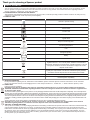
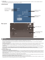
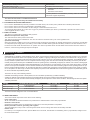
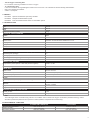
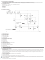
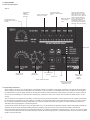
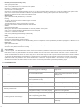
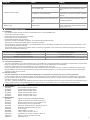
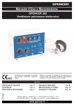
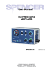
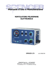
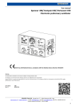
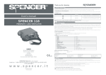
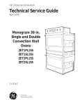
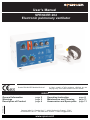
User's Manual
SPENCER 202
Electronic pulmonary ventilator
This appliance conforms with the
Directive 93/42/CEE "Medical Devices".
Guarantee of Quality system for the production and
the final control of the products certified by the
notifying body TÜV SÜD Product Service GmbH.
INDEX
First edition 1998
REV. 11 26/06/13
General Information
Warnings
Description of Product
page 2
page 3
page 4
Operating Instruction
Maintenance and Cleaning
Accessories and Spare parts
Spencer Italia S.r.l. Strada Cavi, 7 - 43044 Collecchio (Parma) - ITALY
tel. 0039 0521 541111 - fax 0039 0521 541222 - e-mail: [email protected]
www.spencer.it
page 6
page 11
page 11
Thank you for choosing a Spencer product
1 GENERAL INFORMATION
1.1 AIM AND CONTENTS
The aim of this manual is to supply all the information necessary so that the client, will not only attain adequate use of the appliance, he will
also be capable of using the instrument in the most autonomous and secure way possible. This includes information regarding technical
aspects, functioning, maintenance, spare parts and safety.
1.2 CONSERVATION OF THE INSTRUCTION MANUAL
The instruction and maintenance manual must be kept with the product, inside the specially provided container and above all, away from any
substances or liquids which could compromise perfect legibility.
1.3 SYMBOLS USED
SYMBOL
MEANING
General or specific warning
See instructions for use
Serial number
Product code
The product is compliant with the specifications of the Directive 93/42/CEE
Type B device
Keep in a cool and dry place
Functioning temperature
Fuse
Storage temperature
Battery
Device with isolation class II
Information to the users in compliancy with comma 13 of the Italian
Legislative Decree n. 151 of 25 July 2005, "Fulfilment of the Directives
2002/95/CE, 2002/96/CE and 2003/108/CE, regarding Reduction of the use
of dangerous substances in electric and electronic equipments and the
disposal of their wastes”
Information for end user as indicated in Art. 22 of the Law Decree n. 188 20/11/08
regarding the "implementation of the Directive 2006/66/CE regarding batteries,
accumulators and their disposal which annuls the Directive 91/157/CEE"
IP22
Grade of protection IP22
EMC
Electromagnetic compatibility
1.4 SERVICING REQUESTS
For any information regarding the use, maintenance and installation, please contact the Spencer Customer Care Service on tel. 0039 0521
541111, fax 0039 0521 541222, e-mail [email protected] or write to Spencer Italia S.r.l. - Strada Cavi, 7 - 43044 Collecchio (Parma) - ITALY.
1.5 DEMOLITION
Follow the current regulations.
Information to the users in compliancy with comma 13 of the Italian Legislative Decree n. 151 of 25 July 2005, "Fulfilment of the Directives
2002/95/CE, 2002/96/CE and 2003/108/CE, regarding Reduction of the use of dangerous substances in electric and electronic equipments and
the disposal of their wastes.
The crossed dustbin symbol applied on the product or on it's packaging indicates that the item should be disposed of separately. The correct disposal of
the item when use has terminated, is defined and organised by the manufacturer. The end user who has to proceed with disposal, must therefore contact
the manufacturer and follow the system and procedures the manufacturer has organised for the separate collection, treatment and disposal at end-of-life.
The correct separate collection of the out of use device which will permit recycling, treatment and destruction in an ecologically friendly manner and will
contribute to avoiding possible negative effects on the environment and for health while privileging the reuse and/or recycling of the collected waste components.
Please note that the owner will be subject to administrative sanctions in case of unauthorised disposal of the item.
Information for end user as indicated in Art. 22 of the Law Decree n. 188 20/11/08 regarding the "implementation of the Directive
2006/66/CE regarding batteries, accumulators and their disposal which annuls the Directive 91/157/CEE"
DISPOSAL OF WASTE BATTERIES
This symbol on the battery or on the packaging indicates that the battery provided with this product shall not be treated as household waste. By
ensuring these batteries are disposed of correctly, you will help prevent potentially negative consequences for the environment and human
health which could otherwise be caused by inappropriate waste handling of the battery. The recycling of the materials will help to conserve natural resources. At the end of their life hand the batteries over to the applicable collection points for the recycling of waste batteries. For more
detailed information about recycling of this product or battery, please contact your local Civic Office, your household waste disposal service or
the shop where you purchased the product.
2
1.6 LABELLING
The serial number as indicated below can be found on each appliance and must not be removed or covered. In order to facilitate assistance
please indicate or communicate the serial number (SN) on the label.
Lateral panel
Fuse identification
Medical gas output
identification
Feeding connector
identification
Medical gas input
identification
Fig. A
Rear panel
Alarm battery 9 V
Rechargeable battery
12 V 2-2.3 AH
Fig. B
2 WARNINGS
2.1 GENERAL WARNING
• Before carrying out any kind of operation on the appliance, the operator must carefully read the enclosed instructions, paying particular attention to
the correct safety precautions and to the procedures to be followed for installation and for correct use.
• In the case of any doubts as to the correct interpretation of the instructions, please contact Spencer Italia S.r.l. for any necessary clarifications.
• Regularly check the appliance.
• In the case of any abnormalities or damage to the appliance, which could jeopardize the functioning and the safety, the appliance must be immediately removed from service.
• Do not alter or modify in any way the appliance; any such interference could cause malfunctions and injury to the patient and/or rescuer.
• The appliance must not in any way be tampered with. In such cases all responsibility will be denied for any malfunctions or injuries caused by the
appliance itself.
• Those who modify or have modified, prepare or have prepared medical appliances in such a way that they no longer serve the purpose for which they
were intended, or no longer supply the intended service, must satisfy the valid conditions for the introduction onto the market.
• Ensure that all the necessary precautions are taken in order to avoid the hazards that can arise as the result of contact with blood or body fluids.
• Handle with care.
2.2 SPECIFIC WARNINGS
• The product must be used by trained personnel only.
• If any failure or incorrect functioning of the device is detected, it must be immediately substituted with a similar item so that the rescue procedures are
guaranteed without any interruption. If another lung ventilator is not available, ventilation must be immediately re-established manually (ex. Spencer
B-life manual resuscitation bag) in order to maintain vital life support. If necessary they can be used with a PEEP valve and reservoir bag for the enrichment with oxygen.
• When the device is being used, the assistance of qualified staff must be guaranteed.
• The device has seals. If they have been removed or tampered with the manufacturer declines any responsibility for the product and for its correct functioning and for any consequent damage that may occur to the device.
• Before turning on the pulmonary ventilator, the battery must be put under charge for at least 12 hours.
• The use of the device with power source and environmental conditions different from those indicated compromises the safety of operating. In the following table are some of the abnormalities that could occur under these conditions:
3
CONDITIONS
Excessive power feeding current
Low power feeding current
Excessive environmental temperature
Low environmental temperature
•
•
POSSIBLE PROBLEM
The fuse burns
The battery does not recharge
• Problems with the sealing membranes
• Gas leaks
• Excursions of the set flow
Possible presence of condensation (occurring when the ventilator is
returned to a higher temperature)
The device must be used in a ventilated environment.
A minimum of charge must always be maintained in the battery.
2.3 CONTRAINDICATIONS AND SIDE EFFECTS
Do not use the SPENCER 202 pulmonary ventilator in neonatal clinics (0-18 months) and in patients with un drained pneumothorax.
Do not use the device in presence of inflammable or anaesthetic gases.
Do not use the device if it is connected to an SPS charger or other transformer 220 V/12 V.
To avoid hypercapmia effects do not use 100% oxygen for protracted ventilation (the device is provided with a special mixer switch to select
mixed oxygen/air at 60% or 100%).
2.4 SAFETY SYSTEMS
The device is provided with the following safety systems:
• Mechanical overpressure safety valve
The maximum limit of device pressure is 60 mbar.
This value is imposed by the manufacturer. The user can reach the maximum level by use of the regulation knob.
• Spontaneous breathing
When the pulmonary ventilator is off or gas or electrical supply is interrupted, the patient can breathe spontaneously. The device is provided with
an independent power supply alarm (9 V battery). This acoustic and visible alarm signals the low battery condition. This alarm functions even if
the device is turned off with the switch in the "O" position. The device is provided with an acoustic alarm which functions when the machine is
turned on, if the incoming medical gas input is interrupted.
•
•
•
•
3
DESCRIPTION OF PRODUCT
3.1 INTENDED USE
SPENCER 202 is a breathing control/assistance device, which comprehends the emerging trends in the field of automatic respirators. It is a volumetric
type device with electrical control of the respiratory functions, capable of supplying medical gas at two different concentrations with a single gas source, complete with mechanical and electronic safety devices which supervise over some of the principal respiratory parameters. The SPENCER 202 pulmonary ventilator is portable with a two-hour self-powered electric energy system: after two hours external power feeding is necessary, this will automatically recharge the internal system. SPENCER 202 has two operating modes, automatically changed by the software, and a series of warning lights
connected to an audible signal which permits rapid identification of any dysfunctions. The user interface is in the front control panel made in a material
which is scratch proof and resistant to common medical substances The front panel has clear and intuitive graphics and the operating buttons are protected to avoid accidental functioning. On the right hand side there is a flange with connections for the pressurised oxygen and the supply of medical
mix for the patient. The wide range of volumes and respiratory frequencies of the SPENCER 202 and the monitoring system for patient safety permits
its use for both adult and paediatric patients.
•
•
The device can carry out the following functions:
Substitute the breathing functions in those patients, who do not breathe spontaneously (controlled ventilation).
Assist those patients whose breathing functions are irregularly altered and anyway insufficient (automatic breathing system).
The switch from one mode to another is automatically managed by the microprocessor under certain conditions. The following list shows the optimal
ventilation parameters:
PATIENT
Adult
Child up to 15 kg
Child over 15 kg
RESPIRATORY FREQUENCY (RF)
10-20 breaths/min
40 breaths/min
30-35 breaths/min
TIDAL VOLUME (TV)
MINUTE VOLUME (MV)
10-12 ml/kg
10-15 ml/kg
10-15 ml/kg
TV x RF
TV x RF
TV x RF
The device has been designed for use on road ambulances.
3.2 MAIN COMPONENTS
The main functional components of the device are the following:
• Front control panel
All the commands and functional selectors are positioned here. Manufactured in anti scratch polycarbonate.
• Electronic control board
Operates the integrated control of all respiratory functions and of the main parameters of respiration.
• Electro-pneumatic circuit for gas mixing and erogation
The pressurised gas in entry is sent to the mixing block thanks to a flow cutting valve that is electronically controlled.
• Patient circuit
It is made up of a corrugated PVC tube, Spencer Mask size 4 face mask, autoclavable non-rebreathing valve in polycarbonate, straight connector and anti batteric filter.
4
•
•
-
100 cm Oxygen connecting tube
For connection of the lung ventilator to a source of oxygen.
12 V Connecting cable
It can be connected to the cigarette lighter socket for the 12V source or to a transformer with the following characteristics:
inlet source 220/230 Vac 50/60Hz
outlet 4 V 0,8 Ampere
3.3 MODELS
EV01202A
EV02202A
EV60202A
Spencer 202 Electronic pulmonary ventilator
Kompak 202 Resuscitation system
Porta Vent 202 Rucksack version of resuscitation system
3.4 TECHNICAL DATA
DIMENSIONS
Width
Height
Depth
Weight (accessories included)
TECHNICAL CHARACTERISTICS
Isolation
Grade of protection
class II
IP22
ELECTRIC VALUES
Electric source
Charging tension
Absorption of current
Absorption of current at 12 Vdc
connection to external tension stabilised at 12 Vdc
maximum 14 V
maximum 249 mA
2.98 W
330 mm
180 mm
175 mm
3,5 kg
FUSES
External powered 12 V
1A
INTERNAL BATTERY (must never be completely flat!)
Functioning time (average)
Recharging time
Functioning time after signalling of low battery
Internal volume of the patient circuit tubes
2h
12 h
5 min
351 cm3
MEDICAL GAS (OXYGEN)
Input pressure (central system or tank with pressure regulator)
3,5 bar ± 0,5 bar
Minimum capacity
140 L/min
VENTILATION
Minute volume
Volume delivered (measurable)
Ventilation Frequency
Oxygen concentration
I:E Ratio
Pressure (sub-atmospheric) negative in the exhaling phase
from 2 to 20 L/min
(volume/minutes):frequency
from 5 to 40 BpM
60% or 100%
1/2
Not available
MANOVACCUUMETER
Tolerance
Range from -20 to +10 mbar
Range from +10 to +70 mbar
MAXIMUM DEVIATION OF SET VALUES
da -20 a +70 mbar
2 mbar
5 mbar
Medical gas flow
Frequency
± 15%
± 1 BpM
Note:
The medical gas flow is not influenced by pressure. The ventilator does not monitor the oxygen concentration (mechanical mixing). Unless
otherwise specified the parameters are expressed in ATPD (Ambient, Temperature and Pressure Dry).
3.5 ENVIRONMENTAL CONDITIONS
Environmental temperature
Relative humidity
Atmosferic pressure
STORAGE AND TRANSPORT
from -10 to +60 °C
from 10 to 100%
from 50 to 106 kPa
FUNCTIONING
from 0 to +40 °C
from 15 to 95%
from 70 to 110 kPa
5
3.6 ELECTROMAGNETIC ENVIRONMENT
The SPENCER 202 pulmonary ventilator is created to operate correctly in an electromagnetic environment. It has successfully passed all the
electromagnetic tests stipulated in Harmonised Standards by the Notifying Body (see Declaration of Conformity).
3.7 STANDARDS APPLIED
• EN 60601-1+ A1 + A2 + A12 +A13 + corrigenda (July 1994)
• IEC 601-1-2 (EN 60601-1-2)
• EN 794-3
• 89/336/CEE
• 92/31/CEE
3.8 PNEUMATIC DRAWING
Gas mixer with
Venturi
Inside equipment
Fig. C
1.
2.
3.
4.
5.
6.
7.
8.
9.
10.
11.
12.
13.
14.
15.
16.
17.
High pressure source
High pressure gauge
High pressure adapter
Quick coupling input
Low pressure adapter
Pressure switch
Electrovalve with 2 N.C. outputs
Flow regulator with fixed capacity
Venturi system
No-return valve
Aspiration air filter
Capacity selection knob
Overpressure release with no-return valve
Overpressure release valve
Low pressure erogation manometer
Pressure switch
Outlet with no-return valve
4
OPERATING INSTRUCTIONS
4.1 TRANSPORT AND STORAGE
Before transporting the appliance, make sure that it is correctly packaged ensuring also that there are no risks of shocks, bumps or falls during
the transport itself.
Keep the original packaging for use in case of any further transport. Damage to the appliance caused during transport and handling is not covered by the guarantee. Repairs or replacement of the damaged parts are the responsibility of the client. The appliance must be stored in a dry
place free from humidity.
In case of prolonged periods of inactivity or before transportation:
1. Switch is in off position "O".
2. Unplug the power lead.
3. Check the charge status of the internal battery and re-charge it, if necessary.
In case of long inactivity, in addition to these recommendations, the device must be stored with the precautions relevant to the place
and time of stocking:
• Store the pulmonary ventilator in a closed place.
6
•
•
•
Keep it from stress and impacts.
Protect it from humidity as well as excessive thermal excursions.
Avoid contact with corrosive substances.
4.2 PREPARATION
On receipt of the product:
• Remove the packaging and display the material so that all components are visible.
• Check that all the components/pieces on the accompanying list are present.
The appliance must be checked before every use so as to reveal any working abnormalities and/or damage caused by transport and/or storage.
• Put the pulmonary ventilator on a flat surface (i.e. shelf, trolley).
• If used on an ambulance, the device must be fixed correctly, using the purpose made threaded holes, with diameter 6 threaded screws.
• It is possible to fix the pulmonary ventilator on a rail with the purpose made hooks.
The operations of preparation listed below must be carried out and checked before every use.
To check
RESPIRATORY SYSTEM
ELECTRIC POWER SUPPLY
Result required
•
•
•
•
•
•
•
Corrugated tube
Non-rebreathing valve
Overpressure test
Face mask
Ventilation test
Anti batteric filter
Straight connector
•
•
All components must be intact and correctly connected
See paragraph 4.5.2 "Operating instructions"
•
Press on switch "I"
•
The respirator ventilates
Ensure the availability of a mechanical/manual ventilation system (i.e. resuscitation bag Spencer B-life). Before using the device check the
correct functioning of the alarm LED by applying pressure (at least 2 sec) on the acoustic turnoff button. During the test the LED lights up and
the buzzer will sound.
The device must be used in a ventilated environment.
4.3 ELECTRIC SOURCE
4.3.1 Control of alarms battery 9 V
The 9 V alarms battery should be regularly checked or replaced depending on its use. Through digital tester, verify that the voltage of the 9 V
battery is not lower than 10%. The correct polarity for the reintegration of the 9 V battery is guaranteed by the seat of the battery holder and
symbols indicated. For older versions Kompak and Porta Vent exercise care and reassemble the fan frame without excessive force on the rear
M6 allen.
4.3.2 First charge of the internal battery
The SPENCER 202 pulmonary ventilator is powered by a rechargeable battery. A new battery is never completely charged. It will be charged
completely only if left under charge it for 24 hours non stop before first use. The battery, recharges automatically during normal functioning of
the device connected to the 12 Vdc source or with 220 V transformer.
With a fully charged battery in good condition, the ventilator can function for about two hours. With low batteries or battery in bad
condition it may function for a shorter time.
If the device remains unused for over 3 months, the battery must be recharged. The device must not be left under charging for more
than the time indicated. If the battery is allowed to become flat and/or if the device is left attached to the source the life of the battery
will be considerably reduced.
4.3.3 External 12 Vdc source
An external source may be used in emergency situations or during the use of the ventilator on ambulances and/or helicopters. Use only electric
connection cable code EV20010A. The free end of the cable must be correctly connected with the direct current plug.
Connection specifications
Red or brown wire
White wire
Shielding
on + (positive pole)
on - (negative pole)
on - (negative pole)
Insert the connector on the ventilator side.
The device indicates the connection with the net through the "Ext. source" LED.
4.3.4 Emergency electrical feeding through a supplementary battery
Do not put the spare battery on the device. It must be placed as far as possible from the inlet air filter of the ventilator.
4.4 FEEDING COMPRESSED GAS
Use oxygen (central system or oxygen tank with pressure regulator) or compressed medical air with an entrance pressure from 3,5 bar ± 0,5 bar
and a minimum capacity of 140 L/min.
7
4.5 FUNCTIONING
4.5.1 Front control panel
Fig. D
NO AIR MIX /
AIR MIX
switch with
protection
Trigger selection knob
(from 0 to -12 mbar)
Manovacuumeter luminous
LED:composed of 21 LED in
green colour and 3 in yellow
colour (which turn on when the
pressure reaches 60-65-70
Maximum pressure mbar, a value which requires
the operator's attention).
alarm selection
Visualises the values of miniknob
mum and maximum pressure
and trigger set by the operator.
Low pressure alarm
selection or disconnection
knob
Airway-pressure limit
selection knob, from 20 to
60 mbar
Alarms LED
Minute volume
selection knob
Frequency
selection knob
OFF switch (hold
for 3 sec)
Colour code
ON
Alarms management button
LED for battery
condition and
feeding
screening
Exclusion of the acoustic
alarm (LED test with
pressure for 2 sec)
4.5.2 Operating instructions
When turning on the device, the microprocessor automatically switches the ventilator to the default "controlled" mode and checks the acoustic
alarm inhibiting it for about 30 seconds detailing any information on the front panel in the dedicated alarm section. Erogation of medical gas to
the patient starts in cycles at regular intervals in correspondence with the relevant frequency selected by the command. The current volume of
mix sent to each breathing act is detected in the following way: read the set value on the "minute volume" button and divide it by the set "frequency".
The real pressure of the patient circuit is always monitored by the luminous manovacuumeter on the front panel. For the duration of functioning,
the microprocessor regulates the cyclical erogation of medical gas and verifies the state of some parameters of breathing, moreover it signals
the exceeding of safety limits activating, depending on the case, the acoustic and/or luminous signals. The different functioning modes are
described in the next paragraph 5.3 "Functioning modes".
Apnoea will be detected by the device only if the patient after one or more spontaneous inspirations (situation which automatically activates the
"assisted" functional mode), interrupts breathing during the breathing cycle (8 seconds). In this case the lung ventilator activates the
luminous/acoustic signal of apnoea and commutes automatically in "controlled" (erogated mix at fixed frequency), it turns on the luminous signal
of apnoea. Should the patient start to breathe naturally the device will automatically go back to "assisted/controlled" mode and cancel any alarm
signals, which are still active.
8
•
•
It is essential to regulate first the ventilator volume and then pressure because if the volume was to be regulated after the pressure it
would cause an immediate change of the pressure limit. After choosing volume ventilation, use the palm of the hand to keep the
outlet of the patient valve (where the mask normally is attached) and then regulate the pressure limit with the knob.
Hyperextend the head and check the passage of the air by inserting an oral-pharynx cannula (or Guedel cannula) in the patient's
mouth with the usual manoeuvre. Place the ventilation mask on the mouth and on the nose of the patient checking the adhesion of
the soft part of the mask on the patient's face for a tight fitting. Selection method of the minute volume knob (step selector) prevents
undesired value changing during functioning in case of accidental touch.
If the patient is intubated, remove the ventilation mask of the patient valve. Insert the free adapter the endotracheal tube with its own connector.
Resistance of the patient airways due to obstructions or to external cardiac massage do not involve a frequency and respiratory volume modification. In case of lung compliance reduction, the ventilator reacts with an increase of the respiratory pressure at a constant volume.
When use of the SPENCER 202 terminates it is necessary to:
Press the off button "O" (for 2 seconds)
Interrupt oxygen supply by closing the valve on the oxygen tank or by disconnecting the oxygen tube connection
4.5.3 Functioning modes
• Assisted/controlled ventilation
Start halfway through the exhaling phase it extends for the duration of the whole exhaling phase. Any attempt of the patient to inhale sufficient
amounts of product in this interval determines the start of a new breathing act and the consequent delivery of medical gas flow. Attempts to
inspire made outside this interval are not accepted: anticipated attempts because they could be caused by transitional situations in the patient
circuit and could simulate voluntary breathing; late attempts as they could not show, since the machine switches automatically to controlled
mode if the maximum limiter of wait is exceeded, thus inhibiting any attempt to inhale except for the final part of the exhaling phase.
In case of exceeded maximum pause period, the apnoea situation is signalled visually and acoustically. The alarm remains active until acceptance on the part of the respirator of an attempted inhalation valid as from the patient or until the alarm cancelling button "Reset alarms" is pressed.
This functioning mode guarantees prompt intervention of the machine in case spontaneous breathing of the patient stops but also allows for an
easy adaptation of the patient as it permits variations in the breathing frequency of up to 50% increase or decrease.
It is important though that the breathing frequency selected is as close as possible to the natural breathing of the patient. The intervention of the
apnoea alarm means that the selected frequency is too high and the patient cannot maintain the rhythm of the device.
• Assisted ventilation (IPPV with trigger)
This function ensures that flowing volumes are of fixed duration and they are erogated to the patient. These volumes can be set by means of
the frequency knob and of the minute volume intervals, following the patient's natural breathing rhythm.The inhaling and exhaling ratio depend
on the characteristics of the patient's natural breathing, however can be corrected using the frequency knob, which in this circumstance determines the duration of the inhaling phase only,
The duration of the inhaling phase is calculated dividing by 3 the duration of the whole breathing act.
E.g..:
•
Frequency
Inhalation
F=5
F = 20
F = 10 breaths/min
INS = 60 / 3 * F = 2 sec
INS = 60 / 3 * 5 = 4 sec
INS = 60 / 3 * 20 = 1 sec
The flow volume erogated by the patient at each inhalation is calculated dividing the volume/minute, set on the knob positioned bottom right of
the front panel, by the number of acts per minute set on the frequency knob.
Trigger
The trigger is a special device able to synchronise the insufflation with the beginning of spontaneous inhalation of the patient. The ventilation
supporting technique is normally employed on patients who are able to sustain inhalation work at brief intervals.
The patient's effort to produce spontaneous breathing generates inside the respirator a negative pressure which triggers rapidly the insufflation,
thank to the trigger mechanism.
The effort (or negative pressure) necessary to set off the trigger mechanism can be regulated and increased progressively in order to aid and
prompt the patient towards breathing spontaneously, re-educating and training the breathing muscles. The range of regulation goes from 0 to
- 12 mbar.
4.5.4 Alarms
Any alarm signal corresponds to an abnormal functioning condition, which demands the intervention of the operator. Following are the various
abnormal situations which may determine the activation of alarms with the relevant corrective actions the operator must carry out to resolve
them.
• Maximum pressure (selected by user)
Signal: visual and acoustic with the interruption of the medical gas
Meaning: exceeded superior safety limit of the patient circuit pressure
Cause 1: the minute volume selected is too high
Correction 1: decrease the minute volume selected
Cause 2: the connection tube is squashed
Correction 2: free the connection and put it in a safe condition
Cause 3: the minute volume selected is correct but the internal resistance of the patient in certain conditions may cause intervention of an alarm
Correction 3: position the pressure limiter at a lower level so that the patient circuit can be discharged without alarm intervention
Cause 4: the pressure limiter does not work correctly
Correction 4: send the device back to the manufacturer for a maintenance check
9
•
•
•
•
•
Minimum pressure (selected by user)
Signal: visual and acoustic
Meaning: the pressure in the patient circuit does not reach the minimum value expected during the inhalation phase
Cause 1: the patient circuit is not connected to the patient
Correction 1: re-effect the connection
Cause 2: there is no medical gas
Correction 2: check that the medical gas alarm is not on, verify the connection with the power source, verify the condition of the power source
Cause 3: the minute volume selected is insufficient: the patient manifests a breathing rate superior to the machine erogation
Correction 3: adapt the minute volume to the patient's needs
Software fault
Signal: intermittent visual (all LEDs on) and acoustic
Meaning:
- an error in the execution of the software program occurred
- a RAM fault occurred
- general malfunctioning of the microprocessor occurred
Correction: send the lung ventilator back to the manufacturer
Apnoea
Signal: visual and acoustic
Meaning: the device did not automatically wait for voluntary inhalation of the patient
Cause 1: the connection between patient and device was interrupted
Correction 1: re-effect the connection
Cause 2: the patient stopped breathing spontaneously
Correction 2: verify that controlled breathing is automatic
Battery
Signal: intermittent visual and acoustic
Meaning: the internal battery needs recharging
Correction: connect the ventilator to an external feeding source in compliance with the specifications provided in paragraph 4.3 "Electric Source"
Medical gas
Signal: visual and acoustic
Meaning: the source of medical gas has insufficient pressure and/or capacity
Correction: verify the line and source of feeding
Alarm inhibition
On the front panel, on the dedicated alarm section, there are two buttons (reset alarms and acoustic exclusion) which inhibit the alarm signals.
Reset alarms cancels any selected alarms and must be activated once the cause for the alarm has been removed, in order to avoid that the
signal remains active.
Acoustic excluded inhibits for about one minute, thirty seconds the acoustic signal in order to permit corrective interventions in better conditions.
The signal of discharged battery and the absence of medical gas are not influenced by the activation of the above commands. The relevant
signals are turned off only when the cause, which activated them, is removed. The apnoea alarm can be removed, not only by activating the
reset alarms and acoustic exclusion buttons, but also from the moment the patient starts spontaneously breathing again.
4.6 TROUBLESHOOTING
PROBLEM
CAUSE
REMEDY
The ventilator is not connected to a compressed Connect the ventilator to a medical gas supgas source (oxygen or medical gas)
plying source
Gas supply alarm
The patient cannot exhale
The oxygen bottle is empty
Replace with another bottle that is full and fill
the empty one
The pressure or the erogation capacity are not
correct (lower than 2,5 bar)
Check the adapter performance
Patient valve is not in correct position or is
damaged
Check the fixing of the valve or replace it
Corrugated tube not connected or connected badly Connect the corrugated tube adequately
Minimum pressure alarm
Corrugated tube faulty or not sealed properly
Low Paw (pressure of the airways)
Inferior alarm limiter lower than PEEP
10
Replace the corrugated tube
The non-rebreathing valve is not adequately
Adequately connect the non-rebreathing valve
connected (after sterilisation) to the tube and/or to the mask and corrugated tube
mask compromising good holding
Set to 5 mbar under the maximum pressure of
the airways
PROBLEM
Maximum pressure alarm
Battery is flat
5
CAUSE
REMEDY
Obstructed airways
Remove dentures: effect bronco aspiration/suction
Bent corrugated tube
Ensure that there are no bending or obstructions
The patient is not hyperextended
Hyperextend or position the Guedel or Berman
cannula
Superior alarm limiter set to a value that is too
high
Set to 10 mbar above the maximum value of
the airways pressure
The internal battery has less than 5 minutes of
autonomy left
Use an external battery or connect to electricity
power; recharge the internal battery immediately (see par. 4.3.2)
MAINTENANCE AND CLEANING
5.1 CLEANING
The operations below described must be executed after each use of the SPENCER 202.
• Switch off the pulmonary ventilator
• Isolate it from the power source/net (if connected)
• Disassemble the non-rebreathing valve
• Disassemble the PEEP valve (if present)
• Autoclave the mask and substitute the patient circuit (supplied with antibacterial filter)
On request a re-usable (autoclavable) patient circuit can be provided.
After operating the necessary operations of cleaning/sterilisation the non-rebreathing and PEEP valve (if present) must be reassembled, reconnect the device to power (if necessary).
The external cleaning of the device should be carried out ensuring compatibility of the constructions materials with appropriate surfaces disinfectants as indicated in the table below:
PRODUCTS WHICH CAN BE USED
PRODUCTS WHICH CANNOT BE USED
Disinfecting with aldehydes
Compounds releasing halogens
Disinfecting with alcohol
Strong organic acids
Quaternary ammonia compounds
Compounds releasing oxygen
Trichloroethylene
5.2 MAINTENANCE
5.2.1 Precautionary Maintenance
The person responsible for every day maintenance can only substitute the spare parts indicated on paragraph 6.2 "Spare Parts". All other substitutions or repairs can be carried out only by the manufacturer or by a centre authorised by the manufacturer.
The device must be serviced by the manufacturer or by an authorised centre every year.
For any operations that are not carried out directly by the manufacturer but by an authorised centre, we have to underline that a report regarding all operations carried out must be requested. This will permit both Spencer Italia S.r.l. and the end user to keep a log book regarding the
operations carried out on the device.
5.2.2 Special servicing
Only the manufacturer or centres with written authorisation are authorised to complete any special servicing operations.
For any operations that are not carried out directly by the manufacturer but by an authorised centre, we have to underline that a report regarding all operations carried out must be requested. This will permit both Spencer Italia S.r.l. and the end user to keep a log book regarding the
operations carried out on the device.
The device, if used as indicated in the following instruction manual, has an average life span of 5 years. The life span can be expanded only following a general revision of the product that must be carried out by the manufacturer or by a centre authorised by the manufacturer.
6 ACCESSORIES AND SPARE PARTS
6.1 ACCESSORIES
EV60030C
EVX 30 PEEP valve autoclavable
EV60032C
EVX 32 PEEP valve disposable
EV20008A
Electric connection cable 150 cm
EV20009A
Electric connection cable 250 cm
EV20010A
Electric connection cable 40 cm
EV20011A
Electric connection cable 200 cm
6.2 SPARE PARTS
EV00106A
Patient circuit complete with antibacterial filter
EV50020A
Patient circuit tube in PVC, diameter 22x120 cm
EV50021A
Straight connection 22 M / 15 F for patient circuit
EV50011K
Non-rebreathing valve in polycarbonate
EV50025E
Patient circuit tube in silicone, diameter 22x120 cm
EV50110K
Disposable resuscitation filter, latex free
OX08000A
Fuse 1 Ampere
EV30090E
Alkaline battery 9 V "PP3"
OX07005A
Tube connector, diameter 7 M 1/8
OX07006A
Cylindrical tube connector, diameter 7 M 1/4 G
OX05013A
Outlet for oxygen connection UNI 9507
OX90007A
Ring clamp 11-13
11
Warning
The information contained in this document could be modified without any warning and is not to be intended as a commitment on behalf of Spencer
Italia S.r.l. Spencer products are exported to many countries and the same identical regulations are not always valid. For this reason there could be
differences between the description here described and the product actually delivered. Spencer continually strives to reach the perfection of all
items sold. We therefore hope you will understand if we reserve the right, at any time, to modify the shape, equipment, lay-out or technical aspects
that are herein described.
© Copyright Spencer Italia S.r.l.
All rights reserved. No part of this document can be photocopied, reproduced or translated into another language without the written approval of
Spencer Italia S.r.l.
12