1
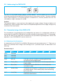
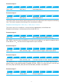
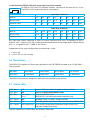
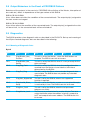
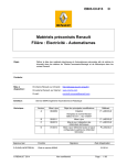
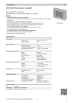
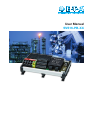
User Manual SVS16-PB-XX Sicherheitshinweis Eine Nichtbeachtung der Montage- und Bedienungsanleitung kann zu erheblichen Schäden am Gerät und an der Anlage führen. E-T-A übernimmt gegenüber Kunden oder Dritten keine Haftung, Gewährleistung oder Garantie für Mängel oder Schäden, die durch fehlerhaften Einbau oder unsachgemäße Handhabung unter Nichtbeachtung der Montageund Bedienungsanleitung verursacht sind. Caution Please follow these instructions carefully. Failure to comply, or misuse of this equipment, could result in serious damage both to the equipment itself and to the installation. E-T-A is unable to accept responsibility for customer or third party liability, warranty claims or damage caused by incorrect installation or improper handling resulting form non-observance of these instructions. Montageanleitung für Stromverteiler SVS16-PB-XX Bestell-Nr. Y 310 567 02 Index: b Ausgabe 03/2014 E-T-A Elektrotechnische Apparate GmbH Alle Rechte vorbehalten Installation manual for power distribution system SVS16-PB-XX Ref. number Y 310 567 02 Index: b Issue 03/2014 E-T-A Elektrotechnische Apparate GmbH All rights reserved 2 Contents 1 2 3 4 General 1.1 General mounting guidelines PROFIBUS-DP bus system SVS16-PB-XX 3.1 Overview 3.1.1 Schematic diagram 3.2 Terminals 3.2.1 Supply voltage load module 3.2.2 Supply voltage bus module 3.2.3 Load outputs 3.2.4 F slots 3.2.5 PROFIBUS DP bus connection 3.3 Addressing the SVS16-PB 3.4 Parameterising the SVS16-PB 3.4.1 Meaning of the parameters 3.5 Configuration of SVS16-PB 3.6 Baud rates 3.7 Status LEDs 3.8 Output behaviour with PROFIBUS failures 3.9 Diagnostics 3.9.1 Meaning of diagnostic data Technical data 3 4 4 5 5 5 6 6 6 7 7 7 7 8 8 8 10 11 11 12 12 12 14 1General The power distribution system SVS16-PB-XX provides selective overcurrent protection, power distribution in load circuits as well as switching and resetting of outputs. For integral consistent communication of operating and error conditions as well as switching and resetting of individual circuits on the DC 24 V level, the system is fitted with a fully featured PROFIBUS-DP interface. The track-mountable system has 8 (SVS16-PB-08) or 16 (SVS16-PB-16) slots and accommodates electronic circuit breakers type ESX10-125 (with reset input and status output) and ESX10-115 (with control input and status output) or the solid state remote power controller E-1048-7xx (with control input and status output). 1.1 General Mounting Guidelines l The power distribution system must only be installed by qualified personnel. Only after proper installation must the device be supplied with electrical power. l It is only intended for connection to extra low voltage (DC 24 V). l Connection to higher and/or not reliably disconnected voltage can cause perilous conditions or damages. l The maximum total current of the power distribution system must not be exceeded. Cable cross section and current rating of the protective elements must be adjusted to the current rating of the connected load in each load path. l The technical data of the circuit breakers installed have to be observed. l Provisions have to be made in the system or machine to prevent inadvertent start-up of parts of the system (e.g. by installing a safety PLC) in compliance with the »Machinery Directive 98/37/EG and EN 60204-1, Safety of Machinery«. In the event of a failure (short circuit / overload) the load circuit will be disconnected by the circuit breaker. l After tripping of the circuit breaker and before reset, the trip cause (short circuit or overload) has to be remedied. l The national regulations (e.g. for Germany DIN VDE 0100) have to be observed with regard to installation and selection of input and output lines. l Caution Electrostatic discharge (ESD). Device must only be opened by the manufacturer. Waste management directive Packaging is capable of recycling and should be led to reuse. 4 2 PROFIBUS-DP BUS SYSTEM PROFIBUS-DP is a master-slave-system and can connect up to 126 users. One bus segment can operate max. 32 users. For more information on the bus system, planning, mounting and operation of a PROFIBUS system please see the official documents of the PROFIBUS user organisation (PNO). The link www.profibus.com/downloads/ leads you to the following documents: l PROFIBUS (technical guideline) l PROFIBUS (planning guideline) l PROFIBUS (mounting guideline) l PROFIBUS (start-up guideline) 3SVS16-PB-XX 3.1Overview Bus-Adr. x10 1 1 1 4 4 1 4 GERMANY GERMANY 6 6 7 5 7 Typ: 19 5 2 2 4 GERMANY Typ: 19 F2 1 4 GERMANY 6 F1 1 4 GERMANY 1+ 4 GERMANY 6 7 Typ: 19 5 7 Typ: 19 5 7 Typ: 19 5 7 5 7 Typ: 19 5 2 2 2 2 2 F5 F6 6 Typ: 19 F7 GERMANY Typ: SVS16-PB08C13P01 F8 16C23 P02 X1 X2 X3 X4 X5 X6 X7 X8 2+ 1- 2- PE 2+ 1- 2- PE Fehler X50 GERMANY 6 F4 Reset 4 GERMANY 6 F3 x1 1 6 DC 24 V/40 A X21 1+ 1 PROFIBUS-DP + + - - P E P E X1 X2 X3 X4 X5 X6 X7 X8 5 Made in Germany 1+ 2+ X31 DC 24 V 1- 2- Bus 3.1.1 Schematic diagram SVS16-PB-08-xxx A1 load pcb ETA.SVS16-PB-08 bus pcb PROFIBUS-DP Slave defect bus bus address x10 x1 Reset F1 F7 F8 communication Bus- F2 Line GND SC Line GND SC Line GND SC Line GND SC +SV bus pcb X50 X1 bus pcb communication X2 + bus pcb communication SO bus pcb communication X8 X7 + Load IN+/RE SO Load IN+/RE SO Load IN+/RE Load IN+/RE SO PROFIBUS connection 9-pole D-SUB bus pcb communication + + - bus pcb + bus pcb - X21 - PE 1+ 2+ 1- 2- - PE - PE X31 DC 24 V PE PE 1+ 2+ 1- 2- DC 24 V / max. 40 A 3.2Terminals 3.2.1 Supply Voltage Load Module Rated voltage DC 24 V (18 ... 32 V) Total current max. 40 A DC 24 V (+) = 1+ / 2+ (2-way) DC 24 V (-) = 1- / 2- (2-way) PE = PE, connected to DC 24 V (-) Terminals X21 with type SVS16-PB-XX-C13-XX: 5-pole print screwless terminals (1+/2+/1-/2-/PE) cable cross section max. 10 mm2 with type SVS16-PB-XX-C23-XX: 5-pole print screw terminals (1+/2+/1-/2-/PE) cable cross section max. 16 mm2 screw terminals: M4 6 3.2.2 Supply Voltage Bus Module Rated voltage DC 24 V (18 ... 32 V) Current consumption max. 250 mA Terminals X31 2-pole push-in-terminal (1+/2+) cable cross section max. 1,5 mm2 2-pole push-in-terminal (1-/1-) cable cross section max. 1,5 mm2 3.2.3 Load Outputs Rated voltage DC 24 V (18...32 V) Load current max. 8A per terminal block / slot (L+) protected load output (+) (L-) minus return load (-) (PE)PE Terminals X1…X8 (X16) with type SVS16-PB-XX-C13-XX: three-level print spring-loaded terminals cable cross section max. 1.5 mm2 with type SVS16-PB-XX-C23-XX: three-level print screw terminals cable cross section max. 1,5 mm2 screw terminals: M3 3.2.3 F Slots Slots for types ESX10-115, ESX10-125 and E-1048-7xx. SVS16-PB-08... F1...F8 = terminals X1...X8 SVS16-PB-16... F1...F16 = terminals X1...X16 3.2.5 PROFIBUS-DP Bus Connection The 9-pole D-Sub connector recommended in the EN 50170 should be used as bus connection. On the SVS16 the bus connection is designed as bushing. Terminal: X50 1 2 6 3 7 4 8 5 9 Pin assignment of 9-pole Sub-D connector Pin-number 1 2 3 4 5 6 7 8 9 Signal free free B-Line RTS BUS-GND BUS-5V free A-Line free 7 Definition data line B control signal for ground to BUS-5V Vcc load resistors (max. 100mA) data line A 3.3 Addressing the SVS16-PB x10 78 78 x1 9 01 23 23 9 01 456 bus address 456 Any user in a PROFIBUS network requires a unique address. The user address on the PROFIBUS will be adjusted directly on the SVS16-PB-XX by means of two rotary switches. The rotary switches have a value range of 0…9. The ones position is marked with x1, the tens position with x10. The valid address range is between 01 and 99. Caution! The imported address is only read once after applying the supply voltage. Change of address will therefore only come into effect after removal and repeated application of the supply voltage or by actuation of the reset button. 3.4 Parameterising of the SVS16-PB For convenience of parameterising and configuration by means of a configuration software a master data file called ETA_0C9E.gsd will be made available for download on the E-T-A homepage. This file will hold all vital and basic characteristics for parameterising/configuration and for the operation at any PROFIBUS-DP master control unit. 3.4.1 Meaning of the Parameters As requested by the EN 50170, the SVS16-PB processes the parameter bytes 1-7. There are no other user parameter data. Design and meaning of the 7 parameter bytes are described in the following: Parameter byte 1 Bit 7 Bit 6 Bit 5 Bit 0 reserved Bit 1 Bit 2 Bit 3 reserved reserved WD_On Bit 4 Freeze_Req Bit 5 Sync_Req Bit 6 Unlock_Req Bit 7 Lock_Req Bit 4 Bit 3 Bit 2 Bit 1 Bit 0 If this bit is set to 0, response monitoring (WatchDog) of the SVS16 will be deactivated. This bit signals to the SVS16 that it shall be operated in the Freeze_mode. This bit signals to the SVS16 that it shall be operated in the Sync_mode. The Master sets this bit to 1 to release access to the SVS16 for another Master. This bit takes priority over the following bit 7/ Lock_Req. The Master sets this bit to 1 to block access to the SVS16 for other Masters. 8 Parameter byte 2 Bit 7 Bit 6 Bit 0 - Bit 7 Bit 5 Bit 4 Bit 3 WD_Fact_1 Bit 2 Bit 1 Bit 0 Bit 1 Bit 0 Watchdog factor 1 Parameter byte 3 Bit 7 Bit 6 Bit 0 - Bit 7 Bit 5 Bit 4 Bit 3 WD_Fact_2 Bit 2 Watchdog factor 2 The values held in the two bytes above represent factors for adjustment of the response monitoring time. The time of response monitoring will be calculated as follows: Response monitoring time = WD_Fact_1 * WD_Fact_2 * 10 ms Thus times from 10 ms to 650 sec. can be realised, independently of the Baud rate. Response monitoring is switched on or off by the bit WD_On. Parameter byte 4 Bit 7 Bit 6 Bit 0 - Bit 7 Bit 5 Bit 4 Bit 3 Min_TSDR Bit 2 Bit 1 Bit 0 Min. response time of SVS16-PB in tBit Min_TSDR is the time which the SVS16 has at least to wait before it can send its responses back to the Master. 11 tBit are the minimum requirement as per standard. Parameter byte 5 Bit 7 Bit 6 Bit 0 - Bit 7 Bit 5 Bit 4 Bit 3 Bit 2 Bit 1 Bit 0 Ident_Number_High Ident number of higher valence byte (0x0C) Bit 5 Bit 3 Parameter byte 6 Bit 7 Bit 6 Bit 0 - Bit 7 Bit 4 Ident_Number_Low Bit 2 Bit 1 Bit 0 Low Ident number of lower valence byte (0x9E) The SVS16-PB only accepts parameterising telegrams where the transmitted Ident-Number is identical with its own Ident-Number. Exception: the Min_TSDR, it can also be set in case the two bits Lock_Req and Unlock_Req are zero and the Ident_Number is not identical. Parameter byte 7 Bit 7 Bit 0 - Bit 7 Bit 6 Bit 5 Bit 4 Bit 3 Group_Ident Bit 2 Group assignment 9 Bit 1 Bit 0 This byte allows group assignment for the function Global_Control. Each bit represents a group. 7 6 5 4 3 2 1 x 0 Parameter byte 7: Group assignment x unit is part of group 1 unit is part of group 2 ... x unit is part of group 8 Note: will only be adopted if Lock_Req bit is set. 3.5 Configuration of SVS16-PB The SVS16-PB uses the general identifier format for configuration. This way of configuring will be supported by all Masters. As the SVS16-PB-XX is designed as a modular slave, the GSD file describes both the power distribution system with 8 and with 16 slots. On type SVS16-PB-08 you can configure one output module and one input module each. The system with 16 slots (SVS16-PB-16) has max. two output modules and 2 input modules selectable. One module describes 8 slots each. The following assignments are valid: Output byte 1 (Control/Reset) Slot no. F1 F2 F3 F4 F5 F6 F7 F8 Binary value 2^0 2^1 2^2 2^3 2^4 2^5 2^6 2^7 Decimal value 1 2 4 8 16 32 64 128 Slot no. F9 F10 F15 F16 Output byte 2 (Control/Reset) F11 F12 F13 F14 Binary value 2^0 2^1 2^2 2^3 2^4 2^5 2^6 2^7 Decimal value 1 2 4 8 16 32 64 128 Each output byte controls 8 slots and the lowest-valence bit (LSB) of the output byte 1 is assigned to the slot F1. The highest-valence bit (MSB) of the output byte 1 is assigned to slot F8. Along the lines of output byte 1 the lowest-valence bit (LSB) of output byte 2 is assigned to slot F9 and the highest-valence bit (MSB) is assigned to slot F16. Depending on the population of the SVS16-PB the following specifications are valid: a) slot fitted with E-1048-7xx (with control input and status output) 1 ➝ 24V ON ➝ E-1048-7xx switch on 0 ➝ 24V OFF ➝ E-1048-7xx switch off b) slot fitted with ESX10-115 (with control input and status output) 1 ➝ 24V ON ➝ ESX10-115 switch on 0 ➝ 24V OFF ➝ ESX10-115 switch off 10 c) slot fitted with ESX10-125 (with reset input and status output) An ESX10-125 in the OFF condition requires a reset pulse for reset of min. 10 ms. min. 10 ms The ESX10-125 cannot explicitly be switched off. Input byte 1 (Status) Slot no. F1 F2 F3 F4 F5 F6 F7 F8 Binary value 2^0 2^1 2^2 2^3 2^4 2^5 2^6 2^7 Decimal value 1 2 4 8 16 32 64 128 Slot no. F9 F10 F11 F12 F13 F14 F15 F16 Binary value 2^0 2^1 2^2 2^3 2^4 2^5 2^6 2^7 Decimal value 1 2 4 8 16 32 64 128 Input byte 2 (Status) Any input byte allows importing of status or failure indication of 8 slots. Assignment of the in dividual slots is identical with the assignment described above of the output bytes (LSB of output byte 1 is assigned to slot F1, MSB to slot F8 etc.). Independent of the type configurations the following is valid: 1 ➝ unit is ON 0 ➝ unit is OFF or slot is empty 3.6 Baud Rates The SVS16-PB supports all Baud rates specified in the PROFIBUS standard up to 12,000 Kbit/s. These include: 9.6 Kbit/s 19.2 Kbit/s 45.45 Kbit/s 93.75 Kbit/s 187.5 Kbit/s 500 Kbit/s 1,500 Kbit/s 3,000 Kbit/s 6,000 Kbit/s 12,000 Kbit/s The SVS16 automatically recognises the Baud rate specified by the Master. 3.7 Status LEDs LED »Bus« OFF Slave is OFF-Line, and/or no supply voltage available LED »Bus« ON Slave is in DATA-EXCHANGE mode LED »Bus« flash mode (1Hz.) Slave is in CLEAR mode (SVS16-PB is just being parameterised/initialised) LED »Fehler« OFF No error, and/or no supply voltage available LED »Fehler« ON Error during initialisation of the slave (Hardware failure, SVS16-PB) LED »Fehler« flash mode (1Hz.) Error during configuration/parameterisation of the slave (Network configuration error) The LED conditions in normal duty are written in bold type. 11 3.8 Output Behaviour in the Event of PROFIBUS Failures Behaviour of the outputs in the event of a PROFIBUS failure (failure of the Master, interruption of bus cable etc.) differs in dependence of the type number of the SVS16: SVS16-PB-XX-XX-P01. A bus failure does not affect the condition of the connected loads. The output byte(s) assigned to the slots remain unchanged. SVS16-PB-XX-XX-P02. A bus failure affects the condition of the connected loads. The output byte(s) assigned to the slots will be set to 0, i.e. the connected loads will be switched off. 3.9Diagnostics The SVS16 provides slave diagnostic data as described in the EN 50170. Set-up and meaning of the 6 Byte standard diagnostic data are described in the following: 3.9.1 Meaning of Diagnostic Data Byte 0 Bit 7 Bit 6 Bit 0 Bit 2 Diag.Station_Non_ Existent Diag.Station_Not_ Ready Diag.Cfg_Fault Bit 3 Diag.Ext_Diag Bit 4 Diag.Not_Supported Bit 5 Diag.Invalid_Slave_ Resp. Bit 6 Diag.Prm_Fault Bit 7 Diag.Master_Lock Bit 1 Bit 5 Bit 4 Bit 3 Bit 2 Bit 1 Bit 0 This bit is set by the Master , when the SVS16 does not respond. The SVS16 sets this bit to zero. This bit is set by the SVS16, when it is not yet ready for the data exchange. This bit is set by the SVS16, when the configuration data received from the Master are not identical with those determined by the SVS16. This bit is set by the Slave, when extended diagnostic data are available. The SVS16 does not provide any extended diagnostic data. This bit is set by the SVS16, when a non-supported function is required. This bit is set by the Master, as soon as a non-plausible reply is received by a slave. The SVS16 sets this bit to zero. This bit is set by the SVS16, when the last parameter telegram was faulty. The slave was parameterised by another Master! This bit is set by the Master when the address in byte 3 is unequal to 0xFF and unequal to the own address. The SVS16 sets this bit to zero. 12 Byte 1 Bit 7 Bit 6 Bit 5 Bit 0 Diag.Prm_Req Bit 1 Diag.Stat_Diag Bit 2 - Bit 3 Diag.WD_On Bit 4 Diag.Freeze_Mode Bit 5 Diag.Sync_Mode Bit 6 Diag.Not_Present Bit 7 Diag.Deactivated Bit 4 Bit 3 Bit 2 Bit 1 Bit 0 If this bit is set by the SVS16, it has to be re-parameterised and re-configured. As long as this bit is set by the SVS16, the Master has to pick up diagnostic data. It sets the bit for instance when it cannot provide user data. This bit is set by the SVS16 firmly to 1. This bit is set by the SVS16, as soon as its WatchDog is activated. This bit is set by the SVS16, as soon as it has received the command FREEZE. This bit is set by the SVS16, as soon as it has received the command SYNC. This bit is set by the Master, when the slave is not part of the parameter set of the Master. The SVS16 sets this bit to zero. This bit is set by the Master, as soon as the SVS16 is marked as inactive in the Master parameter set. The SVS16 sets this bit to zero. Byte 2 Bit 7 Bit 6 Bit 5 Bit 0 Bit 1 Bit 2 Bit 3 Bit 4 Bit 5 Bit 6 Bit 7 reserved reserved reserved reserved reserved reserved reserved Diag.Ext_Diag_ Overflow Bit 4 Bit 3 Bit 2 Bit 1 Bit 0 This bit is set as soon as there is an overflow of diagnostic data. For instance the slave can set this bit when there are more diagnostic data than it can record in the transmission buffer. The Master will set this bit when the slave sends more diagnostic data than the Master can enter into its diagnostic buffer. 13 Byte 3 Bit 7 Bit 6 Bit 0 - Bit 7 Bit 5 Bit 4 Bit 3 Diag.Master_Add Bit 2 Bit 1 Bit 0 Master address This byte holds the address of the Master which has parameterised the SVS16. If the SVS16 has not been parameterised by a Master, the slave will record the value 0xFF into byte 3. The following 2 bytes hold the 16-bit ident-number of the DP slave. The ident number of the SVS16 is 0x0C9E. Byte 4 Bit 7 Bit 6 Bit 0 – Bit 7 Bit 5 Bit 4 Bit 3 Bit 2 Bit 1 Ident_Number_High Ident number High-Byte (0x0C) Bit 5 Bit 3 Bit 0 Byte 5 Bit 7 Bit 6 Bit 0 – Bit 7 Bit 4 Bit 2 Bit 1 Ident_Number_Low Ident number Low-Byte (0x9E) Bit 5 Bit 3 Bit 0 Byte 6 Bit 7 Bit 6 Bit 4 Bit 2 Bit 1 Bit 0 This byte holds the block length of a possibly available extended diagnosis (Ext_Diag_Data). The SVS16 does not provide any extended diagnostic data. 4 Technical Data Supply load module: DC 24 V, max. 40 A (screw terminals or screwless terminals) +24 V (2-way), 0 V (2-way) and PE (1-way) max. 10 mm² Supply bus module: DC 24 V, max. 250 mA (push-in-terminals) +24 V (2-way), 0 V (2-way) max. 1.5 mm² Number of slots SVS16-PB-08: 8 slots SVS16-PB-16: 16 slots Population of slots (optional) l Load outputs max. 8 A per slot per load output Load+, Load-, and PE, 1.5 mm² each Communication interface PROFIBUS-DP to EN 50170 and/or IEC 61158 LED status indication module supply, bus status with electronic circuit protectors type ESX10-115 / -125 l with SSRPC type E-1048-7xx 14 Notes 15 M_SVS16-PB_e_300713 E-T-A Elektrotechnische Apparate GmbH Industriestraße 2-8 . D-90518 Altdorf Germany Tel. 09187 10-0 . Fax 09187 10-397 E-Mail: [email protected] . www.e-t-a.de