1
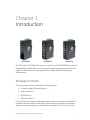
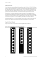
GE
Security
GE-DSG-8 DSGH-5 and 8
Ethernet Switch User Manual
P/N 1069175 • REV 1.0 • ISS 22FEB10
Copyright
© 2010 GE Security, Inc.
This document may not be copied in whole or in part or otherwise reproduced without prior
written consent from GE Security, Inc., except where specifically permitted under US and
international copyright law.
Disclaimer
The information in this document is subject to change without notice. GE Security, Inc.
(“GE Security”) assumes no responsibility for inaccuracies or omissions and specifically disclaims
any liabilities, losses, or risks, personal or otherwise, incurred as a consequence, directly or
indirectly, of the use or application of any of the contents of this document. For the latest
documentation, contact your local supplier or visit us online at www.gesecurity.com.
This publication may contain examples of screen captures and reports used in daily operations.
Examples may include fictitious names of individuals and companies. Any similarity to names
and addresses of actual businesses or persons is entirely coincidental.
Trademarks and patents
GE and the GE monogram are trademarks of General Electric Company.
Other trade names used in this document may be trademarks or registered trademarks of the
manufacturers or vendors of the respective products.
Intended use
Use this product only for the purpose it was designed for; refer to the data sheet and user
documentation for details. For the latest product information, contact your local supplier or visit
us online at www.gesecurity.com.
This product is intended to be supplied by a UL Listed Direct Plug-In Power Unit marked "Class 2"
or "LPS" and output rated 48 VDC, 380 mA minimum.
FCC compliance
This equipment has been tested and found to comply with the limits for a Class A digital device,
pursuant to part 15 of the FCC Rules. These limits are designed to provide reasonable protection
against harmful interference when the equipment is operated in a commercial environment.
This equipment generates, uses, and can radiate radio frequency energy and, if not installed
and used in accordance with the instruction manual, may cause harmful interference to radio
communications.
You are cautioned that any changes or modifications not expressly approved by the party
responsible for compliance could void the user's authority to operate the equipment.
N4131
Regulatory information
Manufacturer
GE Security, Inc.
HQ and regulatory responsibility:
GE Security, Inc., 8985 Town Center Parkway, Bradenton, FL 34202, USA
EU authorized manufacturing representative:
GE Security B.V., Kelvinstraat 7, 6003 DH Weert, The Netherlands
European Union directives
2002/96/EC (WEEE directive): Products marked with this symbol cannot be disposed of as
unsorted municipal waste in the European Union. For proper recycling, return this product to
your local supplier upon the purchase of equivalent new equipment, or dispose of it at
designated collection points. For more information see: www.recyclethis.info.
Contact information
For contact information see our Web site: www.gesecurity.com.
For contact information see our Web site: www.gesecurity.eu.
Content
Chapter 1 Introduction 1
Package Contents 1
How to use this Manual 2
Product Features 2
Chapter 2 Installation 5
Product Description 5
Wiring the Fault Alarm Contact 9
Chapter 3 Application 13
Installation Steps 14
Chapter 4 Switch Operation 15
Address Table 15
Learning 15
Forwarding & Filtering 15
Store-and-Forward 16
Auto-negotiation 16
Chapter 5 Troubleshooting 17
Appendix A Network Connection 19
Switch's RJ-45 Pin Assignments 19
RJ-45 Connector pin assignment 20
GE-DSG-8 DSGH-5 and 8 Ethernet Switch User Manual
i
ii
GE-DSG-8 DSGH-5 and 8 Ethernet Switch User Manual
Chapter 1
Introduction
GE-DSGH-5
GE-DSGH-8
GE-DSG-8
The GE Security GE-DSG/DSGH series is a 5 and 8-Port 10/100/1000Mbps Industrial
Gigabit Ethernet Switch with non-blocking wire-speed performance and new slim
type IP 30 metal shape for easy deployment in Heavy Industrial demanding
environments.
Package Contents
Check the contents of your package for following parts:
•
Industrial Gigabit Ethernet Switch x 1
•
User's Manual x 1
•
DIN Rail Kit x 1
•
Wall Mount Kit x 1
If any of these are missing or damaged, please contact your dealer immediately, if
possible, retain the carton including the original packing material, and use them
against to repack the product in case there is a need to return it to us for repair.
GE-DSG-8 DSGH-5 and 8 Ethernet Switch User Manual
1
Chapter 1: Introduction
How to use this Manual
This User Manual is structured as follows:
Section
Section Content
INTRODUCTION
Product description with features and specifications
INSTALLATION
Explains the features/functions of the Industrial Gigabit Ethernet Switch,
and how to physically install the Industrial Gigabit Ethernet Switch
APPLICATION
Explains the Industrial Gigabit Ethernet Switch application
SWITCH OPERATION
Explains the Industrial Gigabit Ethernet Switch transmit operation
TROUBLESHOOTING
Describes how to troubleshoot the Industrial Gigabit Ethernet Switch
APPENDIX A
Contains cable information for the Industrial Gigabit Ethernet Switch
Product Features
Physical Port
•
5-Port 10/100/1000Base-T RJ-45 with auto MDI/MDI-X function (GE-DSGH-5)
•
8-Port 10/100/1000Base-T RJ-45 with auto MDI/MDI-X function (GE-DSG-8 / GEDSGH-8)
Layer 2 Features
•
Complies with IEEE 802.3 10Base-T, IEEE 802.3u 100Base-TX, IEEE 802.3ab
1000Base-T Ethernet standard
•
Supports Auto-negotiation and 10/100Mbps half / full duplex and 1000Mbps full
duplex mode
•
High performance Store and Forward architecture, broadcast storm control,
runt/CRC filtering eliminates erroneous packets to optimize the network
bandwidth
•
Prevents packet loss with back pressure (Half-Duplex) and IEEE 802.3x PAUSE
frame flow control (Full-Duplex)
•
Integrated address look-up engine, support 8K absolute MAC addresses
•
9K Jumbo packet size support
•
Automatic address learning and address aging
2
GE-DSG-8 DSGH-5 and 8 Ethernet Switch User Manual
Chapter 1: Introduction
•
CSMA/CD Protocol
Industrial Case / Installation
•
IP-30 Metal case / Protection
•
DIN Rail and Wall Mount Design
•
12 to 48V DC, redundant power with polarity reverse protect function and
connective removable terminal block for master and slave power
•
-10 to 60 Degree C operating temperature on MC-4TX1FXMM-2km / MC4TX1FXSM-15KM / MC-4TX2FX
GE-DSG-8 DSGH-5 and 8 Ethernet Switch User Manual
3
Chapter 1: Introduction
Product Specifications
Model
GE-DSGH-5
GE-DSGH-8
GE-DSG-8
10/100/1000Base-T Ports
5
8
8
Installation
DIN rail kit and wall mount ear
Dimension (W x D x H)
5.31 x 3.42 x 1.26 inch / 135 x 87 x 32mm
Weight (lbs)
1.0 lbs
EFT
6KV
ESD
6KV
Hardware Specification
1.045 lbs
1.045 lbs
Electronic Specification
Power Input
12~48 VDC, Redundant power
Power Consumption
11.9 Watts / 40BTU
Power Connector
6-pin removable
screw terminal
13.2 Watts / 45BTU
13.2 Watts / 45BTU
Switch Specification
Switch Processing Scheme
Store-and-Forward
Address Table
8K entries
Buffer
176 kilobytes
Flow Control
Back pressure for half duplex,
IEEE 802.3x Pause Frame for full duplex
Switch fabric
10Gbps
16Gbps
16Gbps
Throughput
(Packet per second)
7.44Mpps@64bytes
11.9Mpps@64bytes
11.9Mpps@64bytes
Jumbo Frame
9Kbytes
Network cables
10/100/1000Base-T:
Cat. 3, 4, 5, 5e, 6 UTP cable (100meters, max.)
EIA/TIA-568 100-ohm STP (100meters, max.)
Environment Specification
Operating Temperature
-40°C ~75°C
Operating Humidity
5% ~ 95% (non-condensing)
-40°C ~75°C
Storage Temperature
-40°C ~85°C
Storage Humidity
5% ~ 95% (non-condensing)
-40°C ~85°C
-10°C ~60°C
-40°C ~85°C
Standards Conformance
4
Standards Compliance
IEEE 802.3 Ethernet
IEEE 802.3u Fast Ethernet
IEEE 802.3ab Gigabit Ethernet
IEEE 802.3x Full-duplex flow control
Stability testing
IEC60068-2-32 (Free fall),
IEC60068-2-27 (Shock),
IEC60068-2-6 (Vibration)
GE-DSG-8 DSGH-5 and 8 Ethernet Switch User Manual
Chapter 2
Installation
This section describes the features of the Industrial Gigabit Ethernet Switch's
components and guides you how to install it on the desktop. Basic knowledge of
networking is assumed. Please read this chapter completely before continuing.
Product Description
The GE Security GE-DSGH-5 and the GE-DSGH-8 are 5/8-Port 10/100/1000Mbps
Industrial Gigabit Ethernet Switches with non-blocking wire-speed performance with
a new slim type with IP 30 metal shape for easy deployment in Heavy Industrial
demanding environments.
With a 10/16Gbps internal switching fabric, the Industrial Gigabit Ethernet Switch can
handle extremely large amounts of data in a secure topology linking to a backbone
or high capacity servers.
The Industrial Gigabit Ethernet Switch has 8K MAC Address table and offers wirespeed packets transfer performance without risk of packet loss. The Gigabit ports
with 9K jumbo packet support can handle large amounts of data transmission in a
secure topology linking to a backbone or high-power servers. The high data
throughput of the device makes it ideal for most Gigabit environments.
All RJ-45 copper interfaces support 10/100/1000Mbps Auto-Negotiation for optimal
speed detection through RJ-45 Category 6, 5 or 5e cables. Support standard for AutoMDI/MDI-X that can detect the type of connection to any Ethernet device without
requiring special straight or crossover cables.
The Flow Control function allows Industrial Gigabit Ethernet Switch supported routers
and Servers to directly connect to this device for fast, reliable data transfer.
GE-DSG-8 DSGH-5 and 8 Ethernet Switch User Manual
5
Chapter 2: Installation
Product Overview
The GE Security Industrial Gigabit Ethernet Switch with 5/8 RJ-45 10/100/1000Mbps
ports for high-speed network connectivity. The Industrial Gigabit Ethernet Switch can
also automatically identify and determine the correct transmission speed and half /
full duplex mode of the attached devices with its 5/8 ports. The Gigabit port with 9K
jumbo frame feature supported, can handle extremely large amounts of data
transmission in a secure topology linking to a backbone or high-power servers.
The Industrial Gigabit Ethernet Switch also supports Store-and-Forward forwarding
scheme to ensure low latency and high data integrity, eliminates unnecessary traffic
and relieves congestion on critical network paths. With an intelligent address
recognition algorithm, the Industrial Gigabit Ethernet Switch can recognize up to 8K
different MAC address and enables filtering and forwarding at full wire speed.
Switch Front Panel
Figure 1 shows the front panels of Industrial Gigabit Ethernet Switch.
Figure 1: GE DSG-8 GE-DSGH-5 and GE-DSGH-8 front panels
6
GE-DSG-8 DSGH-5 and 8 Ethernet Switch User Manual
Chapter 2: Installation
Led Indicators
LED Indicators
LED
Color
Function
P1
Green
Lit: indicates the power 1 has power.
P2
Green
Lit: indicates the power 2 has power.
FAULT
Green
Lit: indicates the either power 1 or power 2 has no power.
1000
Green
Lit: indicates the Switch is successfully connecting to the network at 1000Mbps.
Off: indicates that the Switch is successfully connecting to the network at 10 or
1000Mbps.
Blink: indicates that the Switch is actively sending or receiving data over that port
100
Green
Lit: indicates the Switch is successfully connecting to the network at 100Mbps.
Off: indicates that the Switch is successfully connecting to the network at 10 or
100Mbps.
Switch Upper Panel
The upper panel of the Industrial Gigabit Ethernet Switch consists of one terminal
block connector within two DC power inputs. Figure 2 shows the upper panel of the
Industrial Gigabit Ethernet Switch.
Figure 2: Industrial Gigabit Ethernet Switch Upper Panel
Wiring the Power Inputs
The 6-contact terminal block connector on the top panel of Industrial Gigabit
Ethernet Switch is used for two DC redundant powers input. Please follow the steps
below to insert the power wire.
1. Insert positive / negative DC power wires into the contacts 1 and 2 for POWER
1, or 5 and 6 for POWER 2.
GE-DSG-8 DSGH-5 and 8 Ethernet Switch User Manual
7
Chapter 2: Installation
NOTE: This product is intended to be supplied by a UL Listed Direct Plug-In Power
Unit marked "Class 2" or "LPS" and output rated 48 VDC, 380 mA minimum.
Figure 3: Power Inputs
V1- V1 +
V2 - V2 +
2. Tighten the wire-clamp screws for preventing the wires from loosing.
Figure 3: Terminal Block
1
-
2
Power 1
+
3
4
Fault
5
6
Power 2
-
+
Note: The wire gauge for the terminal block should be in the range between 12 ~ 24
AWG.
8
GE-DSG-8 DSGH-5 and 8 Ethernet Switch User Manual
Chapter 2: Installation
Wiring the Fault Alarm Contact
The fault alarm contacts are in the middle of the terminal block connector as the
picture shows below. Inserting the wires, the Industrial Gigabit Ethernet Switch will
detect the fault status of a power failure, or port link failure (available for managed
model) and then forms an open circuit. The following illustration shows an application
example for wiring the fault alarm contacts.
Figure 4: Fault Alarm contacts
1
2
3
4
5
6
Insert the wires into the fault alarm contacts
Note: The wire gauge for the terminal block should be in the range between 12 ~ 24
AWG. Alarm relay circuit accepts up to 30V, max. 3A currents.
Figure 5: Alarm schematic
Industrial Switch
The cloesd circuit will poen when the
failure occurs.
Fault Alarm Contact 3 & 4
GE-DSG-8 DSGH-5 and 8 Ethernet Switch User Manual
9
Chapter 2: Installation
Mounting Installation
This section describes how to install the Industrial Gigabit Ethernet Switch and make
connections to it. Please read the following topics and perform the procedures in the
order being presented.
Note: In the installation steps below, this Manual use IGS-801 (GE Security 8 Port
Industrial Gigabit Switch) as an example. However, the steps for GE Security Industrial
Switch & Industrial Media Converter are similar.
Industrial DIN-Rail Mounting
The DIN-Rail is screwed on the Industrial Gigabit Ethernet Switch when in the factory.
If you need to replace the wall mount application with DIN-Rail application on
Industrial Gigabit Ethernet Switch, please refer to following figures to screw the DINRail on the Industrial Gigabit Ethernet Switch. To hang the Industrial Gigabit Ethernet
Switch, follow the below steps:
1. Screw the DIN-Rail on the Industrial Gigabit Ethernet Switch.
2. Lightly press the button of DIN-Rail into the track.
10
GE-DSG-8 DSGH-5 and 8 Ethernet Switch User Manual
Chapter 2: Installation
3. Check that the DIN-Rail is tightly secured on the track.
4. Please refer to following procedures to remove the Industrial Gigabit Ethernet
Switch from the track.
5. Lightly press the button of DIN-Rail for remove it from the track.
GE-DSG-8 DSGH-5 and 8 Ethernet Switch User Manual
11
Chapter 2: Installation
Wall Plate Mounting
To install the Industrial Gigabit Ethernet Switch on the wall, please follow the
instructions described below.
1. Remove the DIN-Rail from the Industrial Gigabit Ethernet Switch; loosen the
screws to remove the DIN-Rail.
2. Place the wall mount plate on the rear panel of the Industrial Gigabit Ethernet
Switch.
3. Use the screws to secure the wall mount plate on the Industrial Gigabit Ethernet
Switch.
4. Use the hook holes at the corners of the wall mount plate to hang the Industrial
Gigabit Ethernet Switch on the wall.
5. To remove the wall mount plate, reverse the steps above.
12
GE-DSG-8 DSGH-5 and 8 Ethernet Switch User Manual
Chapter 3
Application
In this section, we will describe how to install the Industrial Gigabit Ethernet Switch
into a typical application environment
.
GE-DSG-8 DSGH-5 and 8 Ethernet Switch User Manual
13
Chapter 3: Application
Installation Steps
1. Unpack the Industrial Gigabit Ethernet Switch.
2. Check the DIN-Rail is screwed on the Industrial Gigabit Ethernet Switch. (Please
refer to DIN-Rail Mounting section for DIN-Rail installation. If the DIN-Rail is not
screwed on the Industrial Gigabit Ethernet Switch.). If you want to wall mount the
Industrial Gigabit Ethernet Switch, then please refer to Wall Mount Plate Mounting
section for wall mount plate installation.
3. To hang the Industrial Gigabit Ethernet Switch on the DIN-Rail track or wall, please
refer to the Mounting Installation section.
4. Power on the Industrial Gigabit Ethernet Switch. (Please refer to the Wiring the
Power Inputs section for power input) The power LED on the Industrial Gigabit
Ethernet Switch will light up. Please refer to the LED Indicators section for
meaning of LED lights.
5. Prepare the twisted-pair, straight through Category 5 cable for Ethernet
connection.
6. Insert one side of Category 5 cables into the Industrial Gigabit Ethernet Switch
Ethernet port (RJ-45 port) and another side of category 5 cables to the network
devices' Ethernet port (RJ-45 port), ex: Switch, PC or Server. The UTP port (RJ-45)
LED on the Industrial Gigabit Ethernet Switch will light up when the cable
connected with the network device. Please refer to the LED Indicators section for
LED light meaning.
Note: Be sure the connected network devices support MDI/MDI-X. If it does not
support then use the crossover category 5 Cable.
7. When all connections are all set and LED lights all show normal, the installation is
complete.
14
GE-DSG-8 DSGH-5 and 8 Ethernet Switch User Manual
Chapter 4
Switch Operation
Address Table
The Industrial Gigabit Ethernet Switch is implemented with an address table. This
address table is composed of many entries. Each entry is used to store the address
information of some node in network, including MAC address, port no., etc. This
information is automatically obtained by the Industrial Gigabit Ethernet Switch.
Learning
When one packet comes in from any port. The Industrial Gigabit Ethernet Switch will
record the source address,and port number, and the other related information in
address table. This information will be used to decide either forwarding or filtering for
future packets.
Forwarding & Filtering
When one packet comes from some port of the Industrial Gigabit Ethernet Switch, it
will also check the destination address besides the source address learning. The
Industrial Gigabit Ethernet Switch will lookup the address-table for the destination
address. If not found, this packet will be forwarded to all the other ports except the
port which this packet comes in. And these ports will transmit this packet to the
network it connected. If found, and the destination address is located at different port
from this packet comes in, the Industrial Gigabit Ethernet Switch will forward this
packet to the port where this destination address is located according to the
GE-DSG-8 DSGH-5 and 8 Ethernet Switch User Manual
15
Chapter 4: Switch Operation
information from the address table. But, if the destination address is located at the
same port with this packet comes in, then this packet will be filtered. Thereby
increasing the network throughput and availability.
Store-and-Forward
Store-and-Forward is one type of packet-forwarding techniques. A Store-andForward Industrial Switch stores the incoming frame in an internal buffer, do the
complete error checking before transmission. Therefore, no error packets
occurrence, it is the best choice when a network needs efficiency and stability.
The Industrial Gigabit Ethernet Switch scans the destination address from the
packet-header, searches the routing table provided for the incoming port and
forwards the packet, only if required. The fast forwarding makes the switch attractive
for connecting servers directly to the network, thereby increasing throughput and
availability. However, the switch is most commonly used to segment existing hubs,
which nearly always improves overall performance. An Ethernet Switching can be
easily configured in any Ethernet network environment to significantly boost
bandwidth using conventional cabling and adapters.
Due to the learning function of the Industrial Gigabit Ethernet Switch, the source
address and corresponding port number of each incoming and outgoing packet are
stored in a routing table. This information is subsequently used to filter packets
whose destination address is on the same segment as the source address. This
confines network traffic to its respective domain, reducing the overall load on the
network.
The Industrial Gigabit Ethernet Switch performs "Store-and-Forward" therefore, no
error packets occur. More reliably, it reduces the re-transmission rate. No packet
loss will occur.
Auto-negotiation
The STP ports on the Industrial Gigabit Ethernet Switch have built-in "Autonegotiation". This technology automatically sets the best possible bandwidth when a
connection is established with another network device (usually at Power On or Reset).
This is done by detect the modes and speeds at the second of both device is
connected and capable of, both 10Base-T and 100Base-TX devices can connect with
the port in either Half- or Full-Duplex mode.
16
GE-DSG-8 DSGH-5 and 8 Ethernet Switch User Manual
Chapter 5
Troubleshooting
This chapter contains information to help you solve common issues. If the Industrial
Gigabit Ethernet Switch is not functioning properly, make sure the Industrial Gigabit
Ethernet Switch was set up according to instructions in this manual.
The per port LED is not lit
Solution:
Check the cable connection of the Industrial Gigabit Ethernet Switch.
Performance is bad
Solution:
Check the speed duplex mode of the partner device. The Industrial Gigabit Ethernet
Switch is run at Auto-negotiation mode and if the partner is set to half duplex, then
the performance will be poor.
Per port LED is lit, but the traffic is irregular
Solution:
Check that the attached device is not set to dedicate full duplex. Some devices use a
physical or software switch to change duplex modes. Auto-negotiation may not
recognize this type of full-duplex setting.
Why the Industrial Gigabit Ethernet Switch doesn't connect to the network
Solution:
Check per port LED on the Industrial Gigabit Ethernet Switch. Try another port on the
Industrial Gigabit Ethernet Switch Make sure the cable is installed properly Make sure
the cable is the right type Turn off the power. After a minnute, turn on the power
again.
GE-DSG-8 DSGH-5 and 8 Ethernet Switch User Manual
17
Chapter 5: Troubleshooting
Why the Industrial Gigabit Ethernet Switch doesn't connect to the network
Solution:
Check per port LED on the Industrial Gigabit Ethernet Switch. Try another port on the
Industrial Gigabit Ethernet Switch Make sure the cable is installed properly Make sure
the cable is the right type. Turn off the power. After a while, turn on power again
18
GE-DSG-8 DSGH-5 and 8 Ethernet Switch User Manual
Appendix A
Network Connection
Switch's RJ-45 Pin Assignments
1000Mbps, 1000Base-T
Contact
MDI
MDI-X
1
BI_DA+
BI_DB+
2
BI_DA-
BI_DB-
3
BI_DB+
BI_DA+
4
BI_DC+
BI_DD+
5
BI_DC-
BI_DD-
6
BI_DB-
BI_DA-
7
BI_DD+
BI_DC+
8
BI_DD-
BI_DC-
GE-DSG-8 DSGH-5 and 8 Ethernet Switch User Manual
19
Appendix A: Network Connection
10/100Mbps, 10/100Base-TX
RJ-45 Connector pin assignment
MDI
MDI-X
Contact
Media Dependant
Interface
Media Dependant
Interface -Cross
1
Tx + (transmit)
Rx + (receive)
2
Tx - (transmit)
Rx - (receive)
3
Rx + (receive)
Tx + (transmit)
4, 5
6
7, 8
Not used
Rx - (receive)
Tx - (transmit)
Not used
RJ-45 Connector pin assignment
12345
678
87654
321
The standard RJ-45 receptacle/connector
There are 8 wires on a standard UTP/STP cable and each wire is color-coded. The
following shows the pin allocation and color of straight cable and crossover cable
connection:
20
GE-DSG-8 DSGH-5 and 8 Ethernet Switch User Manual
Appendix A: Network Connection
Straight Cable
SIDE 1
SIDE 2
SIDE 1
SIDE 2
1 2 3 4 5 6 7 8 SIDE 1
1 2 3 4 5 6 7 8 SIDE 2
Cross Over Cable
1 2 3 4 5 6 7 8 SIDE 1
1 2 3 4 5 6 7 8 SIDE 2
Please make sure your connected cables are with same pin assignment and color as
above picture before deploying the cables into your network.
GE-DSG-8 DSGH-5 and 8 Ethernet Switch User Manual
21