1
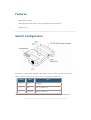
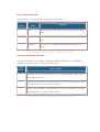
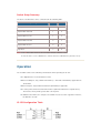
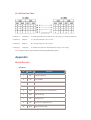
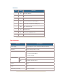
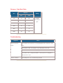
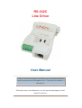
RS-232C
Line Driver
User Manual
Read this manual thoroughly and follow the installation procedures
carefully to prevent any damage to the IC-150 and/or the devices it
connects to.
All brand names and trademarks are the registered property of their
respective owners.
Packing Checklist
1 x IC-150 Line Driver
1 x User's Manual
If anything is damaged or missing, contact your dealer.
NOTE: This equipment has been tested and found to comply with the limits for a Class A
digital device pursuant to Part 15 of the FCC Rules. These limits are designed to provide
reasonable protection against harmful interference when the equipment is operated in a
commercial environment. This equipment generates, uses, and can radiate radio frequency
energy and, if not installed and used in accordance with the instruction manual, may cause
harmful interference to radio communications. Operation of this equipment in a residential
area is likely to cause harmful interference, in which case the user will be required to correct
the interference at his own expense.
Overview
The non powered IC-150 Line Driver facilitates efficient transmission and reception of serial data
without requiring an external power source. The unit drives your data at various speeds up to
19,200 bps over distances up to 0.5 miles using 24-gauage wire (transmitting at 110 bps over
distances up to 6.3 miles). Note that the slower the speed, the greater the distance, and
transmission performance may vary depending on operating conditions and wire gauge.
The IC-150 provides 1,500VAC lighting surge protection and excellent noise rejection through the
use of differential circuitry. The unit is switch-selectable for DCE/DTE. It provides asynchronous
transmission and operates full-duplex over four wires.
This compact unit plugs directly into the back of your asynchronous terminal, which saves the
space that a standalone unit would use, and also eliminates the bulk and cost of a separate
RS-232 interface (which requires a +12V DC source). Therefore, the IC-150 does not need a
separate outlet or power supply.
Features
DCE / DTE selectable
External Power Not Required - Power supplied by the RS-232 interface
Compact size
Switch Configuration
The IC-150 is configured by setting two slide switches. SW1 is used to select the Device Mode;
SW2 is used to select the Transmission Mode, as shown in the table below:
Position
SW1
SW2
1
DCE
Full Duplex
2
DTE
DCE, Tx or DTE, Rx
3
Loop Back
DCE, Rx, or DTE, Tx
Note: DCE means Date Communication Equipment; DTE means Date Terminal Equipment.
Device Mode Selection
The Device Mode is selected with SW1, as shown in the table, below:
SW1
Operating
Position
Mode
1
DCE
Meaning
The IC-150 is set to DCE mode and must be connected to a DTE
device.
2
DTE
The IC-150 is set to DTE mode and must be connected to a DCE
device.
3
Loop Back
The IC-150 is set to Monitor mode and monitors the phone line
signals.
Transmission Mode Selection
The Transmission Mode is selected with a combination of SW1 and SW2. Choices are Full Duplex,
or Simplex (Tx Only or Rx Only), as shown in the table, below:
SW2
Operating Mode
Position
1
Full Duplex. The IC-150 transmits and receives simultaneously. With this mode, it doesn't
matter what SW1 is set to.
2
DCE Tx / DTE Rx: if SW1 is set to DCE (SW1 pos. 1), the IC-150 only transmits; if SW1 is
set to DTE (SW1 pos. 2), the IC-150 only receives.
3
DCE Rx / DTE Tx: if SW1 is set to DCE (SW1 pos. 1), the IC-150 only receives; if SW1 is
set to DTE (SW1 pos. 2), the IC-150 only transmits.
Switch Setup Summary
The above considerations can be summarized in the following table:
IC-150 Operating Mode
SW1
SW2
Full Duplex
X
1
Simplex DCE Transmit
1
2
Simplex DCE Receive
1
3
Simplex DTE Transmit
2
3
Simplex DTE Receive
2
2
Loop Back
3
X
Note: 1. An X in the table means it doesn't matter what the switch is set to.
2. If the IC-150 is set as a DCE device, it must connect to a DTE device (and vice versa).
Operation
You should be aware of the following considerations when operating the IC-150:
The digital interface is RS-232C/CCITT V.24.
When in Full Duplex, only software handshake (i.e. Xon/Xoff or ETX/ACK) is applicable via
TD and RD.
When in Simplex, only hardware handshake (DTR/DSR) is applicable.
The unit is powered from host RS-232C interface (MC1488, SN75188 or equivalent ICs).
The interface must provide greater than +9V of power.
In addition to the TD line, the computer or terminal must at least also support the RTS line;
the DTR line; or both.
IC-150 Configuration Table
IC-150 Function Table
Function (1)
Full Duplex:
A and B may both transmit and receive. They only use software handshake
Function (2:
Simplex:
A is the transmitter; B is the receiver.
Function (3)
Simplex:
B is the transmitter; A is the receiver.
Function (4)
Loop Back:
A monitors the phone line data transmission (for self-test only).
Note: In Simplex Mode, only hardware handshaking (DTR/DSR) applies.
Appendix
RS-232 Pin Outs
DTE Mode:
Pin
Name
Function
1
PG
Protective Ground
2
TD
Transmit Data
3
RD
Receive Data
4
RTS
Request to Send (connected with pin 5)
5
CTS
Clear to Send (connected with pin 4)
6
DSR
Data Set Ready
7
SG
Signal Ground
8
CD
Receive Line Signal Detector
20
DTR
Data Terminal Ready
DCE Mode:
Pin
Name
Function
1
PG
Protective Ground
2
RD
Receive Data
3
TD
Transmit Data
4
CTS
Clear to Send (connected with pin 4)
5
RTS
Request to Send (connected with pin 5)
6
DTR
Data Terminal Ready
7
SG
Signal Ground
8
CD
Receive Line Signal Detector
20
DSR
Data Set Ready
Specifications
Function
Specification
Power Supply
No external power. Power derived from RS-232 interface.
Data Rate
Up to 19,200 bps under 0.5 miles.
Connectors
•
1 x DB-25 female
•
1 x 4 Post Terminal Block
•
1 x RJ-11 Socket
Function Switches
SW1
DCE / DTE / Loop Back Select
SW2
Full Duplex / Simplex Select
Housing
Plastic
Weight
60 g
Dimensions (L x W x H)
54 x 74.5 x 18.5 mm
Distance / Data Rate Table
Distance
bps
Wiring
kms
miles
110
10
6.3
1200
7
4.4
2400
5
3.1
4800
3.5
2.2
9600
2
1.3
19200
0.8
0.5
24 AWG
two twisted
pairs.
Troubleshooting
Symptom
Action
Data Transmission
Check that the IC-150 units are securely plugged into the computers' serial
Failure
ports.
Check that the cables are properly set up and properly connected.
Check that SW1 and SW2 are set properly.
Check that a device configured as DCE is connected to one configured as
DTE (and vice versa).
Data Loss or Error
Check that pins 4, 5, 6, 8, and 20 carry ± 9V DC.