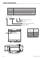
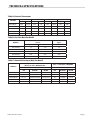
1
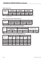
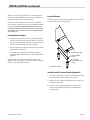
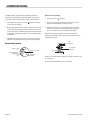
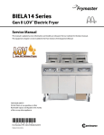
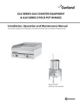
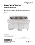
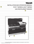
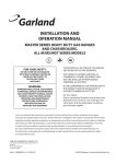
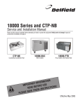
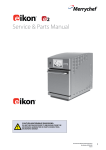
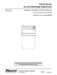
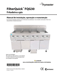
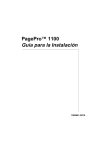
G24 SERIES
GAS-OPERATED
COUNTER GRIDDLE
Installation, Operation and Service Manual
This manual is updated as new information and models are released. Visit our website for the latest manual.
Model G24-24GFSD
Part # 4521357 (12/07)
IMPORTANT INFORMATION
WARNING:
This product contains chemicals known to the state of california to cause cancer and/or birth defects
or other reproductive harm. Installation and servicing of this product could expose you to airborne
particles of glass wool/ceramic fibers. Inhalation of airborne particles of glass wool/ceramic fibers
is known to the state of california to cause cancer. Operation of this product could expose you to
carbon monoxide if not adjusted properly. Inhalation of carbon monoxide is known to the state of
california to cause birth defects or other reproductive harm.
Keep appliance area free and clear of combustibles.
FOR YOUR SAFETY:
DO NOT STORE OR USE GASOLINE
OR OTHER FLAMMABLE VAPORS OR
LIQUIDS IN THE VICINITY OF
THIS OR ANY OTHER
APPLIANCE
WARNING:
IMPROPER INSTALLATION, ADJUSTMENT,
ALTERATION, SERVICE OR MAINTENANCE
CAN CAUSE PROPERTY DAMAGE, INJURY,
OR DEATH. READ THE INSTALLATION,
OPERATING AND MAINTENANCE
INSTRUCTIONS THOROUGHLY
BEFORE INSTALLING OR
SERVICING THIS EQUIPMENT
PLEASE READ ALL SECTIONS OF THIS MANUAL
AND RETAIN FOR FUTURE REFERENCE.
THIS PRODUCT HAS BEEN CERTIFIED AS
COMMERCIAL COOKING EQUIPMENT AND
MUST BE INSTALLED BY PROFESSIONAL
PERSONNEL AS SPECIFIED.
For Your Safety:
Post in a prominent location, instructions to be
followed in the event the user smells gas. This
information shall be obtained by consulting
your local gas supplier.
Users are cautioned that maintenance and repairs must be performed by a Garland authorized service agent
using genuine Garland replacement parts. Garland will have no obligation with respect to any product that has been
improperly installed, adjusted, operated or not maintained in accordance with national and local codes or installation
instructions provided with the product, or any product that has its serial number defaced, obliterated or removed,
or which has been modified or repaired using unauthorized parts or by unauthorized service agents.
For a list of authorized service agents, please refer to the Garland web site at http://www.garland-group.com.
The information contained herein, (including design and parts specifications), may be superseded and is subject
to change without notice.
Page 2
Part # 4521357 (12/07)
TABLE OF CONTENTS
Important Information . . . . . . . . . . . . . . . . . 2
Commissioning . . . . . . . . . . . . . . . . . . . . . . . 10
Model Designation. . . . . . . . . . . . . . . . . . . . . 4
Burner Adjustments . . . . . . . . . . . . . . . . . . . . . . . . . 10
Technical Specifications . . . . . . . . . . . . . . . . 5
Table A: Exterior Dimensions . . . . . . . . . . . . . . . . . 5
Table B: Gas Flow Rate Per Model . . . . . . . . . . . . . 5
Table C: Nominal Heat Input (Net) Per Model . . 5
Operation Instructions . . . . . . . . . . . . . . . . 11
Operating Controls. . . . . . . . . . . . . . . . . . . . . . . . . . 11
Lighting The Griddle . . . . . . . . . . . . . . . . . . . . . . . . 11
Safety . . . . . . . . . . . . . . . . . . . . . . . . . . . . . . . . . . . . . . 11
Table D: Injector Size . . . . . . . . . . . . . . . . . . . . . . . . . 6
Routine Maintenance & Cleaning . . . . . . 12
Table E: Setting Pressure For “Min”
Tap Position . . . . . . . . . . . . . . . . . . . . . . . . . . . . . . . . . 6
General Cleaning . . . . . . . . . . . . . . . . . . . . . . . . . . . 12
Table F: Aeration Shutter Setting /
Pilot Flame Length . . . . . . . . . . . . . . . . . . . . . . . . . . 6
Stainless Steel . . . . . . . . . . . . . . . . . . . . . . . . . . . 12
Table G: Australia Only – Injector Size,
NGC And Pressure . . . . . . . . . . . . . . . . . . . . . . . . . . . 6
Introduction . . . . . . . . . . . . . . . . . . . . . . . . . . . 7
Uncrating. . . . . . . . . . . . . . . . . . . . . . . . . . . . . . . . . . . . 7
Product Application . . . . . . . . . . . . . . . . . . . . . . . . . . 7
Optional Extras . . . . . . . . . . . . . . . . . . . . . . . . . . . . . . 7
Rating Plate. . . . . . . . . . . . . . . . . . . . . . . . . . . . . . . . . . 7
Installation . . . . . . . . . . . . . . . . . . . . . . . . . . . . 8
Statutory Regulations . . . . . . . . . . . . . . . . . . . . . . . . 8
Australia Specific Clause . . . . . . . . . . . . . . . . . . . . . . 8
Siting . . . . . . . . . . . . . . . . . . . . . . . . . . . . . . . . . . . . . . . . 8
Clearances . . . . . . . . . . . . . . . . . . . . . . . . . . . . . . . . . . . 8
Ventilation Air . . . . . . . . . . . . . . . . . . . . . . . . . . . . . . . 8
Painted Finishes . . . . . . . . . . . . . . . . . . . . . . . . . 12
Griddle Seasoning . . . . . . . . . . . . . . . . . . . . . . . . . . 12
Griddle Cleaning . . . . . . . . . . . . . . . . . . . . . . . . . . . . 12
Maintenance & Servicing Instructions . . 13
Gas Taps . . . . . . . . . . . . . . . . . . . . . . . . . . . . . . . . . . . . 13
Main Burners - Cleaning . . . . . . . . . . . . . . . . . . . . . 13
Pilot Burners - Cleaning . . . . . . . . . . . . . . . . . . . . . 13
Miscellaneous . . . . . . . . . . . . . . . . . . . . . . . . . . . . . . 13
Replacement Of Parts . . . . . . . . . . . . . . . . . 13
Gas Taps . . . . . . . . . . . . . . . . . . . . . . . . . . . . . . . . . . . . 13
Pilot Burner/Thermocouple/Spark Electrode . 14
Piezo Ignitor . . . . . . . . . . . . . . . . . . . . . . . . . . . . . . . . 14
Conversion Instructions . . . . . . . . . . . . . . . 14
Fault Finding . . . . . . . . . . . . . . . . . . . . . . . . . 15
Gas Connection . . . . . . . . . . . . . . . . . . . . . . . . . . . . . . 8
Gas Supply . . . . . . . . . . . . . . . . . . . . . . . . . . . . . . . . . . 8
Safety Concerns . . . . . . . . . . . . . . . . . . . . . . 15
Installation Procedure . . . . . . . . . . . . . . . . . . . . . . . . 9
Leg Installation . . . . . . . . . . . . . . . . . . . . . . . . . . . . . . 9
Installation Of Counter Stands (Optional) . . . . . . 9
Part # 4521357 (12/07)
Page 3
MODEL DESIGNATION
MODEL
DESCRIPTION
G24-24GFSD
610 mm wide x 324 mm high, heavy duty counter top griddle.
G24-36GFSD
914 mm wide x 324 mm high, heavy duty counter top griddle.
G24-48GFSD
1219 mm wide x 324 mm high, heavy duty counter top griddle.
G24-60GFSD
1524 mm wide x 324 mm high, heavy duty counter top griddle.
G24-72GFSD
1829 mm wide x 324 mm high, heavy duty counter top griddle.
SUFFIX DEFINITIONS:
G24
24, 36, 48, 60, 72
G
FSD
FLAME SAFETY DEVICES FITTED
GAS GRIDDLE
NOMINAL WIDTH OF GRIDDLE IN INCHES
BASE MODEL NUMBER
WIDTH
3/4" NPT INLET
(G24-24,G24-36)
1" NPT GAS INLET
(G24-48,G24-60,G24-72)
6-3/4"
(171mm)
*HEIGHT OF GRIDDLE PLATE
Model
Width
G24-24GFSD
G24-36GFSD
G24-48GFSD
G24-60GFSD
G24-72GFSD
24” (610mm)
36” (914mm)
48” (1219mm)
60” (1524mm)
72” (1829mm)
1-1/2"
(38 mm)
13-7/8"
(352 mm)
12-7/8" 10-1/4" *
(327mm) (259mm)
4" (102mm)
30-3/8"
(772mm)
1-1/2"
(38mm)
3/4" NPT INLET (G24-24,G24-36)
1" NPT GAS INLET (G24-48,G24-60,G24-72)
Page 4
Part # 4521357 (12/07)
TECHNICAL SPECIFICATIONS
Table A: Exterior Dimensions
MODELS
HEIGHT
WIDTH
DEPTH
WEIGHT
mm
Ins
mm
Ins
mm
Ins
Kg
Lb.
G24-24GFSD
324
12.75
610
24
781
30.75
109
240
G24-36GFSD
324
12.75
914
36
781
30.75
159
350
G24-48GFSD
324
12.75
1219
48
781
30.75
227
500
G24-60GFSD
324
12.75
1524
60
781
30.75
272
600
G24-72GFSD
324
12.75
1829
72
781
30.75
318
700
Table B: Gas Flow Rate Per Model
NATURAL GAS
( m3/h )
MODELS
PROPANE GAS
(kg/h )
G20 @ 20mbar
G25 @ 25 mbar
G31 @ 37/50 mbar
G24-24GFSD
1.9
1.97
1.4
G24-36GFSD
2.86
2.96
2.09
G24-48GFSD
3.81
3.94
2.8
G24-60GFSD
4.76
4.92
3.49
G24-72GFSD
5.71
5.91
4.19
Table C: Nominal Heat Input (Net) Per Model
MODELS
(G20 @ 20 mbar ) NATURAL GAS
( G25 @ 25 mbar ) NATURAL GAS
(G31 @ 37/50 mbar ) PROPANE
Nominal Heat Input (G20 / G25)
Nominal Heat Input
kW
BTU/HR
MJ/HR
kW
BTU/HR
MJ/HR
G24-24GFSD
18 / 16
61,400/54,600
64.8/57.6
18
61,400
64.8
G24-36GFSD
27 / 24
92,150/81,900
97.2/86.4
27
92,150
97.2
G24-48GFSD
36 / 32
122,850/109,200
129.6/115.2
36
122,850
129.6
G24-60GFSD
45 / 40
153,500/136,500
161.9/144.0
45
153,500
161.9
G24-72GFSD
54 / 48
184,250/163,750
194.4/172.7
54
184,250
194.4
Part # 4521357 (12/07)
Page 5
TECHNICAL SPECIFICATIONS continued
Table D: Injector Size
MODEL/
SECTION
G20/G25 @ 20/25 mbar
(NATURAL)
G31 @ 37mbar
(PROPANE)
G31 @ 50 mbar
(PROPANE)
Injector Size
Injector Size
Injector Size
I.D. #
mm
I.D. #
mm
I.D. #
mm
43
2.3
53
1.5
54
1.4
All
NOTE:
The pressure must be measured at the pressure test nipple located on the main manifold pipe
with all burners lit.
Table E: Setting Pressure For “Min” Tap Position
MODELS
2ND Family, Group H
3RD Family, Group 3P
(G20 @ 20 mbar) NATURAL GAS
(G31 @ 37/50 mbar) PROPANE
ALL
mbar
“ W.C.
mbar
“ W.C.
1.25
0.5
2.49
1
Table F: Aeration Shutter Setting / Pilot Flame Length
MODELS
ALL
2ND Family, Groups H,L & E.
3RD Family, Group 3P
( G20/G25 @ 20/25 mbar)
NATURAL GAS
( G31 @ 37/50 mbar ) PROPANE
Pilot Flame Length
mm
Ins.
mm
Ins.
mm
Ins.
19
0.75
27
1.062
12.5
0.5
Table G: Australia Only – Injector Size, NGC And Pressure
NATURAL GAS
PROPANE GAS
MODELS
Inj. Dia
mm
MJ/H
Gas
Pressure
(kPa)
Inj. Dia.
mm
MJ/H
Gas
Pressure
(kPa)
G24-24GSFD
2.85
63.3
1.0
1.7
63.3
2.49
G24-36GFSD
2.85
95.0
1.0
1.7
95.0
2.49
G24-48GFSD
2.85
126.6
1.0
1.7
126.6
2.49
G24-60GFSD
2.85
158.3
1.0
1.7
158.3
2.49
G24-72GFSD
2.85
189.9
1.0
1.7
189.9
2.49
Page 6
Part # 4521357 (12/07)
INTRODUCTION
IMPORTANT: The following instructions should be read
carefully as the manufacturer cannot be held responsible
for any damage to property, persons or animals caused by
incorrect installation or operation of the appliance.
You have purchased the finest commercial cooking
equipment available. Like any other fine, precision built
piece of equipment it should be given regular care and
maintenance.
Your new equipment must be installed and adjusted by a
competent person in accordance with the law. Failure to
install appliances correctly could lead to prosecution. It is in
your own interests and that of safety to ensure that the law is
complied with.
Your Garland dealer is well qualified to provide this service.
Periodic inspections by your dealer or qualified service
company are recommended to check temperatures, burner
adjustments and to ensure that moving parts are operative.
Whenever possible avoid overheating idle equipment as this
is the primary cause for increased service cost.
Product Application
Griddle tops are designed to have food cooked directly on
the surface. Do not put pots or pans on the griddle surface.
This will scratch or nick the surface and result in improper
cooking or sticking of the product. Never salt food over a
griddle since this will build up gummy residue making it
difficult to clean.
Avoid hitting the surface of the griddle with the edge of a
spatula since this will cause nicks. The most frequently used
temperature are 149°C to 177°C (300°F to 350°F). After one
firing the griddle plate will discolor. This is normal and will
not affect the performance.
NOTE: Many parts of the griddle are made from raw steel,
i.e., the griddle plate and can react with moisture forming
surface rust. This is normal and is not considered a defect.
Clean with a stainless steel or fiber pad. A light coating of salt
free oil may be applied to prevent further rusting.
Optional Extras
“Regular maintenance ensures peak performance.”
•
Counter Stand.
Uncrating
•
Legs.
1. Check crate for possible damage sustained during transit.
Carefully remove unit from crate and again check for
damage. Any damage to the appliance must be reported
to the carrier immediately.
Rating Plate
2. The wires for retaining the burners & other packing
material must be removed from unit. Any protective
material covering stainless steel parts must also be
removed.
3. The type of gas and the supply pressure that the
equipment was set up for at the factory is noted on the
data plate and on the packaging. This type of gas supply
must be used.
4. Do not remove permanently affixed labels, warnings or
data plates from the appliance, for this may invalidate the
manufacturer’s warranty.
Part # 4521357 (12/07)
The rating plate is readily accessible, located behind the
grease drawer. It contains all of the pertinent information
required by the installer.
In the event you have any questions concerning the
installation use care or service of this or any other Garland
product, write or call our Product Service Department. When
corresponding with the factory or your equipment dealer
regarding service problems or replacement parts, be sure
to refer to the particular unit by the correct model number,
including prefix and suffix letter and numbers and serial
number. The rating plate affixed to the unit contains this
information.
For proper operation, the fuel information on the rating plate
of your new equipment must match you fuel supply.
Page 7
INSTALLATION
Statutory Regulations
Ventilation Air
The installation of this appliance must be carried out by
a competent person and in accordance with the relevant
regulations, standards, codes of practice and the related
publications of the Country of destination. Failure to install
appliances correctly can lead to prosecution. It is in your own
interests and that of safety to insure that there is compliance
with the law.
The area in which the appliance is installed must be
adequately ventilated to provide air for combustion, removal
of products of combustion, etc. The use of a mechanical
extract system should be considered.
Australia Specific Clause
This appliance must be installed in accordance with the
manufacturers instructions, local gas fitting regulations
and requirements of AS 5601 / AG 601 installation code.
All burner adjustments and settings should be made by a
qualified gas technician.
Siting
Note 1: The room containing the appliance is required to
have a permanent air vent. The minimum effective area of
the vent is related to the maximum rated heat input of the
appliance and shall be4.5 cm2 per kW in excess of 7 kW.
Note 2: Air vents should be of such a size to compensate for
the effects of any extract fan in the premises.
Gas Connection
The base on which the unit is to be sited must be firm,
smooth and capable of adequately supporting the weight of
the appliance and any ancillary equipment. ( Refer to table
A for weight specifications ). Once in position check that
the unit is level, both front to back and side to side. Adjust if
necessary using the leveling feet on the four corners of the
legs fitted. Any openings in the wall behind or beside the
appliance must be sealed.
Clearances
The space in which the appliance is to be sited must include
the minimum installation clearances to combustible surfaces.
Minimum Installation Clearances
To Adjacent Combustable Walls
- All Models
Sides
6” (152mm)
Back
6” (152mm)
Type Of Floor Or Base
Non Combustible or Combustible
with 2” (51mm) legs
Page 8
The following notes are intended to give general guidance.
For detailed recommendations, refer to the applicable
code(s) in the Country of destination.
The gas pipe connection is made at the left hand side of
the equipment. The size of the pipe work supplying the
appliance must not be less than the inlet connection which is
ISO 7/R 3/4”. After installation, the complete pipe work must
be checked for soundness.
Gas Supply
The local gas region should be consulted at the installation
planning stage in order to establish the availability of an
adequate supply of gas and to ensure that the meter is
adequate for the required flow rate. The pipe work from
the meter to the appliances must be of an appropriate size.
Where a number of appliances are installed in a battery, no
more than five should be served by any one supply pipe.
All fixed ( non mobile ) appliances MUST be fitted with a
manual gas cock upstream of the appliance to provide a
means of isolation for servicing or cleaning purposes. A
union or similar means of disconnection must be provided
between the gas cock and the appliance.
A manually operable valve must be fitted to the gas supply
to the kitchen to enable it to be isolated in an emergency.
Wherever practical, this shall be located either outside the
kitchen or near to an exit in a readily accessible position.
Part # 4521357 (12/07)
INSTALLATION continued
Where it is not practical to do this, an automatic isolation
valve system shall be fitted which can be operated from a
readily accessible position near to the exit.
Leg Installation
The leg channel is located on the package base. This channel
must be installed when using the legs.
At locations where the manual isolation valve is fitted or
the automatic system can be reset a notice MUST be fitted
stating: “ALL DOWNSTREAM BURNER AND PILOT VALVES
MUST BE TURNED OFF PRIOR TO ATTEMPTING TO RESTORE
THE SUPPLY. AFTER EXTENDED SHUT OFF, PURGE BEFORE
RESTORING GAS.”
Installation Procedure
1. Carefully remove unit from carton. All packing material
must be removed from the unit. On stainless steel units,
the protective material covering the stainless steel must
be removed immediately after unit is installed.
2. Place the appliance in the required position and level by
means of the leveling feet.
3. Connect the gas supply pipe work to the appliance.
The connection is made to the rear left hand side of the
appliance.
BOTTOM OF UNIT
A gas isolation cock must be fitted in the supply to the
appliance. The gas isolation cock must be sited in a position
which is easily accessible to the user.
4" [102mm]
ADJUSTABLE LEG
(QTY 4)
LEG CHANNEL
(QTY 2)
LEG INSTALLATION
Installation Of Counter Stands (Optional)
1. Assemble and level the counter stand as illustrated in the
instructions found in the counter stand carton.
2. Remove and discard the levelling bolts on the unit to be
installed on the stand.
3. Place the unit in the desired position on the counter
stand, securing with the fasteners provided with the
counter stand.
Part # 4521357 (12/07)
Page 9
COMMISSIONING
The whole of the gas installation, including the meter,
should be inspected, purged and tested for soundness in
accordance with the codes of the Country of destination.
Minimum Flame Setting
1. Ensure that all controls are in the “ ” position and turn
on the main gas supply.
2. Connect a U-gauage manometer to the pressure test
nipple located downstream of the gas tap.
2. Remove the grease drawer & upper & lower fascia panels
and connect a U-gauge manometer to the pressure test
point on the main manifold. Operate the main burners in
accordance with the instructions given in the Operation
Instructions.
3. With a screw driver, turn the adjuster on the tap body
clockwise to reduce or counter-clockwise to increase
pressure. Set pressure to correspond with Table E.
3. Check that the supply pressure is correct. If necessary,
adjust the supply pressure to give the required setting.
1. Set gas tap to low “ ” position.
When all the settings have been checked, remove the
U-gauge manometer, replace the pressure test point screw
and the front panels.
Pilot
Adjuster
Burner Adjustments
Low Flame
Adjuster
Fixing Screw
Injector Location
Required Length
of Opening
Aeration
Shutter
Test Point
Tell the user of the location of the gas isolation cock for use in
an emergency.
Leave this Manual with the user or purchaser.
Page 10
Part # 4521357 (12/07)
OPERATION INSTRUCTIONS
Operating Controls
Lighting The Griddle
NOTE: Ensure the gas supply to the appliance is turned “ON”.
During the initial ignition cycle, air must be purged from the
gas line and thus it may take one or two minutes for the pilot
burner to ignite.
1. Push in the tap and turn it counter-clockwise to the
ignition position “ ”.
OFF
2. Holding the tap fully in, light the pilot with a match or
taper.
3. When the pilot is lit, continue to hold the tap fully in for 20
seconds, then release it If the pilot goes out, wait for five
(5) minutes then repeat from step 1.
4. When the pilot is established, push the tap in and turn it
counter-clockwise to the full flame “ ” position.
IGNITION
5. For low flame or simmer, push the tap in and turn it
counter-clockwise to the low flame “ ” position.
6. To shut the burner off, turn the dial to the “ ” symbol and
the safety device will disengage within 60 seconds.
Safety
FULL FLAME
It is the responsibility of the supervisor or equivalent
person to ensure that users of this equipment wear suitable
protective clothing and to draw attention to the fact that
some parts will by necessity become very hot and will cause
burns if touched accidentally.
LOW FLAME
Part # 4521357 (12/07)
Page 11
ROUTINE MAINTENANCE & CLEANING
General Cleaning
Griddle Cleaning
Painted Finishes
To produce evenly cooked, browned griddle products, keep
the griddle free from carbonized grease. Carbonized grease
on the surface hinders the transfer of the heat from the
griddle surface to the food product. This results in uneven
browning and loss of cooking efficiency and worst of all,
carbonized grease tends to cling to grilled foods, giving hem
a highly unsatisfactory and unappetizing appearance. To
keep the griddle clean and operating at peak performance,
follow these simple instructions.
Establish a regular cleaning schedule. Any spills should be
wiped off immediately. The unit should be allowed the cool
down before cleaning any surfaces. Wipe exposed cleanable
surfaces when cool with a mild detergent and hot water.
Stubborn residue spots may be removed with a scouring
pad. Dry thoroughly with a clean cloth.
Stainless Steel
Stainless steel should be cleaned using a mild detergent,
a soft cloth and hot water. If it is necessary to use a nonmetallic scouring pad, always rub in the direction of the grain
in the metal to prevent scratching. Wash a small area at a
time and rinse the washed area with a clean sponge dipped
into a disinfectant and wipe dray with a soft cloth before it
can dry.
Use only stainless steel or, wood or plastic tools to scrape
off heavy deposits of grease or oil. Do not use ordinary
steel scrapers or knives as particles of iron may become
embedded are rust. NEVER USE STEEL WOOL.
Griddle Seasoning
Remove all factory applied protective material by washing
with hot water, mild detergent or soap solution.
Apply a thin coat of cooking oil to the griddle surface, about
one ounce per square foot of griddle surface. Spread over the
entire griddle surface with a cloth to create a thin film. Wipe
off any excess oil with a cloth.
Heat the griddle slowly for 15 to 20 minutes, then wipe away
the oil. Repeat the procedure 2 to 3 times until the griddle
has a slick mirror like finish. Do this until you have reached
the desired cooking temperature.
After each use: Clean griddle thoroughly with grill scraper
or spatula. Wipe off any excess debris left from the cooking
process.
Once a day: Clean griddle surface with a grill brick and grill
pad. Remove the grease container and clean thoroughly, in
the same manner as any ordinary cooking utensil.
Once a week: Clean the griddle surface thoroughly. If
necessary, use a grill stone or grill pad over the griddle
surface. Rub with the grain of the metal while still warm. A
detergent may be used on the surface to help clean it, but
care must be taken to be sure it is thoroughly removed.
After removing the detergent, the surface plate should be
covered with a thin film of oil to prevent rusting. To remove
discolorations use a non-abrasive cleaner. Before re-using,
the griddle must be reseasoned. Keep the griddle drain tube
to the grease container clean at all times.
CAUTION: This griddle plate is steel, but the surface is
relatively soft and can be scored or dented by the careless
use of a spatula. Be careful not to dent, scratch, or gouge the
plate surface as this will cause food to stick in those areas.
Note that since this is a steel griddle, if a light coating of oil
is not always present, rust will develop on the exposed and
uncoated areas.
IMPORTANT: Do not attain a high griddle temperature
(232°C/450°F) during the “break-in” period.
NOTE: Steel griddle surface will tone (blue discoloration)
from the heat. This toning will not diminish function or
operation and is not a defect.
Page 12
Part # 4521357 (12/07)
MAINTENANCE & SERVICING INSTRUCTIONS
To ensure efficient and safe operation of the appliance it is
recommended that servicing be carried out by a competent
person at regular intervals, the frequency of which will vary,
depending on the installation conditions and usage. Usually
once per year is adequate.
WARNING:
Turn off the gas supply to the appliance at the service cock
before commencing any servicing work.
IMPORTANT:
Test for gas soundness on completion of any servicing work.
Gas Taps
Pilot Burners - Cleaning
1. Remove the main burners. (Refer to the section titled
“Main Burners - Cleaning”).
2. Disconnect the pilot gas supply pipe from the pilot jet.
3. Remove the pilot jet.
4. Clean by blowing through or washing. Do not use a wire
to clear the pilot jet.
5. Reassemble in the reverse order.
Miscellaneous
1. Check for loose fasteners. Tighten as necessary.
Re-greasing of the taps is not recommended. If the tap
spindles become seized or difficult to turn, refer to the
Replacement of parts section in this manual.
Main Burners - Cleaning
1. Lift off the griddle plate. (Use caution. This will require
assistance due to the weight of the griddle).
2. Lift the rear of the burner and slide backwards off the
injector.
3. Clean the burners with a stiff scrubbing brush.
4. Shake well to remove any debris from the inside of the
burner.
5. Reassemble in the reverse order.
2. Wipe exposed cleanable surfaces with a mild detergent
and hot water. Stubborn residue may be removed with
a lightweight non-metallic scouring pad. Stainless steel
areas should be washed with a mild detergent, hot
water and a soft cloth. If necessary to use a non-metallic
scouring pad always rub in the direction of the grain in
the metal to prevent scratching. NEVER USE STEEL WOOL.
3 Check the operation of all thermocouples and flame
safety devices by lighting the pilots individually and
then blowing them out. Listen for the flame failure valve
clicking closed. This action must occur within 60 seconds
of extinguishing the pilot.
4. Clean out grease drawer and wash thoroughly in hot
soapy water. Dry thoroughly.
REPLACEMENT OF PARTS
WARNING:
Turn off the gas supply to the appliance at the service cock
before commencing any servicing work.
IMPORTANT:
Test for gas soundness on completion of any servicing work.
Gas Taps
1. Pull the control knob off each tap and remove the grease
drawer and the upper & lower fascia panels.
2. Disconnect the thermocouple connection at the rear of
the gas tap.
3. Disconnect the pilot and main burner tubing connections
at the gas tap.
Part # 4521357 (12/07)
Page 13
REPLACEMENT OF PARTS continued
4. Break the compression nut at the inlet of the gas tap and
replace the tap.
5. Remove the two (2) screws that secure the pilot
mounting bracket to aeration pan and remove the pilot
burner/thermocouple or electrode as appropriate.
5. Reassemble in the reverse order.
Pilot Burner/Thermocouple/Spark Electrode
6. Replace the faulty component and reassemble in the
reverse order.
1. Remove the main burner following the procedure given
under Maintenance & Servicing.
Piezo Ignitor
1. Pull the control knob off each gas tap on the unit.
2. Remove the grease drawer & upper & lower fascia panels
to access the multifunctional control.
2. Remove the lower fascia panel.
3. Disconnect the thermocouple connection at the rear of
the gas tap.
3. Remove the wire lead from the piezo ignitor & remove
the ignitor from the panel.
4. Disconnect the pilot tube connection/thermocouple
connection at the gas tap.
4. Replace with new ignitor & reassemble in the reverse
order.
CONVERSION INSTRUCTIONS
Servicing must be carried out by a competent person in
accordance with the law.
WARNING:
Turn off the gas supply to the appliance at the service cock
before commencing any servicing work.
IMPORTANT:
Test for gas soundness on completion of any servicing work.
1. Ensure that all of the parts necessary to make the
conversion have been supplied as follows:
a. Injector fittings ( One required for each main burner )
b. Pilot injector fittings ( One required per pilot burner )
c. Gas adjustment label ( One required per unit )
d. Data plate ( One required per unit )
If any of the required parts are missing, contact your Garland
dealer before attempting to carry out the conversion
NOTE: Conversion kits supplied for G31 gas will contain
redundant fittings and markings covering both 37 mbar & 50
mbar gas supplies.
Page 14
2. Remove the burners following the instructions given in
this manual.
3. Replace each injector fitting with the new fitting that is
supplied.
NOTE: Before doing so, refer to Table D (Table G for Australian
Models) in this manual to ensure that the correct injector has
been supplied for the gas supply being converted to.
4. Replace each pilot injector fitting with the new fitting
supplied.
NOTE: There are two sizes of pilot injectors identified as
follows
a. # 32 (2nd family gases) Natural Gas
b. # 23 (3rd family gases) Propane
Ensure that you have the correct pilot injector before
replacing.
Upon completion of all the above operations, follow the
section in the manual on “Commissioning” and ensure
that the setting pressure and all burner flame settings are
adjusted accordingly.
Part # 4521357 (12/07)
FAULT FINDING
PROBLEM
Burner flame too large.
Burner flame soft - yellow tip.
Delayed Ignition
Pilot burner will not ignite
Pilot Keeps Extinguishing.
Low millivolt output on open circuit
test.
POSSIBLE CAUSE
Incorrect setting pressure or injector.
SOLUTION
Check setting pressure and injector.
Insufficient primary air.
Check primary aeration for blockage.
Pilot burner flame too small.
Check pilot flame adjustment.
Burner ports blocked
Clean blocked burner ports.
Incorrect setting pressure.
Check setting pressure.
Pilot orifice blocked.
Clean pilot jet.
Pilot adjusting screw closed.
Open pilot adjuster.
Pilot flame too small.
Check pilot.
Loose thermocouple connection.
Tighten connection.
Faulty thermocouple.
Replace thermocouple.
Faulty flame safety device.
Replace flame safety device.
Pilot flame too small
Adjust pilot flame length.
Defective thermocouple.
Replace thermocouple.
Millivolt output high in open circuit test
Faulty flame safety device
but low in closed circuit test.
Replace flame safety tap
Millivolt output high on closed circuit
test but flame safety tap will not stay
open.
Replace flame safety tap.
Faulty flame safety device
SAFETY CONCERNS
It is essential that the instructions in the booklet be strictly
followed for the safe and economically operation of the
equipment. If it is known or suspected that a fault exists on
the appliance then it must not be used until the fault has
been rectified by a competent person.
Part # 4521357 (12/07)
Page 15
GARLAND
1177 KAMATO ROAD, MISSISSAUGA, ONTARIO, CANADA, L4W1X4
888-442-7526
WWW.GARLAND-GROUP.COM
Every new piece of Manitowoc Foodservice equipment comes with KitchenCare™ and you choose the level of service that meets
your operational needs from one restaurant to multiple locations.
StarCare – Warranty & lifetime service, certified OEM parts, global parts inventory, performance audited
ExtraCare — CareCode, 24/7 Support, online/mobile product information
LifeCare – Install & equipment orientation, planned maintenance, KitchenConnect™, MenuConnect
Talk with KitchenCare™ • 1-844-724-CARE • www.mtwkitchencare.com
To learn how Manitowoc Foodservice and its leading brands can equip you, visit our global web site at
www.manitowocfoodservice.com, then discover the regional or local resources available to you.
©2014 Manitowoc Foodservice except where explicitly stated otherwise. All rights reserved. Continuing product improvement may necessitate change of specifications without notice.