1
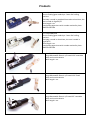
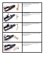
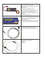
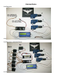
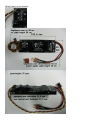
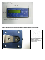
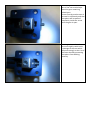
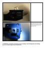
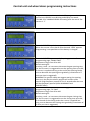
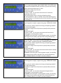
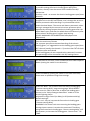
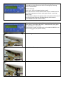
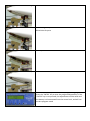
PROFESSIONAL LINE AND FLYING FOX ELECTRIC LANDING GEARS
USER MANUAL
READ ALL INSTRUCTIONS CAREFULLY PRIOR TO USE
IMPORTANT: DO NOT reverse the electric power polarity; the control unit is not
protected from reverse polarity; strictly respect the polarity: red + (positive), black –
(negative).
Reversing the electric power polarity will immediately damage the control unit; the specific
damage caused by electric power reversal is not covered by the warranty.
All of our products are tested before being issued.
Use only 2 cells, 7,4 volts dc li-po battery, at least/not less than 2200 mAh .
Do not immerse Flying Fox products in any type of liquid.
Do not put Flying Fox products in/near any type of fire.
Do not dispose of Flying Fox products in domestic waste. According to Directive 2002/95CE,
2002/96CE and 2003/108CE, devices marked with the cancelled waste bin symbol
must not be discarded in standard household waste. At the end of its life, the device must
be disposed in the manner recommended for electronic waste
Do not leave Flying Fox products in direct sunlight.
Do not plug the electric landing gears into any source other than the Flying Fox control unit.
Do not use battery or other sources of power supply to the electric landing gears.
Do not try to disassemble the electric landings gears. To avoid mechanical problems,
permanent glue has been used to seal all the parts of the electric landing gears. The electric
landing gears will therefore be damaged if an attempt is made to disassemble them. This
type of damage is not covered by warranty.
WARNING: Flying Fox electric gears are strong enough to cause serious injuries and
fractures. Hands, body parts, tools or other objects should therefore be kept away from
the Flying Fox electric landing gears moving parts.
Our electronic products respect the European normative
100% made in Italy
Products
Art. CRA/15890/600
Electric landing gear made by a 5 axes CNC milling
machine
The body is made in anodized blue colour aluminium, the
cam is made in Ergal70/75
Wire length 1 mt
Brand and progressive serial number marked by laser
LIMITED EDITION
Art. CRA/15890/601
Electric landing gear made by a 5 axes CNC milling
machine
The body is made in aluminium, the cam is made in
Ergal70/75
Wire length 1 mt
Brand and progressive serial number marked by laser
LIMITED EDITION
Art. CRA/15890/200
Large Retractable Electric L/G travel 120° steerable
Body and cam duralumin
Wire length 1 mt.
Art. CRA/15890/201
Large Retractable Electric L/G travel 120° fixed
Body and cam duralumin
Wire length 1 mt.
Art. CRA/15890/202
Large Retractable Electric L/G travel 95° steerable
Body and cam duralumin
Wire length 1 mt.
Art. CRA/15890/203
Large Retractable Electric L/G travel 95° fixed
Body and cam duralumin
Wire length 1 mt.
Art. CRA/15890/300
Giant Retractable Electric L/G travel 120° steerable
Body and cam duralumin
Wire length 1 mt.
Art. CRA/15890/301
Giant Retractable Electric L/G travel 120° fixed
Body and cam duralumin
Wire length 1 mt.
Art. CRA/15890/302
Giant Retractable Electric L/G travel 95° steerable
Body and cam duralumin
Wire length 1 mt.
Art. CRA/15890/303
Giant Retractable Electric L/G travel 95° fixed
Body and cam duralumin
Wire length 1 mt.
Art. RCA/15960/000
Electric landing gears control unit
Supply 2 cells 7,4 volts li-po battery, 2200 mAh
Weight 37 gms
3 sockets for landing gears (F,L,R);
6 wheel door servo-control or electropneumatic valve sockets, twisted in 2 groups
with 3 socket for each group (A and B)
supplying cable length 15 cm (plug for battery
included);
to the RX cable length 30 cm
Art. RCA/15961/000
Program unit with 32 characters display and
microchip work-in-progress check LED
5 programming keys
This program unit was designed to also operate
the Flying Fox turbines which are being made
Art. RCA/15962/000
Control unit/program unit dialog cable
The cable is provided with the program unit
Art. RCA/15963/000
Landing gears extension cable
Length 50 cm
(optional)
System function and products description
Description:
Electric Landing Gears system for RC models
Supply: 7,4v DC
Battery type: li-po 7,4v 2200 mh
System composition:
Control unit (3 landing gears and 6 door management)
3 electromechanical actuator (gears)
Program unit
Control-unit/program-unit Dialog cable (1mt)
Electromechanical actuator extension cable (50cm)
Plug for battery pack
Weight:
Electromechanical actuator: 220-364 gr.
Control unit: 39 gr.
Extension cable: 7 gr.
END-STROKE GEAR LEG OPENING ADJUSTMENT: from 86° to 94°
FUNCTIONS:
Gears: 3 electric landing gears management; time, strength and speed setting (adjustable) for each gear
Doors: 6 door management (2 groups of 3); time, rotation direction and speed setting for each group.
Configuration group A: doors open; gears down / gears up; doors close.
Configuration group B: doors open; gears down; doors close / doors open; gears up; doors close.
Configuration groups A+B: doors A+B open; gears down; doors B close / doors B open; gears up; doors A+B
close.
REGULATING: (settings; adjustments)
Gears closure time adjustment (UP TIME)
Gears opening time adjustment (DOWN TIME)
Opening/closure max power time adjustment (MAX POWER TIME)
Front gear working power adjustment (WORKING POWER F)
Left gear working power adjustment (WORKING POWER L)
Right gear working power adjustment (WORKING POWER R)
Reverse opening/closure gears setting (REV.GEARS)
Impulse from the RX display (Radio command)
Front gear closure starting time delay adjustment (DELAY GEAR F)
Left gear closure starting time delay adjustment (DELAY GEAR L)
Right gear closure starting time delay adjustment (DELAY GEAR R)
Minimum doors A servos position adjustment (DOOR A MIN)
Maximum doors A servos position adjustment (DOOR A MAX)
Minimum doors B servos position adjustment (DOOR B MIN)
Maximum doors B servos position adjustment (DOOR B MAX)
Doors A servos speed adjustment (DOOR A SPEED)
Doors B servos speed adjustment (DOOR B SPEED)
Doors A; A+B mode setting (DOOR MODE)
Saving data (SAVE DATA?)
Connections
Landing gears
only
Landing gears and wheel doors
servos
Wheel doors servo sockets
END-STROKE LEG OPENING ADJUSTMENT Range: From 86 to 94 degrees
The placement of the endstroke screw in the rear part of
the landing gear enables set up
of the opening angle of the
gear.
The end-stroke screw is
furnished with a sphere
pushed by a spring which
functions by slowing down the
cam of the gear a few
millimetres before the end of
its opening stroke
The slowing down in the final
part of the cam stroke helps
avoid the gear remaining
locked open.
Ensure that the stroke screw is
screwed in sufficiently and that
the sphere will be pushed
completely inside the screw
once the gear is open
Screwing in the end-stroke
screw too tightly could result
in damage to the cam which
will push strongly on the rim of
the screw thereby preventing
the sphere from working
correctly
For a better result set the
screw up so that the cam will
prop uniformly against the rim
of the screw at the end of its
opening stroke
ATTENTION: to avoid the end-stroke screw screwing or unscrewing when the landing
gears are closed, apply some thread-locker
Control unit and wheel doors programming instructions
Plug in the battery to the control unit. The program unit and the
control unit LEDS will start blinking and display the words
*FLYING FOX* LANDING GEARS alternating with the words “Sw
version: 1.7”
Press the “NEXT” key: the battery status will be appear
When the current is less than 6 volts the word “LOW” appears.
Programming is not possible until the battery is charged.
Press the “NEXT” key to enter the “opening gears time”
programming page “DOWN TIME”
Adjustment range from 20 to 100
Default setting 50
Use keys + and – to increase or decrease the gear opening time
For the first test it is suggested to set the opening time up to 60;
if current is supplied too long at the end of the opening stroke,
start to decrease the opening time gradually (a maximum of 5
units per time is suggested)
WARNING: for greater safety we suggest setting the opening
time up in the way the electric engines will remain under
tension (high frequency sound) for 2 or 3 seconds after the cam
will be completely opened (check WARNINGS and
SUGGESTIONS)
Press the “NEXT” key to enter the “landing gears closure time”
programming page “UP TIME”
Adjustment range from 20 to 100
Default setting 50
Use keys + and – to increase or decrease the gear closing time
For the first test it is suggested to set the closing time up to 60;
if at the end of the closing stroke the current is supplied too
long, start to decrease the closing time gradually (a maximum of
5 units per time is suggested)
Press the “NEXT” key to enter the “maximum supplying power
time” programming page “MAX POWER TIME”; this control was
created as an additional safety measure to prevent the landing
gears remaining locked open or close
Adjustment range from 10 to 30
Default setting 10
Use keys + and – to increase or decrease the “maximum
supplying power time”
This setting works both in closing and opening phase
A locking condition, open or closed, never occurred during our
testing; however to increase the time of this function will reduce
the locking risk
Press the “NEXT” key to enter the front landing gear (F)
“working power supply” programming page ”WORKING POWER
F”
This control is used to adjust the closing and opening speed of
the front landing gear
Adjustment range from 20 (minimum speed) to 80 (maximum
speed)
Default setting 40
Use keys + and – to increase or decrease the front electric
landing gear “working power supply”
WARNING: decreasing the “working power supply” the landing
gear leg will move slowly, therefore the closing and opening
time “DOWN TIME” & “UP TIME” must be increased
Press the “NEXT” key to enter the left landing gear (L) “working
power supply” programming page ”WORKING POWER L”
This control is used to adjust the closing and opening speed of
the left landing gear
Adjustment range from 20 (minimum speed) to 80 (maximum
speed)
Default setting 40
Use keys + and – to increase or decrease the left electric landing
gear “working power supply”
WARNING: decreasing the “working power supply” the landing
gear leg will move slowly, therefore the closing and opening
time “DOWN TIME” & “UP TIME” must be increased
Press the “NEXT” key to enter the front landing gear (R)
“working power supply” programming page ”WORKING POWER
R”
This control is used to adjust the closing and opening speed of
the right landing gear
Adjustment range from 20 (minimum speed) to 80 (maximum
speed)
Default setting 40
Use keys + and – to increase or decrease the right electric
landing gear “working power supply”
WARNING: decreasing the “working power supply” the landing
gear leg will move slowly, therefore the closing and opening
time “DOWN TIME” & “UP TIME” must be increased
Press the “NEXT” key to enter the programming page in which it
is possible setting the electric landing gears open/close
direction, directly from the control unit instead of the R/C
transmitter
Use keys + and – to reverse the electric landing gears open/close
direction
Changing the electric landing gears direction either from the
program unit or the R/C transmitter, won’t change the servos or
electro-pneumatic valves working in synchronization which
leads the wheel doors. The servos and electro-pneumatic valves
timing is managed by the control unit micro-processor which
operates by starting to open the electric landing gears after the
wheel doors open, and that the wheel doors will close only after
all the electric landing gears’ engines stop running.
(CHECK WARNINGS and SUGGESTIONS close/open time
adjustment)
Press the “NEXT” key to enter the page in which the impulses
from the receiver are shown
For a proper open/close command working of the electric
landing gears, it is suggested to set the landing gears open/close
R/C channel (usually the channel n. 5) not less than 70% for both
directions open and closed.
If the landing gears do not respond to the command, increase
the percentage of the command in the R/C settings menu
On the basis of our tests, it was verified that from 1300 impulses
down (moving the switch in one direction)
and from 1800 up (moving the switch in the other direction)
there were no problems using those settings
Press the “NEXT” key to enter the front electric landing gear
“closure starting delay” programming page “DELAY GEAR F”
This control is used in particular to adjust the landing gears
closure in the “delay amongst themselves” mode as in the
W.W.II fighting planes
Adjustment range from 0 (no delay) to 20 (maximum delay)
Default setting 0
Use + and – keys to increase the front electric landing gear
“closure starting delay”
WARNING: the control unit starts counting the landing gears
closing time as soon as it receives the command. Therefore,
using the front electric landing gear “closure starting delay” will
be necessary to increase the landing gears “closure time” “UP
TIME”
Press the “NEXT” key to enter the left electric landing gear
“closure starting delay” programming page “DELAY GEAR L”
This control is used in particular to adjust the landing gears
closure in the “delay amongst themselves” mode as in the
W.W.II fighting planes
Adjustment range from 0 (no delay) to 20 (maximum delay)
Default setting 0
Use + and – keys to increase the left electric landing gear
“closure starting delay”
WARNING: the control unit starts counting the landing gears
closing time as soon as it receives the command. Therefore,
using the left electric landing gear “closure starting delay”, will
be necessary to increase the landing gears “closure time” “UP
TIME”
Press the “NEXT” key to enter the right electric landing gear
“closure starting delay” programming page “DELAY GEAR R”
This control is used in particular to adjust the landing gears
closure in the “delay amongst themselves” mode as in the
W.W.II fighting planes
Adjustment range from 0 (no delay) to 20 (maximum delay)
Default setting 0
Use + and – keys to increase the right electric landing gear
“closure starting delay”
WARNING: the control unit starts counting the landing gears
closing time as soon as it receives the command. Therefore,
using the right electric landing gear “closure starting delay”, will
be necessary to increase the landing gears “closure time” “UP
TIME”
Press the “NEXT” key to enter the first wheel doors
programming page
On the control unit there are 6 sockets to connect the wheel
doors opening/closure servos
The sockets are split in 3 sockets for the group A and 3 sockets
for the group B
The controls are adjustable for direction, stroke and speed for
each group as following explained
WARNING: ensure the servos or electro-pneumatic valves’ plug
are inserted in the correct way into the sockets; the signal cable
(S) must be toward the external side of the control unit
ATTENTION: the speed and direction adjustment function works
only with servos and not with electro-pneumatic valves
For electro-pneumatic valves adjust the stroke settings to MIN 6
and MAX 16 (normal) or MIN 16 and MAX 6 (reverse) and the
speed adjustment to 0
In this programming page it is possible to adjust the stroke value
(MIN) of the wheel doors group A servos
The adjustment range goes from 6 (MIN) to 16 (MAX)
Therefore the centre of the servos’ stroke value is 11
Use + and – keys to increase or decrease the group A servos’
stroke
Reversing the MIN and MAX value the rotation direction of the
servos will be reversed
(example: MIN 6 and MAX 16 = normal;
MIN 16 and MAX 6 = reverse)
For the wheel door servos’ stroke initial setting, see the
WARNINGS and SUGGESTIONS section
ATTENTION: this function works only with servos and not with
electro-pneumatic valves
For electro-pneumatic valves adjust the stroke settings to MIN 6
and MAX 16 (normal) or MIN 16 and MAX 6 (reverse)
Press the “NEXT” key to enter the programming page in which it
is possible to adjust the stroke value (MAX) of the wheel doors
group A servos
Press the “NEXT” key to enter the programming page in which it
is possible to adjust the stroke value (MIN) of the wheel doors
group B servos
ATTENTION: for the A and B groups working program mode read
the “DOOR MODE” section
Press the “NEXT” key to enter the programming page in which it
is possible to adjust the stroke value (MAX) of the wheel doors
group B servos
Press the “NEXT” key to enter the programming page in which it
is possible to adjust the wheel doors group A servos’ speed
0 = maximum speed
3 = minimum speed
use + and – keys to increase or decrease the servos’ speed
Press the “NEXT” key to enter the programming page in which it
is possible to adjust the wheel doors group B servos’ speed
0 = maximum speed
3 = minimum speed
use + and – keys to increase or decrease the servos’ speed
Press the “NEXT” key to enter the programming page in which it
is possible to select the wheel doors A and B group working
mode “DOOR MODE”
Default setting 0
Use + and – keys to change the door mode
When the value is 0 all the 6 wheel door servos’ sockets work in
the following sequence: doors open; gears down – gears up;
doors close
It is possible to adjust the speed, stroke and rotation direction of
the group A and the group B independently of each other
(read WARNINGS and SUGGESTIONS)
When the value is 1 it works as follows: wheel doors A + B open;
gears down; wheel doors B closed – wheel doors B open; gears
up; wheel doors A + B closed
This function is used in models such as the Macchi MB339 in the
front landing gear (see photos below)
Command gears down
A and B wheel doors open
Gear down
Door B closes
Command gears up
Wheel door B opens
Gear up
Wheel doors A and B close
Press the “NEXT” key to enter the final programming page
Press the “ENTER” key to save the program adjustments. If the
“ENTER” key is not pressed, the adjustments will be valid until
the battery is disconnected from the control unit, and will run
the last program saved
WARNINGS and SUGGESTIONS
Electric landing gears opening
and closing adjustment time
Landing gears maintenance
Main never-ending screw
cleaning
Models with wheel doors
Wheel door servos’ stroke
adjustment
A and B rotation direction
adjustment
After several take offs and landings, the main never-ending screw
which operates the landing gears opening and closing, could get dirty
with dust. To avoid the risk of the landing gears not closing/opening
completely because of the hardening of the never-ending screw, it is
suggested to set the “DOWN TIME” and the “UP TIME” in a way that
the electric landing gears’ engines will remain under tension (high
frequency sound) for 2 or 3 seconds after the cam stroke has finished
WARNING: DO NOT LUBRICATE THE MAIN NEVER-ENDING SCREW.
APPLYING LUBRICANT THE DUST WILL REMAIN STUCK AROUND THE
MAIN NEVER-ENDING SCREW CAUSING ITS HARDENING AND
BLOCKING.
THE DRIVER THROUGH WHICH THE MAIN NEVER-ENDING SCREW
WORKS IS MADE WITH AN AUTO-LUBRICANT MATERIAL
ATTENTION: after a few flights it is suggested to clean the main neverending screw by blowing compressed air on it while the landing gears
open and close
In a model with wheel doors, during the assembling stage, it is
suggested to install the landing gears first without the legs.
In this way it is possible to proceed with a preliminary adjustment
without the risk that the landing gears stop their stroke too early
resulting in the doors hitting the legs of the landing gears
Once the landing gears’ stroke time is correct, proceed to install the
landing gears’ legs
Ensure that at the end of the landing gears’ stroke, the electric landing
gears’ engines remain under tension (high frequency sound) for 2 or 3
seconds both in closing and opening phase
For easier installation and adjustment of the wheel door servos’
groups, it is suggested to check their rotation direction before
installing them in the model
For reversing the rotation direction of a servos group (A or B) it is
sufficient to exchange the values MIN and MAX in the “DOOR MIN”
and “DOOR MAX” programming pages as explained in the instructions
For the wheel doors’ stroke adjustment, it is suggested to set the MIN
and MAX value up toward 11 (which is the servos’ stroke centre) for
example MIN 9 and MAX 12, afterwards switch the open/close R/C
command adjusting step by step the MIN and/or MAX value 1 unit per
time until the correct stroke is reached
In case only one wheel door for each landing gear will be used, the
“DOOR MODE” value set will be 0
In this mode both the servos groups (A and B) will work in the same
way (doors open; gear down) opening command and (gears up; doors
close) closing command; however it is possible to set the servos
groups A and B independently from the other (rotation direction,
stroke and speed)
In case it is necessary to have one servo working in a different way
from the other two (eg. reverse rotation direction), it is possible to
use two servos of a group and one of the other group