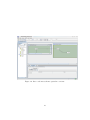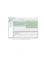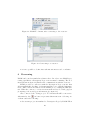
1
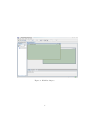
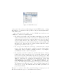
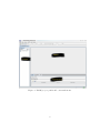
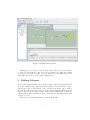
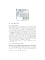
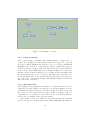
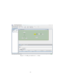
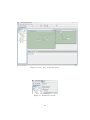
ICOM
Intelligent COnceptual Modelling Tool
version 3.0.0
User Manual
http://www.inf.unibz.it/∼franconi/icom/
March 31, 2009
1
Contents
1 Overview
3
2 Installing and Launching ICOM
4
3 ICOM general workspace
5
4 Working with Projects and Schemas
5
5 Editing Schemas
5.1 Basic Interaction . . . . . . . . . .
5.1.1 Point and drag . . . . . . .
5.1.2 Adding and removing items
5.1.3 Input prompting . . . . . .
5.1.4 Selecting items . . . . . . .
5.2 Class . . . . . . . . . . . . . . . . .
5.3 Association . . . . . . . . . . . . .
5.4 Attribute . . . . . . . . . . . . . .
5.5 Role . . . . . . . . . . . . . . . . .
5.6 IsA relationship . . . . . . . . . . .
5.7 Axiom . . . . . . . . . . . . . . . .
5.7.1 Node Definition . . . . . . .
5.7.2 Equivalence Axiom . . . . .
5.7.3 Disjointness Axiom . . . . .
5.7.4 Subsumption Axiom . . . .
.
.
.
.
.
.
.
.
.
.
.
.
.
.
.
.
.
.
.
.
.
.
.
.
.
.
.
.
.
.
.
.
.
.
.
.
.
.
.
.
.
.
.
.
.
.
.
.
.
.
.
.
.
.
.
.
.
.
.
.
.
.
.
.
.
.
.
.
.
.
.
.
.
.
.
.
.
.
.
.
.
.
.
.
.
.
.
.
.
.
.
.
.
.
.
.
.
.
.
.
.
.
.
.
.
.
.
.
.
.
.
.
.
.
.
.
.
.
.
.
.
.
.
.
.
.
.
.
.
.
.
.
.
.
.
.
.
.
.
.
.
.
.
.
.
.
.
.
.
.
.
.
.
.
.
.
.
.
.
.
.
.
.
.
.
.
.
.
.
.
.
.
.
.
.
.
.
.
.
.
.
.
.
.
.
.
.
.
.
.
.
.
.
.
.
.
.
.
.
.
.
.
.
.
.
.
.
.
.
.
.
.
.
.
.
.
.
.
.
.
.
.
.
.
.
9
10
10
10
11
11
12
12
12
14
14
15
15
17
17
17
6 Reasoning
20
7 Visualization
21
8 Other configuration options
23
9 Limitations and Known Bugs
24
10 Contact Details
24
A DLR Syntax
24
2
1
Overview
ICOM is an advanced CASE tool, which allows the user to design multiple
extended Entity-Relationship (EER) diagrams. Each diagram can be organized into several schemas, with the possibility to include inter- and intraschema constraints. Complete logical reasoning is employed by the tool to
verify the specification, infer implicit facts, devise stricter constraints, and
manifest any inconsistency. ICOM is fully integrated with a very powerful description logic reasoning server which acts as a background inference
engine.
The conceptual modelling language supported by ICOM can express:
• the standard Entity-Relationship data model, enriched with IsA links
(i.e., inclusion dependencies), disjoint and covering constraints, full
cardinality constraints, and definitions attached to entities and relations by means of view expressions over other entities and relationships
in the schema;
• rich class of (inter-schema) integrity constraints, as inclusion and equivalence dependencies between view expressions involving entities and
relationships possibly belonging to different schemas.
The tool supports multiple schemas with inter-schema constraints but it
turned out to be extremely useful also in supporting the conceptual modelling of “classical” databases involving a single rich schema with integrity
constraints, and in designing ontologies for various purposes.
ICOM reasons with (multiple) diagrams by encoding them in a single
description logic knowledge base, and shows the result of any deductions
such as inferred links, new stricter constraints, and inconsistent entities or
relationships. Theoretical results guarantee the correctness and the completeness of the reasoning process. To the best of our knowledge, this is
the first implemented tool for EER conceptual modelling with a provably
complete inference mechanism for consistency checking and for deduction –
i.e., derivation of implied links and constraints in the schema. Completeness
of reasoning means in this context that no valid deduction is left out by the
inference engine. This of course holds for the full data model employed by
ICOM, which is much richer than EER. The system employs the DLR/SHIQ
description logic to encode the schemas and to express the views and the
constraints.
The tool allows for the creation, the editing, the managing, and the
storing of several interconnected conceptual schemas, with a user friendly
graphical interface. The ICOM tool is written in standard Java 5.0, and
it is being used on Linux, Mac, and Windows machines. ICOM communicates via the DIG protocol with a description logic server. Experiments with
ICOM show that it is able to handle very large schemas, such as the integrated Conceptual Data Warehouse Model of a national European telecom
3
company. ICOM provides an interface for importing and exporting schemas
in UML-XMI class diagrams format. An new version of ICOM handling
UML class diagrams is under development.
The intention behind ICOM is to provide a simple, freeware conceptual
modelling tool that demonstrates the use of, and stimulates interest in, the
novel and powerful knowledge representation based technologies for database
and ontology design. In particular, we are interested to cooperate with
researchers and companies considering the opportunity to incorporate these
technologies in their tools.
For more details about the theory behind ICOM, and in particular about
the proper use of the DLR view language please refer to:
• Enrico Franconi and Gary Ng (2000). The ICOM Tool for Intelligent
Conceptual Modelling. 7th Intl. Workshop on Knowledge Representation meets Databases (KRDB’00), Berlin, Germany, August 2000.
• Diego Calvanese, Giuseppe De Giacomo, Maurizio Lenzerini, Daniele
Nardi, and Riccardo Rosati (1998). Description Logic Framework for
Information Integration. In Proc. of the 6th Int. Conf. on the Principles of Knowledge Representation and Reasoning (KR’98). 1998.
• Pablo Fillottrani, Enrico Franconi, Sergio Tessaris (2006). The New
ICOM Ontology Editor. 2006 International Workshop on Description
Logics, Lake District, United Kingdom. May 2006.
At the ICOM home page http://www.inf.unibz.it/∼franconi/icom/
you can find a detailed on line tutorial on ICOM.
2
Installing and Launching ICOM
A Linux, MacOSX, or Windows machine is required, with Java 5.0 compatible virtual machine previusly installed . ICOM comes as a standalone folder,
to be copied anywhere in the hard disk. A Description Logic resoning server
supporting the DIG protocol needs to be installed as well, in order to be
able to make deductions. After the installation, you will find an executable
file “ontoeditor” in the top level directory; execute it (either the .bat or .sh
extension, depending on your platform), and the system will be launched.
The “ontoeditor” file runs only the editor; it does not start the reasoning
component. The reasoner server must be independently launched before or
after launching ICOM.
This is a step list for installing and running ICOM:
1. install a Java 5.0 compatible virtual machine (for example Sun JRE
5.0 at http://java.sun.com/javase/downloads/index jdk5.jsp)
4
2. install a Description Logic server accepting DIG connections (for example RacerPro at http://www.racer-systems.com/)
3. download ICOM executable files from the ICOM home page
http://www.inf.unibz.it/∼franconi/icom/ontoeditor.zip
4. unzip the file ontoeditor.zip into a new directory in the system.
5. execute the Description Logic reasoning server.
6. execute ICOM, by running either the ontoeditor.sh file on Linux
and MacOS, or the ontoeditor.bat file on Windows.
3
ICOM general workspace
All features of ICOM can be accessed via the menu bar. In addition, a
toolbar is provided with the most frequently used functions. Toolbar buttons
are grouped according to their functions. Context menus are also available
for a quick access to operations related to the current mouse pointer position.
Figure 1 shows the general layout of components in the ICOM workspace.
ICOM allows the user the work simultaneously with several projects.
Each project has a tab in the ICOM workspace below the toolbar. For
each project there is a desktop panel, a browser, and the properties panel.
The desktop panel is the place where the several schemas in the project are
represented. Each schema has its own window within this desktop. Editing
operations such as adding, moving, editing and deleting classes, associations
and axioms can be performed in the schema window. These windows are
zoomables, allowing to represent ontologies with large number of components. The browser panel describes the hierarchy of elements available in
each project. The top elements in this hierarchy are the schemas; classes
and association appear as children of their schemas. The properties panel
is dependent on the current selected object in the current schema window
on the desktop. It shows several tabs with additional information about
this object. The user is allowed to view and edit this information. Detailed
information about these panel is given in next section.
4
Working with Projects and Schemas
An ICOM project consists in a set of possibly related EER schemas. Schemas
are composed by a set of items like classes and relations, and also nonstandard EER constructs such as axioms. In order to start working with
ICOM you have to create a project, or load an existing one. The File menu
and its submenus (see figure 2) provide a number of items relating to the
creation, loading, opening, saving and closing of projects and schemas. They
5
Figure 1: ICOM workspace.
6
Figure 2: ICOM File menu.
can be saved and read as text files using an internal XML format, or using
the DIG protocol syntax. It is also possible to import class diagrams in the
UML XMI format.
As soon as a project is created or loaded, ICOM enters in the project
editing mode, and a set of panels appear:
• the desktop panel at the centre is a desktop panel where you can work
with the schemas included in the current project. Within this desktop
each schema is represented as a window, which can be moved, resized,
closed, iconified and deiconifed. Associated to every item appearing
in this panel there is a contextual menu with the most frequently used
functions on it. These menus are activated with a right click on the
graphical representation of the object.
• the browser at left shows the hierarchy of elements in the current
project. You can use this panel to quickly locate any element in the
editing panel, either by clicking on its name in the tree or by using the
search function at the bottom of the panel.
• the properties panel at bottom shows and allows the user to edit information about the currently selected object in the editing panel. If
none is selected it shows information about the current project. This
information is divided into four tabs: Data, Metadata, Definition and
DIG tab. The Data tab contains the information and options that
characterizes the object within the project. The Metadata tab contains multilingual represention of object information external to the
project, like authoring, natural language description and versioning.
The Definition tab allows the user to introduce DLR definitions for
some type of objects. The DIG tab shows the DIG representation of
projects and schemas.
In figure 3 you can see these three panels describing an empty project, at
the moment when the project contextual menu is activated.
7
Figure 3: ICOM project panels and contextual menu.
8
Figure 4: ICOM schema panels.
Multiple projects can be opened at the same time, but objects cannot
be moved between them - only one project is visible at a time and editing
of each project is independent. You can switch between different projects
using the tabs at the bottom of the editing panel.
5
Editing Schemas
Most of the schema editing is done in the desktop, where each schema in the
project is displayed in a separate schema window, an independent component in the desktop. In addition, some options about items can be defined
through the different tabs at the properties panel, and the different items
in the related context menu. Figure 4 shows the ICOM window with two
schema panels. The currently selected schema window is always shown with
a yellow border.
There are several fundamental operations in ICOM.
9
Figure 5: ICOM Insert menu.
5.1
5.1.1
Basic Interaction
Point and drag
The left mouse button is used for most interactions. In the neutral state, all
items in an ICOM schema are selectable. Yellow color is used to show the
selected items. For example, concept Class2 from schema UntitledSchema2
is selected in figure 4. The properties panel is automatically updated so as
to show and edit the information about the selected item. This item can be
moved, dragged, and placed anywhere within the schema window. Clicking
on the
will switch ICOM from any editing state into the neutral state.
Double clicking on items with name (like classes and associations) will
open a type-in box that allows renaming the item. Pressing the return key
will confirm the new name, while clicking outside this textfield keeps the
current name without any change. Please use only ALPHA-NUMERICS
characters in all names. This includes project and schema names, as well as
all classes, associations, roles and field names. The schemas are saved with
all cases preserved in names, but ICOM is case insensitive.
The right mouse button is used to pop up the contextual menu associated
with the pointed item.
5.1.2
Adding and removing items
Items can be created by clicking the desired button in the toolbar, selecting
the desired entry under the Insert menu or the schema context menu (see
below for a detailed description on creating different types of objects). Figure 5 shows the ICOM Insert menu items. Objects can be removed by first
selecting the object to be removed, then select Cut from the Edit menu, the
schema context menu, or the
toolbar button.
10
Figure 6: Prompting for a class.
5.1.3
Input prompting
Most object-creating operations require further inputs to complete the operation. For example, two user-specified classes are required to create an
association. When ICOM is expecting an object to be selected, ICOM will
highlight in blue only those objects that are allowed. Additionally, the type
of the item and the operation being performed is described in the status bar
at the bottom of the ICOM window. For example, in figure 6 we can see the
interface at the moment in which we are creating an isa relationship, and
the parent class is expected to be selected. All classes in the current project
are shown with a blue border, and the status bar shows the respective message. We can see also in this example that ICOM semantics considers all
associations also as classes.
5.1.4
Selecting items
Just clicking on the graphical representation of an item makes it the currently selected item. Classes, associations, roles, isa relationships, even single links from axioms and isas are selectable in this way. The browser can
also be used to select classes and association, either by clicking on the tree
representation or by using the search function. Projects and schemas are
selected also by clicking on the respective panels.
It is possible to select a set of items. You can add an item to the currently
selected set just by selecting single items while maintaining the shift key
11
pressed, or by including them in a dragging rectangle. The selected group
of items can be used as arguments for the visual functions (see section 7),
for multiple deletion, or for moving the whole group just by dragging one of
the selected items.
5.2
Class
To create a class in a schema, select the associated menu item in the Insert
menu or the schema context menu. The new class will be created with
automatically generated name and position. Note that classes of the same
name in different schemas are considered different.
When a class is selected, the Data tab in the properties panel allows
the user to change the class name, and to create/delete attributes. The
Definition tab is activated to introduce a DLR expression that constraints
this class.
5.3
Association
An association can be created by selecting the associated menu items. There
are two ways of creating associations. The Insert menu item and the schema
context menu allows the user to create a new 0-ary association. An association thus created will not be related to previous elements in the schema.
In the class and the association context menu we have the option to create
a new binary association. Upon selecting this item ICOM will prompt for
another class, which will be related to the new association together with
the currently selected class or association. This allows binary associations
to be created. N-ary relations can be created in conjunction with the use of
the enroll menu items also available in the concept and association context
menu. In this case, ICOM will prompt in blu existing associations in order
to select one.
Similar to classes, associations of the same name in different schemas are
considered different. Also, when an association is selected, the Data tab in
the properties panel allows the user to change its name, and to create/delete
attributes in it. The Definition tab is activated in the properties panel to
introduce a DLR expression that constraints this association.
5.4
Attribute
Every entity and relation may have many attributes. Clicking on
in
the Data tab within the Properties panel when the class or association is
selected of the will add a new row in the related field table. This row
includes columns for the attribute name and the domain datatype, together
with several metadata columns for the new attribute. Figure 7 shows the
Data tab panel while creating an attribute.
12
Figure 7: Adding an attribute to a class.
13
Similar to classes, attributes of the same name in different schemas are
considered different. Attributes of the same name within the same schema
represent the same attribute, even if defined in different classes or associations.
The domain of an attribute is indicated in the column after its name.
To change the domain, just type the new datatype name in this field. There
does not exist a predefined set of domains. They are represented simply
as strings. Unlike classes and associations, domain has a global context.
Domains of the same name in different schemas are considered the same
domain.
Attributes can be deleted from a class or an association by selecting the
respective row in the field table at the Data tab panel, and then clicking on
the
5.5
button.
Role
By default roles are created with a relation, one on each side of the binary
relation. N-ary relations can be created by adding roles to a relation. These
operations are described in 5.3.
A role is the binary relationship between two objects. In ICOM, role is
used to denote the connection of an entity to a relationship. It is also used
to express the cardinality constraints of an entity in a relation. A role may
have two constraints: Totality, or the minimum cardinality, reflects participation; while uniqueness represents the maximum cardinality. A minimum
cardinality of 1 indicates all instances of an entity must participate in the
relationship at least once. A maximum cardinality of 1 indicates all instances of an entity can only participate once in the relationship (unique).
When a role is selected, two checkboxes are enabled in the respected Data
tab panel to reflect the constraints of the relationship respectively. Selecting
the boxes changes the constraints applied. The table in figure 8 shows the
possible combinations of constraints and their visual representation.
5.6
IsA relationship
You can specify that one class is a subclass of another by creating an Isa
relationship. This can be done with the associated Insert menu item, or
several context menu items. The options in the Insert menu and the schema
context menu prompt for two objects (classes or associations), the first one
is the subclass, the second one being the super-class. Classes can only be a
subclass of classes, and associations can only be a subclass of a associations.
In the class and association context menu, there are also another two items
for creating new Isa relationship. You can create ta new Isa with the current
class/association playing the parent role, or the child role. In each case
14
Minimum Cardinality
Maximum Cardinality
0
1
0
n
1
1
1
n
Visual Representation
Figure 8: Cardinality constraints for roles in ICOM.
ICOM will prompt for another class/association for the correspondent role
in the Isa relationship.
You can add additional descendent objects to a subsumption relationship
with the compose isa menu item also available from the class and association
context menu. In this case, the currently selected class/association will be
the new child in a previously existing Isa relationship.
By default, an Isa node only specifies that a set of objects is the subclasses of another object, but nothing more. Similar to roles, Isa node can
be further customised using checkboxes in the respective Data tab panel.
Totality expresses that the super-class object is a union of all subclasses
(covering). While exclusiveness expresses that all subclasses may be disjoint (mutually exclusive) from each other. There is a different graphical
representation for regular, total, exclusive and total-exclusive isa relationships defined in this way.
IsA relationships can be removed in the same way as classes and associations, with the
5.7
function.
Axiom
In addition to the above constructs, ICOM allows intra- as well as interschema axioms to be expressed. There are four types of axioms: node
definition, equivalence, disjoint and subsumption.
5.7.1
Node Definition
Each class and association can be fully defined by means of a view expression:
the view completely defines a particular object that cannot be expressed by
the EER diagrammatic constructs alone. This is done by using a view
language based on the DLR description logic[]. The view expression must
be entered in the Definition tab panel that appears when the class or the
15
Figure 9: Adding a view definition to a class.
association is selected. Figure 9 shows the interface at the moment of giving
a definition for a class.
A definition has a global context, meaning it can express inter-schema
relationships as well as intra-schema relationships. The particulars of the
DLR syntax are included in one appendix. The view language includes two
syntactic sorts: one for entities and one for relationships. Full boolean operators are allowed, plus a selection operator (selecting tuples in a relationship
with a specific entity type in some named role argument) and a unary projection operator (projecting a relationship over a named role argument). A
generalised projection operator with cardinality restrictions is available as
well. Examples of the use of the DLR language as a view definition language
in ICOM can be found at the ICOM home page
http://www.inf.unibz.it/∼franconi/icom/.
Since a definition can refer to objects in different schemas, a name-prefix
is used in definitions to distinguish objects with the same name but from
different schemas. The name-prefix used is the schema’s name followed by
16
a slash, the type of the item (class or association) and the sharp ] symbol.
For example, Class1 in Schema1 and Class1 in Schema2 would be referred
to as Schema1/Class]Class1 and Schema2/Class]Class1 respectively.
There is a feature in ICOM to make life easier in typing node names
within definitions. In the contextual menus of classes and associations there
is the ”Copy name” item, which once selected will copy the name a clipboard.
This name can be recovered through the ”Paste name” menu item in the
contextual menu at the Definiton tab panel.
Classes and associations with a view definition are shown with (+) appended to their names in the editing panel. See figure 9.
5.7.2
Equivalence Axiom
Any two classes or two associations in any schema can be made equivalent
semantically. Select the related Insert menu item, and ICOM will prompt
you for two items in succession that will be declare equivalent, either in
the same or in different schemas. Figure 10 shows the visual representacion
of inter- and intra-schema equivalence axioms. Several context menu also
contains options for creating equivalence axioms.
It is possible to add a class to an existing inter-schema equivalence axiom
using the compose axiom button, or the associated Edit menu item. Equivalence axioms can be removed in the same way as classes and associations,
with the
5.7.3
function.
Disjointness Axiom
Any two classes or two associations in any schema can be said to be disjoint
from each other. Select the related Insert menu item, and ICOM will prompt
you for two items in succession that will be declare equivalent, either in the
same or in different schemas. Figure 11 shows the visual representacion of
inter- and intra-schema disjoint axioms.
It is possible to add a class to an existing inter-schema disjoint axiom
using the associated Insert menu item. Disjoint axioms can be removed in
the same way as classes and associations, with the
5.7.4
function.
Subsumption Axiom
Any two entities or two relations in any schema can be said to include one
or the other. This is done with the Insert menu item, and also with the
class/association context menu item, which also works relating classes in
different schemas. There are two limitations on inter-schema subsumption
axioms, in comparison with intra-schema Isa relationships:
• inter-schema subsumption axioms are always binary. No composition
is available for this kind of axiom.
17
Figure 10: Inter- and intra-schema equivalence axioms.
18
Figure 11: Inter- and intra-schema disjoint axioms.
19
Figure 12: ICOM Tool menu, after connecting to the reasoner.
Figure 13: Connecting to a reasoner.
• it is not possible to define inter-schema axioms as total or exclusive.
6
Reasoning
ICOM can be used as standalone schema editor. In order to use ICOM’s reasoning capabilities, a Description Logic reasoner must be running. The Tool
menu (shown in figure 12) handles the communication with the reasoner.
ICOM provides a connection with the Description Logic reasoner that
allows satisfiability checking of schemas and discovery of implied subsumptions. This connection is made via the HTTP protocol using the DIG syntax. When the connect to a reasoner menu item is selected, a dialog appear
prompting for host and port information (see figure 13)
Once connected, the ”Verify project” Tool menu item will become active.
Alternatively, the
bar button represents this menu item. Selecting one
of them causes the following:
• the current project is translated to Description Logic by ICOM. Then
20
this is transmitted to the reasoner.
• each class and association in the project is checked for satisfiability.
• for each class and association in the project, its equivalent peers, and
super-classes (according to the classifier) are determined.
• for each class-role-association triple, check its stricter minimum and
maximum cardinality.
After the verification process, several modifications to the schemas may
be observed:
• all unsatisfiable items will appear in red in the schemas. An unsatisfiable item means that the item describes an empty set of instances and
can never have any instances.
• several additional implications will appear in green:
– all deduced semantically equivalent objects are connected with
equivalent axiom links.
– all deduced inclusive relationships between objects are connected
with subsumption axiom links.
– all roles whose cardinalities are determined more restrictive than
originally specified.
Finally, in the status bar, you will see a line that reads either: “Project
is satisfiable”, “Project contains some unsatisfiable term”, or “Project is
unsatisfiable”. This indicates the overall validity of the project.
At this point, if we elect to Discard deductions, by selecting the respective Tool menu item, the entire project will be returned to its original state
(and any information about unsatisfiability will be discarded). Performing
another schema edit will also discard the deductions before the editing is
carried out. Alternatively, the equivalence, subsumption relation, and role
cardinality deductions can be added permanently to the project through
Commit deductions, using the Tool menu item. There is currently no undo
function, while to undo Discard deductions is simply to redo the reasoning,
there isn’t an undo equivalent for Commit deductions, so always save your
schemas/projects regularly.
7
Visualization
Complex schemas with several classes and associations can be zoomed out
in order to improve presentation. By dragging to the left while the shift key
is pressed, the representation of the schema panel is zoomed out (see figure
21
Figure 14: A zoomed out schema panel.
Figure 15: ICOM View menu.
22
14). On the contrary, dragging to the right while pressing the shift key will
cause the schema panel to zoom in.
ICOM also provides several functions that help in obtaining a better
visual representation of the current schema. These functions are available
in the View menu, seen in figure 15. These function can be classified into
two groups: layout functions and visual filters.
Layout functions automatically rearrange the position of the items in
the schema, possible changing also the zooming state of the window. There
are four possible layout functions:
• the
zoom in option zooms in the schema panel maximizing the
visualization of the selected items.
• the
zooms out the schema panel in order to allow the visualization
of all their items
• the automated layout rearranges the position of items. This option is
currently not implemented.
• the
select neighbors function adds to the set of selected items all
items directly connected to the currently selected ones
• the
anchor function fixes the position of the selected items, so
as future execution of layout functions will not affect their current
position. The background color of the anchored item will change to
red. Selecting this function again on the same node will un-anchor it.
Visual filters allows you to show/hide some details from the schema
representation. When they are activated, the information is not shown in
the panel. This is represented as a checked menu item. When the filters
are out, the information is shown in the panel, and the menu items are
unchecked. There are three visual filters:
• the fields filter
hides fields data in the editing panel
• the roles filter hides roles names in the editing panel. Cardinality
constraints visual representation is not affected by this filter.
• the constraint filter hides visual representation for equivalence and
disjoint axioms in the desktop.
Axiom filter apply not only to existing axioms, but also to deduced ones.
8
Other configuration options
Some operations of the editor will cause logging information to be recorded.
This logging information can be viewed using ”Show logging info window”
under the Help menu.
23
9
Limitations and Known Bugs
• copy/paste functions are not available.
• no undo/redo functions are not available.
• layout function is currently not implemented.
• it is not possible to add/delete metadata fields.
• on MacOS, selecting nodes when prompting from context menus does
not work properly.
• on some MacOS, CPU usage increases abnormally when drawing interschema axioms.
10
Contact Details
The home page of ICOM is at
http://www.inf.unibz.it/∼franconi/icom/
If you experience problems with ICOM, contact [email protected].
Please supply as much information as you can about the problem (the version
and the build numbers, what you were doing when the problem occurred
and so on). For any other question related to ICOM, please contact Enrico
Franconi at [email protected]. Ideas, comments and cooperation
proposals are welcome! The main developers of current version of ICOM
are Enrico Franconi (project leader), Pablo Fillottrani, Juan Heguiabehere
and Sergio Tessaris. ICOM v1.1 was developed by Enrico Franconi and Gary
Ng.
A
DLR Syntax
< entity > := < entity − name > | not < entity > |
and < entity > + | or < entity > + |
project < role − name >< relation > |
atleastr < number >< role − name >< relation > |
atmostr < number >< role − name >< relation >
< relation > := < relation − name > | not < relation > |
and < relation > + | or < relation > + |
select < role − name >< entity >
24