1
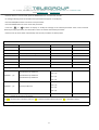
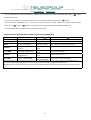
Via L.. Da VINCI, 100, 50028, Tavarnelle V.P – FIRENZE – Tel. +39 055 80 71 267 /118 Fax. + 39 055 80 71 338
E‐mail [email protected] www.telegroup.it
POWER FACTOR CORRECTION SYSTEMS
USER MANUAL
Automatic Power Factor Correction panels Pages 2 – 4
Microprocessor PFC Controller
Pages 5 – 14
1
Via L.. Da VINCI, 100, 50028, Tavarnelle V.P – FIRENZE – Tel. +39 055 80 71 267 /118 Fax. + 39 055 80 71 338
E‐mail [email protected] www.telegroup.it
GENERAL INFORMATION
Attention!!! Proper connection and start‐up of power factor correction equipment is relatively simple yet it must not ever, under
any circumstances, be left up to chance. Consequently, the device will not engage or disengage the batteries of capacitors or it
will operate anomalously. In that these panels have all been tested and inspected by the manufacturer, any anomalous
operation will be due to faulty connections, and in particular or to a faulty positioning of the current transformer. Therefore, we
kindly request that you observe the instructions in this manual and rigorously follow them in the sequence indicated. Thank you
for your kind attention and collaboration.
Locate the panel in a well aerated space and far from any heat sources: good air circulation is one of the most important factors
for proper and long lasting operation. Leave at least 30 cm of space around the panel, so that air may freely enter and exit the
area. Do not locate the equipment in humid areas unless it has been specifically requested with a particular protection grade.
1‐ LOCATION OF THE EQUIPMENT
Operational limits:
-
Relative humidity: max 50% at 40° C – 90% at 20° C
-
Altitude: max. 2000 metres a.s.l.
-
Transport and warehousing: temp.‐25 to +55° C
2‐ CURRENT SHORT CIRCUIT
To insure that the equipment will not be subject to short circuits it is necessary to install, upstream of the power factor
correction panels, whether they are fixed or automatic, a circuit of three aM NH type current limiting fuses (or other devices
with similar characteristics) with suitable nominal current specifications and power to break the circuit above the presumed
short circuit current.
When the LCC is not known at the point of installation, it may be approximated by the LCC of the transformer (50 KA).
KVAR power
From 7.5 to 17.5
From 20 to 27.5
From 30 to 60
From 65 to 150
From 100 to 150
From 160 to 360
From 200 to 350
From 400 to 1000
From 100 to 125
From 150 to 175
From 200 to 350
From 400 to 500
From 550 to 1000
LCC max kA
4
5
6
10
16
20
20
40
10
16
20
40
50
KVA
50
63
100
160
200
250
315
400
500
630
800
1000
1250
1600
2000
V DC%
4
4
4
4
4
4
4
4
4
4
6
6
6
6
6
LCC kA
1.8
3.6
5.77
7.22
9.02
11.37
14.43
18.04
22.73
19.25
24.06
30.07
38.49
48.11
50.14
2
Via L.. Da VINCI, 100, 50028, Tavarnelle V.P – FIRENZE – Tel. +39 055 80 71 267 /118 Fax. + 39 055 80 71 338
E‐mail [email protected] www.telegroup.it
3 ‐ CONNECTION
1. The C.T. secondary must be earthed.
2. Power the equipment with cables of a section suitable for the label power specifications.
3. Power Supply: Three phase with neutral for equipment with a power from 7.5 to 27.5 kvar ‐ Three phase without neutral
for equipment over 27.5 kvar with a power of 400 volts.
4. Anchor the power supply cables to the mains switch.
IMPORTANT!
In the event that the panel were to be shut down during operation, make sure that all of the batteries have been disengaged before
opening the mains switch.
4‐ CHOICE, LOCATION AND CONNECTION OF THE CURRENT TRANSFORMER (CT):
C.T. calibration with 5/A secondary, (to be provided by the client) must be calculated based on the average current circulating in the
plant, independent of the power factor correction, keeping in mind that the range of measurement of the regulator current goes
from 8% to 110% of the C.T. current. Therefore, this condition must be satisfied.
Ex: there is a circulating current of 200/A; a C.T. must be chosen the current of which is between: 2500 A (8% of 2500=200/A) and
180A (110% of 180 A= 200 /A). It is a good rule to install a C.T. with twice the primary current of that which is actually circulating.
The C.T. must be located upstream of the loads and the bypass that
powers the power factor correction panel. All in all one must “consider”
MAINS
L1 L2 L3
both the inductive loads of the users as well as those of the capacitance
of the capacitors. In the bypass that powers the power factor correction
T.A..../5 A
panel, the phase corresponding to that where the C.T. is installed must
be anchored to the central terminal of the switch. Since the phases that
voltmetrically power the regulator must be different from the phase
where the C.T. is installed and in that in our panels this signal is drawn on
the two lateral phases, it is obligatory that the corresponding phase be
T.T.
anchored, to the same one where the C.T. was installed, on the central
terminal of the switch. This condition may be easily verified with the use
QUADRO RIFASAMEN TO
of a voltmeter, measuring, between the phase where the C.T. was placed
and the phase anchored to the central terminal of the switch of the
LOAD
automatic power factor correction panel: the voltage must be “0”. The
location of the C.T. is fundamental for the proper use of the equipment.
The relative diagram is found in the figure to the side.
In the table below some possible positions of the
MAINS
C. T.s that are faulty:
L1 L2 L3
3
Via L.. Da VINCI, 100, 50028, Tavarnelle V.P – FIRENZE – Tel. +39 055 80 71 267 /118 Fax. + 39 055 80 71 338
E‐mail [email protected] www.telegroup.it
Position 2: Even though the C.T. has been installed upstream,
the corresponding phase that powers the device is not anchored
to the central terminal.
Position 3: The C.T. has been installed on the load line!
Position 4: the C.T. has been installed on the lines that power
the power factor correction panel.
CONTATORE
DI CORRENTE
MAINS
L1 L2 L3
T.A..../5 A
It is often found, particularly in installations of low power
equipment located near an ENEL meter in L.V., that the power
supply line to the loads coincides with that which powers the
power factor correction panel.
In this specific case, both power supply cables must be inserted
in the hole for the C.T., (for the power factor correction and for
the loads) See the figure.
T.T.
QUADRO RIFAS AMENTO
LOAD
Insertion of an automatic power factor correction panel in presence of an M.V. transformer: in the event that there are capacitor
banks of the fixed type, on the transformers, the C.T. necessary for the command of the automatic power factor correction device
must be positioned downstream of the fixed capacitors.
4
Via L.. Da VINCI, 100, 50028, Tavarnelle V.P – FIRENZE – Tel. +39 055 80 71 267 /118 Fax. + 39 055 80 71 338
E‐mail [email protected] www.telegroup.it
The figure above illustrates the connection of an automatic power factor correction device in presence of M.V. transformers
connected in parallel.
It is necessary to use a C.T. adder with 2 or 3 inputs according to whether there are 2 or 3 transformers, to which the output cables
from the C.T. must be connected. The C.T. adder output must be connected to the automatic power factor correction panel.
Set the C.T. primary (the methods for setting this parameter are described below) as the sum of the two C.T.s.
PFC MICROPROCESSOR CONTROLLER
1.
Attention The PCRK5 microprocessor regulator has
already been pre‐set and must not under any
circumstances be changed. The only parameter to
set by the installer is the value of the primary for
the Current Transformer (C.T.).
2.
Once the device has been powered, the display will
show: “CT “ (Current Transformer) flashing.
3.
Pressing
or
directly set the value of the
C.T. primary.
4.
Once the setting has been made, press MAN/AUT to
confirm. The device will memorise the setting and
will start back up again in automatic.
5.
For all of the PCRK settings and visualisations, see
the relative instructions in this manual.
5
Via L.. Da VINCI, 100, 50028, Tavarnelle V.P – FIRENZE – Tel. +39 055 80 71 267 /118 Fax. + 39 055 80 71 338
E‐mail [email protected] www.telegroup.it
DIAGRAM FOR THREE PHASE INSERTION
Attention!! The C.T. position is on the “T” phase, whilst in our automatic panels it must be on the “S” phase.
6
Via L.. Da VINCI, 100, 50028, Tavarnelle V.P – FIRENZE – Tel. +39 055 80 71 267 /118 Fax. + 39 055 80 71 338
E‐mail [email protected] www.telegroup.it
PCRK5 ‐ PCRK7 ‐ PCRK8 ‐ PCRK12 AUTOMATIC POWER FACTOR REGULATORS
ATTENTION!
These devices must be installed by qualified personnel, with respect for the regulations in effect for plant facilities
installations, so as to avoid any damage to things or persons. The products described in this document may be changed or
improved at any time. The descriptions and data in this document cannot therefore be of any contractual value
DESCRIPTION
– Microprocessor for automatic power factor regulator
– LED Display with 3 number 7 segments.
– 4 button membrane keypad.
–TTL‐RS232 serial Interface for automatic set‐up and test inspection with a PC.
– Internal temperature sensor
– Advanced functions (capacitor overload current measurement, average weekly power factor, memorisation of maximum
values.
– 2 programmable relays as alarms and/or ventilation control
VERSIONS
PCRK5 container 96x96mm, 5 steps
PCRK7 container 96x96mm, 7 steps
PCRK8 container 144x144mm, 8 steps
PCRK12 container 144x144mm, 12 steps
INSTALLATION
– For three phase activation the C.T. must be connected to the phase not used for powering the device, as indicated in the
connection diagram.
– The device is supplied ready to recognise the direction of the C.T. current. In the case of a cogeneration plants it is
necessary to disable this function (see chapter on advanced menu) and see to the correct connection of the C.T.
– The C.T. secondary must be earthed.
POWERING UP
– Upon commissioning, the display will show “‐‐‐‐‐‐‐ “, indicating that the setting of parameters has not yet been performed.
– In this condition, it is possible to carry out a manual test of the steps for a verification of the connections.
– Pressing the
or
buttons it is possible to activate or deactivate the steps.
– ATTENTION! In this phase the control of the steps is completely manual and the device will not perform the check on the
reconnection times so as to enable the discharge of the capacitors.
SETTING PARAMETERS
To set the parameters and render the device operative different methods may be followed:
1. MANUAL SETTING FROM THE KEYBOARD
2. QUICK SETTING FROM THE PC
3. AUTOMATIC SETTING
1. MANUAL SETTING FROM THE KEYBOARD
7
Via L.. Da VINCI, 100, 50028, Tavarnelle V.P – FIRENZE – Tel. +39 055 80 71 267 /118 Fax. + 39 055 80 71 338
E‐mail [email protected] www.telegroup.it
– With the device in manual mode, press the MODE button for 5 consecutive seconds.
– A message indicting access to the base menu parameters will appear on the display.
– Press the MAN/AUT button to access the next parameter.
– Press the MODE button to return to the last parameter.
– Press the
or
buttons to display or modify the settings of the selected parameter. After a few moments
without pressing any buttons, the visualisation returns to indicate the selected parameter.
– Exit from set‐up comes about automatically once the last parameter has been passed.
TABLE OF SET‐UP PARAMETERS
PARAMETER
DESCRIPTION
RANGE
DEFAULT
P.01
Primary C.T. current
OFF ...10.000
OFF
P.02
kvar smaller step
0.10...300
1.00
P.03
Nominal capacitor voltage
80...750V
400
P.04
Reconnection time
5...240sec
60
P.05
Sensitivity
5...600sec
60
P.06 LED1
Step 1 coefficient
0...16
0
P.06 LED2
Step 2 coefficient
0...16
0
The programming of the remaining steps, with exception of the last 2, comes about as in the previous step 1 and step 2
0...16
Penultimate step coefficient
P.06 LED… (1)
noA (2)
Penultimate step coefficient
ncA (2)
Penultimate step coefficient
0
FAn (2)
0...16
P.06 LED… (1)
noA (2)
Last step coefficient
0
ncA (2)
FAn (2)
Setting of the
cos φ desired (3)
0.80Ind...0.80Cap
0.95
(1) n… = Number of the step on the device.
(2) noA = Contact open in absence of alarm. ncA = Contact closed in absence of alarm. FAn = Ventilator control
(3) See on page 6 the chapter for the visualisation of the cos measurements and settings for the cosϕ
8
Via L.. Da VINCI, 100, 50028, Tavarnelle V.P – FIRENZE – Tel. +39 055 80 71 267 /118 Fax. + 39 055 80 71 338
E‐mail [email protected] www.telegroup.it
BASIC PARAMETERS SET‐UP DESCRIPTION
P.01 ‐ Primary current C.T.: For values over 1000, a flashing stop (comma) is visualised indicating thousands.
P.02 ‐ kvar smaller step: Nominal power in VAr of the smallest battery installed. Example: set 10 kvar
P.03 ‐ Capacitor nominal voltage: Nominal voltage (rated) of the capacitors. Example: set 440V
P.04 ‐ Reconnection time of the same step in seconds: Minimum time necessary for the batteries to discharge and then to
be ready to use again. Example: set 60 sec
P.05 – Sensitivity The sensitivity is a coefficient that enables the speed of the intervention of the regulator to be adjusted.
With a low sensitivity the adjustments are faster but with a higher number of engagements, whilst with a high sensitivity the
adjustment will be slower but operations will be saved. The sensitivity value represents the time that the regulator waits
before reacting to a request for reactive power equivalent to the smallest step. With higher requests for power the time will
be faster according to an inversely proportional criterion. Example: 60 s/step set In this case, with a smaller power bank at
10kvar ( = 10.0) and with a plant facility that requires 20 kvar to achieve the cos ( kvar = 20), the device will wait 60/2 = 30s
before starting the procedure of capacitor engagement (Signalled by the flashing of the LED AUT).
P.06 LED 1...n step Coefficients The step coefficients represent the power of each step compared to the smallest battery, the
value of which has been set with. If one step has power equal to the smallest step, its coefficient will be 1, whilst if it is
double it will be 2 etc. up to a maximum of 16. Setting 0, the step is disabled and will not ever be used by the device. The
last two steps may be programmed to function as normal steps or as alarm relays or still as ventilator controls. If the
penultimate step has been associated with a function, it is not possible to use the last step as a normal step. To select these
functions, press
until the following codes appear on the display :
noR = Alarm Normally open (contact open in absence of alarms).
ncR = Alarm Normally closed (contact closed in absence of alarms).
Fan = Ventilator control
PLEASE NOTE. For the alarms see the tables on page 12.
For ventilator controls see pages 7 and 9.
Example: With a PCRK7 installed on a panel with 6 batteries respectively of 5, 10, 20, 20, 20, 20 kvar at rated 440V and
wanting to use the last step as an alarm, the parameters will have to be set as follows:
P.02 = 5.00 (Smallest step = 5kvar)
P.03 = 440 (Rated voltage 440V)
P.06 LED 1= 001 (5 kvar = 1 time P.02)
P.06 LED 2= 002 (10 kvar = 2 times P.02)
P.06 LED 3= 004 (20 kvar = 4 times P.02)
P.06 LED 4= 004 (20 kvar = 4 times P.02)
P.06 LED 5= 004 (20 kvar = 4 times P.02)
P.06 LED 6= 004 (20 kvar = 4 times P.02)
P.06 LED 7= noA (Alarm normally open).
2. QUICK SETTING FROM THE PC
– For fast setting with a PC, it is necessary to use the specific kit, which includes the software and the connection cable. To
this end the PCRK is equipped with a communications port on its back side. – All of the parameters are viewed on the PC
9
Via L.. Da VINCI, 100, 50028, Tavarnelle V.P – FIRENZE – Tel. +39 055 80 71 267 /118 Fax. + 39 055 80 71 338
E‐mail [email protected] www.telegroup.it
monitor. The settings may be transmitted and memorised with a few simple mouse clicks. In the event that different control
units are to be set up in the same facility, it is possible to download the set‐up on a file and later reuse it, setting all of the
parameters with greatest of speed and safety.
QUICK SETTING C.T. SET‐UP
– In the case that the C.T to be used is not known at the moment of installation, it is possible to leave the current P.01
primary C.T. parameter. set to OFF and set all of the rest of the parameters.
– In this case, at the moment of installation of the plant, once the device is powered up, the display will show “ CT “ (Current
Transformer) flashing. Pressing
or
will directly set, the value of the C.T. primary. – Once the setting has been
made, press MAN/AUT to confirm. The device will memorise the setting and will start back up again in automatic.
3. AUTOMATIC SETTING
– The automatic setting of the parameters enables the device to be rendered operational without the necessity of setting
any parameters.
– To activate the automatic setting procedure starting from the MAN mode or else “‐‐‐‐‐‐‐ “
, press MODE and MAN/AUT
contemporaneously for 5 sec .
– On the display the message “ ASE “will appear (Automatic Set‐up) flashing to indicate the execution of the automatic
parameter setting. – The procedure lasts several minutes, during which the device measures the power of the connected
steps. This measurement will be continuously updated during normal operation.
– If the load on the plant varies suddenly, it is possible that it will become necessary to measure the same step several times.
In this case the procedure could last longer.
At the end of the automatic set‐up, device will prepare itself for automatic operation.
Important!
It is recommended, during the automatic setting phase, as far as possible, that the current not undergo significant variances.
With the use of the automatic settings, the device does not have any information available, such as: primary C.T. current or
rated voltage of the capacitor. Therefore there will be the following:
– The current will be displayed in percentages instead of Amperes.
– The measurements ∆kvar and ∑kvar will not be available.
– The capacitor overload measurements and protection will not be available.
– All of the relays are considered as normal batteries of capacitors. Therefore relays may not be used as alarms or ventilation
controls.
– The capacitors installed must be of a power 1, 2, 4, 8 o 16 times greater than the smallest step.
– The steps not used must be placed on the highest step numbering.
Note: If after automatic setting one accesses the parameters settings manually, the device will consider all of the parameters
present valid. All of the measurements and functions will be therefore available again .
VISUALISATION OF THE MEASUREMENTS AND SETTINGS OF THE DESIRED COSØ
– Normally the display visualises the cos φ for the plant together with the IND and CAP LED. The flashing decimal point
indicates a negative sign (energy flow inversion).
– Pressing the MODE button the LEDs V, A,
∆kvar etc., light up in sequence and the display shows the relative
measurement.
10
Via L.. Da VINCI, 100, 50028, Tavarnelle V.P – FIRENZE – Tel. +39 055 80 71 267 /118 Fax. + 39 055 80 71 338
E‐mail [email protected] www.telegroup.it
– For each LED there is an alternative function available, indicated on the front panel, viewable by pressing the
button
(the LED flashes fast).
– For some measurements a second alternative function is available viewable by pressing the
– When the LED SET COSφ lights up it is
by way of the
and the
button.
possible to set the set‐point for the cosφ desired, increasing it and decreasing it
buttons. The cosφ set may be regulated between 0.80 IND and 0.80 CAP.
– In the following table all of the functions available are summarised.
VISUALISATION OF THE MEASUREMENTS AND SETTINGS OF THE DESIRED COSØ
LEDs
V
A
Δkvar
Function
Voltage RMS
Current RMS
kvar kvar necessary to
achieve the set‐point
Average weekly power
factor (1)
Pessing
MAX Voltage Value
MAX Current Value
∑kvar (kvar plant)
Pessing
Steps necessary to achieve the set‐point
Current power
factor
MAX overload
┤├ CURR %
Overload % capacitors (2)
Overload event counter
Value
Electrical control panel
MAX Temperature
TEMP ºC
Units of measure °C or °F
Temperature (3)
Value
Decreases the
SET COSØ
Cosphi desired COSØ
Increases the value of SET COSØ
value of SET COSØ
(1) This PF value is drawn from the reactive and active energy meters over the last 7 days, and and is referred only to the
positive energy quadrants. (2) Overload current due to a harmonic voltage on the capacitor terminals.
(3) Attention!! The temperature measurement is to be considered reliable 20‐30 minutes after the device has been turned
on.
WEEK P.F.
11
Via L.. Da VINCI, 100, 50028, Tavarnelle V.P – FIRENZE – Tel. +39 055 80 71 267 /118 Fax. + 39 055 80 71 338
E‐mail [email protected] www.telegroup.it
CLEARING MAXIMUM VALUES
–
The maximum values for Voltage, Current, Overload and Temperature, as well as the average weekly power factor
may be cleared contemporaneously pressing the
and
buttons for 3 seconds. Once cleared the display
will show “ CLr “
OPERATIONAL MODES
–
The AUT and MAN LEDs indicate the automatic or manual operational modes.
–
To change modes, press the MAN/AUT button for 1 consecutive second.
–
It is not possible to change modes whilst the SET COS
–
The operational modes remain memorised even in the absence of the electrical power supply.
φ LED is lit.
MANUAL OPERATION
When the device is in manual mode it is possible to select one of the steps and to activate or deactivate it manually.
If the display is visualising a measurement different from the cosφ , press MODE until all of the LEDs for the measurement
are off.
To select a step use the
and
buttons. The step selected will flash quickly.
Press MODE to activate or deactivate the step selected.
If the selected step has not run out of its reconnection time, the MAN LED will flash to indicate that the operation has been
accepted and that it will be performed as soon as possible.
The manual step configurations remain memorised even in the absence of the electrical power supply. When the device is
powered up again, the original status of the steps is restored.
AUTOMATIC OPERATION
– In automatic mode the device calculates the best configuration of the steps to achieve the cos φ set.
– The selection criteria takes into consideration many variables such as: the power of the single steps, the number of
operations, the total time of use, the reconnection time, etc. The device indicates forthcoming activation or deactivation of
the steps with the flashing of the AUT LED. The flashing of the LED could be prolonged in cases when the activation of a step
is not possible due to the reconnection time (capacitor discharge time).
SETTINGS BLOCK
– It is possible to activate a function that impedes the change of the operational parameters, but that enables access to the
measurements.
– To lock or unlock the keyboard, press the MODE button and hold it down, press
three times, the
button twice
and then release the MODE button. The display will show “LOC“ when the keyboard is locked and “UnL“ when it is unlocked.
– When settings lock is activated the following operations are not possible:
• Switching from automatic to manual
• Access to the settings menu
• Modify the cos φ setpoint
• Clearing MAX values
12
Via L.. Da VINCI, 100, 50028, Tavarnelle V.P – FIRENZE – Tel. +39 055 80 71 267 /118 Fax. + 39 055 80 71 338
E‐mail [email protected] www.telegroup.it
When trying to perform the above‐mentioned operations the display will show “LOC“ to indicatethe lock condition.
ADVANCED MENU SETTINGS
– With the device in MAN mode, press the MODE button for 5 consecutive seconds.
– On the display will appear the message “SEt“ to indicate the base parameter menu.
– From this location, press contemporaneously
and
for 5 seconds, until on the display “AdS“ comes up to
indicate access to the parameters of the advanced menu.
– Press the MAN/AUT button to access the next parameter.
– Press the MODE button to return to the last parameter.
ADVANCED MENU PARAMETERS TABLE
PARAMETER
FUNCTION
RANGE
DEFAULT
3PH Three phase – 1PH Single‐phase
3PH
P.11
Type of Connection
P.12
C.T. connection recognition
P.13
Frequency recognition
P.14
Step power adjustment
On Enabled – OFF Disabled
OFF
P.15
Adjustment mode
Std Standard
Std
P.16
Step activation mode
Std Standard – Lin Linear
Std
P.17
Set‐point cosØ cogenerazione
OFF ‐ 0.80Ind .. 0.80Cap
OFF
P.18
Disconnection sensitivity
OFF ‐ 1..600sec
OFF
OFF Disabled – On Enabled
OFF
OFF ‐ 100...150
125
OFF ‐ 100...200%
150
P.19
P.20
P.21
Steps disconnection going to MAN
OFF
Capacitor overload alarm threshold
Immediate step disconnection
overload threshold
Aut Automatic – dir Direct – rEU
Inverse
Aut Automatic – 50H 50Hz – 60H
60Hz
Aut.
Aut.
P.22
Overload event counter reset time
1... 240h
24
P.23
Overload alarm reset time
1...30min
5
P.24
Temperature units of measure
°C Celsius ‐ °F Fahrenheit
ºC
P.25
Ventilator start Temperature
0 ... 100°C ‐ (32...212°F)
35
P.26
Ventilator stop Temperature
0 ... 100°C ‐ (32...212°F)
30
P.27
4) Temperature alarm threshold
50 ... 100°C ‐ (122...212°F)
55
ADVANCED SET‐UP PARAMETERS DESCRIPTION
P.11 ‐ Type of Connection
Select the connection three phase or single phase
13
Via L.. Da VINCI, 100, 50028, Tavarnelle V.P – FIRENZE – Tel. +39 055 80 71 267 /118 Fax. + 39 055 80 71 338
E‐mail [email protected] www.telegroup.it
P.12 ‐ C.T. connection recognition
Set on Automatic, the device works on 2 quadrants and on the powering‐up it recognises the C.T. current direction. Set on
Direct, the device works on 4 quadrantse and may be used on both standard and cogeneration plants. It is however
necessary to verify the correctness of the C.T. connection, verifying that, with the importation of energy the decimal point of
the cosφ measurement does not flash. Otherwise the C.T. connections must be reversed (terminals S1 and S2), or, more
simply, set on Inverse.
ATTENTION! Before disconnecting the S1 and S2 terminals, verify that thesecondary C.T. terminals are short circuited.
P.13 ‐ Mains frequency recognition
Automatic Selection set at 50Hz or set at 60Hz.
P.14 ‐ Step power adjustment
When this function is enabled, the device, during its normal automatic operation sees to the measurement of the power of
the steps and to change the operational parameters in the case in which the steps are worn. By way of the PC connection it
is possible to view the actual reactive power of each step.
Notes:
– When this function is being used, the time between the connection of one battery and the next is 20 seconds.
– In the case of the use of the automatic set‐up this function is enabled automatically.
P.15 ‐ Standard or Band Adjustment Mode
In Standard mode, the device adjusts the plant cos to the value set. In Band mode, the capacitors are engaged when the
plant cos is less than that set and are disengaged when it goes into capacitance. The Band mode is used to further reduce
the movements of engaging and disengaging the capacitors. Note: Setting the Band mode does not enable the setting of the
capacitive cos.
P.15 ‐ Standard or Linear engagement mode
In Standard mode the regulator freely chooses the steps according to the logic described in the Automatic Operation
chapter. In Linear mode, the steps are engaged only in progression from left to right following the number of steps, to then
be disconnected in an inverse manner, according to the LIFO logic (Last In, First Out). In case of different power steps, if the
engagement of another step causes the setpoint to be exceeded, the regulator does not engage that step.
P.17 ‐ Cos Setpoint
in cogeneration
This parameter is set when operation in the 4 quadrants is required, that is, when the plant is in a condition of consuming
and producing energy. If this parameter is set to “OFF“, the cos
φ setpoint is just one and corresponds to what has been
set with the SET COSφ LED. If instead this parameter is set to a numeric value then the setpoints become two: in normal
conditions (a plant that consumes energy from the mains,
cogeneration conditions (a plant that produces energy,
positive cosφ) the SET COSφ setting is used as setpoint, whilst in
negative cosφ) P.17. is used.
14
Via L.. Da VINCI, 100, 50028, Tavarnelle V.P – FIRENZE – Tel. +39 055 80 71 267 /118 Fax. + 39 055 80 71 338
E‐mail [email protected] www.telegroup.it
P.18 ‐ Disconnection sensitivity
With this parameter set to OFF, the sensitivity value set (see base menu) adjusts the reaction speed both in the engagement
phase and the disengagement phase. If instead P.18 is set to a different value, the value set with“P.05“ is used for
engagement, whilst the value of P.18 is used for the disengagement of the steps.
P.19 ‐ Disconnection upon passage to manual
Enabling this parameter, when going from AUT mode to MAN the steps engaged are disengaged sequentially. At the end of
the disengagement, the manual mode operates as usual.
P.20 ‐ Capacitor overload alarm threshold
By way of this parameter the A07 capacitor overload alarm threshold is adjusted. The percentage of current circulating in
the capacitors (deduced by the linked voltage waveform) is compared to this threshold. If the threshold is exceeded, after a
delay, an alarm is generated and the steps are disconnected.
P.21 ‐ Immediate step disconnection overload threshold
When the overload measured exceeds the value set with P21, the disconnection of the capacitors is immediate and the A07
capacitor overload alarm is generated. Note: The delay time of the A07 capacitor overload alarm works in an inversely
proportional manner to the entity of the overload, compared to the thresholds defined with P.20 and P21. When the
overload is less than the P.20 threshold, the alarm is not generated. When the overload is equal to P.20, the delay time is
equivalent to that set for the alarm (3 minute default with possibility of changing it through the PC). As and when the
overload increases, the delay time becomes proportionally shorter, until it is reduced to zero once the value defined by P.21
is achieved. With P.20 set to OFF, there is no intervention until the P.21 value is exceeded, therefore there is an immediate
disconnection. With P.21 set to OFF the delay is always constant. With P.20 and P21 set to OFF, the capacitor overload
measurement is disabled, in the same manner as the A07 alarm. In this case, the display visualises “ ‐‐‐ “ instead of an
overload value. In the case in which the capacitor banks are equipped with protection reactances against harmonic
overload, then it is necessary to set P.20 and P.21 to OFF.
P.22 ‐ Overload counter reset time
Each time an A07 capacitor overload alarm is generated, the counter inside of the device is incremented; this may be
consulted by way of pressing
when the ┤├ CURR % LED is lit. The counter informs the user of the number of
capacitor overload events that have occurred in the last few hours defined by P.22. This parameter also defines the hours
that the number of events will remain in memory. If for the entire time set there are no events the counter will be cleared.
P.23 ‐ Overload alarm reset time
The time for which the A07 capacitor overload alarm remains active even after the overload value has dropped below the
alarm threshold.
P.24 ‐ Temperature units of measure
Definition of the units of measure Celsius or Fahrenheit used for the temperature display e for setting the thresholds
connected to this.
15
Via L.. Da VINCI, 100, 50028, Tavarnelle V.P – FIRENZE – Tel. +39 055 80 71 267 /118 Fax. + 39 055 80 71 338
E‐mail [email protected] www.telegroup.it
P.25 ‐ Ventilator start Temperature
Temperature beyond which the ventilator relay is activated (if programmed in one of the last two steps)
P.26 ‐ Ventilator stop Temperature
Temperature under which the ventilator relay is deactivated (if programmed in one of the last two steps)
P.27 ‐ Temperature alarm threshold
Temperature beyond which the A08 Overtemperature alarm is generated.
ALARMS
– When the device detects a fault situation in the plant, a flashing alarm code is displayed. Pressing any button, the display
of the alarm is momentarily ignored enabling the user to check all of the measured values. After 30 seconds without
pressing any buttons, if the alarm condition persists, the alarm code is displayed again.
– Each alarm may cause different effects, such as the intervention of the alarm relay, the immediate or delayed
disconnection of the steps, etc., according to the properties set.
–
It is possible to modify the properties of each alarm (for example, disabling it, changing its delay time or its effect)
using a PC with the specific software (code DCRK SW), which is used for the quick setting of parameters.
In the following table the alarm codes are shown with their respective meanings and their default settings.
Alarm code
Description
Enabling
Relay alarm
Disconnection
A01
Undercompensation
O
A02
Overcompensation
O
A03
Low current
O
A04
High current
O
A05
Low voltage
O
O
5s
A06
High voltage
O
O
15min
A07
Capacitor overload
O
O
O
180s
A08
Overtemperature
O
O
O
30s
A09
No voltage release
O
O
0s
O
Delay interv.
15min
120s
O
5s
120s
Notes:
1 None of the above‐mentioned alarms is retentive.
2 In MAN mode the step disconnection comes about only for Micro‐interruption‐alarm
DESCRIPTION OF THE ALARMS
A01 – Undercompensation
All capacitors engaged and cos less than setpoint
A02 ‐ Overcompensation
All capacitors disengaged and cosgreater than setpoint
A03 ‐ Low current
Current less than 2.5% of scale limit In automatic the steps are disconnected 2 minutes after the appearance of the alarm.
A04 – High current
Current greater than 120% of scale limit
16
Via L.. Da VINCI, 100, 50028, Tavarnelle V.P – FIRENZE – Tel. +39 055 80 71 267 /118 Fax. + 39 055 80 71 338
E‐mail [email protected] www.telegroup.it
A05 – Low Voltage
Voltage lower than ‐15% of the lowest rated voltage
A06 – High Voltage
Voltage higher than +10% of the highest rated voltage
A07 ‐ Capacitor overload
Current in the capacitors greater than the threshold set (see advanced set‐up P.20 and P.21).
A08 ‐ Overtemperature
Internal temperature greater than the threshold set (see advanced set‐up P.27).
A09 – No voltage release
Voltage interruption greater than 8ms
Auxiliary power supply
UE rated voltage
Operational limits
Rated Frequency
Max Electrical power absorbed
Max Electrical power
dissipated
Max Electrical power
dissipated on output contacts
Immunity from no voltage
release
Release upon no voltage
release
Current input
Nominal Current le
Range of measurement
Permanent overload
Type of measurement
Short term thermal limit
Dynamic limit value
Power absorbed
UL use specifications
Instrumentation range
Power factor setting range
Same step reconnection time
Sensitivity range
Output relay
Outputs (1)
Type of Output
Maximum current at common
contact terminal
lth rated load limit
Rated operational voltage
Max interruption voltage
Insulation Categorypursuant to
IEC/EN 60947‐5‐1 AC‐DC
Electrical duration with 0.33A,
250VAC and load type AC11
PCRK5
TECHNICAL SPECIFICATIONS
PCRK7
PCRK8
380...415 VAC (other voltages upon request)
‐15%...+10% Ue
50 or 60Hz ±1% (self configurable)
6.2VA
2.7W
PCRK12
5VA
3W
0,5W with 5A
≤30ms
≥8ms
5A (1A upon request)
0.125...6A
+20%
True RMS
10Ie for 1s
20Ie for 10ms
0.65W
Electrically powered by way of external current transformers (low voltage) 5A max
0.80Ind...0.80Cap
5...240s
5...600s/step
PCRK5
5
4 + 1 NO
PCRK7
7
6 + 1 NO
PCRK8
8
7 NO + 1 C/O
12A
5A
250VAC
440VAC
C/250, B/400
5x10⁶ man
4x10⁵ man
2x10⁵ man
B300
17
PCRK12
12
11 NO + 1 C/O
Via L.. Da VINCI, 100, 50028, Tavarnelle V.P – FIRENZE – Tel. +39 055 80 71 267 /118 Fax. + 39 055 80 71 338
E‐mail [email protected] www.telegroup.it
Electrical duration with 2A, 250VAC
and load type AC11
Electrical duration with 2A, 400VAC
and load type AC11
Environmental Conditions
Operational Temperature
Storage temperature
Relative humidity
Connections
Type of terminals
Min and max connection cable
sections
Tightening Torque
Min and max conductor
sections
Container
Version
Material
Dimensions lxhxd
Panel drilling dimensions
Protection Grade
Weight
‐20°...+60°C
‐30...+80°C
<90%
Extractable
0.2‐2.5mm2 (24‐12 AWG)
0.5 Nm (4.5LBin)
0.75‐2.5mm2 (18‐12 AWG)
Panel assembly
LEXAN 3412R Thermoplastic
144x144x62mm
138.5x138.5mm
IP41 (IP54 with protection cap)
740g
770g
SE1 GNF2 NORYL
96x96x65mm
91x91mm
IP54
440g
460g
Regulatory References
IEC/EN 61010‐1; IEC/EN 61000‐6‐2; ENV 50204; CISPR 11/EN 55011; 61000‐3‐3; IEC/EN 60068‐2‐61; IEC/EN60068‐2‐27;
(1) 1 galvanically isolated output contact
18