1
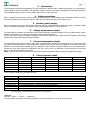
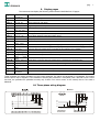
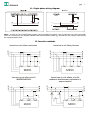
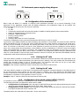
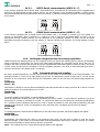
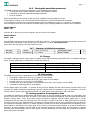
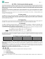
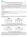
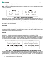
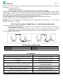
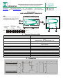
Apparecchiature elettroniche per applicazioni nel settore elettrico
Electronics equipment for electrotechnical applications
Dossena snc di Barbati Agostino & C.
Via Ada Negri, 1
www.dossena.it
26824 Cavenago d’Adda (Lodi)
E-mail : [email protected]
Italy
Tel. +39 371 4497.1
R.I. / P.I. / C.F. 00854320157
Fax +39 371 70202
R.E.A. di LODI n°604734
User manual
MIDO MEASUREMENT APPARATUS
MIDO
MIDO
1- SETUP Key for access to the configuration menu
2- Multifunction key: confirm and save configuration
data, selection of autoscroll pages
3- Scrolling pages and setting configuration values
Identifier of the
quantity and unit of
measurement
Multiplier of unit of
measurement
Value
measured
k V
k V
1
9 9
MIDO
Number
of the phase
2
9 9 9
k V
1
3
9 9 9
Page
identifier: 1, 2,..
1. Technical characteristics
Power supply
Input
Voltage measurement inputs
115/230 V AC (+15 -20) % 50/60 Hz
Max 4 VA
Nominal 440 Vrms phase-phase - Max 600 Vrms phasephase
750 Vrms for 60 sec / 900 Vrms for 1 sec
In = 5A from AT
1.2 In permanent
10 In for 60 sec
3.3 kV 50 Hz for 60 sec
0-50° C
-20-70° C
Display LCD 2x16 backlit blue
Frontal IP 52 Casing IP 20
Max section of the conductor 2.5 mm2
Max section of the conductor 4 mm2
NA max. 3A 250V AC
450g
Current measurement inputs
Overloads
Insulation tests
Operating temperature
Storage Temperature
Display
Protection rating
Terminals
Amperometric terminals
Alarm relay contacts output (optional)
Weight
2. Dimensions
96
96
70
14
91,5
90
44
45
6
105
page
2
3. Introduction
The three-phase measurement apparatus for panel mounting on DIN bar and for MIDO control panel is an instrument for
measurement of electrical quantities. The apparatus makes it possible to measure and display the electrical quantities of
each individual phase or those of a three-phase system with or without neutral.
4. Safety precautions
Before installing the instrument, read the following manual carefully. The installation and connection operations must be
performed following normal safety procedures. Make the connections with the power supply cut off.
5. Auxiliary power supply
Before connecting power to the instrument, make sure that the voltage available is within the range of voltages suitable
for the instrument and stated in the manual. Protect the instrument with a 0.1 A delayed fuse.
6. Voltage measurement inputs
The instruments are capable of measuring on lines with a maximum operating voltage of 600 Vac (phase-phase) without
damage to themselves; over 440 Vac use voltage measurement transformers.
For the connections, follow the diagrams included in this manual, respecting the cyclical order of the phases. When using
transformers, respect their input and output polarity.
7. Current measurement inputs
The instruments accept input currents of up to 6A from amperometric measurement transformers. The connections must
be made in conformity with the insertion diagrams, respecting the cyclical order of the phases and the input and output
polarities of the amperometric transformers. It is possible to make a direct connection without use of the amperometric
transformer, since these inputs are isolated from the rest of the circuit. It is important to ensure that the current value
does not exceed that stated in this manual.
Note = short circuit the secondary of the amperometric transformers before disconnecting the amperometric inputs.
8. Table of product codes
Code
9MIDOA
9MIDOB
9MIDOC
9MIDOD
9MIDOE
9MIDOF
Product
MIDO/A
MIDO/B
MIDO/C
MIDO/D
MIDO/E
MIDO/F
Built-in 96x96
●
Modular 6 DIN
Serial RS232
●
●
●
●
●
●
●
●
●
List of options available only for MIDO/ C-D-E-F :
Code+Option
+ "1"
Code MIDO + "2"
Code MIDO + "3"
Code MIDO + "4"
Code MIDO + "5"
Code MIDO + "6"
Code MIDO + "7"
Code MIDO
Serial RS485
Description
For 2 local alarm relays – Add the Code "1" (e.g. MIDO/C1)
Per 2 remote alarm relays – Add the Code "2" (e.g. MIDO/C2)
Per 2 digital outputs - Add the Code "3" (e.g. MIDO/C3)
Per 2 digital inputs - Add the Code "4" (e.g. MIDO/C4)
For non volatile memory - Add the Code "5"(e.g. MIDO/C5)
For 1 digital input + 1 remote alarm relay - Add the Code "6"(e.g. MIDO/C6)
For analogue I/O - Add the Code "7" (e.g. MIDO/C7)
The instrument can be fitted with a maximum of two options.
Example :
MIDO/C + option “1” + option “1” = MIDO/C11
code equivalent to network analyser series MIDO/C with serial RS485 and 4 (2+2) local alarm relays
page
3
9. Display pages
The instrument can display the following measurements subdivided into 22 pages:
Page 1:
V1,V2,V3
Voltages of each phase
Page 2:
V12,V23,V31
Concatenated voltages
Page 3:
I1,I2,I3
Currents of each line
Page 4:
PF1, PF2, PF3
Power factors for each phase
Page 5:
VA1, VA2, VA3
Apparent power for each phase
Page 6:
W1, W2, W3
Active power for each phase
Page 7:
Var1, Var2, Var3
Reactive power for each phase
Page 8:
∑V, ∑I, ∑PF
Voltage, current and power factor three-phase equivalents
Page 9:
∑VA, ∑W, ∑Var
Three-phase apparent, active and reactive power
Page 10:
Hz, IN
Frequency and current of neutral
Page 11:
Wh+, Wh-
Active energy absorbed and active energy generated
Page 12:
VarhL+, VarLh-
Positive inductive reactive energy (absorbed), negative inductive reactive energy (generated).
Page 13:
VarhC+, VarhC-
Positive capacitive reactive energy (absorbed), negative capacitive reactive energy (generated).
Page 14:
WTI’, VarTI'
Average active and reactive power committed in the integration time (settable)
Page 15:
Max∑V, Max∑I
Peak values of three-phase voltage and current
Page 16:
Max∑W, Max∑Var
Peak values of three-phase active and reactive power
Page 17:
Peak values of each phase current
Page 18:
MaxI1,
MaxI2,
MaxI3
MaxWTI’, MaxVarTI’
Page 19:
TV1,TV2,TV3
Total harmonic distortion of each individual phase voltage
Page 20:
TI1,TI2,TI3
Total harmonic distortion of each individual line current
Page 21:
Hours
Number of hours of operation of the plant
Page 22:
Temp°C,
MaxTemp°C
Temperature in the product and maximum temperature recorded
Peak values of average active and reactive power engaged in the integration time
These quantities are always calculated, not only when displayed. The values are calculated on 4 quadrants. This means
that the power may be negative. Three methods of entering are provided for: monophase, with 4 and with 3 lines. In this
last case, the quantities are published correctly only if there is no return current on the neutral, that is if the load is
balanced.
10. Three-phase wiring diagram
Built-in
1 2 3 4
16 15 14 13 12 11
Vaux
L3
L2
L1
N
18
21
19
17
page
4
11. Single-phase wiring diagram
Built-in
1 2 3 4
16 15 14 13 12 11
Vaux
L1
N
18
21
19
17
Note = In cases of correct single-phase insertion, all the quantities for phases 1 and 3 (which are not in fact connected)
will be nil. Furthermore, the energies indicated with the three-phase symbol (∑) coincide with the energies consumed by
the connected phase alone.
12. Insertion methods
Inserzione su reti trifase senza neutro
R
S
T
S1
Inserzione su reti trifase più neutro
R
S
T
N
S2
S1
S2
S1
TA1
TA2
S2
S1
S2
S1
S1
TA3
TA1
MIDO
S1
S1
TA2
MIDO
TA3
Inserz i one su reti trifase a tre fili
mediante trasformatori voltmetrici e
amperometrici
S2
TA1
TA2
S2
MIDO
Inserzione su reti trifase a tre fili
INSERZIONE ARON
R
S
T
S2
S2
TA3
R
S
T
S1
A
B
A
B
a
b
a
b
S2
S1
TA1
TA2
MIDO
TA3
S2
page
5
13. Instrument power supply wiring diagram
Modular
Built in
Vaux 50/60 Hz
18 19 20 21
18 19 20 21
230Vac
115Vac
Vaux
1 2 3 4
1 2 3 4
230Vac
115Vac
14. Configuration of the instrument
Before using the MIDO it is essential to configure some parameters necessary for its correct functioning. If the
parameters of the application coincide with the default parameters, the configuration stage can be avoided. The
parameters that can be set by the user are as the following.
• VT ratio
• AT ratio
• Transmission speed (baud rate) and node number for RS485 or RS232(optional) serial communication
• Setting of integration time for average powers
• Password : enable and modify
• Zeroing of energy meters
• Zeroing of peaks
• Zeroing of the counter for hours of operation
To enter the configuration menu, press and hold down the SETUP key for about 3 seconds.
The first line of the display contains the name identifying the parameter to be modified, the second its value. With the
SETUP and ENTER keys one can scroll the various configuration menus in both directions. Pressing the ▲ and ▼ keys,
the value can be increased or decreased. On reaching the bottom of the scale, the count restarts from the minimum
value. The increase (or decrease) is by unit for short moments of pressure on the keys. Holding the ▲ and ▼ keys
down, the increase speed rises progressively. Press ENTER to save the modifications or SETUP to cancel the changes
made. Press ENTER again for about 3 seconds to exit configuration saving the parameters set and return to normal
operation; otherwise, press the SETUP key for about 3 seconds to exit configuration without saving the parameters and
return to normal operation; when the keys remain inactive for about 15 seconds, the instrument automatically exits the
configuration menu without saving the parameters.
14.1. Setting the VT ratio
This menu makes it possible to set the value of the voltmeter transducers connected upstream of the signal inputs. If the
voltage inputs are direct (without transducers) this value must be 1 (default). Vice versa, indicate the ratio between the
primary and secondary voltage of the VT (normally 100V). The maximum value that can be set is 1000 which
corresponds to a maximum voltage upstream of the transducer of 100 kV.
Example: if the voltmeter transducers used are 30000/100 set the MIDO VT value at 300.
14.2. Setting the AT ratio
This menu makes it possible to set the value of the amperometer transducers connected upstream of the signal inputs. If
the current inputs are direct (without AT), this value must be 1 (default). Vice versa, indicate the ratio between the
primary current and the secondary current of the AT (normally 5 A). The maximum value that can be set is 2000, which
corresponds to a maximum current upstream of the AT of 10 kA.
Example: if the AT used are 1000/5 set the instrument AT value at 200.
14.3. Configuration of the serial output ( MIDO C-D-E-F)
It is possible to set the transmission speed and the node number for serial communication.
The following instructions are identical for RS232 and for RS485.
• Configuration of serial speed: enter the page for BAUD RATE and select the desired speed using the ▲ and
▼ keys to move between the standard values: 2400 4800 9600 19200.
• Configuration of node number: enter the page for node number setting and select the desired node number.
The highest number that can be entered is 247.
The default values are 19200 baud for speed and 1 for the node number.
page
14.3.1.
6
RS232 Serial communication (MIDO D – F)
In the versions equipped with an RS232 serial communication port, the MIDO can be connected to a PC equipped with a
serial port and interrogated through modbus protocol. For the addresses of the quantities available on serial, see the
document describing the protocol annexed to this user manual, or request it directly from Dossena. The wiring diagram is
shown below.
11 12 13
Rx Tx
14.3.2.
Rx Tx
RS485 Serial communication (MIDO C – E)
In the versions equipped with an RS485 serial communication port, it is possible to connect up to 247 MIDOS in a
network of instruments which, connected to a remote PC with a serial port and RS485-RS232 converter, can be
interrogated through modbus protocol. For the addresses of the quantities available on serial, see the document
describing the protocol annexed to this user manual, or request it directly from Dossena. The wiring diagram is shown
below.
11 12 13
14.4. Setting the integration time for average quantities
MIDO calculates the average powers over an integration period (for active and reactive powers) and the corresponding
energy consumed in that period. The period over which these quantities are calculated can be set by the user. To
configure this value, enter the SETUP menu and go the INTEGRATION TIME setting page to change its value. The period
of time chosen will be used for calculation of all the integrated quantities. The range of times permitted goes from 1
minute to 60 minutes. The default value is 15 minutes.
14.5. Password setting and enabling
By using a protection password, one can prevent zeroing of the meters and modification of the setup parameters. The
password consists of a code of four digits initially set as 1234. The password is written in clear; that is, one can see the
numbers as one writes them. When entering the configuration menu for the first time, the following page appears on
screen:
PASSWORD:
Active = NO
Press SETUP or ENTER to exit the password enabling mode and proceed with its setting. Press the ▲ or ▼ keys to select
password enabling. The following appears on screen:
PASSWORD:
Active = YES
To confirm enabling, press ENTER, to cancel enabling press SETUP.
When the password is enabled, the user can personalise the access number. To personalise the password, use the ▲
and ▼ keys to increase or decrease the number. To confirm and enable the new password, hold down the ENTER key
for 3 seconds. Once the password has been set, it will no longer be possible to enter setup without identifying the right
number for the password. In fact, on attempting to enter the setup menu, the display shown below will appear:
PASSWORD:
Insert
1
If a wrong password is entered and the ENTER key on the instrument is pressed, the following display will appear:
PASSWORD:
Access Impossib
Automatically, the instrument will return to the password entry page; one can then try again to enter the correct
password number, or else return to the measurement mode by pressing the SETUP key for about 3 seconds. The system
will return automatically to measurement mode after 15 seconds.
Note = If the password is lost, contact Dossena giving details of the apparatus.
page
7
14.6. Zeroing the quantities memorised
The MIDO memorises the following quantities in a non-volatile internal memory
• Three-phase energy (active, inductive reactive and capacitive reactive)
• Peak values of the most important quantities measured
• Hours of operation
All these quantities can be zeroed. In that way, their calculation can be restarted from zero.
The procedure to follow to zero the quantities listed is identical for all those listed that can be zeroed.
If, for example, one wants to zero the energy meters (which are displayed on pages 11 – 12 and 13 of the MIDO):
enter the SETUP menu and use the SETUP or ENTER keys to get to the page where the following text is displayed:
RESET ENERGY
Reset: NO
Press the ▲ or ▼ keys to get YES to appear in the second line of the display
RESET ENERGY
Reset: YES
Press ENTER to make the zeroing effective (or SETUP to cancel it). If the procedure has been performed correctly, the
message below will appear on the second line of the display for 1 second: Cleared/Azzerata
At the same time the energy count will restart from zero.
14.7. Summary of default parameters
VT ratio
AT ratio
1
1
Serial
Password
Speed 19200 baud
not enabled
Integration time
Node number
15’
1
15. Energy
The MIDO is equipped with 6 energy meters to satisfy control and monitoring requirements even in Combined Heat and
Power systems. Specifically, the instrument increases the meters of:
Plant that CONSUMES energy
Active energy (Wh+) (p. 11 of the MIDO)
Inductive energy (VarhL+) (p. 12 of the MIDO)
Capacitive energy (VarhC+) (p.13 of the MIDO)
Plant that GENERATES energy
Active energy (Wh-) (p. 11 of the MIDO)
Inductive energy (VarhL-) (p. 12 of the MIDO)
Capacitive energy (VarhC-) (p.13 of the MIDO)
16. Peak values
The MIDO can memorise the peak values of the following measurements:
• Three-phase voltage and current ∑V, ∑I (page 15 of the MIDO)
• Three-phase active and reactive power ∑W, ∑Var (page 16 of the MIDO)
• Currents in lines I1, I2, I3 (page 17 of the MIDO)
• Average active and reactive power in the Integration time WTI’, VarTI’ (page 18 of the MIDO)
• Temperature MaxTemp(page 22 of the MIDO)
On the display pages, the symbol ^ is present at the top left to indicate that the values shown are peak values. They
represent the peaks reached by the quantities from the moment when the apparatus is put into operation or from the
moment when a manual reset has been performed. The peak values can be zeroed from the setup menu.
17. Average power in the integration time
The MIDO can calculate the average active and reactive power in the last integration period (page 14 of the MIDO). This
period of time can be set by the user. At switch-on, the energy count starts automatically, thus not synchronised with the
supplier’s energy meter, if any. If the MIDO version purchased is equipped with the specific digital input, it can be
synchronised with the meter by connecting one of the contacts of fascia of the GMC or GME tariff meters to the input
terminal. At the end of the integration time, this value will be memorised so that it can be displayed during the whole of
the subsequent integration period. It is always possible to realise the time that has passed since the beginning of the
period thanks to the display on the same page of the number of seconds that have passed. As a further instrument of
analysis, it is always possible to see the peak of the integrated powers by consulting page 18 of the MIDO. Consulting
this value after synchronisation with the tariff meters, one can immediately see if the plant has exceeded the maximum
power that can be committed.
page
8
18. THD% - Total harmonic distortion percent
The instrument performs an analysis of the harmonics content of current and voltage measurement signals and permits
display of the total harmonic distortion (THD%) compared with the fundamental present at a given instant on the line (at
pages 19 and 20 of the MIDO). The value indicated by the instrument is the percentage weight of the harmonics on the
fundamental (the 50 or 60 Hz of the line). The instrument is sensitive up to the 31st harmonic (between even and odd
order harmonics).
Furthermore, if the instrument is equipped with a serial communication port, it can be interrogated with a specific
protocol function from a PC to obtain the content of specific harmonics. For a description of the protocol, see the specific
document.
If the circulating current of the system is too low to permit correct calculation of the THD% , a flashing indicator point
will appear on the display page.
19. Hour counter
The MIDO has an hour counter function (page 21 of the MIDO). Specifically, when the instrument is switched on, the
count of hours of operation starts. The count is interrupted only if there is no power supply to the instrument but
resumes when power returns without losing the number of hours counted previously. The hour counter can be zeroed
from the specific page in SETUP.
20. Temperature
The temperature in the instrument and the maximum temperature reached can be displayed at any moment (page 22 of
the MIDO). The maximum value can be zeroed from the SETUP menu under the heading “Reset MAX”.
21. Autoscroll
To enable or disable the autoscroll function, press the ▲ and SETUP keys together. In default the instrument, once
autoscroll has been enabled, displays all the pages in order at regular 3 second intervals. To select or deselect the pages
to be displayed in autoscroll, perform the following operations:
1) Press and hold down the ENTER key to make the following message appear on the second line of the page concerned:
V
1
2
V
2
3
A u t o s c r o l l
V
2
1
3
Y E S
2) To change YES to NO and vice versa press the ▼ key; move to the next page and if appropriate repeat the operations
from point 2) with the pages to be enabled or disabled. The selection of pages in autoscroll can be changed even during
functioning of that option.
22. Classes of precision and uncertainty
Parameters
Voltage
Current
Frequency
Range
10V-440V
100 mA – 5A
45-65 Hz
Precision
0.5%
0.5%
0.05%
Uncertainty
1 digit
1 digit
1 digit
For the calculated measurements, the error depends on that of the primary measurements. If amperometric or voltage
transformers are inserted, one must take account of their precision to evaluate the error of precision in the primary
measurements.
The measurements are displayed with an automatic scale change and mobile decimal point, so that there are always 3
significant figures. On the first line, before the name of each quantity an indication appears that shows whether the
measurement is in multiples or submultiples of the unit.
Example: if all three currents measured are at 0.487 amperes, the display shows:
mI1 mI2 mI3
487 487 487
The possible indications before the names of quantities and their meaning are as follows:
• m : milli (/1000)
• K : kilo (x1,000)
• M : Mega (x1,000,000)
• G : Giga (x1,000,000,000)
• T : Tera (x1,000,000,000,000)
The exception is the number of hours, which are shown as a whole number, without commas, with a maximum of 5
digits.
page
9
23. Functioning of optional equipment (for MIDO C-D-E-F only)
Note : for any optional configurations not described in the following document, contact the Dossena head office directly.
23.1. Code “1” option: Local alarm relays option
The MIDO can be equipped with a maximum of 2 alarm relay options. Each option acquired manages 2 normally open
relays. When the MIDO is equipped with 2 alarm relay options, it can therefore operate up to a maximum of 4 normally
open relays. The functioning and configuration of Alarm 1 are explained below; the others are configured and function in
the same way. Through proper configuration of an alarm, it is possible to operate a relay on the exceeding of a settable
threshold on one of the main electrical quantities. To configure an alarm, proceed as follows.
Enter the SETUP menu, go to the page of the alarm to be set. The display to select the quantity to be monitored (the
three-phase current ∑I is proposed as default) will appear. If, for example, one wants to set Alarm 1, select the page
with the writing:
TYPE ALARM 1
∑I
To change the quantity, press the ▲ and ▼ keys. In this way the list of quantities on which one can set an alarm can be
scrolled. The following quantities are on the list:
∑I, ∑V, ∑PF, ∑W, ∑Var, ∑VA.
After selecting one of the quantities and confirming with the ENTER key, go to the next page to set the value at which
the relay is activated. The first time that page is accessed, the display will show:
VAL ALARM 1
100 # ∑I
To change the threshold value, press the ▲ and ▼ keys and to confirm the value press ENTER. On completion of the
alarm setup, hold the ENTER key down for at least 3 seconds to save the settings made and exit from the SETUP menu.
The wiring diagram is shown below:
1
2
3
4
5
6
7
8
22 23 24 25 26 27 28 29
23.2. Code “2” option: Remotely controllable relay option
The MIDO can be equipped with a maximum of 2 remotely controllable relay options. Each option acquired manages 2
normally open relays. When the MIDO is equipped with 2 relay options it can therefore operate up to a maximum of 4
normally open relays through a specific MODBUS RTU command on serial. See the protocol manual attached to this user
manual or available directly from Dossena. The wiring diagram is shown below:
1
2
X1
3
4
X2
5
6
X4
7
8
X8
22 23 24 25 26 27 28 29
X1
X2
X4
23.3. Code “3” option: Digital output options
X8
The MIDO equipped with this option has two digital outputs by which the values of active and reactive energy can by
transmitted in the form of pulses. It is possible to calculate the number of Wh and VArh to which each pulse corresponds
by a simple calculation which will be described in what follows; the duration of the pulses is fixed at 80 ms. The two
outputs are associated permanently one with positive active energy and the other with positive reactive energy. To
calculate the energy associated with each pulse, one needs to know the transformation constants of the voltmeter and
amperometer transducers present (if any) and perform the following calculation:
page
10
Active energy per pulse = ( KTA * KTV * 0.5 ) Wh
Reactive energy per pulse = ( KTA * KTV * 0.5 ) Varh
Note = KTA and KTV coincide with the constants inserted in the instrument in the AT and VT configuration pages (pages
2 and 3 of the setup menu).
The wiring diagram is as shown below:
5
6
7
8
26
27
28
29
23.4. Code “4” option: Digital input option
When the MIDO is equipped with digital inputs and is connected to GMC/GME type tariff energy meters, the energy is no
longer metered by calculation from the measurements but by counting the pulses recorded on the digital inputs. In that
case one will see an increase only in the counters of energy utilised (Wh+ and VArhL+). For the calculation to be correct,
the constants that allow the MIDO to get back to the amount of energy corresponding to a pulse must be correctly set.
The constants of any transformers present upstream of the GMC/GME and the constants that indicate how many pulses
are provided by the GMC/GME for each kWh and for each kVArh must therefore be set. To configure these parameters
enter the SETUP menu and go to page 10:
Nr Imp/KWh
8000
The number of pulses (Imp) corresponding to 1 KWh is set at a default of 8000. To change this value, press the ▲ and
▼ keys. Press ENTER to confirm or SETUP to cancel. Follow the same procedure to configure the following page where
the number of pulses per KVArh can be set. The following pages of the SETUP menu make it possible to insert the value
for any KTA and KTV present upstream of the tariff meters:
Digital KTA
1
The default value for both constants is 1. To change the value, press the ▲ and ▼ keys. Press ENTER to confirm or
SETUP to cancel. Follow the same procedure to configure the next page where the KTV constant can be set.
The MIDO can be equipped with 2 digital input options. In that case the fascia contacts of the tariff meters can also be
connected to the MIDO and it is possible to synchronise calculation of the average integrated quantities in the Integration
Time with these meters (see paragraph 16. Average powers in the integration time). The wiring diagram is shown below:
1
2
3
4
IN GND IN GND
5
6
IN GND
7
8
IN GND
22 23 24 25 26 27 28 29
IN GND IN GND
IN GND
IN GND
23.5. Code “5” option: memorisation of load curves and interruptions options
The instrument equipped with this option is equipped internally with a non volatile memory module. Part of the memory
is dedicated to recording the average integrated powers (thanks to which it is possible to get back to the load curves)
and part is dedicated to recording long and short duration interruptions. Specifically, every time the integration time
operates, the following are memorised with the corresponding time and date:
• Average active power on the integration time
• Average reactive power on the integration time
• Average apparent power on the integration time
page
11
And each time voltage is absent on one phase because of an interruption in the energy supply service, the instrument
memorises:
• Interruption start date
• Interruption restoration date
• State of the system during the interruption (the phases on which voltage was missing).
Management of the writing is ring-form, so that if the free space in the memory is exhausted, the oldest data are
overwritten by the newest. The user is therefore advised to download the memory through the specific software with the
proper frequency, so as to avoid losing data. The speed with which the memory is filled depends on the integration time
set. Typically, with an integration time of 15’ the memory will fill in about 80 days.
For other integration times, use the following formula to calculate the time in which the memory will fill:
Filling time (in days) = 5.6 x value for the integration time chosen
Example: if one wants calculation of the average quantities to be performed every 7 minutes ( TI = 7) the memory
filling time will be 5.6 x 7 = 39 days.
23.6. Code “6” option: 1 digital input + 1 remote alarm relay option
This option makes two operations possible:
• Synchronisation with tariff meters (GMC-GME), if any, for calculation of energy and average power values by
connection with 1 fascia contact.
• The operation of 1 relay by remote modbus command on serial for the possible disconnection of loads or
other things. See the protocol manual attached to this user manual or available directly from Dossena.
The wiring diagram is shown below:
5
6
7
8
26
27
28
29
24. Standards complied with
CEI EN 61326-1+A1+A2+A3
CEI EN 61010-1
CEI EN 60529
IEC 61326-61326-1+A1+A2
IEC 61010-1
IEC 60529
NOTE: If the device is installed near equipment that generates electromagnetic fields at radiofrequencies exceeding 3 V/m, there may be a 10%
reading error for the maximum current (with 10 V/m).
25. Appendix
Fault diagnostics
The MIDO does not switch on when the power is connected
The MIDO does not display the current and/or voltage
measurements
The MIDO always displays the same (initial) page and does not
start
The MIDO displays negative active power, although a load that is
absorbing energy power has certainly been connected
The MIDO displays incorrect current and/or voltage measurements
The MIDO does not communicate by serial
The wires have been well inserted and the terminal screws
tightened, but the MIDO still does not communicate
When the MIDO is switched on, no writing appears on the display
Causes and remedies
Check that the wires are correctly fitted into the terminals
and that these have been tightened
Check that the wires are correctly fitted into the terminals
and that these have been tightened
Check that the power supply voltage is correct and within
the range stated in this manual
Switch the wires on the secondary of the amperometric
transformer to make correct measurements. Do not invert
on the MIDO terminal board.
Check, on the configuration menu, that the multiplication
constants are correctly entered
Check that the wires are correctly fitted into the terminals
and that these have been tightened.
Check, on the configuration menu, that the serial
communication parameters have been correctly entered
Reset the instrument, switching it off and then on again
page
12
26. CONTENTS
User manual ............................................................................................................................................................................................ 0
MIDO MEASUREMENT APPARATUS ..................................................................................................................................................... 0
1.
Technical characteristics .............................................................................................................................................................. 0
2.
Dimensions..................................................................................................................................................................................... 0
3.
Introduction ................................................................................................................................................................................... 2
4.
Safety precautions ........................................................................................................................................................................ 2
5.
Auxiliary power supply ................................................................................................................................................................. 2
6.
Voltage measurement inputs ...................................................................................................................................................... 2
7.
Current measurement inputs ...................................................................................................................................................... 2
8.
Table of product codes................................................................................................................................................................. 2
9.
Display pages................................................................................................................................................................................. 3
10.
Three-phase wiring diagram................................................................................................................................................... 3
11.
Single-phase wiring diagram .................................................................................................................................................. 4
12.
Insertion methods .................................................................................................................................................................... 4
13.
Instrument power supply wiring diagram............................................................................................................................. 5
14.
Configuration of the instrument............................................................................................................................................. 5
14.1. Setting the VT ratio.................................................................................................................................................................. 5
14.2. Setting the AT ratio.................................................................................................................................................................. 5
14.3. Configuration of the serial output ( MIDO C-D-E-F) ........................................................................................................... 5
14.3.1.
RS232 Serial communication (MIDO D – F) .................................................................................................................... 6
14.3.2.
RS485 Serial communication (MIDO C – E)..................................................................................................................... 6
14.4. Setting the integration time for average quantities ............................................................................................................ 6
14.5. Password setting and enabling .............................................................................................................................................. 6
14.6. Zeroing the quantities memorised ......................................................................................................................................... 7
14.7. Summary of default parameters ............................................................................................................................................ 7
15.
Energy........................................................................................................................................................................................ 7
16.
Peak values ............................................................................................................................................................................... 7
17.
Average power in the integration time ................................................................................................................................. 7
18.
THD% - Total harmonic distortion percent .......................................................................................................................... 8
19.
Hour counter ............................................................................................................................................................................. 8
20.
Temperature ............................................................................................................................................................................. 8
21.
Autoscroll................................................................................................................................................................................... 8
22.
Classes of precision and uncertainty ..................................................................................................................................... 8
23.
Functioning of optional equipment (for MIDO C-D-E-F only) ............................................................................................ 9
23.1. Code “1” option: Local alarm relays option.......................................................................................................................... 9
23.2. Code “2” option: Remotely controllable relay option.......................................................................................................... 9
23.3. Code “3” option: Digital output options ................................................................................................................................ 9
23.4. Code “4” option: Digital input option .................................................................................................................................. 10
23.5. Code “5” option: memorisation of load curves and interruptions options ..................................................................... 10
23.6. Code “6” option: 1 digital input + 1 remote alarm relay option ..................................................................................... 11
24.
Standards complied with....................................................................................................................................................... 11
25.
Appendix.................................................................................................................................................................................. 11
26.
CONTENTS .............................................................................................................................................................................. 12
Rev.0 MU1087 30/03/’07