1
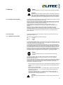
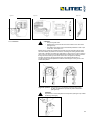
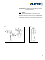
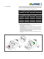
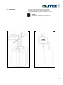
USER’S MANUAL
Electric chain hoists LH 250/500/1000/2000/2500
BVG-D8
BVG-D8+
BVG-C1
Highest Quality
Lifting Technology
Vers.03 – Released on 11.06.2014
1
Table of contents
0
General information ............................................................................ 4
0.1
0.1.1
0.2
0.2.1
0.3
0.4
0.4.1
0.4.2
0.5
0.5.1
0.5.2
0.5.3
0.6
0.6.1
General safety information ............................................................................................ 4
Safety and hazard precautions ...................................................................................... 4
General safety specifications and procedures ............................................................... 4
Warning paint / Marking / Danger signs ......................................................................... 4
Special safety directions ................................................................................................ 4
Notes on hazard protection ........................................................................................... 5
Hazards caused by mechanical influences .................................................................... 5
Hazards caused by electrical energy / power supply ..................................................... 5
Technical status ............................................................................................................. 6
Technical data ............................................................................................................... 6
Recurrent checks .......................................................................................................... 6
Warranty........................................................................................................................ 7
Operational parameters ................................................................................................. 7
Directions for using the instruction manual .................................................................... 7
1
Description .......................................................................................... 8
1.1
1.2
Operating conditions ..................................................................................................... 8
General description ....................................................................................................... 9
2
Start-up .............................................................................................. 11
2.1
2.2
2.2.1
2.2.2
2.2.3
2.2.4
Transport and assembly ...............................................................................................11
Connection ...................................................................................................................11
Electrical connection ....................................................................................................11
Load chain .................................................................................................................. 12
Limit switch ................................................................................................................. 14
Chain bucket ............................................................................................................... 15
3
Service and maintenance................................................................. 15
3.1
3.2
3.2.1
3.2.2
3.2.3
3.2.4
3.2.5
3.2.6
3.2.7
3.2.8
3.3
General regulations for service and maintenance work................................................ 15
Service and maintenance ............................................................................................ 16
Maintenance overview ................................................................................................. 16
Service overview ......................................................................................................... 16
Brake system .............................................................................................................. 16
Load chain .................................................................................................................. 17
Limit stop assembly ..................................................................................................... 17
Gearbox ...................................................................................................................... 17
Slip clutch.................................................................................................................... 17
Suspension parts......................................................................................................... 18
Ordering spare parts ................................................................................................... 18
4
Measures for obtaining a safe period of operation ....................... 18
4.1
4.2
Determining the actual utilization period S ................................................................... 18
General overhaul ......................................................................................................... 18
5
Appendix............................................................................................ 19
5.1
5.2
5.3
Technical data ............................................................................................................. 19
EC Declaration of conformity ....................................................................................... 21
EC Declaration of incorporation ................................................................................... 22
2
Spare parts / Ordering spare
parts
The correct order numbers for original spare parts can be obtained from the relevant spare
parts list. Please ensure that you have the following data on your chain hoist to hand. This will
enable the correct spare parts to be supplied without delay.
Electric chain hoist type
: ................................................................................................................
Manufacture number
: ................................................................................................................
Year of manufacture
: ................................................................................................................
Load capacity
: ................................................................................................................
Original spare parts for the electric chain hoist can be acquired from the following address:
Manufacturer
LITEC Italia spa
Via Martin Luther King, 70
31032 Casale sul Sile (TV), Italy
Tel. +39 0422.997300
Fax +39 0422.997399
[email protected]
www.litectruss.com
3
0 General information
The following symbols and terms are used in this instruction manual for safety and hazard
instructions:
0.1 General safety
information
DANGER !
Non-compliance, either in part or full, with operating instructions marked with this
symbol can result in serious personal injury or even death.
Danger notices must be strictly complied with.
0.1.1 Safety and hazard
precautions
CAUTION !
Non-compliance, either in part or full, with operating instructions marked with this
symbol can result in major damage to machinery, property or material.
Cautionary notices must be strictly adhered to.
NOTE
Following the instructions marked by this symbol will lead to more effective and
straightforward operation.
"Note" directions make work easier.
The instruction manual for the electric chain hoist must always be available within the operating
area of the hoist. The instructions mentioned in this manual must be strictly adhered to.
Furthermore, supplementary to the instruction manual, the statutory regulations governing
general accident prevention and environmental protection are to be enforced.
Operating and service personnel must have read and understood the operating instructions, in
particular the safety instructions, before commencing work. Protective equipment must be made
available for operating and service personnel and worn at all times.
The operator or his representative is responsible for supervising operating personnel and
ensuring they are aware of the hazards and safety implications of working with the electric hoist.
0.2 General safety
specifications and
procedures
− ............................................... Lubricate chain figure 0-1
− ............................................... CE symbol
figure 0-2
− ............................................... Model plate
figure 0-3
− ............................................... Data plate
figure 0-4
− ............................................... Voltage figure 0-5
0.2.1 Warning paint / Marking /
Danger signs
Figure 0-1
Figure 0-2
0.3 Special safety directions
Figure 0-3
Figure 0-4
Figure 0-5
Transport and assembly:
− Electric chain hoists, single parts and large components should be carefully affixed
to suitable and technically acceptable hoisting apparatus / load lifting members
−
Connection:
− Connection work is only to be performed by personnel specifically designated and
trained for the job
−
Start-up / operation:
− Before initial start-up, as well as daily start-up, carry out a visual check and carry
out the predefined user-checks routine
− Only operate the electric chain hoist if the protective and safety equipment provided
is ready and working
− Damage to the electric chain hoist and changes in its operational characteristics
must be reported immediately to the person responsible
− After use, or when in a non-operational mode, the chain hoist should be secured
against unauthorised and unintentional use
− Refrain from hazardous procedures
− See also operational parameters (chapter 0.6)
4
Cleaning / service / repair / maintenance / refitting:
− Use the working platforms and ladders provided for assembly work above body
height
− Do not use machine parts for this purpose
− Check electrical cables for damage or wear
− Ensure any oils or other agents used are discharged, collected and disposed of
safely and in an environmentally sound manner
− Reassemble and check safety apparatus that has been disassembled for servicing
or repairing the hoist once service and repair work has been completed
− Adhere to predefined testing and service intervals specified in the instruction
manual
− Follow the directions in the instruction manual regarding exchanging parts
− Operating personnel should be informed before commencing special or refitting
work
− Secure the repair working area
− Prevent the electric chain hoist from being inadvertently switched on during service
or repair work
− Erect warning signs
− Disconnect the power cable and ensure it cannot be inadvertently switched on
again
− Retighten screw connections that have been loosened for repair or service work
− Replace parts that are not reusable, such as O-rings, gaskets, self-locking nuts,
split-pins and washers
−
Shut down / storage:
− Clean and preserve (lubricate/grease) the chain hoist before long periods of
inactivity or storage
Hazardous areas must be clearly marked by warning signs and cordoned off. It must be
ensured that warnings regarding hazardous areas are given due attention.
0.4 Notes on hazard protection
0.4.1 Hazards caused by mechanical
influences
Hazards can stem from:
− incorrect application
− not following safety directions properly
− not carrying out test and service work thoroughly
Physical injury:
DANGER !
Unconsciousness and injury through:
− crushing, shearing, cutting and twisting
− drawing in, ramming, piercing and rubbing
− slipping, stumbling and falling
Causes:
− crush, shear and twist area
− parts rupturing or bursting
Safety options:
− keep floor, equipment and machinery clean
− eliminate leakages
− observe the required safety distance
0.4.2 Hazards caused by electrical
energy / power supply
Work on electrical apparatus or machinery may only be performed by qualified
electricians or persons under the supervision and guidance of qualified electricians,
in accordance with predefined electro-technical regulations.
Physical injury:
DANGER !
Death from electrical shock, injury and burns through:
− contact
− faulty insulation
− faulty servicing or repair work
− short circuit
5
Causes:
− contact with, touching or standing too close to uninsulated power and voltage
supply terminals
− use of uninsulated tools
− exposed electricity supply terminals following insulation failure
− inadequate safety checks following repair work
− incorrect fusing
Safety options:
− isolate machinery and equipment designated for repair or service work before
commencing such work
− first check isolated parts for voltage
− regularly check electrical fittings
− replace loose or damaged cables immediately
− always replace blown fuses with fuses of the correct value
− avoid contact with or touching live terminals
− only use insulated tools
0.5 Technical status
The present document was written in 2012. It corresponds to directive 2006/42/EC of
the European Parliament and of the Council of 17 May 2006.
0.5.1 Technical data
Models D8
Models D8 Plus
Models C1
table 0-8, page 4
table 0-9, page 5
table 0-10, page 6
The LITEC hoist models are designed with a shock factor of 1.40 in operation, in
accordance with DIN EN 818-7.Incidents investigated by the Employers Liability
Insurance Association generate lower shock factors than those occurring in normal
operation.
0.5.2 Recurrent checks
Each device/ unit operator should adequately note all checks, maintenance and
inspections performed in the log book, and have these confirmed by the competent
person in charge.
Incorrect or missing entries will lead to forfeiture of the manufacturer's warranty.
CAUTION !
Equipment and cranes should be periodically tested by an expert. Basically,
visual and functional checks should be performed to determine the
condition of components as regards damage, wear, corrosion or other
modifications. In addition, safety equipment is assessed for completeness
and efficiency. It may be necessary to dismantle the equipment under
inspection to correctly assess expendable parts.
CAUTION !
Suspension apparatus must be inspected over its entire length, including
covered or hidden parts.
CAUTION !
All periodical inspections should be arranged by the operator.
6
0.5.3 Warranty
− the warranty is void if the installation, operation, testing or maintenance is not
carried out according to these instructions
− troubleshooting and repair under warranty may only be carried out by qualified
persons and only after consultation and agreement with the manufacturer / supplier.
Any modifications to the product or the use of non-original replacement parts will
void the warranty.
0.6 Operational parameters
Electric chain hoists of the series LH are hoists of differing load capacities. They can be
installed as stationary or mobile units. Electric chain hoists are manufactured in
accordance with the latest technical developments and recognised safety standards,
and are tested for safe operation by the manufacturer.
Electric chain hoists are approved by various international institutes such as BG and
others.
Electric chain hoists of the above series may only be used when in an acceptable
technical condition, in accordance with their operating parameters, by trained personnel
in a safe and responsible manner.
The operational parameters of the electric chain hoist also encompass compliance with
the pre-defined operating, service and maintenance requirements laid down by the
manufacturer.
The operational parameters do not include:
− exceeding the defined load capacity
− pulling the load diagonally
− heaving, pulling or dragging the load
− standing under suspended loads (see di)
− transporting excessive loads
− pulling on the control cable
− failing to observe the load hook constantly
− running the chain over edges
− failing to observe the load constantly
− allowing the load to fall due to a slack chain
− use at temperatures below -10° C or above +40° C
− use in an explosive environment
See also table 0.6 for:
− transporting persons
− transporting loads when personnel are underneath
The LH series of electric chain hoists are intended for use in setting up events.
Events include such items as concerts, shows, conferences, meetings, exhibitions,
presentations, demonstrations, film or television shoots and similar. The location of such
events include, amongst other places, theatres, multipurpose halls, studios, film sets,
television and radio broadcasting, concert halls, conference centres, schools,
exhibitions, fairs, museums, discotheques, vaudeville, recreational parks, sports
facilities, open air theatres and meetings.
This standard differentiates between three types of electric chain hoists:
D8 Hoist
Electric chain hoist according to BGV D8/GUV-V D8 (previously GUV 4.2) "Winches,
lifting and pulling devices" for use as a chain hoist for lifting loads in construction.
D8 Plus Hoist
Electric chain hoist based on BGV D8/GUV-V D8 (previously GUV 4.2) "Winches, lifting
and pulling devices" for use as a chain hoist for lifting loads in construction with the
special characteristic of being able to hold loads statically above personnel, without the
use of secondary safety devices.
C1 Hoist (scenery hoist)
Electric chain hoist according to BGV C1/ GUV-V C1 (previously GUV 6.15) "Staging
and production facilities for the entertainment industry" for holding and moving loads
above personnel.
The types of electric chain hoists specified above can be operated both individually and
in groups.
7
Electric chain hoists are offered in a multiplicity of designs and feature options, as well
as with different safety devices. This means that the choice of chain hoist is extremely
important. Here consideration must be given to risks arising from the nature of the
operational use and the specific operating conditions.
The choice of the type of electric chain hoist depends on the operating conditions:
D8 with
secondary
safety device
D8
D8 Plus
C1
Where personnel are under the load
Erection / dismantling,
rigging operations
Holding loads
Scene movement
not
permitted
not
permitted
not
permitted
not
permitted
not
permitted
permitted
permitted
permitted
permitted
not
permitted
not
permitted
permitted
Where equipment is permanently installed in locations where events take place, electric
chain hoists according to BGV C1/GUV-V C1 should be provided, on account of the
mode of operation and the anticipated risks.
Inching operations, ground mooring and driving against the limit switches should be
avoided. The manufacturer accepts no responsibility for damage to equipment and third
parties ensuing from such action.
0.6.1 Directions for using the
instruction manual
This instruction manual includes the following chapters:
0
1
2
3
General information
Description
Start-up
Service and maintenance
4
5
Measures for obtaining a safe
period of operation
Appendix
Supplementary to the instruction manual, the following documentation from the operator
must be noted:
−
Declaration of conformity
−
Log book
−
Spare parts list(s)
−
Circuit diagrams
Page and figure numeration:
The pages are consecutively numbered. Blank pages are not numbered, however are
calculated together with the consecutive pages.
Figures are numbered consecutively by chapter.
8
1 Description
The ambient temperature must be between -10° C and +40° C.
When the equipment is commissioned, and periodically thereafter, the functionality of
both brakes must be examined. The periodic examination should be carried out by
competent personnel annually and by an expert every four years.
The verifiability of the individual brakes is to be provided by a control engineer. A sample
control scheme for a D8 Plus hoist or a sample guide for the PLC used in a C1 hoist can
be obtained from LITEC Italia spa.
1.1 Operating conditions
Classification according to application requirements:
Electric chain hoists and travelling gears are classified according to the following
regulations into ISO Groups:
−
−
−
−
−
DIN EN 14492-2
DIN 15400 (load hook)
FEM calculation regulations for series lifting equipment
(chain drive, motor, full load-life span)
ISO 4301-1: D (M3) = 400 h
Remarks about general revision (see chapter 4)
There is differing coefficient data for the ISO Groups that must be adhered to in
operation.
CAUTION !
The travelling gear is always classified as the same ISO Group as the
corresponding electric chain hoist.
NOTE
The ISO Group registration number of the electric chain hoist can be found
on the data plate.
The manufacturer will only guarantee the safety and lasting operation of the electric
chain hoist when used for applications that fall within its valid ISO Group coefficient
data.
Before the first start-up, the user must estimate according to the features in table 1-1,
which of the four types of load is applicable to the use of the electric chain hoist during
its whole service life. Table 1-2 shows standard values for the operating conditions of
the ISO Groups depending on the type of load and the time of operation.
CAUTION !
Before starting up the electric chain hoist for the first time, it must be
determined with which of the load types shown in table 1-1 the electric
chain hoist is to operate. Assignment to a load type or a load collective (k)
applies for the entire operational life of the equipment and may not be
altered for operational safety reasons.
Example 1: Ascertaining permissible running time of the electric chain hoist:
An electric chain hoist of the ISO Group M4 is to be used for medium stress load tasks
throughout its entire service life. This corresponds to load type <3 heavy> (see table
1-1). According to the values in table 1-2, the electric chain hoist should not be used for
longer than 0.5 - 1 hour per working day.
Example 2: Ascertaining permissible load type:
An electric chain hoist of the ISO Group M5 is to be used for approximately 6 hours per
working day, throughout its complete service life. Consequently the electric chain hoist
should be operated in accordance with the characteristics of the load type <1 light> (see
table 1-1).
9
Load type 2
medium
0.50 < k < 0.63
k = 0.63
Load type 3
heavy
0.63 < k < 0.80
k = 0.80
Load type 4
very heavy
0.80 < k < 1.00
k = 1.00
% of bearing capacity
% of bearing capacity
% of bearing capacity
Table 1-2 Operating conditions
Load type 1
light
k < 0.50
k = 0.50
% of bearing capacity
Table 1-1 Load collectives
% of running time
Full load by way of an
exception, however,
predominantly
low loads
% of running time
Frequently fully loaded,
however continuously
lightly loaded
% of running time
Frequently fully loaded,
continuous average
loading
% of running time
Regularly fully loaded
ISO Group according
to ISO 4301-1
Load collective
M3
M4
M5
M6
M7
Average running time per working day [h]
1 - light
k < 0.50
up to
2
2-4
4-8
8 - 16
over
16
2 - medium
0.50 < k < 0.63
up to
1
1-2
2-4
4-8
8 - 16
3 - heavy
0.63 < k < 0.80
up to
0.5
0.5 1
1-2
2-4
4-8
4 - very heavy
0.80 < k < 1.00
up to
0.25
up to
0.5
0.5 1
1-2
2-4
k = Load collective (type of load)
1.2 General description
Figure 1-1
1 Housing
2 Motor and brake
3 Rotor shaft with integrated slip clutch
4 Limit switch
5 Electrical controller
6 Chain drive
7 Gearbox
The electric chain hoist meets the requirements of the EC Machinery Directive and the
relevant EN and FEM standards. Housing and cover are made of a sturdy aluminum die
casting. Fins on the motor ensure optimum cooling. The chain box can be attached to
the compactly constructed housing. A drilled hole is provided for both the power supply
cable gland and the control cable. The lugs, or optionally the suspension hooks, are
attached to the flange ring.
GIS electric chain hoists are driven by asynchronous motors. For two-speed models a
pole switching version of the motor is fitted.
The braking system consists of a DC-operated spring loaded brake. When there is no
current, the pressure spring generates the braking torque.
For functional reasons, the slip clutch is installed in front of the brake system and
integrated into the rotor shaft. It protects the hoist from overload and takes on the
function of an emergency end stop for the highest and lowest hook positions.
A gear-type limit switch is fitted to limit the highest and lowest hook position. As an
option, emergency stop contacts with positive separation can be retrofitted downstream.
Electric chain hoists are fitted with a 42 V contactor control as standard. The emergency
stop contactor that is usually installed separates all three mains power phases when the
red button is pressed.
The high-strength round steel chain meets the requirements of grade DAT (8SS) to DIN
EN 818-7. Sprocket and pulley are hardened. The load hook, which complies with DIN
15400, is fitted with a safety latch. The two-or three-stage, closed spur gear units are
usually helically cut. The gears are mounted on roller bearings and run greased.
The standard equipment fitted to the electric chain hoist includes a control switch (up/
down with emergency stop).
10
DANGER !
Mechanical adjustments may only be performed by authorised specialists.
2 Start-up
CAUTION !
Operating staff must carefully read the operating instructions of the electric
chain hoists before its initial operation and carry out all checks. Only when
safe operation has been established may the device be put into operation.
Unauthorised persons may not operate the device or carry out work with it.
2.1 Transport and assembly
The safety directions for handling with loads should be followed (see chapter 0.3) when
transporting and assembling the electric chain hoist.
Electric chain hoists must be assembled by qualified staff, always bearing in mind the
accident prevention directions in chapter 0.2. Before assembly the electric chain hoist
must be stored in an enclosed room or covered area.
Should the electric chain hoist be destined for operation outdoors, then it is
recommended that a protection cover is erected to shield it from the effects of the
weather.
Wherever possible, the electric chain hoist should be transported in its original
packaging. The goods delivered should be checked for completeness and the
packaging disposed of in an environmentally sound manner. It is recommended that the
electric chain hoist is assembled and connected on-site by our qualified customer
service personnel.
2.2 Connection
Check the identification plate as to whether the chain hoist corresponds to the type
ordered (D8, D8 Plus, C1).
2.2.1 Electrical connection
The chain hoist must display the following markings:
D8…………..: Triangle
D8 Plus…….: Square
C1…………..: Circle
The appropriate electrical diagram can be found in the cover of the electric chain hoist.
In the case of the D8 Plus and C1 chain hoists, once the device is in position the power
must be disconnected using a lockable switch.
To commission the mechanically tested chain hoist as a C1 hoist, the control system
and the electrical assessment of the load measuring device must likewise be approved
by a certified inspection body as a C1 system (in accordance with BGV C1/GUV-V C1).
The principles laid out in BGG 912/GUV G 912 are to be used. An inspection and test
log book is to be set up, consisting of the equipment documentation provided by the
manufacturer and the test reports. Plans and descriptions of the electrical system are to
be supplemented by the appropriate control engineer on a project-specific basis.
DANGER !
Electro-technical adjustments may only be performed by authorised
specialists.
The mains connection cable, the mains connection fuse and the main switch for
connecting the electric chain hoist to the mains power supply must be installed
beforehand by the customer.
A 4-wire cable with a PE protective conductor is needed to provide the power supply for
three-phase models. A 3-wire cable with a protective conductor is adequate for singlephase models. The length and cross-section must be appropriate for the power
consumption of the electric chain hoist.
− Before connecting the electric chain hoist, check whether the operating voltage and
−
−
−
−
frequency that are specified on the name plate correspond to the available power
supply
Remove cover on electrical side
Insert connecting cable with M25 x 1.5 screwed cable connection into hole at side
and connect to terminals L1, L2, L3 and PE in accordance with supplied circuit
diagram (see figure 2-1)
Insert control cable with M20 x 1.5 screwed cable connection through hole in
underside of housing and connect to terminals 1, 2, 3, 4 and 10 (see figure 2-2)
Attach strain relief to housing (see figure 2-3)
CAUTION !
The control switch must be attached to the strain relief cord and not to the
cable.
11
Figure 2-1
Figure 2-2
Figure 2-3
Not Aus
2.2.2 Load chain
CAUTION !
− Only use original chains
− Welded seam of the chain links must face inward on the chain wheel
(see figure 2-5)
− The gearbox limit switch must be mechanically disabled in order to pull
in the chain, see chapter 2.2.3
2.2.2. Load chain
Before start-up and during operation the load chain must be oiled along its full length.
Oil must constantly be present on the internal, contacting and rubbing surfaces of the
chain links. Lubrication is carried out by submersion or with an oil can, using a creeping
gear oil. The end of the chain should be attached to a flexible piece of wire (1) and fed
through the chain wheel (2) of the electric chain hoist. Through short switching
impulses, the chain (3) will be housed correctly in accordance with figure 2-5.
The lifting height must be adjusted such that the hook fittings lie on the ground in the
lowest hook position.
Figure 2-5
Single fall operation: The load hook (1) is connected to the chain using a shim
(2). Bolt (3) installation is important for power transmission
(see figure 2-6).
CAUTION !
Pay attention to correct arrangement of suspension (see figure 2-7)! Grease
the bearings thoroughly.
Figure 2-6
12
Double fall operation: Connect load side of chain end to chain retainer (3) and fix in
housing guide rail. Assemble bottom sheave (1) with load hook
(2) in accordance with figure 2-9.
CAUTION !
Pay attention to correct arrangement of suspension (see figure 2-10)!
Do not twist chain lengthwise (see figure 2-8)! Grease the bearings
thoroughly.
Chain end: The chain end must be attached to the housing in accordance with figure 211.
The section of chain after the end stop (1) must be adjusted to the height of the chain
bucket. The length of the section of chain must be selected so that the end stop lies on
the floor of the magazine when the chain runs into it (see figure 2-11).
Figure 2-9
Figure 2-11
13
2.2.3 Limit switch
The electric chain hoist is equipped with a gearbox limit switch as standard. This is also
suitable for normal limit switch operation with a high degree of accuracy. The operation
of the limit switches (highest and lowest hook position) must be checked during start-up.
Three different transmissions are available that are adapted to the lift:
GCH 250/500
Transmission
i = 1:1
i = 1:3
i = 1:6
Colour
black
yellow
blue
Single fall lift [m]
20
60
120
Double fall lift [m]
10
30
60
GCH 1000
Transmission
i = 1:1
i = 1:3
i = 1:6
Colour
black
yellow
blue
Single fall lift [m]
30
80
180
Double fall lift [m]
15
40
90
GCH 1600/2000/2500
Transmission
i = 1:1
i = 1:3
i = 1:6
Colour
black
yellow
blue
Single fall lift [m]
36
110
220
Double fall lift [m]
18
55
110
Description of settings (see figure 2-12):
− Before pulling in the chain or changing the chain, the gearbox limit switch must be
mechanically disabled by securing the rocker (1)
− Pull in the chain
− Move to highest hook position, rotate red ratchet wheel (front) (2) to switching cam
of top limit switch (3); (rotate clockwise for higher hook position and anticlockwise
for lower hook position)
− Activate rocker, move to lowest hook position, rotate green switching wheel (rear)
(4) to switching cam of bottom limit switch (5); (rotate anticlockwise for higher hook
position and clockwise for lower hook position)
− Activate rocker (must engage in switch wheel)
− Check operation of limit switch; the end stop and the hook fittings must not touch
the housing
Figure 2-12
14
2.2.4 Chain bucket
−
Move chain out at load side until limit switch is activated
−
Attach chain bucket and allow chain to run in (see figure 2-13)
− Attach free end of chain to housing (see chapter 2.2.2)
DANGER !
All steel plate chain buckets must be equipped with an additional wire cable
with a minimum diameter of 2 mm (see figure 2-14).
Figure 2-13
Figure 2-14
Figure 2-14
15
3 Service and maintenance
3.1 General regulations for service
and maintenance work
Operating failures in electric chain hoists affecting the safe operation of the device
should be remedied immediately.
CAUTION !
Maintenance and repair work on the electric chain hoist may only be carried
out by qualified and trained personnel.
CAUTION !
If the operator performs maintenance work on an electric chain hoist on his
own account, the type of maintenance performed together with the date
carried out must be entered in the log book.
Alterations to, as well as modifications and supplements to electric chain hoists which
may affect safety must be authorized by the manufacturer in advance. Structural
alterations to chain hoists not authorized by the manufacturer exempt the manufacturer
from liability in case of damage.
Material warranty claims will only be recognized if solely manufacturer’s genuine spare
parts have been used.
We explicitly wish to point out that those original parts and accessories not supplied on
our behalf cannot be inspected or released by us.
General:
Service and maintenance are preventive measures designed to preserve the full
functionality of electric chain hoists. Non-compliance with service and maintenance
routines can result in reduction in the useful function of and/ or damage to electric
chain hoists.
Service and maintenance work should be carried out at the predefined time intervals,
in accordance with the instruction manual (table 3-1 and 3-2).
During service and maintenance work, general accident prevention directions, special
safety directions (chapter 0.3) as well as hazard protection instructions (chapter 0.4)
should be followed.
DANGER !
Service and maintenance work should only be performed on unloaded
electric chain hoists. The main switch must be off. The lower sheave or
hook fittings must be lying on the floor or a maintenance platform.
Maintenance work encompasses visual checks and cleaning routines. Service work
includes additional functional checks. During the functional checks, all securing
elements and cable clamps must be checked for secure seating.
Cables must be inspected for dirt, discoloration and arc spots.
CAUTION !
Used operating materials (oil, lubricants, etc.) should be safely collected
and disposed of in an environmentally friendly manner.
Service and maintenance intervals are defined as follows:
t
: ..... daily
3M
: quarterly
12 M
: annually
The predefined service and maintenance intervals should be reduced when the loading
of the electric chain hoist is exceptionally large and when frequently operated in adverse
conditions (dust, heat, humidity, steam, etc.).
16
3.2 Service and maintenance
3.2.1 Maintenance overview
See table 3-1.
Table 3-1 Maintenance overview
Term
t
Activity
Notes
1. Load chain
X
visual check
clean and lubricate as needed
see chapter 2.2.2
2. Hoist and carriage
X
abnormal noise check
seal check
3. Power supply cable
X
visual check
4. Limit switch
X
5. Seal
3M
12 M
function check
X
6. Cable discharging device control cable
see chapter 2.2.3
visual check
X
visual check
3.2.2 Service overview
See table 3-2.
Table 3-2 Service overview
Term
t
1. Load chain
3M
12 M
Activity
Notes
see chapter 2.2.2 / 3.2.4
X
lubricate
measure wear
see chapter 3.2.3
X
2. Brake system
X
function check with load
3. Electrical fittings
X
X
function check
4. Securing screws on suspended parts
and load hook with accessories
X
check for cracks
check screw movement
see chapter 3.2.8
5. Gearing
X
visual check wear
see chapter 3.2.6
6. Limit switch
X
check switching elements
see chapter 2.2.3
7. Slip clutch
X
function check
see chapter 3.2.7
The spring-loaded brake is a solenoid operated single disk brake with two friction
surfaces. The braking force is applied by compression springs. The braking torque is
generated when no current is applied. The ventilation is electromagnetic. The brake
operates with DC current.
The brake must be able to hold the nominal load in power free mode without any
problems.
3.2.3 Brake system
CAUTION !
The brake coil voltage must be the same as the operating voltage.
NOTE
The brake has no air gap adjustment. If the air gap (a max., table 3-3 and
figure 3-1) reaches maximal value, the brake pad needs changing.
Table 3-3 Air gap
Figure 3-1
GCH 250/500
GCH 1000
GCH 1600/2000/2500
Air gap (a)
[mm]
+0.15
0.4 0
+0.2
0.5 0
+0.2
0.5 0
Air gap (a max.)
[mm]
0.7
0.9
0.9
Torque value
[Nm]
3
10
10
17
3.2.4 Load chain
The load chain should be periodically checked for abrasion. The check is based upon
three measurements: see accepted wear factors (table 3-4) and measurement points
(figure 3-2).
CAUTION !
The chain should be replaced when the measurements exceed or fall short
of those defined in the table. The chain wheel and chain guide should be
checked for wear at the same time and, where necessary, be replaced.
Only use original chains. The chain links should not be welded.
The new chain is installed in accordance with chapter 2.2.2.
NOTE
For ease of installation, the old chain and new chain can be connected by a
piece of flexible wire.
Table 3-4 Wear factors load chain
Figure 3-2
GCH 250
GCH 500
GCH 1000
GCH 1600
GCH 2000/2500
Chain type d x t
[mm]
4 x 12.3
5 x 15.3
7 x 22
9 x 27
10 x 28
Tolerances in accordance with: DIN 685, part 5
DIN EN 818-7
1. Measurement over 11 chain links; a = 11t
[mm]
138.0
171.6
246.8
302.9
314.2
2. Measurement over 1 chain link 1t
[mm]
12.9
16.0
23.1
28.35
29.4
[mm]
3.6
4.5
6.3
8.1
9.0
3. Measurement of the chain link diameter
d1 + d2
dm =
2
; (dm min. = 0.9 x d)
3.2.5 Limit stop assembly
CAUTION !
A damaged buffer plate, underneath the housing, must be replaced.
Screw connections at the limit stop and shims or lower sheaves should be checked and,
where necessary, tightened to the right torque. For coefficient data see chapter 3.2.8.
3.2.6 Gearbox
The gearing has continual lubrication.
Lubricant ....................... : Strub N1424
Can be mixed and is compatible with all other similar brand
name grease (DIN 51502: GP OM-20)
Lubricant quantity .......... : GCH 250/500 ................. : 0.4 kg
GCH 1000...................... : 1.0 kg
GCH 1600/2000/2500 .... : 1.8 kg
3.2.7 Slip clutch
The slip clutch is set at 125% at the factory and can be relied on to prevent the chain
hoist from being overloaded (the force limiting factor according to DIN EN 14492-2 is
ΦDAL = 1.4). The coating is wear resistant.
CAUTION !
Adjustment and testing of the slip clutch may only be carried out by
authorized personnel and must be recorded in the log book.
18
All statically loaded parts are considered suspension parts. The bearing surfaces of the
slewing suspension parts must be periodically greased.
Torque values for screws of property class 8.8 according to DIN ISO 898:
3.2.8 Suspension parts
M5
6 Nm
M6
10 Nm
M8
24 Nm
M 10
48 Nm
M 12
83 Nm
3.3 Ordering spare parts
Information on how to order spare parts can be found on page 3.
The appropriate assembly diagram is considered to be a supplement to the parts
catalogue.
4 Measures for obtaining a
safe period of operation
The statutory and health requirements of the EU regulations stipulate that specific
dangers which may arise from fatigue or ageing must be prevented.
Accordingly, operators of standard hoist gear are obliged to determine the actual
utilization. The actual utilization period is determined and recorded as part of the annual
inspection by customer service engineers. A general overhaul must be carried out when
the theoretical utilization limit is reached, or after no more than 10 years.
All checking and the general overhaul itself must be arranged by the operator of the
hoist gear. The following theoretical utilization periods apply to electric chain hoists that
are categorized according to ISO 4301-1 (converted into full-load hours):
M3
400 h
M4
800 h
M5
1600 h
M6
3200 h
M7
6300 h
The actual utilization period depends on the daily operating time and the load collective.
Running time is determined from information provided by the operator or recorded using
a meter that counts the number of operating hours. The load collective is determined in
accordance with table 1-1, page 9. These two items of information are used to calculate
the annual utilization period from table 4-1.
If an operating data acquisition system (BDE) is used, the actual utilization can be read
out directly by our experts during the annual inspection.
4.1 Determining the actual
utilization period S
CAUTION !
The values periodically calculated or read-off must be recorded in the log
book.
On reaching the theoretical service life (no later than 10 years for recording without
BDE), a general overhaul should be performed. This enables the equipment to continue
operating safely for a further period of utilization (service life). Components must be
inspected and/ or replaced in this overhaul according to table 4-2. Inspection and
approval for further use must be performed either by a specialist company authorized by
the manufacturer, or by the manufacturer personally.
The inspector determines: – the new theoretical utilization possible
– the maximum period until the next general overhaul
4.2 General overhaul
This data should be recorded in the log book.
Table 4-1 Annual service life
Utilization
per day [h]
Table 4-2 General overhaul
<= 0.25 <= 0.50
(0.16)
(0.32)
<= 1.0
(0.64)
Load
collective
<= 2.0
(1.28)
<= 4.0
(2.56)
<= 8.0
(5.12)
<= 16.0
(10.24)
> 16.0
(20.48)
Annual service life [h]
k = 0.50
6
12
24
48
96
192
384
768
k = 0.63
12
24
48
96
192
384
768
1536
k = 0.80
24
48
96
192
384
768
1536
3072
k = 1.00
48
96
192
384
768
1536
3072
6144
Components of GCH-models
all types
Brake
Motor shaft
Gear teeth
Antifriction bearing
Washers
Chain
Chain wheel, chain guide
Deflection wheels
Suspension
Load hook
Travelling gear, running wheel
Contactor, limit switch
* replace when worn
Check for wear *
Replace
x
x
x
x
x
x **
x
x
x
x
x
x
** replace no later than at general overhaul
19
5 Appendix
Table 0-8
D8 technical data
Term
Dead
weight
M3 (1Bm)
150 s/h, 25% duty
1 fall
load
normal
hoist
250/1NL
D8
500/1NL
D8
1000/1NL
D8
2000/1NL
D8
2000/1NL
D8
Table 0-9
Term
LCH
1000/1NL
D8 Plus
LCH
2000/1NL
D8 Plus
Table 0-10
Term
1 fall
tot. load
climbing
hoist
M4 (1Am)
180 s/h, 30% duty
1 fall
load
normal
hoist
1 fall
all. load
climbing
hoist
1 fall
tot. load
climbing
hoist
Chain safety Chain safety
factor
factor use as
normal use climbing hoist
M5 (2m)
240 s/h, 40% duty
1 fall
load
normal
hoist
1 fall
all. load
climbing
hoist
1 fall
tot. load
climbing
hoist
Chain safety Chain safety
factor
factor use as
normal use climbing hoist
M6 (3m)
300 s/h, 50% duty
1 fall
load
normal
hoist
1 fall
all. load
climbing
hoist
1 fall
tot. load
climbing
hoist
Chain safety Chain safety
factor
factor use as
normal use climbing hoist
Lifting
speed
1 fall
[kg]
[kg]
[kg]
[kg]
[kg]
[kg]
[kg]
[kg]
[kg]
[kg]
[kg]
[kg]
[kg]
25
250
225
250
8.20
8.20
200
175
200
10.25
10.25
160
135
160
12.81
12.81
125
100
125
16.40
16.40
4
30
500
470
500
6.40
6.40
400
370
400
8.01
8.01
320
290
320
10.01
10.01
250
220
250
12.81
12.81
4
50
1000
950
1000
6.28
6.28
800
750
800
7.85
7.85
630
580
630
9.96
9.96
500
450
500
12.55
12.55
4
80
2000
1920
2000
6.40
6.40
1600
1520
1600
8.01
8.01
1250
1170
1250
10.25
10.25
1000
920
1000
12.81
12.81
4
80
2000
1920
2000
6.40
6.40
1600
1520
1600
8.01
8.01
1250
1170
1250
10.25
10.25
1000
920
1000
12.81
12.81
8
[m/min]
Chain
safety factor
normal use
Chain safety
factor use as
climbing hoist
Chain
safety factor
normal use
Chain safety
factor use as
climbing hoist
Lifting
speed
D8 technical data
Dead
weight
M3 (1Bm)
150 s/h, 25% duty
Chain
safety factor
normal use
1 fall
load
normal
hoist
1 fall
all. load
climbing
hoist
1 fall
tot. load
climbing
hoist
[kg]
[kg]
[kg]
[kg]
50
500
450
500
12.55
80
1000
920
1000
12.81
Chain safety
factor use as
climbing hoist
M4 (1Am)
180 s/h, 30% duty
Chain
safety factor
normal use
1 fall
load
normal
hoist
1 fall
all. load
climbing
hoist
1 fall
tot. load
climbing
hoist
[kg]
[kg]
[kg]
12.55
500
450
500
12.55
12.81
1000
920
1000
12.81
Chain safety
factor use as
climbing hoist
M5 (2m)
240 s/h, 40% duty
1 fall
load
normal
hoist
1 fall
all. load
climbing
hoist
1 fall
tot. load
climbing
hoist
[kg]
[kg]
[kg]
12.55
500
450
500
12.55
12.81
1000
920
1000
12.81
M6 (3m)
300 s/h, 50% duty
1 fall
1 fall
load
normal
hoist
1 fall
all. load
climbing
hoist
1 fall
tot. load
climbing
hoist
[kg]
[kg]
[kg]
12.55
500
450
500
12.55
12.55
4
12.81
1000
920
1000
12.81
12.81
4
[m/min]
D8 technical data
Dead
weight
M3 (1Bm)
150 s/h, 25% duty
1 fall
load
normal
hoist
500/1NL
C1
1000/1NL
C1
2000/1NL
C1
1 fall
all. load
climbing
hoist
Chain safety Chain safety
factor
factor use as
normal use climbing hoist
1 fall
all. load
climbing
hoist
1 fall
tot. load
climbing
hoist
Chain
Chain safety
safety factor factor use as
normal use climbing hoist
M4 (1Am)
180 s/h, 30% duty
1 fall
load
normal
hoist
1 fall
all. load
climbing
hoist
1 fall
tot. load
climbing
hoist
[kg]
[kg]
220
250
12.81
12.81
[kg]
[kg]
[kg]
30
250
220
250
50
500
450
500
12.55
12.55
500
450
500
12.55
80
1000
920
1000
12.81
12.81
1000
920
1000
12.81
12.81
[kg]
Chain safety
factor use as
climbing hoist
[kg]
12.81
250
Chain
safety factor
normal use
M5 (2m)
240 s/h, 40% duty
1 fall
load
normal
hoist
1 fall
all. load
climbing
hoist
1 fall
tot. load
climbing
hoist
Chain
safety factor
normal use
Chain safety
factor use as
climbing hoist
[kg]
[kg]
[kg]
250
220
250
12.81
12.81
12.55
500
450
500
12.55
12.81
1000
920
1000
12.81
M6 (3m)
300 s/h, 50% duty
1 fall
load
normal
hoist
1 fall
all. load
climbing
hoist
1 fall
tot. load
climbing
hoist
Chain
safety factor
normal use
Chain safety
factor use as
climbing hoist
Lifting
speed
1 fall
[kg]
[kg]
[kg]
250
220
250
12.81
12.81
[m/min]
4
12.55
500
450
500
12.55
12.55
4
12.81
1000
920
1000
12.81
12.81
4
20
EC DECLARATION OF CONFORMITY
Declaration for machinery according to EU directives 2006/42/EC, Annex II A, 2004/108/EC, Annex I and 2006/95/EC, Annex III
We,
GIS AG, Hebe- und Fördertechnik, Luzernerstrasse 50, CH-6247 Schötz
hereby declare that the following machinery
GIS electric chain hoist, series
payload range
GCH
100 kg - 5000 kg
developed for lifting and lowering loads, is, in standard production and from the 2005 model year, inclusive of
load control, meets the essential requirements of the following EC directives, as applicable to the scope of the
delivery:
EC Machinery Directive
EC Directive on Electromagnetic Compatibility
EC Low Voltage Directive
2006/42/EC
2004/108/EC
2006/95/EC
Harmonized standards applied:
ISO 2374
DIN EN 818-7
DIN EN ISO 13849-1
DIN EN 14492-2
DIN EN 60204-32
Lifting appliances; Range of maximum capacities for basic models
Short link chain for lifting purposes; Part 7: Grade T
Safety-related parts of control systems; Part 1: General principles for design
Cranes, power driven winches and hoists; Part 2: Power driven hoists
Electrical equipment of machines; Part 32: Requirements for hoisting machines
Standards and technical specifications applied:
FEM 9.751
FEM 9.755
DIN 56950
VPLT.SR2.0
Power driven series hoist mechanisms; Safety
Measure for achieving safe working periods
Entertainment technology
Standards to the entertainment technology
Authorized to compile relevant technical documentation:
Mr. Pius Engel, GIS AG, Luzernerstrasse 50, CH-6247 Schötz.
Schötz, 08.11.2012
I. Muri
Director
GIS AG
E. Widmer
Sales Manager
Responsible for completion, installation and commissioning as per instructions:
Place: ………………………………………
Date: ......................................................................................................
Responsible: ..............................................................................................................................................................
Company: ..................................................................................................................................................................
21
EC DECLARATION OF INCORPORATION
Declaration for the incorporation of partly completed machinery according to EU directives 2006/42/EC, Annex II B, 2004/108/EC, Annex I
and 2006/95/EC, Annex III
We,
GIS AG, Hebe- und Fördertechnik, Luzernerstrasse 50, CH-6247 Schötz
hereby declare that the following partly completed machinery
GIS electric chain hoist, series
payload range
GCH
100 kg - 5000 kg
developed for lifting and lowering loads, is, in standard production and from the 2005 model year, inclusive of
load control, intended for installation in machinery and meets the essential requirements of the following EC
directives, as applicable to the scope of the delivery:
EC Machinery Directive
EC Directive on Electromagnetic Compatibility
EC Low Voltage Directive
2006/42/EC
2004/108/EC
2006/95/EC
We also declare that the technical documentation has been compiled in accordance with Annex VII, Part B of
Directive 2006/42/EC. We undertake to submit the specific documents relating to the lifting mechanism to
national authorities on receipt of a reasonable request. The information will be supplied by electronic means.
Harmonized standards applied:
ISO 2374
DIN EN 818-7
DIN EN ISO 13849-1
DIN EN 14492-2
DIN EN 60204-32
Lifting appliances; Range of maximum capacities for basic models
Short link chain for lifting purposes; Part 7: Grade T
Safety-related parts of control systems; Part 1: General principles for design
Cranes, power driven winches and hoists; Part 2: Power driven hoists
Electrical equipment of machines; Part 32: Requirements for hoisting machines
Standards and technical specifications applied:
FEM 9.751
FEM 9.755
DIN 56950
VPLT.SR2.0
Power driven series hoist mechanisms; Safety
Measure for achieving safe working periods
Entertainment technology
Standards to the entertainment technology
This declaration only refers to the lifting mechanism. Commissioning is prohibited until it has been
firmly ascertained that the crane, in which the lifting mechanism is installed, complies with the
provisions of the above EC directives.
Authorized to compile relevant technical documentation:
Mr. Pius Engel, GIS AG, Luzernerstrasse 50, CH-6247 Schötz.
Schötz, 08.11.2012
GIS AG
I. Muri
Director
E. Widmer
Sales Manager
Responsible for completion, installation and commissioning as per instructions:
Place: ……………………………………….
Date: ......................................................................................................
Responsible: ..............................................................................................................................................................
Company: ..................................................................................................................................................................
22