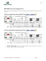
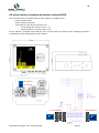
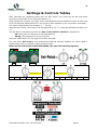
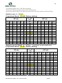
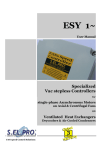
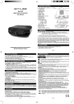
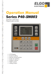
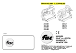
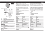
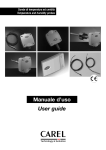
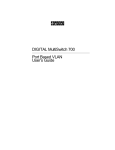
1
1 EC-nano UK user manual rev. 2.1 del 20.11.2012 selpro.it 2 ECN series selection codes The following table shows the rule for creating the ordering code and the admissible variants for each feature or function ZD ECN a bbb c d e a Phase supply 1 bbb Supply voltage 020 c Voltage type D Vdc d set-point number 1 SP1 (SP +SPadj.) e Inputs types f g h i Single phase 20 (-10%/+25%) D M T INPUT 1 INPUT 2 0..70°C 4-20mA 4-20mA 4-20mA 0..70°C 0..70°C f Protection box B S IP00 din rail g Not used 0 Not used h Reserved 0 Reserved for special customized version i Revision index 0 Last coded revision or personalization for the customer Code ZDECN1020D1DB000 ZDECN1020D1MB000 ZDECN1020D1TB000 ZDECN1020D1DS000 ZDECN1020D1TS000 ZDECN1020D1MS000 IP66 Description EC NANO 0-10V CONTROLLER 20VDC -10%/+25% 1 ING. 0/70°C NTC 1 ING. 4-20mA - IP00 DIN RAIL EC NANO 0-10V CONTROLLER 20VDC -10%/+25% 2 ING. 4-20mA - IP00 DIN RAIL EC NANO 0-10V CONTROLLER 20VDC -10%/+25% 2 ING. 0/70°C NTC - IP00 DIN RAIL EC NANO 0-10V CONTROLLER 20VDC -10%/+25% 1 ING. 0/70°C NTC 1 ING. 4-20mA - IP66 EC NANO 0-10V CONTROLLER 20VDC -10%/+25% 2 ING. 0/70°C NTC - IP66 EC NANO 0-10V CONTROLLER 20VDC -10%/+25% 2 ING. 4-20mA - IP66 EC-nano UK user manual rev. 2.1 del 20.11.2012 selpro.it 3 You must follow very carefully the safety prescription specified below, every time you interact with the device. Read carefully and follow the instructions in this manual; keep a copy with the device. Before starting the device, the user must determine it suitability for the use he/she intends to make of it, taking all risk and liabilities arising from improper use of the device. The installation, commissioning, and use of this device should only be performed by qualified personnel with knowledge of the product technical standards, in accordance with safety and personal protection standards. The device contains no user-serviceable parts: do not tamper with or disassemble the internal parts of the device. Doing so will void the warranty, and may cause serious injury to persons and property. The user must be protected from the power supply, and the motor must be equipped with protection against overvoltage, in accordance with the applicable standards. Do not power the device without the protective cover in place. Never touch any parts of the electrical circuit when power is on. Do not alter or damage the equipment identification tags. Allowed Use The device is aimed at regulating motorized actuators, through the 0-10Vdc control signal command; in particular the software is projected for the regulation of temperature or pressure of ventilated heat exchangers, by the control of the rotation speed of single and three-phase synchronous (EC) motors applied to axial and centrifugal fans used in air conditioning, refrigeration or air handling and treatment. Any use other than that allowed ones is prohibited. EC-nano UK user manual rev. 2.1 del 20.11.2012 selpro.it 4 INTRODUCTION This manual contains all the information necessary for the installation, operation, and maintenance of the EC‐nano device. Its smooth operation and duration depend on proper maintenance and attention during use. Do not proceed in any way to install or use of the product without first becoming familiar with the safety instructions contained in this manual. This manual is an integral part of the device and must accompany it throughout its entire life cycle, until demolition. In order to provide an effective consultation, the notes of particular significance are highlighted as follows: The notes marked with this symbol aim at ensuring maximum uptime for maximum machine performance. The notes marked with this symbol are particularly significant for safety purposes, and must be strictly adhered to by anyone working on the machine. Before and during installation, you must follow very carefully the safety prescription specified below. For the control of delicate products, or high value products that need to be kept within specific limits, we recommend installing a separate monitoring device, equipped with alarm contacts. The installation must be done by a qualified technician who carefully connects the electrical system, fixes the cables in their definitive position, and turns it on. Incorrect installation can cause serious injury to persons and serious damage property. As entries for the connection cables, you must use only the holes provided, in order to prevent infiltration of external agents (water, dust, etc.), and maintain the device IP65 protection by using the supplied cable gland and the quality sheaths and cables that properly fit. Reassemble and make sure the outer protective cover closes perfectly. EC-nano UK user manual rev. 2.1 del 20.11.2012 selpro.it 5 EC-NANO Controller The EC-nano device is a digital regulator, simple and practical, suitable for the management of motorized actuators with input from the remote control 0-10V. Embedded software is specialized for the dynamic management of ventilated heat exchangers. The controller can manage the temperature or pressure of work, working in either (PID algorithm IES: Intelligent Energy Saving) Proportional that, to maintain the desired value of pressure or temperature of the fluid in output. FRIENDLY Setting of the set point (SP+SPadj), allows rapid commissioning of the system The device supports two types of inputs: (1) signals from 4-20mA transducers; (2) signals from NTC probes It can therefore operate in: MASTER mode: the output 0(1)-10 voltage varies as a function of one or more signals, maintaining the prevalent input within a given proportional band; The device is designed to manage 2 inputs. In case more inputs are needed, one or more input expansion modules of the MEI-4 model (max 6) must be used, each of which allows to connect up to four signals in mA/NTC for each device. If you connect multiple inputs, you can select whether to use the greater or lesser in value. The system compares all incoming signals, and the regulation is performed by using the prevalent signal. The system is available in three (3) different versions: - DIN rail mounting (IP00) - For outdoor mounting (IP66) - In cabinet for outdoors mounting (IP65), complete with ON-OFF power-switch, three-phase protection against short circuits and direct connection from 1 to 9 SINGLE or three-phase EC fans. The features in place and selected via DIP-switch, complete the proposed control technology. EC-nano Available cabinet protection IP00 IP66 EC-nano UK user manual rev. 2.1 del 20.11.2012 IP65 selpro.it 6 Technical Characteristics: • Power supply 20Vdc (not insulated) -10/+25%, supplied directly by the EC motor or an external power supply; absorption of the electronic circuit: (max 18 mA), plus the transducer/s (4-20mA). • Available in: - IP00 (DIN rail) for electric cabinet - IP66 (110x110x58) for outdoor applications (-20T50) - IP65 (240x253x125) complete protection electric box. • Three (3) models are available, with two (2) inputs, with automatic selection of greater value, designed for the connection of: 1 temperature sensor NTC 10K @ 25 ° C + 1 pressure transducer 4-20mA (standard) 1 or 2 (4-20mA) pressure transducers ((attantion to the available mA on power supply), 1 or 2 temperature sensors (NTC 10K @ 25 ° C), to control the EC fans through the command 0(1)-10Vdc, for to maintain the controlled °C or Bar to the projected value (Set-Point). Standard functions: 2 inputs: 4-20mA or NTC 10K @ 25°C or mixed (1xNTC & 1x4-20mA=factory setting) 1 analog output 0-10Vdc short-circuit protected, for motorized actuators, specialized for the control of EC fans (MAX n. 30 with input impedance from 100kohm) or motorized actuators (valves, dampers, ...) - Led DL1 (RUN) flashing CPU runs at a frequency of 1Hz OK - Led DL2 (FAIL) for alarms: o No. 1 flash for input/s UNDER scale(sensor disconnected) o No. 2 flashes for input/s OVER scale (sensor short circuit) o No. 3 flashes for error in the input connection (ex. : in the standard configuration with NTC input for IN 1 and 4-20mA pressure transducer for IN2) N.B.: to reset the alarm condition no. 3, it is necessary to switch off the controller - - Led DL3 (-) flashing: input value below the set point Led DL4 (+) flashing: input value above the set point 2 switches 13 positions for the friendly setting of: o (SP) main Set-Point + (SP-Adj) Set-Point adjustment 4 Dip Swicht (SW1) for changing the default functionality: o PID or Proportional control (all parameters loaded in the factory) o Direct or Reverse regulation, o activation of surveillance control command (exit 1-10Vdc), to by pass the controller with the emergency speed (System "Cable break" function to be activated on the EC fan software) Factory STANDARD EC-nano UK user manual rev. 2.1 del 20.11.2012 selpro.it 7 Functionality: - PID (algorithm IES) or Proportional, for single or double input, with the automatic selection of the greater value / active channel Regulation of EC Motors or motorized actuators, through 0 (1)-10Vdc analog output, in MASTER mode (Proportional or PID), with 1 or 2 sensors, 4-20mA or NTC 10K @ 25°C - (*)You can select the Cable-Break function, that in case of failure of the control signal (control signal @0V) activates the emergency speed on EC fan (programmable with EC-Manager) 1234 OUT 0_10V P Modo DIRECT 1234 PTM OUT 0_10V P Modo REVERSE PTM 10.0 V 10.0 V (*) 1234 1.0 V 1.0 V Emergency zone 1234 Emergency zone 0.0 V IN SP SP PTF PTM DMF Db IN 1234 P P OUT IN SP P 1234 0.0 V Output command value 0(1)-10Vdc Selected/ on work Input signal value Set point value (SP +/-SP adj) Proportional Band (factory defult) MIN projected Pressure or Temperature: system conditions set the project value to achieve the compressors best Energy Saving MAX projected Pressure or Temperature: system conditions reached by power exchange at design conditions Difference of temperature or pressure (PTM-PTF); the displacement from PTF to PTM occurs by the increase of ambient temperature. Area of "Dead-Band" of SP: is +/-2.5% of P (Proportional Band). When activated, stabilizes the control if the value of IN is inside. PID 1234 PTF OUT 0_10V Modo Direct DMF 1234 PTM OUT PTM 0_10V PID Modo Reverse DMF PTF Db Db 10.0 V 10.0 V (*) 1234 1.0 V 1.0 V Emergency zone 0.0 V 1234 SP P EC-nano UK user manual rev. 2.1 del 20.11.2012 IN Emergency 1234 zone 0.0 V IN SP P selpro.it 1234 8 Transducer & Probe terminal block 1. 2. 3. 4. Transducer input N°1 (IN1) GND - Ground ( per NTC) Transducer supply +V (20Vdc) Transducer input N°2 (IN2) Power supply & output Command terminal block 1. 2. 3. 4. Ingresso tensione alimentazione da +20Vdc (min 50mA) da EC Motor Massa Alimentazione (solo con TS aux. esterno) Massa comando EC Motor Segnale 0-10V comando EC Motor Available Dip Swicth selections Dip 1 2 3 4 ON OFF Proportional regulation Mode “ Direct” Output 0-10V (standard) Free customizable The “Cable break” system, PID Regulation Mode “ REVERSE” Output 1-10V (Cable-break) Free customizable directly programmable with EC-Manager, 1234 automatically activates the EC fan Emergency speed. SP setting (Set-Point & Set adjust)) 1. SP 13 positions switch to set the working point 2. SP adj. 13 positions switch to set the adjustment working point 3. Led di visualizzazione: - DL1 external supply O.K. - DL2 for Alarms - DL3 & DL4 for differences between SP and working input Attention: when the two values (SP & IN) are matching, the LEDs are flashing together EC-nano UK user manual rev. 2.1 del 20.11.2012 selpro.it 9 The drawing below shows the available enclosure for the EC nano controller IP00 DIN rail The EC nano controller is available for DIN rail application IP66 cabinet The IP66 enclosure for the EC nano controller, is complete with rubber gland IP68 IP65 cabinet The IP65 electric board for EC nano controller, is completed by the cable glands kit EC-nano UK user manual rev. 2.1 del 20.11.2012 selpro.it 10 EC fans Connection: To connect single and three-phase EC fans: ebm-papst and Ziehl-Abegg, for the terminals connection refer to the following drawings. NB: with ebm-papst EC fan, check the maximum available current (mA) On single phase ebm-papst terminal block, are available: - KL1 : L/N for motor power supply - KL2 : contacts of fan warning/alarm relay - KL3 : o Output power supply +20V (min 50mA) o Input for 0-10Vdc from remote command On three phase ebm-papst terminal block, are available: - KL1 : L1/L2/L3 for motor power supply - KL2 : contacts of fan warning/alarm relay - KL3 : o Output power supply +20V (min 50mA) o Input for 0-10Vdc from remote command On single phase ziehl-abegg terminal block, are available: - L/N for motor power supply - contact of fan warning/alarm relay - Output power supply +20V (70mA for the supply of two transducers) - Input for 0-10Vdc from remote command On three phase ziehl-abegg terminal block, are available: - L1/L2/L3 for motor power supply - contact of fan warning/alarm relay - Output power supply +20V (70mA for the supply of two transducers) - Input for 0-10Vdc from remote command EC-nano UK user manual rev. 2.1 del 20.11.2012 selpro.it 11 EC-nano with ebm-papst EC fans Below are shown the connections of EC-nano controller with ebm-papst single and three phase EC fans EC-nano supplied by three-phase EC fan EC-nano supplied by single-phase EC fan - Remote Alarm signal: connect the relays contacts of each fan as shown; in case of failure you have a remote malfunction signal EC-nano UK user manual rev. 2.1 del 20.11.2012 selpro.it 12 EC-nano with ziehl-abegg EC fans Below are shown the connections of EC-nano controller with ziehl-abegg single and three phase EC fans EC-nano supplied by three-phase EC fan EC-nano supplied by single-phase EC fan - Remote Alarm signal: connect the relays contacts of each fan as shown; in case of failure you have a remote malfunction signal EC-nano UK user manual rev. 2.1 del 20.11.2012 selpro.it 13 EC-nano supplied by external For electric board application, the EC-nano is available for DIN rail application. In this case it’s possible to supply the controller with a transformer with 20V (-10/+25%) and 50mA min (70mA with 2 4-20mA transducers). The following is the example of the EC-nano, powered by external transformer, and connected with three-phase ebm-papst EC fans. EC-nano UK user manual rev. 2.1 del 20.11.2012 selpro.it 14 EC-nano supplied from the Expansion Inputs Command (MEI-4) In the case of applications with multiple pressure sensors in current (4-20mA), you can use the expansion module MEI-4, which also can directly supply the EC-nano. In this case it is necessary to establish the connection as in the drawing below. Above shows the connection up to a maximum of n.5 transducers (design for EC-nano code version ZD-ECN-120-D1M-BS000). From the expansion module MEI-4 is supplied (from one of the terminals +V) also the regulator, which provides the regulation of EC fans (max n.20) with the output signal 0(1)-10Vdc. The ease of installation and use of expansion modules MEI, facilitates the application in machines and circuits that require simultaneous detection of multiple control signals. Being also individually powered, can be used up to 4 expansion cards MEI, connected in parallel, for a total of 16 inputs. Attention: - To supply the EC-nano, use one of the available n.4 terminals labeled +V CONNECTION Use a shielded flexible cable, nominal section 1,5 mmq / 22-14 AWG Cu EC-nano UK user manual rev. 2.1 del 20.11.2012 selpro.it 15 EC-nano inside a complete protection cabinet IP65 The controller can be supplied into a basic cabinet, complete with: - Power supply switch - Three-phase protection - Terminals for the direct connection of: o Three-phase EC motors (max. n.3) o Single-phase EC motors (max. n.9) In this cabinet, complete and ready for use, can be used in all solutions for managing pressure (Condensers) and temperature (Dry-Coolers). 1~ 3~ 1 to 9 motors 1 to 3 motors 1 to 9 motors 1 to 3 motors 1~ EC-nano UK user manual rev. 2.1 del 20.11.2012 3~ selpro.it 16 Settings & Controls Tables After selecting the operating mode with the DIP switch, you must set the SP (Set-Point) according to the scale of the connected sensor (*). With transducers 4-20mA, the value of the scale depends on the transducer used; at each step of SP corresponds displacement of 1 mA and the value depends on the conversion (see table). The value is adjusted by the deviation + / - SP adj. With the NTC sensor, each step of SP corresponds to 5.0 ° C, while the deviation SP adj is 0.5 ° C. The Set-Point is therefore sets with the pair of 13 positions switches, indicated by: - SP (main point of reference for the adjustment), - SP adj. (fine adjustment of the set-point) using the tables below for the types of sensors provided. The two LEDs: DL3 & DL4, with proportional flashing indicate whether the input signal is smaller than (DL3) or Superior (DL4) to the SP value. When the SP and IN values ARE MATCHING, the two LEDs flashing together. DL1 DL2 DL3 DL4 SP SPadj. SCALA (*) From SP to -6 -6 -5 -4 -3 -2 -1 EC-nano UK user manual rev. 2.1 del 20.11.2012 From SP to +6 +1 +2 +3 +4 +5 selpro.it +6 17 The following tables are for THE Set-Point setting. Choose the 4-20mA transducer scale or NTC sensors scale. Choose the required value in the table: the result of the sum of the position of SP and SP adj. Scale for mA : 4 – 20 mA Proportional Band : 2,5 mA (Factory setting) 4 – 20 mA -SP adj. -6 -5 -4 -3 -2 -1 5,4 6,4 7,4 8,4 9,4 10,4 11,4 12,4 13,4 14,4 15,4 16,4 5,5 6,5 7,5 8,5 9,5 10,5 11,5 12,5 13,5 14,5 15,5 16,5 5,6 6,6 7,6 8,6 9,6 10,6 11,6 12,6 13,6 14,6 15,6 16,6 5,7 6,7 7,7 8,7 9,7 10,7 11,7 12,7 13,7 14,7 15,7 16,7 5,8 6,8 7,8 8,8 9,8 10,8 11,8 12,8 13,8 14,8 15,8 16,8 5,9 6,9 7,9 8,9 9,9 10,9 11,9 12,9 13,9 14,9 15,9 16,9 17,4 17,5 17,6 17,7 17,8 17,9 SP +SP adj. +1 +2 +3 +4 +5 +6 6,2 7,2 8,2 9,2 10,2 11,2 12,2 13,2 14,2 15,2 16,2 17,2 6,3 7,3 8,3 9,3 10,3 11,3 12,3 13,3 14,3 15,3 16,3 17,3 6,4 7,4 8,4 9,4 10,4 11,4 12,4 13,4 14,4 15,4 16,4 17,4 6,5 7,5 8,5 9,5 10,5 11,5 12,5 13,5 14,5 15,5 16,5 17,5 6,6 7,6 8,6 9,6 10,6 11,6 12,6 13,6 14,6 15,6 16,6 17,6 18,2 18,3 18,4 18,5 18,6 1 2 3 4 5 6 6 7 8 9 10 11 7 12 8 9 10 11 12 13 14 15 16 17 6,1 7,1 8,1 9,1 10,1 11,1 12,1 13,1 14,1 15,1 16,1 17,1 13 18 18,1 Scale for bar (4-20mA) : 0 – 15 bar (conversion 1,0 mA= 0,937 bar) Proportional Band : 2,4 bar (Factory setting) 0 – 15 bar -SP adj. -6 -5 -4 -3 -2 1,28 2,21 3,15 4,09 5,03 5,96 6,90 7,84 8,78 9,71 10,65 11,59 1,38 2,31 3,25 4,19 5,13 6,06 7,00 7,94 8,88 9,81 10,75 11,69 1,48 2,41 3,35 4,29 5,23 6,16 7,10 8,04 8,98 9,91 10,85 11,79 1,58 2,51 3,45 4,39 5,33 6,26 7,20 8,14 9,08 10,01 10,95 11,89 1,68 2,61 3,55 4,49 5,43 6,36 7,30 8,24 9,18 10,11 11,05 11,99 -1 1,78 1 2,71 2 3,65 3 4,59 4 5,53 5 6,46 6 7,40 7 8,34 8 9,28 9 10,21 10 11,15 11 12,09 12 12,53 12,63 12,73 12,83 12,93 13,03 13 SP 1,88 2,81 3,75 4,69 5,63 6,56 +SP adj. +1 1,98 2,91 3,85 4,79 5,73 6,66 7,50 7,60 8,44 8,54 9,38 9,48 10,31 10,41 11,25 11,35 12,19 12,29 +2 +3 +4 +6 2,08 2,18 3,01 3,11 3,95 4,05 4,89 4,99 5,83 5,93 6,76 6,86 7,70 7,80 8,64 8,74 9,58 9,68 10,51 10,61 11,45 11,55 12,39 12,49 2,28 2,38 2,48 3,21 3,31 3,41 4,15 4,25 4,35 5,09 5,19 5,29 6,03 6,13 6,23 6,96 7,06 7,16 7,90 8,00 8,10 8,84 8,94 9,04 9,78 9,88 9,98 10,71 10,81 10,91 11,65 11,75 11,85 12,59 12,69 12,79 13,13 13,23 13,33 13,43 13,53 13,63 13,73 EC-nano UK user manual rev. 2.1 del 20.11.2012 +5 selpro.it 18 Scale for bar (4-20mA) : 0 – 25 bar (conversion 1,0 mA= 1,562 bar) Proportional Band : 3,9 bar (Factory setting) 0 – 25 bar -SP adj. -6 -5 -4 -3 -2 2,53 4,09 5,65 7,21 8,78 10,34 11,90 13,46 15,03 16,59 18,15 19,71 2,63 4,19 5,75 7,31 8,88 10,44 12,00 13,56 15,13 16,69 18,25 19,81 2,73 4,29 5,85 7,41 8,98 10,54 12,10 13,66 15,23 16,79 18,35 19,91 2,83 4,39 5,95 7,51 9,08 10,64 12,20 13,76 15,33 16,89 18,45 20,01 2,93 4,49 6,05 7,61 9,18 10,74 12,30 13,86 15,43 16,99 18,55 20,11 -1 SP 3,03 1 4,59 2 6,15 3 7,71 4 9,28 5 10,84 6 12,40 7 13,96 8 15,53 9 17,09 10 18,65 11 20,21 12 21,28 21,38 21,48 21,58 21,68 21,78 13 +SP adj. +1 +2 +3 +4 +5 +6 3,13 4,69 6,25 7,81 9,38 10,94 3,33 4,89 6,45 8,01 9,58 11,14 12,70 14,26 15,83 17,39 18,95 20,51 3,43 4,99 6,55 8,11 9,68 11,24 12,80 14,36 15,93 17,49 19,05 20,61 3,53 5,09 6,65 8,21 9,78 11,34 12,90 14,46 16,03 17,59 19,15 20,71 3,63 5,19 6,75 8,31 9,88 11,44 13,00 14,56 16,13 17,69 19,25 20,81 3,73 5,29 6,85 8,41 9,98 11,54 13,10 14,66 16,23 17,79 19,35 20,91 21,88 21,98 22,08 22,18 22,28 22,38 22,48 3,23 4,79 6,35 7,91 9,48 11,04 12,50 12,60 14,06 14,16 15,63 15,73 17,19 17,29 18,75 18,85 20,31 20,41 Scala for bar (4-20mA): 0 – 30 bar (conversion 1,0 mA= 1,875 bar) Proportional Band : 4,7 bar (Factory setting) 0 – 30 bar -SP adj. -6 -5 -4 -3 -2 -1 3,15 5,03 6,90 8,78 10,65 12,53 14,40 16,28 18,15 20,03 21,90 23,78 3,25 5,13 7,00 8,88 10,75 12,63 14,50 16,38 18,25 20,13 22,00 23,88 3,35 5,23 7,10 8,98 10,85 12,73 14,60 16,48 18,35 20,23 22,10 23,98 3,45 5,33 7,20 9,08 10,95 12,83 14,70 16,58 18,45 20,33 22,20 24,08 3,55 5,43 7,30 9,18 11,05 12,93 14,80 16,68 18,55 20,43 22,30 24,18 3,65 5,53 7,40 9,28 11,15 13,03 14,90 16,78 18,65 20,53 22,40 24,28 25,65 25,75 25,85 25,95 26,05 26,15 SP +SP adj. +3 +4 +5 +6 8 9 10 11 12 3,75 3,85 3,95 5,63 5,73 5,83 7,50 7,60 7,70 9,38 9,48 9,58 11,25 11,35 11,45 13,13 13,23 13,33 15,00 15,10 15,20 16,88 16,98 17,08 18,75 18,85 18,95 20,63 20,73 20,83 22,50 22,60 22,70 24,38 24,48 24,58 4,05 5,93 7,80 9,68 11,55 13,43 15,30 17,18 19,05 20,93 22,80 24,68 4,15 6,03 7,90 9,78 11,65 13,53 15,40 17,28 19,15 21,03 22,90 24,78 4,25 6,13 8,00 9,88 11,75 13,63 15,50 17,38 19,25 21,13 23,00 24,88 4,35 6,23 8,10 9,98 11,85 13,73 15,60 17,48 19,35 21,23 23,10 24,98 13 26,25 26,35 26,45 26,55 26,65 26,75 26,85 1 2 3 4 5 6 7 +1 +2 EC-nano UK user manual rev. 2.1 del 20.11.2012 selpro.it 19 Scala for bar (4-20mA) : 0 – 45 bar (conversion 1,0 mA= 2,812 bar) Proportional Band : 7,0 bar (Factory setting) 0 – 45 bar -SP adj. -6 -5 -4 -3 -2 -1 SP 5,03 7,84 10,65 13,46 16,28 19,09 21,90 24,71 27,53 30,34 33,15 35,96 5,13 7,94 10,75 13,56 16,38 19,19 22,00 24,81 27,63 30,44 33,25 36,06 5,23 8,04 10,85 13,66 16,48 19,29 22,10 24,91 27,73 30,54 33,35 36,16 5,33 8,14 10,95 13,76 16,58 19,39 22,20 25,01 27,83 30,64 33,45 36,26 5,43 8,24 11,05 13,86 16,68 19,49 22,30 25,11 27,93 30,74 33,55 36,36 5,53 8,34 11,15 13,96 16,78 19,59 22,40 25,21 28,03 30,84 33,65 36,46 38,78 38,88 38,98 39,08 39,18 39,28 +SP adj. +1 +2 +3 +4 +5 +6 5,73 8,54 11,35 14,16 16,98 19,79 22,60 25,41 28,23 31,04 33,85 36,66 5,83 8,64 11,45 14,26 17,08 19,89 22,70 25,51 28,33 31,14 33,95 36,76 5,93 8,74 11,55 14,36 17,18 19,99 22,80 25,61 28,43 31,24 34,05 36,86 6,03 8,84 11,65 14,46 17,28 20,09 22,90 25,71 28,53 31,34 34,15 36,96 6,13 8,94 11,75 14,56 17,38 20,19 23,00 25,81 28,63 31,44 34,25 37,06 6,23 9,04 11,85 14,66 17,48 20,29 23,10 25,91 28,73 31,54 34,35 37,16 39,68 39,78 39,88 39,98 1 2 3 4 5 6 5,63 8,44 11,25 14,06 16,88 19,69 7 22,50 8 9 10 11 12 25,31 28,13 30,94 33,75 36,56 13 39,38 39,48 39,58 Scale for °C (NTC) : 5 – 65 °C Proportional Band : 7,0 °C (Factory setting) 5 – 65 °C -SP adj. -6 -5 -4 -3 -2 -1 2,0 7,0 12,0 17,0 22,0 27,0 32,0 37,0 42,0 47,0 52,0 57,0 2,5 7,5 12,5 17,5 22,5 27,5 32,5 37,5 42,5 47,5 52,5 57,5 3,0 8,0 13,0 18,0 23,0 28,0 33,0 38,0 43,0 48,0 53,0 58,0 3,5 8,5 13,5 18,5 23,5 28,5 33,5 38,5 43,5 48,5 53,5 58,5 4,0 9,0 14,0 19,0 24,0 29,0 34,0 39,0 44,0 49,0 54,0 59,0 4,5 9,5 14,5 19,5 24,5 29,5 34,5 39,5 44,5 49,5 54,5 59,5 62,0 62,5 63,0 63,5 64,0 64,5 SP +SP adj. +1 +2 +3 +4 +5 +6 6,0 11,0 16,0 21,0 26,0 31,0 36,0 41,0 46,0 51,0 56,0 61,0 6,5 11,5 16,5 21,5 26,5 31,5 36,5 41,5 46,5 51,5 56,5 61,5 7,0 12,0 17,0 22,0 27,0 32,0 37,0 42,0 47,0 52,0 57,0 62,0 7,5 12,5 17,5 22,5 27,5 32,5 37,5 42,5 47,5 52,5 57,5 62,5 8,0 13,0 18,0 23,0 28,0 33,0 38,0 43,0 48,0 53,0 58,0 63,0 66,0 66,5 67,0 67,5 68,0 1 2 3 4 5 6 5 10 15 20 25 30 7 35 8 9 10 11 12 40 45 50 55 60 5,5 10,5 15,5 20,5 25,5 30,5 35,5 40,5 45,5 50,5 55,5 60,5 13 65 65,5 EC-nano UK user manual rev. 2.1 del 20.11.2012 selpro.it 20 EC-nano UK user manual rev. 2.1 del 20.11.2012 selpro.it