1
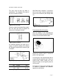
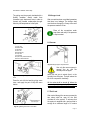
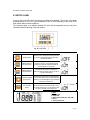
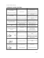
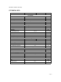
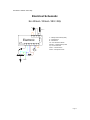
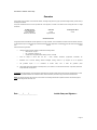
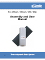
Eco 250esm / 300esm / 280i / 200p
Assembly and User
Manual
Thermodynamic Solar System
R0V0 INDEX
1.
2.
3.
4.
5.
6.
7.
8.
Important
Operating Procedures
Description
Technical Specifications
4.1. Thermodynamic Solar Panel
4.2. Hot Water Cylinder
4.3. Thermodynamic Block
4.4. Fluid, R134a
4.5. Safety Group
4.6. Expansion Tank
4.7. Pressure Reducing Valve
Installation
5.1. Panel Fixation
5.2. Hot Water Cylinder Installation
5.3. Installation of the Thermodynamic Block
5.4. Connections
5.5. Nitrogen Load
5.6. Vacuum
5.7. Fluid Load
5.8. System Start-up
5.9. System Decommissioning
Anomalies / Causes / Solutions
Maintenance Procedures
ANNEXES
Technical Schematics
Electrical Schematics
3
3
4
5
5
5
6
6
7
7
7
8
8
9
9
10
12
12
12
13
13
14
15
16
17
21
Eco 250esm / 300esm / 280i / 200p
1. IMPORTANT
The Eco shall only be started if
the hot water cylinder is fully
filed with water.
The Eco can only function after the
respective refrigerant supply has been
connected.
The electrical input is: ~230 V, 50 Hz.
2. OPERATING PROCEDURES
Please read the following
instructions before start installing
or operating with the solar
system.
The Thermodynamic Solar System Eco shall
only be used for the heating of fresh water
and at the limits indicated on temperature
application! Heating of other liquids, such as
industrial waters or others, shall not be made
with this solar system. The technical rules
(DIN 1988) for the supply of fresh water must
be
taken
into
account.
The thermodynamic solar panel shall be
positioned:
• Outside;
• In a place with good solar capture;
• Respect fixing/fastening rules.
Positioning of the hot water cylinder must not
be done in:
• The open air;
•
In spaces that are potentially
explosive due to vapour or liquid
gases.
Do not turn on the solar system:
• With an empty hot water cylinder;
• Without fluid supply (R134a).
The Eco must always be voltage free when
being worked on.
- Eco construction and assembly procedures
comply with the relevant EC
directives.
VDE, EN and IEC standards
must be complied with when
making electrical connections to the Eco.
Installation, assembly or maintenance of Eco
thermodynamic solar system may only be
carried out by qualified personnel!
2.1 PACKING, STORAGE &
TRANSPORTATION
All Energie – Thermodynamic Solar Systems
products are to be kept in the original
packaging materials and should be stored or
transported in the vertical position - note
there is an arrow to indicate the ‘UP’
direction for packing’s.
European
Certification
EN 60335-1
EN 60335-2-21
Directives
73/23/CEE
93/68/CEE
Page 3 Eco 250esm / 300esm / 280i / 200p
3. DESCRIPTION
The Eco solar system is equipment based on
the
Carnot
principle
compression/
refrigeration principle, denominated as a
Thermodynamic
Solar
System.
The solar panel is the main component and
shall be placed outside for the capture of:
•
•
•
•
Direct and diffuse Solar Radiation;
External air, by natural circulation;
The effect of wind (almost always
existent);
Rain
The differences between temperatures,
stimulated by the previously described
agents, guarantees that Klea (ecological
refrigerant fluid) evaporates in the solar
panel's interior. The absence of glass in the
panel allows for increased thermal exchange
by convection.
After passing through the panel, the Klea
fluid is aspirated by the system’s mechanical
component, the compressor, which in turn
raises the temperature and pressure; it is
then transmitted to the water circuit via a
heat exchanger.
Before the Klea fluid returns to the solar
panel it is necessary for a throttling process
occurs, in other words, pressure reduction
that guarantees the liquid state is once again
achieved, completing the overall cycle.
This operational process, in which we ally
technology with the laws of nature (changing
states of a liquid), demonstrates the power
and the potential of the Eco system.
LEGEND:
1.
2.
3.
4.
5.
6.
7.
8.
Solar Panel
Hot Water
Cylinder
Thermodynamic
Block
Control Panel
Gasket
Profile Kit; screws,
nuts, washers,
wallplugs (6x or
12x)
Copper piping
Electric cable
Fig.2 Overall View of the Equipment Components
Page 4 Eco 250esm / 300esm / 280i / 200p
4. TECHNICAL SPECIFICATIONS
The thermodynamic solar system Eco is
composed by the following components:
- Thermodynamic Solar Panel
- Hot water cylinder
- Thermodynamic Block
- Control Panel
- Pressure reducing valve
- Security group
- Brackets, screws, female, washer, bushing
(6x)
The connections to the panel are Flare SAE
(screw) types:
- 3/8’’ Aspiration (upper connection)
- 1/4’’ Liquid (lower connection)
4.1 Thermodynamic Solar Panel
Fig. 4 Panel Connections
The thermodynamic solar panel is made of
anodized
aluminium
with
corrosion
protection.
4.2. Hot water cylinder
There are two different types of solar panels:
left and right ones (named by the position of
the connections). Although they are
aluminium made, shall be handle with care.
Hot Water Cylinder
Height (mm)
Diameter (mm)
Weight (kg)
250esm
300esm
280i
1500
584
85
1580
680
93
1650
550
40
Tab 2. Hot water cylinder dimensions
4.2.1. Eco 250esm / 300esm / 280i
The hot water cylinder is vertical and shall be
installed that way. It is made of stainless
steel and is thermal insulated with 42 mm
polyurethane.
Thermodynamic Solar Panel
Width
Height
Thickness
Weight
Gross Area / Absorver Area
Tab 1. Solar panel dimensions
2000 mm
800 mm
20 mm
8 kg
1,6 m²
The hot water cylinder is equipped with a
cold-water inlet, hot water outlet, recirculation
inlet and a magnesium anode.
There is a flange type opening in the bottom
of the hot water cylinder for placing the
thermodynamic block.
Page 5 Eco 250esm / 300esm / 280i / 200p
The front part of the block has two valves, of
2 and 3 ways destined for the panel
connections (3/8'' - Aspiration; 1/4'' - liquid)
Expansion
valve
Flange
Fig. 6 Thermodynamic Block (main components)
Fig. 5 Hot water cylinder
1 – Enamelled / Stainless Steel
2- Outside coating
3- Hot water outlet
4- Flange
5- Recirculation inlet
6 – Cold water inlet
7- Magnesium anode
4.3 Thermodynamic block
We call Thermodynamic Block to the
component that transfers the Energy caught
by the solar panel in heat transferred to the
water.
The Thermodynamic Block is connected to
the hot water cylinder through eight M10
screws.
4.4 Fluid, R134a
R134a is an ecological fluid is not harmful to
the ozone layer. It has a high thermal and
chemical stability, low toxicity, is nonflammable and is compatible with the
majority of materials.
PRESSURE/TEMPERATURE GRAPH
Thermodynamic Block
Height
Width
Depth
Weight
Power Input
Power Output
Fluid , R134a
650 mm
310 mm
300 mm
15 kg
390 - 550 W
1690 -2900 W
550 g
It structure is made of galvanized steel that
have the compressor, heat exchanger,
expansion valve, thermostat, pressure
switch, electric resistance.
4.5 Safety Group
The safety group enables the system to be
protected against situations such as;
anomalies in the supply of cold water, the
Page 6 Eco 250esm / 300esm / 280i / 200p
return path of hot water, emptying of the hot
water tank and raised temperatures. It is a
valve body made out of chromed brass, in
accordance with European ISO 9001
standards. The valve is calibrated to open at
7 bar.
NOTE:
Installation of the expansion tank is the
responsibility of the installer. It can normally
be installed into the cold water or hot water
piping system.
4.7 Pressure Reducing Valve
The pressure reducing valve must always be
installed upstream from the safety group and
be ready to operate in
situations in which the network
pressure rises to above 3 bar.
This valve comes equipped with
a manometer.
Fig. 6 Safety Group
1. Threaded orifice (3/4”) for direct connection to the
hot water cylinder.
2. Threaded orifice (3/4") for the input of cold water.
3. Security valve discharge orifice, with opening (1”).
4. Feed Valve.
5. Security valve discharge device command.
6. Inspection lid.
4.6 Expansion Tank
The expansion tank is a device designed to
compensate for any increase in water
caused by a rise in temperature.
This is the recommended
procedure for the correct
installation of this equipment.
Fig. 8 Pressure reducing valve
Characteristics:
•
•
•
•
•
•
Chromed Brass Body
Max. upstream pressure: 16 bar.
Downstream pressure 1 – 6 bar.
Max. operating temperature: 65° C
Manometer: 0 to 10 bar
¾” Threaded orifice (entry and exit).
Fig. 7 Expansion tank installation diagram
Page 7 Eco 250esm / 300esm / 280i / 200p
5. INSTALLATION
Assembly Sequence
•
•
•
•
•
•
•
•
•
Solar Panel(s)
Hot Water Cylinder
Thermodynamic Block
Refrigerating connections (suction,
liquid)
Hydraulic connections
Electrical connections
Nitrogen supply
Vacuum
Installation start-up
Fig. 9 Profile fixing diagram
5.1 Panel Fixation
It is important to take the characteristics of
the installation location and the inclination
angle of the panels into account. In order to
get maximum benefit from incidental Solar
Radiation, the panels must be at an
inclination of between 10° - 85° in relation to
the horizontal position, preferably orientated
towards the South.
It may be installed in a wall, façade, roof,
plain roof or other.
The panel comes already supplied with 6 M8
screws on the lateral tabs. The distance
between the holes in the location where the
panel is to be fixed must coincide with the
panel holes (Fig. 13):
Fig. 10 Panel profile fixing process
1.
2.
3.
4.
5.
6.
7.
Profile (aluminium)
Plastic wall plug
Self-tapping screw (M6x40)
Washer M6
Screw (M6x20)
Nut M6
Panel
Page 8 Eco 250esm / 300esm / 280i / 200p
Side B
Side A
Fig. 13 Panel types (left and right)
Fig. 11 Panel fixing diagram
5.2 Hot Water Cylinder Installation
The system comes with six sets of: profiles,
screws, nuts, washers, wall plugs.
The panel has 3 small profiles (side A) and 3
large profiles (side B) which shall be fixed
according stipulations in the diagram, giving
the panel the desired level of inclination.
The profile shall be fixed to a base (e.g. a
roof) via the provided plastic wall plugs and
the self-tapping M6 screws.
The M6 screws and the respective nuts and
washers shall make the panel fixing to the
profiles.
The hot water cylinder shall be installed in a
cool and dry location with easy access and
protected from all weather conditions. The
choice of location must allow for easy
assembly of the Thermodynamic Block.
The spot where the hot water
cylinder shall be installed must
have nearby:
•
•
•
•
•
A cold water point
Hot water point
Drainage.
Recirculation (if it exists).
Electrical point, 230 V/50Hz
Observe that in some hot
water
cylinders
the
hydraulic connections are
at the back of the device, it
hence being necessary to
consider the spacing between them and the
wall.
Fig. 12 Panel hole drilling diagram
The solar panel shall always be installed with
the connections facing downwards.
5.3 Installation of the Thermodynamic
Block
Refer to the 2 existing different types of
panels; right panels (A) and left panels (B).
Before installing the Thermodynamic block,
make sure that the heat exchanger is not in
contact with the resistance casing and the
thermostat. To check this, use a multimeter
(in the continuity position), positioning a
connector on the heat exchanger and the
Page 9 Eco 250esm / 300esm / 280i / 200p
other on the block’s support structure
(compressor or flange) and verify that no
continuity actually exists.
DHP according to the ISO1337 standards
and EN12735).
Piping Diameters
- The Thermodynamic Block is coupled into
the existing flange (at the lower part of the
hot water cylinder).
- Correctly place the sealing gasket before
tightening up between the flanges.
GAS
(aspiration)
mm
inches
9,52
3/8’’
LIQUID
mm
6,35
inches
1/4’’
Tab 4. Piping diameter (aspiration and liquid)
In any circumstance shall be
used sanitary water copper
tubes.
Panel Connections
Take off the covers of the copper pipes ends.
Place the extremity of the pipe turned down
and cut the pipe at a distance intended.
Remove the existing barbs.
Fig. 14 Coupling of the Block to the hot water cylinder
- Place the heat exchanger into the hot water
cylinder, taking special care upon its
placement, avoiding any damage.
- The coupling of the Thermodynamic Block
to the water cylinder shall be done with the
supplied screws. Tightening of the screws
must be done with a crosshead screwdriver,
guaranteeing air-tightness.
The hot water cylinder shall be properly fixed
in place at the moment the Thermodynamic
Block is positioned, thus avoiding any slight
drop in the unit, considering that there will be
a centre of gravity dislocation.
Fig. 16 Barbs removal
Remove the connections nuts from the panel
and place them aside of the pipe. Make a
conical shape at the end of the pipes with an
appropriate tool.
5.4 Connections
The copper tubes used to connect the
thermodynamic block to the solar panel shall
be refrigerant type without sewage (Type Cu
Fig. 17 Conical shape
Page 10 Eco 250esm / 300esm / 280i / 200p
The conic must not have any barbs or
imperfections. The longitude of the walls of
the conic one must be uniform.
After finished the connection, it must prove
that no gas escape exists by applying soap
foam on the connections (with nitrogen load
on).
Fig. 18 Correct conic shape
Place the nut with the hand and then rotate it
with two keys that shall be applied like
torsion pair, as the figure indicates.
Fig. 21 Connection Thermal Protection
Thermodynamic Block Connection
After the installing of the thermodynamic
block to the hot water cylinder with the 8 M10
screws, the connections shall be made
Fig. 19 Tight the connections
An insufficient tightening will cause gas to
escape. An extreme squeeze of the coupling
will damage the pipe and will cause the gas
to escapes.
Repeat the procedure used to connect the
panel to the copper pipes.
Cut of the pipe in the required length with the
extremity directed towards down. Clean the
existing barbs. Before making the conic
shape in the pipe, do not forget to place the
nut in the pipe.
Fig. 20 Tightening with proper keys
Pipe diameter
mm
(inches)
6,35
(1/4’’)
9,52
(3/8’’)
Tab.5 Tightening
Torsion
Nm
14 -18
33 - 42
The entrance of piping into the building shall
be finished to guarantee total resistance
against rain and moisture.
Page 11 Eco 250esm / 300esm / 280i / 200p
The piping must be properly insulated with a
flexible insulation sleeve made from
(Armaflex type) elastomeric foam in order to
prevent any possible condensation brought
about by low temperatures in the liquid.
5.5 Nitrogen Load
After connections been concluded guarantee
that there is no leakage. The nitrogen load
must be done through the 3 ways valve until
the pressure reaches 12 bar.
Place all the connections under
soap foam and verify if the pressure
is kept constant.
Fig. 23 2 and 3 ways valves details
5.6 Vacuum
1- 3 way valve
2- Pressure Inlet
3- Valve Bush
4- Valve rotor
5- Hexagonal Key
6- 2 way valve
7- Conical Nut
8- Liquide Line (smallest diameter)
9- Gas line (bigest diameter)
Fig. 26 Nitrogen pipes and panel load
Use only the vacuum pump to
remove the air and the
humidity from the pipes.
Fig. 24 Connecting the pipes to the thermodynamic
block
Press the nut with the hand by giving some
turns, and apply the pair of keys like seen
before.
Never use the gas to extract the air or the
humidity from the pipes. That will reduce the
life of the compressor drastically.
All the valves shall be turned off before the
vacuum is start being made. This way the
vacuum will only be done inside the tubes.
5.7 Fluid Load
After carried through the vacuum process the
two valves shall be open for the fluid
circulate all in the system. To enhance that
the system is supplied with a pre-load that is
enough for a maximum length of 10 meters
Fig. 25 Tightening the tubes to the valves
Page 12 Eco 250esm / 300esm / 280i / 200p
between the solar panel and the
thermodynamic block. For situations that this
length is exceed is necessary to have to
make adjustments of the load. These
adjustments shall be done by the
compression pipe with the system stopped.
The Eco is equipped with an electrical
resistance heating process in case of any
eventual system breakdown. If it is
necessary to use this function, press the
Electrical Support (3) ON/OFF button on the
command panel and the water will be heated
via electrical resistance.
5.8 System Start-up
5.9 System Decommissioning
The Eco commissioning is assured by the
correct installation achieved and by the
respect of all installation instructions.
Increasing water temperature from 10° C to
55° C will vary between 4 to 8 hours,
depending on weather conditions and type of
installation.
It is always possible to do a tune of thermal
expansion valve to adapt the system to a
suitable outside weather conditions by the
temperatures extrapolation method.
At the end of the product lifetime,
decommissioning of the system should be
undertaken by an installer or suitable
qualified plumber and / or electrician (if
required). All materials used in this product
can be passed to your local material
recycling centre for disposal - refer to local
council regulations for details.
Fill the hot water cylinder with water and
purge the existing air, opening a hot water
tap/faucet.
Check if the valves are properly working and
if the system is filled with fluid.
There aren’t any failure problem when
starting the system under frost conditions.
To conclude the installation process it is
necessary to connect the electrical cable to
the 230V plug socket, securing the control
panel
with
two
M6
screws.
To turn the apparatus on, press the general
ON/OFF button (1) on the control panel.
Afterwards, press the ON/OFF button on the
Solar System (2). The display must give
information that the system is operational
(ON). Heating up of the water will now begin.
Page 13 Eco 250esm / 300esm / 280i / 200p
6 CONTROL PANEL
You may start up the Eco if all instructions have been accomplished. The rise up of the water
temperature from 10ºC to 55ºC may vary between 2 and 10 hours depending on the model of the
solar system and the outside conditions.
The command panel is an interface between the user and the equipment and you may have
information about the working of the solar system.
Fig. 23 Control Panel
Nº
Button
Display
Name
Function
1
ON/OFF Button
Allows the user to switch power ON or power OFF.
If you press this button the display present the
following information:
2
ON/OFF Button for
the Solar System
Works for turning the power ON/OFF only for the
compressor. It has a one-minute delay before
turning the system OFF, between that time the
word ON will blink on the screen.
3
ON/OFF Button for
Electrical Backup
This shall only be turned on an emergency
situation to ensure hot water to the user in case of
a system malfunctioning.
4
5
This allows the modification working parameters.
Programming Button Do not use this unless you are a trained technician
(Factory Only)
otherwise you could damage the solar system that
will result in guarantee lost.
Anti-Legionella
Button
Activate the anti-legionella program. This will rise
up the temperature of the water until 65ºC. Only
turn ON this program if you do not predict to have
any water consuption on the next 8 hours.
Legend
a- Temperature
b- Output ON
c- State of the System (OFF, ON, ALM)
d- Errors
e- Factory Parameters
Page 14 Eco 250esm / 300esm / 280i / 200p
7 ANOMALIES / CAUSES / SOLUTIONS
ANOMALY
CAUSE
SOLUTION
Verify the presence of 230 V A/C at
system input source.
System turned off
Check that the system is turned on.
The water is cold and the compressor
does not function.
(Display shows no information)
Make sure electrical cabling is not
disconnected.
The water is cold and the compressor
does not function.
Protection system activated
Check electrical protection (the Fuse).
(Display shows no information)
Condenser is covered with lime
Check for Low Pressure breakdown
(“LP” Error).
Carry out effective cleaning.
Cold or lukewarm water, but
compressor is functioning.
Excessive water consumption
Wait for Thermal Charging to occur.
Alteration in electronic parameters
Substitute the electronic panel.
Refrigerant fluid leakage
Badly connected voltage input
Refrigerant fluid leakage
Condenser is covered with lime
Detect and repair the leak.
Check voltage feed (230 V).
Detect and repair the leak.
Carry out effective cleaning.
Check if there is power supply.
Check the electrical cables connection
for the control panel.
Check the system fuses.
The compressor periodically stops and
starts
Lack of power
The display do not present any
information
Safety thermostat ON
LP Error on display:
Fluid missing in the solar panel circuit
Rearm the safety thermostat
Turn ON the electrical backup if
needed.
Outside temperatures too low
Every time that a LP error occurs the
system will have a 20 minutes delay,
during that period the word “ON” shall
blink in the screen.
Solar system is shut down
Press the ON/OFF button for the solar
system
Power supply malfunction
Check the fuses.
Excess of water usage
Wait for the water to warm up
The display presents the word:
The display presents the following
information but the water is cold:
Page 15 Eco 250esm / 300esm / 280i / 200p
Technical Support Notes:
- Melted Compressor fuse; start-up condenser capacity must be checked.
- Melted RES fuse; the possibility of a short-circuit must be verified (e.g. electrical resistance).
- Safety thermostat operational; electronic panel parameters must be checked.
8. MAINTENANCE PROCEDURES
Magnesium Anode
The anode must be removed in order to check it state.
If the magnesium anode is letting water pass it will be necessary change it. The period between
changing the anode is always dependent of the water quality in each location. In areas with raised
concentrations of soluble solids, the anode needs to be changed with less regularity, whereas in
situations with low concentration, the anode needs to be changed with greater regularity. Therefore
the magnesium anode state shall be checked at least one time per year.
Pressure Reduction Valve Filter
The following procedure shall be done for periodic (maximum once every two years) cleaning of
the pressure reduction valve filter:
1.
2.
3.
4.
Close the passage of water from the network.
Turn in an anti-clockwise direction after relieving the spring’s tension.
Draw back the lever/handle.
Remove the filter and clean it.
Page 16 Eco 250esm / 300esm / 280i / 200p
9 TECHNICAL DATA
System
Eco 280i / 200p
Eco 250esm / 300esm
UNITS
Potential Data
Thermal Power
1690 – 2900
W
Absorbed Power
390 – 550
W
1200
W
Electric Support Power
Compressor
Hermetic / Piston
Type
Noise Level
39
Thermodynamic Solar Panel
dB
Material
High Performance Anodised Aluminium
Quantity
1
2000 x 800 x 20
mm
12 /1,2
15 / 1,5
bar / Mpa
bar / Mpa
Min. Temperature
120
-5
ºC
Min, Exposure Temperature
- 40
ºC
Dimensions
Max. operating pressure
Test pressure
Max. Temperature
ºC
Hot Water Cylinder
Material
Stainless Steel
Enamelled
Polyurethane
Insulation
6 / 0,6
Max. working pressure
Test pressure
10 / 1,0
90
Max. Operating Temperature
bar / Mpa
bar / Mpa
ºC
Magnesium Anode
Protection
Fluid
Type
R134a
Quantity
1100
kg
Copper
1/4”
inch
3/8”
inch
230 / 50
V/Hz
Compressor Fuse
6.3 T
A
General Fuse
6.3 F
A
Connections (piping)
Type
Liquid Line
Aspiration Line
Electronic Panel
Feed
Page 17 Eco 250esm / 300esm / 280i / 200p
10 DIMENSIONS AND TECHNICAL SCHEMATICS
Eco 250esm
4
4
3
2
H
A
G
B
C
F
1
D
E
1- Cold water inlet
2- Recirculation
3- Hot water outlet
4- Magnesium anode
A
B
C
D
E
F
G
H
1
mm
70
1050
1450
584
2
3
4
3/4''
5/4''
inches
820
350
800
1500
3/4''
3/4’’
Page 18 Eco 250esm / 300esm / 280i / 200p
Eco 280i
3
3
2
2
B
C
H
4
1
A
1
D
E
1- Cold water inlet
2- Recirculation
3- Hot water outlet
4- Magnesium anode
A
B
C
D
E
H
1
mm
260
750
1280
550
2
3
4
3/4'’
1’ 1/4’’
inches
800
1650
3/4'’
1/2'’
Page 19 Eco 250esm / 300esm / 280i / 200p
Eco 300esm
3
3
4
4
2
A
G
B
H
F
1
D
E
1- Cold water inlet
2- Recirculation
3- Hot water outlet
4- Magnesium anode
A
B
D
E
F
G
H
1
2
mm
90
770
680
930
3
4
1’’
5/4’’
inches
350
850
1580
1’’
1’’
Page 20 Eco 250esm / 300esm / 280i / 200p
Eco 200p (Wall Hanging)
2
2
3
4
B
I
C
F
H
E
4
A
G
1
J
D
4
3
1
1- Cold water inlet
2-Magnesium anode
3- Hot water outlet
4- Fixation
2
A
B
C
D
E
F
G
H
I
J
1
mm
180
750
900
800
370
2
3
4
inches
920
280
1250
1030
235
3/4’’
1’’1/4
3/4’’
Page 21 Fixation
Eco 250esm / 300esm / 280i / 200p
Electrical Schematic
Eco 250esm / 300esm / 280i / 280p
LP
Sonda 1
a
Fuse 2
10 11 12 13 14 15
Electrónico
Electronic
Fuse 1
1 2 3 4 5 6 7 8 9
b
T
C
F
N
T –Legenda
Safety Thermostat (75ºC) T - Termóstato de segurança (75ºC)
C – Compressor C- Compressor
R – Resistance R- Resistência
LP – Low Pressure Switch LP- Pressostato de Baixa
Sonda1 – Temperature probe Sonda1- Sonda de temperatura
a,b – Extra contacts a, b- Contactos extra
Fuse 1 – General fuse Fuse 1- Fusível Geral
Fuse2 – Compressor fuse Fuse 2- Fusível Compressor
C
T
R
L/N/T 230VAC 50Hz
Page 22 Eco 250esm / 300esm / 280i / 200p
Guarantee
This guarantee covers all defects to the confirmed materials, excluding the payment of any type of personal damage indemnity caused directly or
indirectly by the materials.
The periods indicated below start from the purchase date of the apparatus, 6 months at the latest from the leaving date from our storage
warehouses.
Hot Water Cylinder
3 Years: Stainless Steel
2 Years: Enamelled
Manufacturer Guaranteed
Solar Panel
Thermodynamic Block
5 Years
Against Corrosion
2 Years
Guarantee Exclusions
The guarantee ceases to be effective when the apparatus is no longer connected, used or assembled in accordance with manufacturer instructions,
or if there has been any form of intervention by unauthorised technicians, has the appearance of modifications and/or if the series number appears to
have
been
removed
or
erased.
Further exclusions from guarantee:
•
Hot water cylinders have been operating in water with the following indexes:
o
Active chlorine > 0.2 ppm
o
PH < 6 (Sorensen scale at 25° C).
o
All water has a value greater than the VMA, by decree – law 74/90
•
Parts
•
Breakdown due to incorrect handling, electrical discharges, flooding, moisture or by improper use of the apparatus.
•
The
•
The guarantee lapses if this certificate is incorrectly filled in, if it is violated or if it is returned after more than 15 days have passed since
the purchase date of the apparatus.
are
subject
guarantee
to
lapses
natural
if
it
wear
is
and
tear
transferred
–
to
levers,
another
switches,
owner,
resistances,
even
if
programmers,
within
the
thermostats,
guarantee
etc.
period.
ATTENTION: Technical assistance costs, even within the guarantee period, shall be supported by the customer (Km and assistance time). In cases
where there is no justifiable breakdown and subsequent need for technical assistance, the client will pay for lost technical assistance time.
NOTE: This sheet should remain with the manual, for the customer. The following sheet shall be completed and must be returned to Energie est,
Lda. otherwise the guarantee will not be valid.
Date : _____/_____/__________
Installer Stamp and Signature :
Page 23