1
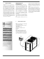
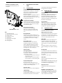
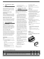
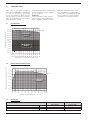
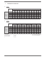
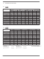
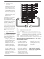
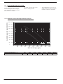
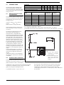
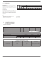
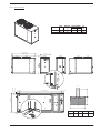
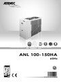
L
M
UCONTRO
OD
SCROLL
AXIAL
CHILLERS AND HEAT PU
PUMPS
UM
- Technical - Installation manual
ANL 100-150HA
60Hz
EN
IANL60HzPY. 1007. 6755517_00
Dear Customer,
Thank you for choosing an AERMEC product. This product is the result of
many years of experience and in-depth engineering research, and it is
built using top quality materials and advanced technologies.
In addition, the CE mark guarantees that our appliances fully comply with
the requirements of the European Machinery Directive in terms of safety.
We constantly monitor the quality level of our products, and as a result
they are synonymous with Safety, Quality, and Reliability.
Product data may be subject to modifications deemed necessary for
improving the product without the obligation to give prior notice.
Thank you again.
AERMEC S.p.A
AERMEC S.p.A. reserves the right at any moment to make any modifications considered necessary to improve our
products and is not obliged to add these modifications to machines that have already been fabricated, delivered
or are under construction.
SUMMARY
1.
General warnings ........................................................6
2.
Product identifi cation.................................................6
3.
Description and choice of unit ..................................7
4.
Configurator .................................................................8
5.
5.1.
5.2.
5.3.
5.4.
5.5.
5.6.
Description of the components .................................9
Cooling circuit ..............................................................9
Frame and fans ............................................................9
Hydraulic circuit ...........................................................9
Control and safety components .............................10
Electric components .................................................10
Electronic modu control adjustment.......................10
6.
Accessories compatibilty table ...............................10
7.
Technical data...........................................................11
8.
8.1.
8.2.
8.3.
Operating limits ..........................................................12
Cooling mode ............................................................12
Heating mode (for heating pump) .........................12
Project data ...............................................................12
9.
9.1.
9.2.
Performance in cooling mode.................................13
ANL 100 ......................................................................13
ANL 150 ......................................................................13
10.
10.1.
10.2.
Performance in heating mode ................................14
ANL 100 H...................................................................14
ANL 150 H...................................................................14
11.
11.1.
11.2.
Ethylene glycol solutions ........................................... 15
How to interpret glycol curves .................................15
Static pressures useful to the system........................16
12.
12.1.
12.2.
Storage tank .............................................................. 17
Minimum/maximum content of system water ......17
Expansion vessel calibration ....................................17
13.
Sound data ................................................................18
14.
Parameter calibration of safety and control .........18
15.
15.1.
Receiving the product and installation ....................... 20
Receiving the product and handling .....................20
16.
Internal hydraulic circuit .........................................21
17.
External hydraulic circuit anl (not provided) ..........21
AERMEC S.p.A.
I-37040 Bevilacqua (VR) Italia – Via Roma, 996
Tel. (+39) 0442 633111
Telefax 0442 93730 – (+39) 0442 93566
www.aermec.com - [email protected]
ANLH
SERIAL NUMBER
CE DECLARATION OF CONFORMITY
We, the undersigned, hereby declare under our own responsibility that the
assembly in question, defined as follows:
NAME
ANL
TYPE
WATER/AIR chiller, heat pump
MODEL
To which this declaration refers, complies with the following harmonised standards
CEI EN 60335-2-40
Safety standard regarding electrical heat pumps, air conditioners and
dehumidifiers
CEI EN 61000-6-1
CEI EN 61000-6-3
Immunity and electromagnetic emissions for residential environments
CEI EN 61000-6-2
CEI EN 61000-6-4
Immunity and electromagnetic emissions for industrial environments
EN378
Refrigerating system and heat pumps - Safety and environmental requirements
EN12735
Copper and copper alloys - Seamless, round copper tubes for air conditioning and refrigeration
UNI 12735
Seamless, round copper tubes for air conditioning and refrigeration
UNI 14276
Pressure equipment for cooling systems and heat pumps
Therefore complying with the essential requisites of the following Directives:
- Directive LVD: 2006/95/CE
- Electromagnetic compatibility Directive 2004/108/CE
- Machinery Directive 2006/42/CE
- PED Directive regarding pressurised devices 97/23/CE
The product, in agreement with Directive 97/23/CE, satisfies the Total quality Guarantee procedure (form H) with certificate n.06/270-QT3664 Rev.5 issued by the notified body n.1131 CEC via Pisacane 46 Legnano (MI) - Italy
The person authorized to compile the technical file is: Massimiliano Sfragara - 37040 Bevilacqua (VR) Italy–Via
Roma, 996
Bevilacqua
07/07/2010
Marketing Director
Signature
1.
GENERAL WARNINGS
AERMEC ANLs are constructed according to the recognised technical standards and safety regulations. They have been designed for
air conditioning and the production of domestic hot water (DHW)
and must be destined to this use
compatibly with their performance
features. Any contractual or extracontractual liability of the Company is excluded for injury/damage
to persons,animals or objects owing
to installation,regulation and maintenance errors or improper use. All
uses not expressly indicated in this
manual are prohibited.
PRESERVATION OF THE
DOCUMENTATION
The instructions along with all the
related documentation must be given to the user of the system, who
assumes the responsibility to conserve the instructions so that they
are always at hand in case of need.
Read this sheet carefully; all works
must be performed by qualified
staff, according to Standards
in force on this subject in different countries. (Ministerial Decree
329/2004).
The appliance must be installed in
such a way as to enable maintenance and/or repairs to be carried
out.
The appliance warranty does not
2.
Standards and Directives respected on
designing and constructing
the unit
Safety:
Machinery Directive
2006/42/CE
Low Voltage Directive
LVD 2006/95/CE
Electromagnetic compatibility
Directive
EMC 89/336/CEE
Pressure Equipment Directive
PED 97/23/CE EN 378,
UNI EN 14276
Electric part:
EN 60204-1
Protection rating
IP24
Acoustic part:
ISO DIS 9614/2
(intensimetric method)
Performance data:
norma UNI EN 14511
Refrigerant GAS:
This unit contains fluoride gases
with greenhouse effect covered by the Kyoto Protocol.
Maintenance and disposal
must only be performed by
qualified staff.
R410A GWP=1900
6
cover the costs for ladders, scaffolding, or other elevation systems
that may become necessary for
carrying out servicing under warranty.
Do not modify or tamper with the
chiller as dangerous situations can
be created and the manufacturer
will not be liable for any damage
caused. The validity of the warranty
shall be void in the event of failure
to comply with the above-mentioned indications.
PRODUCT IDENTIFI CATION
ANL are identified by the following:
−PACKAGING LABEL
that includes the product identification data
−TECHNICAL PLATE
Placed on the right strut side
(see fig.1)
NOTE:
If the identification plate, or any
other means to identify the product, is tampered with, removed
or missing, installation and maintenance operations are hampered
TECHNICAL
PLATE
PACKING
LABEL
3.
DESCRIPTION AND CHOICE OF
UNIT
They are available in the following
versions:
ANL R410A coolers and air cooled
heat pumps have been designed
and manufactured to satisfy heating and cooling needs and the
production of domestic hot water
(DHW) in medium to small commercial or residential buildings.
− HEAT PUMP ANL H
Winter to summer switch-over
functioning can be applied via the
cooling circuits.
Possibility of producing DHW
(DCPX mandatory)
− STORAGE AND PUMP
These units, available in 2 sizes,
have extremely silent functioning
and are highly efficient and reliable, thanks to the use of exchangers with a large exchange
surface and low-noise high-efficiency scroll compressors.
NOTES
Refer to the configurator for the set-ups
that are not possible.
ce that the oil in the sump compressor
is heated for at least 8 hours using the
electrical resistances. The sump resistance is powered automatically when the
unit stops as long as the unit is live.
WARNING
Before use (or after a prolonged period
of suspension) of units with low air
temperature functioning and also with
a heat pump, it is of extreme importan-
7
4.
CONFIGURATOR
1,2,3
4,5,6
7
8
9
10
11
12
13
ANL
100
H
A
°
°
°
°
6
FIELD
1, 2 ,3
CODE
ANL
4, 5, 6
SIZE
100 -150
7
MODEL
H
Heat Pump
VERSION
A
with storage tank and pump
8
9
HEAT RECOVERY
°
10
without heat recovery units
COILS
°
in aluminium
11
FIELD OF USE
temperature of water produced up to 4 °C / 39°F
°
12
EVAPORATOR
standard, by PED
°
13
SUPPLY
6
7
3~220-60Hz
3~460-60Hz
Example of configurator: ANL100HA°°°°6
8
5.
Examples of hydraulic circuits
the diagram shown here are an
example
NENTS
5.1.
2
COOLING CIRCUIT
Compressor
High efficient scroll type on anti-vibration mounts, activated by a 2-pole
electric motor with internal circuit
breaker protection.
They are supplied, as standard, with an
electric anti-freeze resistance, powered automatically when the unit stops
as long as the unit is live.
6
7
4
3
8
5
1
DESCRIPTION OF THE COMPO-
Air-side heat exchanger
Made with copper pipes and aluminium louvered fins blocked by mechanical expansion of the pipes. Provided
with protective grid.
Water-side heat exchanger
VERSIONE A 100 - 150
KEY
1 Circulator/pump
2 Differential pressure switch
3 Safety valve
4 Exapnsion vessel
5 Water filter
6 Plate heat exchanger
7 Vent valve
8 Storage tank
Water-side heat exchanger
Plate type, isolated externally with
closed cell material to reduce heat
loss.
Dehydrator filter
Mechanical type filter realised in ceramics and hygroscopic material, able
to withhold impurities and any traces
of humidity present in the cooling
circuit.
Thermostatic valve
Mechanical valve, with external
equaliser positioned at evaporator
outlet, modulates the flow of gas to
the evaporator, depending on the
heat load, in order to ensure a correct
heating level of the intake gas.
Solenoid valve
of hot gas injection
The valve positioned between the
compressor and the thermostatic
valve outlet controls:
−
Defrosting cycles without having to
reverse the cycle
−
Safety capacity control if the pressure should rise on the pressing line
Cycle reversing valve
(for heat pump only.)
Reverses the flow of refrigerant on
variation of summer/winter mode and
during any defrosting cycles.
One-way valve
Allows one-way flow of the refrigerant.
Liquid storage
(for heat pump only.)
Compensates the difference in volume
between louvered fin coil and plate
exchanger, withholding excess liquid
during winter functioning.
5.2.
FRAME AND FANS
Ventilation unit
Helical type, balanced statically and
dynamically. Electric fans are protected electrically by magnet-circuit
breakers and mechanically by antiintrusion metal grids, according to IEC
EN 60335-2-40 Standard.
Support frame
Made in hot galvanised sheet steel
with suitable thickness and painted
with polyester powders able to resist
atmospheric agents through time.
5.3.
HYDRAULIC CIRCUIT
Circulation pump (circulator)
Differential pressure switch
Positioned between inlet and outlet of
evaporator. It has the task of controlling that there is water circulation, if this
is not the case it blocks the unit.
Water filter
This allows to block and eliminate any
impurities present in the hydraulic
circuits. It contains a filtering mesh with
holes that do not exceed one millimetre.
It is indispensable in order to prevent
serious damage to the plate exchanger.
Storage tank
It is required to reduce the number of
peaks of the compressor and to even
the temperature of water to be sent to
the utilities.
- for ANL 100 - 150 da [100 l]
Vent valve
(only for versions with hydronic unit or
with a pump)
Manual type, discharges any air pockets present. It is interrupted by a cock
to facilitate any replacement.
Expansion vessel
membrane type with nitrogen preload.
Hydraulic circuit safety valve
Calibrated at 6 BAR (87 psi) and with
conveyable discharge, intervenes by
discharging the overpressure in the
case of pressure anomalies.
9
5.4.
CONTROL AND SAFETY COMPONENTS
High pressure pressure switch (HP)
With fixed calibration, placed on high
pressure side of cooling circuit, inhibits
functioning of compressor if abnormal
work pressure occurs.
Low pressure transducer (TBP)
Heat pump (H)
Placed on low pressure side of cooling
circuit, it communicates the work pressure to the control board, generating a
pre-alarm if abnormal pressure occurs.
High pressure transducer (TAP)
Placed on high pressure side of cooling
circuit, it communicates the work pressure to the control board, generating a
pre-alarm if abnormal pressure occurs.
5.5.
ELECTRIC COMPONENTS
Electric Control Board
Contains the power section and the
management of controls and safety
devices. It is in compliance with the IEC
60204-1 Standard and the Directives regarding electromagnetic compatibility
EMC 89/336/EEC and 92/31/EEC.
Door-lock isolating switch
The electric control board can be accessed by removing the voltage. Act on
the opening lever of the control board
itself. This lever can be locked using one
or more padlocks during maintenance
interventions to prevent the machine
being powered up accidentally.
Control board
Allows complete control of the appliance.
For a more in-depth description please
refer to the user manual.
− compressors magnet circuit-breaker
protection.
− fans magnet-circuit breakers protection;
− auxiliary magnet circuit-breaker
protection
− Heat exchanger inlet/outlet water
temperature probes
− Gas temperature probe one on the
6.
−
5.6.
for pressing line and coil
External air temperature probe WITH
DCPX ACCESSORY
ELECTRONIC MODU CONTROL
ADJUSTMENT
MODU_CONTROL
b. Compressor ON/OFF
c. Functioning mode (hot/cold)
d. Alarm active
Probes, transducers and parameters
display
a. Water outlet
b. Water inlet
c. Coil temperature (heat pumps)
d. Pressing line gas temperature
e. External air temperature (heat pumps,
cooling only with DCPX and probe)
f. Flow pressure (heat pumps)
g. Intake pressure (heat pumps)
h. Temperature error (sum of the proportional and integral error)
i. Stand-by times for start-up/switch-off
of the compressor
Alarms management
a. Low pressure
b. High pressure (primary alarm: the
pressure switch directly blocks power
supply to compressor)
c. High discharge temperature
d. Anti-freeze
e. Water differential flow meter/pressure
switch
f. Alarm on the ∆T
Temperature control of the outlet water
with proportional-integral algorithm:
maintains average outlet temperature
at value set
−
Self-adapting differential
switch: guarantees minimum functioning times of the compressor in
systems with low water content.
− Intelligent defrosting for pressure
reduction: allows to determine
when the coil is effectively defrosted,
avoiding useless defrosting
− Hot gas injection defrosting: In this
way the machine consumes less
energy, increases heating capacity,
keeps efficiency high and prevents
temperature drops at the terminals
(very important in plants with low
water content Emergency defrosting by cooling cycle reversing: to
overcome more serious conditions
− Alarms with automatic reset with
− Set-point compensation with exterlimited number of re-starts before
nal temperature (with external air
blockin
probe accessory): reduces energy
− ON/OFF from external contact
consumption
− Change season from external con− Condensation check based on the
tact
pressure rather than on temperature
for absolute stability (with DCPX revs. ATTENTION:
adjuster accessory)
►DCPX not supplied
− Inverse condensation check for the
heat pump functioning mode also
► For further information please refer to
in summer (withDCPX revs. adjuster
user manual
accessory).
− Pre-alarms with automatic reset: in
the case of alarm, a certain number
of re-starts are allowed before the
definitive block.
− Alarm on the∆T: to identify wiring
errors (reverse rotation) or blocked
cycle reversing valve.
− Compressor functioning hours count
MODUCONTROL
− Compressor peak count.
− Historical alarms
− Autostart after voltage drop.
− Local or remote control
Display of unit status:
a. Voltage presence
ACCESSORIES COMPATIBILTY TABLE
ACCESSORIES ANL
ANTI-VIBRATION MOUNTS
VT
10
CONTROL PANEL
Group of four anti-vibration mounts to be installed under the sheet steel base in the prepared points.
They are used to reduce vibrations produced by the compressor whilst functioning.
MODELS
100
150
VERSION
100
150
A
15
15
7.
TECHNICAL DATA
COOLING
Cooling capacity
Total input power [*]
Water flow rate
HEATING
Heating capacity
Total input power [*]
Water flow rate
ENERGY INDEXES
EER [*]
COP [*]
IPLV
ELECTRICAL DATA
Input current on COOLING
Input current on HEATING
Maximum current(FLA)
Peak current (LRA)
MCA
MOP
COMPRESSORS (SCROLL)
Number/Circuit
Power supply
Input current
Useful head (1)
STORAGE TANK
Water storage tank
HYDRAULIC CONNECTIONS
Inlet for water circulation
Outlet for water circulation
SOUND DATA
Sound power
Sound pressure (2)
DIMENSIONS UNIT (PALLET)
Height
Width
Depth
DIMENSIONS ONLY UNIT
Height
Width
Depth
Weight when empty
100HA
150HA
220-3-60 Hz
460-3-60 Hz
220-3-60 Hz
460-3-60 Hz
220-3-60 Hz
460-3-60 Hz
kW / Tons
kW / Tons
kW
kW
l/h / gpm
l/h / gpm
23.11 / 6.57
23.11 / 6.57
8.24
8.24
3974 / 17.50
3974 / 17.50
28.69 / 8.15
28.69 / 8.15
9.48
9.48
4934 / 21.72
4934 / 21.72
220-3-60 Hz
460-3-60 Hz
220-3-60 Hz
460-3-60 Hz
220-3-60 Hz
460-3-60 Hz
kW / BTU
kW / BTU
kW
kW
l/h / gpm
l/h / gpm
27.77 / 94,840
27.77 / 94,840
8.29 / 28,312
8.29 / 28,312
4776 / 21.03
4776 / 21.03
32.78 / 111,949
32.78 / 111,949
9.57 / 32,683
9.57 / 32,683
5639 / 24.83
5639 / 24.83
220-3-60 Hz
460-3-60 Hz
220-3-60 Hz
460-3-60 Hz
220-3-60 Hz
460-3-60 Hz
220-3-60 Hz
460-3-60 Hz
220-3-60 Hz
460-3-60 Hz
220-3-60 Hz
460-3-60 Hz
220-3-60 Hz
460-3-60 Hz
220-3-60 Hz
460-3-60 Hz
220-3-60 Hz
460-3-60 Hz
Resistance sump compressor
Capacity controls
FANS (AXIAL)
Quantity
Air ow rate
Input power
Input current
EVAPORATORS (PLATES)
Quantity
CHARGE
Gas refrigerant (R410A)
Oil compressor
CIRCULATION PUMP
Input power
M.U.
11.43
11.43
3.35
3.35
4.80
4.80
11.7
11.7
3.43
3.43
5.19
5.19
29.6
14.2
29.8
14.3
70.4
36.8
162.4
93.1
67
36.4
106.1
53.1
32.4
15.5
32.7
15.6
84.6
45.8
187.6
108.9
80.6
44.9
127.3
66.8
n°
n°xW
%
2/1
2x35
0-50-100
2/1
2x35
0-50-100
n°
mc/h
kW
A
2
13.200
0.6
2.6
2
12.000
0.6
2.6
n°
1
1
12.7 / 27.99
2x1.6 / 2x3.53
16.0 / 35.27
2x1.6 / 2x3.53
kPa / ft/h
0.75
3.6
1.7
92 / 31
1.5
6.2
3.0
120 / 40
l / gal
100/26.41
100/26.41
Ø
Ø
1"¼
1"¼
1"¼
1"¼
dB(A)
dB(A)
76.0
44.0
77.0
45.0
mm / in.
mm / in.
mm / in.
1486 / 59
870 / 34
1850 / 73
1486 / 59
870 / 34
1850 / 73
mm / in.
mm / in.
mm / in.
kg / lbs.
1345 / 53
750 / 30
1750 / 69
363 / 800
1345 / 53
750 / 30
1750 / 69
393 / 800
A
A
A
A
A
A
Kg / lbs.
220-3-60 Hz
460-3-60 Hz
pallet
kW
A
[*] Performance values refer to without pump version
Nominal conditions reference
COOLING MODE
- Inlet water temperature.........12 °C / 54 °F (1) Useful head calcolated in cooling mode 12°C/7°C, 35°C (°54F/°45F, 95°F)
- Outlet water teperature................ 7 °C / 45 °F
- Outside air temperature
35 °C / 95 °F (2) Sound Pressure measured in free field conditions with reflective surface (directivity
- ∆t......................................................... 5°C / 41 °F factor Q=2) at 10 mt distance from external surface of unit, in compliance with ISO
3744 regulations.
HEATING MODE
- Inlet water temperature.........40 °C / 104 °F
- Outlet water teperature................45 °C / 113 °F
- Outside air temperature........7/6°C 45/43 °F
- ∆t.........................................................5°C / 41 °F
11
8.
OPERATING LIMITS
The units, in standard configuration, are not suitable for installation
in salty environments. The maximum and minimum limits for water flow rate to the heat exchanger are indicated by the pressure
drop diagram curves.
8.1.
ATTENTION
If the machine is to be operated out of the limits indicated
in the diagram, please contact
AERMEC technical-sales dept.
If it is installed in a particularly
windy zone, a windbreak should
be provided to avoid unstable
operation of the DCPX device.
COOLING MODE
46 / 115
46 115
External air temperature °C/ °F
For functioning limits, please refer
to the diagrams below, valid for
∆t = 5 °C (40 °F).
46 / 115
40 / 104
40 104
STANDARD
MODE
35 95
30 86
25 77
20 68
15 59
10 50
5 41
WITH DCPX
MODE
0 32
-5 23
-10 14
-15 5
4 5 6 7 8 9 10 11 12 13 14 15 16 17 18
39 41 43 45 46 48 50 52 54 55 57 59 61 63 65
Temperature of water produced °C / °F
Temperature of water produced °C / °F
8.2.
HEATING MODE (FOR HEATING PUMP)
50 / 122
50 122
50 / 122
45 / 113
45 113
40 104
35
CONTACT
AERMEC
95
30 86
25 77
20 68
-10
14
-5
23
0
32
5
41
10
50
15
59
20
68
25
77
30
86
35
95
40 42
104 108
External air temperature b.s. °C / °F
8.3.
PROJECT DATA
Acceptable maximum pressure
Acceptable maximum temperature
Acceptable minimum temperature
12
bar/psi
°C / °F
°C / °F
High
pressure side
42/609
120 / 248
-10 / 14
Low
pressure side
25/362
52 / 126
-16 / 3
9.
9.1.
PERFORMANCE IN COOLING MODE
ANL 100
With
thermostatic valve
Standard
9.2.
Temp. of
water
produced
(°C) / (°F)
4 /39
6 /43
7 /45
8 /46
10 /50
12 /54
14 /57
16 /61
18 /65
20/68
25/77
External air temeperature
30/86
35/95
40/104
45/113
Pc
Pe
Pc
Pe
Pc
Pe
Pc
Pe
Pc
Pe
Pc
Pe
30.3
31.5
32.2
32.8
34.0
35.1
36.3
37.4
38.5
5.80
5.80
5.89
5.93
5.98
6.03
6.12
6.16
6.21
28.6
29.8
30.3
30.9
32.1
33.2
34.3
35.4
36.4
6.62
6.67
6.71
6.76
6.85
6.89
6.94
6.98
7.08
26.8
28.0
28.5
29.1
30.1
31.2
32.2
33.3
34.3
7.49
7.53
7.58
7.62
7.67
7.76
7.81
7.85
7.94
25.1
26.1
26.6
27.2
28.2
29.2
30.2
31.2
32.2
8.26
8.31
8.40
8.40
8.49
8.54
8.58
8.63
8.67
23.3
24.3
24.8
25.3
26.3
27.3
28.2
29.1
30.1
8.95
9.04
9.04
9.08
9.13
9.18
9.22
9.27
9.36
21.6
22.5
23.0
23.5
-
9.45
9.54
9.54
9.59
-
ANL 150
With
thermostatic valve
Standard
Temp. of
water
produced
(°C) / (°F)
4 /39
6 /43
7 /45
8 /46
10 /50
12 /54
14 /57
16 /61
18 /65
IN COOLING MODE
- Inlet water temperature
- Outlet water temeprature
- External air temperature
- ∆t
20/68
External air temeperature
25/77
30/86
35/95
40/104
45/113
Pc
Pe
Pc
Pe
Pc
Pe
Pc
Pe
Pc
Pe
Pc
Pe
37.6
39.1
39.9
40.6
42.1
43.6
45.0
46.4
47.8
6.90
6.90
7.01
7.07
7.12
7.17
7.28
7.34
7.39
35.5
36.9
37.6
38.4
39.8
41.2
42.5
43.9
45.2
7.88
7.93
7.99
8.04
8.15
8.21
8.26
8.32
8.42
33.3
34.7
35.4
36.1
37.4
38.7
40.0
41.3
42.6
8.91
8.97
9.02
9.08
9.13
9.24
9.29
9.35
9.46
31.1
32.4
33.0
33.7
35.0
36.2
37.5
38.7
39.9
9.84
9.89
10.00
10.00
10.11
10.16
10.22
10.27
10.33
28.9
30.2
30.8
31.4
32.6
33.8
35.0
36.1
37.3
10.65
10.76
10.76
10.82
10.87
10.92
10.98
11.03
11.14
26.8
28.0
28.5
29.1
-
11.25
11.36
11.36
11.41
-
12 °C / 54 °F
7 °C / 45 °F
35 °C / 95 °F
5°C / 41 °F
Pc Cooling capacity (kW)/(BTU)
Pe Input power (kW)/(BTU)
13
10.
PERFORMANCE IN HEATING MODE
10.1.
ANL 100 H
External air temperature (C°)/(°F) B.S.
-10 / 14
-8 / 18
-6 / 21
-4 / 25
-2 / 28
0 / 32
2 / 36
4 / 39
6 / 43
7 / 45
8 / 46
10 / 50
12 / 54
14 / 57
16 / 61
18 / 65
20 / 68
10.2.
Ph
47.32
44.95
42.81
40.86
39.09
37.46
35.96
29.97
28.54
27.66
27.24
26.06
24.97
23.97
23.35
22.48
21.66
40/104
Pe
7.34
7.34
7.29
7.34
7.34
7.34
7.34
7.34
7.34
7.38
7.38
7.38
7.38
7.38
7.38
7.38
7.38
Ph
46.10
43.85
41.81
39.96
38.26
36.69
30.47
29.00
28.54
27.66
26.84
25.69
24.97
23.97
23.05
22.20
45/113
Pe
7.92
7.92
7.92
7.92
7.97
7.97
7.97
7.97
7.97
7.97
8.01
8.01
8.01
8.01
8.01
8.01
Ph
18.71
19.65
20.58
21.52
22.45
26.66
28.53
4.68
29.0
30.87
31.81
32.74
34.15
35.08
36.48
Pe
8.55
8.55
8.55
8.55
8.55
8.60
8.60
4.50
8.60
8.60
8.65
8.65
8.65
8.65
8.65
50/122
Ph
19.18
19.65
20.58
21.98
26.19
27.60
28.06
29.00
29.94
30.87
31.81
32.74
33.68
35.08
Pe
9.59
9.59
9.59
9.59
9.64
9.64
9.64
9.64
9.64
9.64
9.68
9.68
9.68
9.68
ANL 150 H
External air temperature (C°)/(°F) B.S.
-10 / 14
-8 / 18
-6 / 21
-4 / 25
-2 / 28
0 / 32
2 / 36
4 / 39
6 / 43
7 / 45
8 / 46
10 / 50
12 / 54
14 / 57
16 / 61
18 / 65
20 / 68
COOLING MODE
- Inlet water temperature
- Outlet water temperature
- External air temperature
- ∆t
14
Temperature of produced water °C / °F
35/95
Temperature of produced water °C/ °F
35/95
Ph
57.11
54.25
51.67
49.32
47.17
45.21
43.40
36.17
34.44
33.38
32.88
31.45
30.14
28.93
28.18
27.13
26.14
12 °C / 54 °F
7 °C / 45 °F
35 °C / 95 °F
5 °C / 41 °F
40/104
Pe
8.62
8.62
8.57
8.62
8.62
8.62
8.62
8.62
8.62
8.67
8.67
8.67
8.67
8.67
8.67
8.67
8.67
Ph
55.64
52.93
50.47
48.22
46.17
44.29
36.78
35.00
34.44
33.38
32.39
31.00
30.14
28.93
27.82
26.79
HEATING MODE
- Inlet water temperature
- Outlet water temperature
- External air temperature
- ∆t
45/113
Pe
9.31
9.31
9.31
9.31
9.36
9.36
9.36
9.36
9.36
9.36
9.41
9.41
9.41
9.41
9.41
9.41
Ph
22.58
23.71
24.84
25.97
27.10
32.18
34.44
5.65
35.0
37.26
38.39
39.52
41.21
42.34
44.03
40 °C / 104 °F
45 °C / 113 °F
b.s. 7 °C / b.s 45 °F
5 °C / 41° F
Pe
10.05
10.05
10.05
10.05
10.05
10.10
10.10
5.29
10.10
10.10
10.15
10.15
10.15
10.15
10.15
50/122
Ph
23.15
23.71
24.84
26.53
31.61
33.31
33.87
35.00
36.13
37.26
38.39
39.52
40.65
42.34
Pe
11.26
11.26
11.26
11.26
11.32
11.32
11.32
11.32
11.32
11.32
11.37
11.37
11.37
11.37
Ph Cooling capacity (kW)(BTU)
Pe Input power (kW)(BTU)
−
−
11.1.
HOW TO INTERPRET GLYCOL
CURVES
The curves shown in the diagram summarise a significant number of data,
each of which is represented by a
specific curve. In order to use these
curves correctly it is first necessary to
make some initial reflections.
− If you wish to calculate the percentage of glycol on the basis
of the external air temperature,
enter from the left axis and on
reaching the curve draw a
vertical line, which in turn will
intercept all the other curves;
the points obtained from the
upper curves represent the
coef cients for the correction
of the cooling capacity and
input power, the ow rates and
the pressure drops (remember
that these coef cients must be
multiplied by the nominal value
of the size in question); while
the glycol percentage value
recommended to produce
desired water temperature is on
the lower axis.
FcGDpF (a)
2.10
FcGDpF (b)
FcGDpF (c)
1.90
The correction factors of cooling
power and input power take into
account the presence of glycol
and diverse evaporation temperatures.
The pressure drop correction factor
considers the different ow rate resulting from the application of the
water ow rate correction factor.
The water ow rate correction factor is calculated to keep the same
∆t that would be present with the
absence of glycol.
NOTE
On the following page an example is
given to help graph reading.
Using the diagram below it is possible
to determine the percentage of glycol
required; this percentage can be
calculated by taking of the following
factors into consideration one:
Depending on which fluid is considered (water or air), the graph is interpreted by the right or left side at the
crossing point on the curves with the
external temperature line or the water
produced line. A point from which the
vertical line will pass is obtained and
this will distinguish both glycol percentage and relative correction coefficients.
2.20
2.00
FcGDpF (d)
1.80
1.70
1.60
FcGDpF (e)
1.50
1.390
1.40
1.30
1.310
1.20
1.180
1.10
1.00
1.090
FcGQF
1.280
FcGQ (PdC)
1.110
FcGPf (PdC)
1.000
0.99
0.990
0.98
FcGPa
0.975
0.97
0.96
0.95
FcGPf
0.94
ºC/ºF
External air temperature
−
ETHYLENE GLYCOL
SOLUTIONS
5
0
5
-5
-10
23
14
-6
-15
-20
5
4
0
-25 -13
-30 -22
-35 -31
-40 -40
0
32
5
41
10
50
15
59
20
68
25
77
30
86
Glicol%
35
95
40
104
45 50
113 122
55
131
-3
Temperature of produced water
11.
KEY:
FcGPf
Corrective factors for cooling capacity
FcGPa
Corrective factors of the input power
FcGDpF (a)
Correction factors for pressure drop (evaporator) (av. temp. =
-3.5 °C / 26 °F)
FcGDpF (b)
Correction factors for pressure drops (av. temp. = 0.5 °C) / (33 °F)
FcGDpF (c)
Correction factors for pressure drops (av. temp. = 5.5 °C) / (42° F)
FcGDpF (d)
Correction factors for pressure drops (av. temp. = 9.5 °C) / (49 °F)
FcGDpF (e)
Correction factors for pressure drops (av. temp. = 47.5 °C) / (118 °F)
FcGQF
Correction factor of flow rates (evap.) (av. temp. = 9.5 °C) / (49 °F)
FcGQC Correction factors of flow rates (condenser) (av. temp. = 47.5 °C) / (118 °F)
NOTE
Although the graph arrives at external air temperatures of -40°C, unit operational limits must be considered.
− If you wish to calculate the
percentage of glycol on the
basis of the temperature of the
water produced, enter from
the right axis and on reaching
the curve draw a vertical line,
which in turn will intercept all
the other curves; the points
obtained from the upper curves
represent the coef cients for
the correction of the cooling
capacity and input power,
the ow rates and the pressure
drops (remember that these
coef cients must be multiplied
by the nominal value of the size
in question); while the lower
axis recommends the glycol
percentage value necessary to
produce water at the desired
temperature.
Initial rates for “EXTERNAL AIR TEMPERATURE” and “TEMPERATURE OF
PRODUCED WATER”, are not directly
related, therefore it is not possible to
refer to the curve of one of these rates
to obtain corresponding point on the
curve of the other rate.
15
11.2.
STATIC PRESSURES USEFUL TO THE SYSTEM
The static pressures stated here are
at net of the pressure drops of the
heat exchangers, filter, storage
tank. Therefore are to be considered USEFUL TO SYSTEM.
− The static pressures are calculated in cooling mode.
− WITH PRESENCE OF GLYCOL for
static pressures useful to system
PLEASE CONTACT COMPANY.
Useful static pressures with pump [kPa]/ [ft/h]
11.2.1. Useful static pressures with storage tank and/or pump [ A ]
200
67.00
180
60.31
160
53.61
140
46.90
120
40.20
100
33.50
80
26.80
60
20.10
40
13.40
20
6.70
0
0
ANL150
ANL100
0
1000
2000
4.4
8.8
3000
13.2
4000
5000
6000
7000
8000
9000
17.6
22.0
26.4
30.8
35.2
39.6
Water flow rate [l/h] / [gpm]
Average water temperature °C / °F
Multiplicative coefficients
16
5/41
10/50
15/59
20/68
30/86
40/104
50/122
1,02
1
0,985
0,97
0,95
0,93
0,91
12.
STORAGE TANK
The following tables highlight principle characteristics for hydraulic
circuit components, whilst the graph
on the following page shows relative
static pressures.
12.1.
MINIMUM/MAXIMUM CONTENT
OF SYSTEM WATER
The minimum water content of system recommended for units without
hydronic kit is calculated using following formula:
Volume = PFN(kW) x 4(l)= litres of
system
PFN: Nominal cooling capacity
That resulting minimum water content necessary for correct function
of system.
ANL 100-150
Hydraulic height
Calibration of expansion vessel
Water content reference values
Water content reference values
Glycoled
water
25/82
20/66
15/49
≥12.25/40
3.2/46
2.8/41
2.3/33
1.8/15
1.5/22
257
303
348
394
419
116
136
157
177
189
l (1)
l (2)
Water temp. °C/°F
Corrective
coefficients
Recommended
conditions
min.
10%
40 /104
-2 /28
0,507
(1)
10%
60 /140
-2 /28
0,686
(2)
20%
40 /104
-6 /21
0,434
(1)
20%
60 /140
-6 /21
0,604
(2)
35%
40 /104
-6 /21
0,393
(1)
35%
60 /140
-6 /21
0,555
(2)
Recommended operational conditions:
(1) Cooling: Max water temp. = 40 °C (104 °F), min water temp. = 4 °C (39° F).
(2) Heating (hot air pump): Max water temp. = 60 °C (140 °F), min water temp. = 4 °C/39 °F
EXPANSION VESSEL CALIBRATION
Standard pre-load pressure value of
expansion vessel when empty is 1.5 bar,
(22psi) maximum value is 6 bar (87psi).
Calibration of the vessel must be regulated using the
maximum level difference (H) of the user (see diagram) by using the following formula:
p (calibration) [bar] = H [m] / 10,2 + 0,3.
30/98
bar/psi
max.
The adjacent table indicates maximum water capacity in litres of
hydraulic plant, compatible with
expansion vessel supplied as standard
IN THE VERSIONS WITH STORAGE TANK
OR PUMP ONLY. The values shown in
the table refer to three maximum and
minimum water temperatures. If the
effective water content of the hydraulic plant (including the storage tank)
is greater than that given in the table
at operational conditions, another
dimensioned expansion vessel must be
installed, using thenormal criteria, with
reference to the additional volume of
water.
In the following tables it is possible to
work out the maximum values of the
system also for glycoled water functioning.
Values are worked out by multiplying
the reference value by the corrective
coefficient.
12.2.
H
m/ft.
KEY
(1) C h e c k t h a t h i g h e s t
installation is not higher
than 55 metres.
(2) Ensure that lowest installation can withstand
global pressure in that
position.
For example: if level difference (H) is equal to 20m (66 ft.),
the calibration value of the vessel will be 2.3 bar (33psi).
If calibration value obtained from formula is less than
1.5 bar (22psi) (that is for H < 12.25m (40 ft.), keep calibration
as standard.
17
13.
SOUND DATA
Sound power
Aermec determines sound power values in
agreement with the 9614 Standard, in compliance with that requested by Eurovent
certification.
Sound Pressure
Sound pressure measured in free field conditions with reflective surface (directivity
factor Q=2) at 10mt distance from external
surface of unit, in compliance with ISO 3744
regulations.
KEY
- Water input temperature
- Temperature of produced water
- External air temperature
14.
ANL
100
150
Total sound levels
Pressure.
Pow.
dB(A) dB(A)
dB(A) 10 m/33 ft. 1 m/3 ft.
76.0
77.0
44.0
45.0
58.0
59.0
125
250
Octave band [Hz]
500
1000
2000
4000
Sound power for centre of band [dB] frequency
61.2
62.4
66.0
67.3
71.4
72.2
72.0
72.7
68.9
69.7
60.5
61.5
12 °C / 54 °F
7 °C / 45 °F
35 °C / 95 °F
PARAMETER CALIBRATION
OF SAFETY AND CONTROL
CONTROL PARAMETERS
ANL
Cooling set point
Heating set point
Defrosting mode
Total differential
Autostart
min.
°C/°F
°C/°F
°C/°F
°C/°F
SAFETY AND CONTROL COMPONENTS ELECTRIC DATA
High pressure pressure switch
cold
Low pressure pressure switch
PdC
High pressure transducer
4 / 39
35 / 95
-9 / 16
3 / 37
bar / psi
bar / psi
bar / psi
bar / psi
standard
max.
100H
150H
7 / 45
45 / 113
3 / 37
5 / 41
auto
42 / 609
4 / 58
2 / 29
40 / 580
18 / 64
50 / 122
4 / 39
10 / 50
42 / 609
4 / 58
2 / 29
40 / 580
CALIBRATION THERMOMAGNETIC ANL60HZ
18
8000
Models 60Hz
Compressors magnet
circuit breakers
Pumps magnet
circuit breakers
Fan magnet
circuit breakers
ANL100HA 220V
ANL100HA 460V
ANL150HA 220V
ANL150HA 460V
19,0 A
10,0 A
23,0 A
12,5 A
3,5 A
1,8 A
5,7 A
3,0 A
Fixed 6A (also for auxiliary)
Fixed 6A (also for auxiliary)
Fixed 6A (also for auxiliary)
Fixed 6A (also for auxiliary)
48.6
49.6
14.2.1. ANL 100-150 HA
VERS.
WEIGHTS
lbs.
A
A
800
866
ANL100H
ANL150H
1800 / 71 in.
1750 / 69 in.
BARYCENTRES
Gx
Gy
381
382
640
671
KIT
VT
15
15
750 / 30 in.
Ø 34
IN1”¼
515
102
OUT 1”¼
D
80 / 3 in.
1590 / 63 in.
80 / 3 in.
B
750 / 30 in.
C
20 / .8 in
40 / 1.6 in.
138
(5.4 in)
A
Ø9
Mod.
VT 15
(mm/in.)
A
B
C
5 0/1.96 3 0/1.18 28,5/1.12
D
M10
19
FOR THE INSTALLER
15.
RECEIVING THE PRODUCT AND
INSTALLATION
15.1.
RECEIVING THE PRODUCT AND
HANDLING
The unit is sent from the factory wrapped in estincoil placed on a pallet.
Before handling the unit, verify the lifting
capacity of the machinery used.
On removal of the packaging, handling
must be carried out by qualified staff,
which is suitably equipped.
To prevent the unit structure being damaged by the belts place protections
between the latter and the machine.
It is prohibited to stop under the unit.
- The hooking point of the lifting frame
must be on the vertical of the centre
of gravity
- The instructions are on the machine
are part of the same, you should read
them carefully and keep them.
Before beginning installation consent with client and pay attention to
the following recommendations:
− The support surface must be
capable of supporting the unit
weight.
− The safety differences between
the unit and other appliances or
structures must be scrupulously
respected so that the inlet and
outlet air from the fans is free to
circulate.
− The unit must be installed by an
enabled technician in compliance with the national legislation
in force in the country of destination, respecting the minimum
technical spaces in order to
allow maintenance.
15.1.1. SELECTION AND PLACE OF
INSTALLATION
Before installing the
unit, decide withthe
customer the position in
which it will be placed,
pay attention to the
following points: It is
compulsory to provide
the necessary technical
3.000 mm
spaces, to allow REGU118 in.
LAR AND EXTRAORDINARY MAINTENANCE
INTERVENTIONS
− Take into account
that when the chiller
is working, vibrations
may be generated; it is therefore
advisable to install
anti-vibration supports (AVX accessories), tting them
800 mm
to the holes in the
31 in.
base according to
the assembly dia1.100 mm
gram.
43 in.
− Fasten the unit by
checking
carefully that its on the
same level;
141mm
5.5 in.
31 in.
800 mm
31 in.
1.850mm
73 in.
870mm
34 in.
20
800 mm
FEAUTERS WATER
PH
6-8
Alkalinity M
less than 50 ppm
Electric conductivity
less than 200 mV/cm (25°C)/(77°F)
Total hardness
less than 50 ppm
Chloride ions
less than 50 ppm
Sulphur ions
none
Sulphuric acid ions
less than 50 ppm
Ammonia ions
none
Total iron
less than 0,3 ppm
Silicone ions
less than 30 ppm
16.
INTERNAL HYDRAULIC
CIRCUIT
The internal hydraulic circuit of the
ANL is made up according to the
version:
ANL H version A (fig. 3)
(with storage tank and pumps)
− Plate heat exchanger outside
the storage tank
− Differential pressure switch
− Filter
− Circulator/Pump
− Storage tank
− Safety valve (calibrated 6 bar / 87psi)
− Expansion vessel
− Manual air vent valve
− Water inlet/outlet probes
(SIW- SUW)
17.
EXTERNAL HYDRAULIC CIRCUIT ANL (NOT PROVIDED)
The choice and the installation of
components external to the ANL is
up to the installer, who must operate according to the rules of good
technical design and in compliance with the regulations in force in
the country of destination (Ministerial Decree 329/2004).
Before connecting the pipes make
sure that they do not contain
stones, sand, rust, sludge or foreign bodies that could damage
the system. It is good practice to
realise a unit by-pass to be able to
wash the pipes without having to
disconnect the appliance.
The connection pipes must be
adequately supported so that its
weight is not borne by the appliance.
It is recommended to install the
following tools on the evaporator
water circuit, whenever not envisioned in the version in your possession:
1. two manometers with suitable
2.
3.
4.
5.
6.
7.
8.
9.
scale
(in inlet and outlet).
Two anti-vibration joints (in inlet
and in outlet).
Two cut-off valves (in normal
input, in calibration valve
output).
A flow meter (in inlet) or a
2
differential pressure switch
(inlet - outlet).
two thermometers (in inlet
and in outlet).
Pump (if not supplied with
the machine)
Expansion vessel (if not supplied with the machine)
Safety valve (if not supplied
with the machine
Storage tank (if not supplied
with the machine)
It is necessary that the cooling
unit water flow rate is in compliance with the values given in
the performance tables.
The system water content must
be such to prevent functioning
inefficiency of the cooling circuits.
An appropriate load/reintegration
system must be prepared for the
ANL A chillers, which is engaged
on the return line along with a
drain cock in the lower part of the
system.
The systems loaded with anti-freeze
or particular legal dispositions,
make the use of water disconnectors mandatory.
Supply/reintegration water details
must be conditioned with appropriate treatment systems.
Example of hydraulic circuits
the drawing shown here are an example
6
7
4
3
8
5
1
fig 3
version A
ANL 100 - 150
KEY
1 Circulator/pump
2 Differential pressure switch
3 Safety valve
4 Exapnsion vessel
5 Water filter
6 Plate heat exchanger
7 Vent valve
8 Storage tank
21
NOTES
carta
reciclata
carta riciclata
recycled paper
recycled
paper
papier recyclé
papier
recyclé
recycled Papier
recycled papier
AERMEC S.p.A.
37040 Bevilacqua (VR) Italy–Via Roma, 996
Tel. (+39) 0442 633111
Telefax 0442 93730–(+39) 0442 93566
www.aermec.com - [email protected]
The technical data in the following
documentation are not binding.
Aermec reserves the right to make
all the modifications considered
necessary for improving the product
at any time.