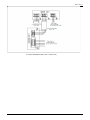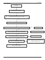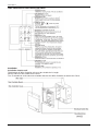
1
Service Manual
MODEL: CFT 35 INV-Ri
CFT 50 INV-Ri
CFT 70 INV-Ri
CFT 100 INV-Ri
CFT 140 INV-Ri
CFT 170INV-Ri
TLC-I-2011.1
Contents
Part 1 General Information……………………………………………..……………………………1
Part 2 Indoor Units…………………………………………………………………………………..8
Part 3 Outdoor Units……………………………………………………………………………….122
Part 4 Installation………………………………….…………………………….……..…………..165
Part 5 Control……………………………………………………..…………………………….…231
Part 6 Control Function…………………………………………..…………………………….…262
Manufacture reserves the right to discontinue, or change at any time, specifications or designs without
notices and without incurring obligations.
i
TLC-I-2011.1
Part 1
General Information
1. Model Names of Indoor/Outdoor Units .......................... 2
2. External Appearance ....................................................... 4
3. Nomenclature ................................................................... 6
4. Features ............................................................................ 7
1
TLC-I-2011.1
1. Model Names of Indoor/Outdoor Units
1.1 Indoor Units
Model name
DCT 35 INV-Si
DCT 50 INV-Si
Dimension
(W×H×D) (mm)
920×210×635
920×210×635
Net/Gross weight (kg)
Power supply
25/29
220~240V-1ph-50Hz
26/30
220~240V-1ph-50Hz
DCT 70 INV-Si
920×270×635
30/34
220~240V-1ph-50Hz
DCT 90 INV-Si
1140×270×775
41/46
220~240V-1ph-50Hz
DCT 100 INV-Si
1140×270×775
41/46
220~240V-1ph-50Hz
DCT 140 INV-Si
1200×300×865
49/55
220~240V-1ph-50Hz
DCT 170 INV-Si
1200×300×865
49/55
220~240V-1ph-50Hz
CFT 35 INV-Ri
990×203×660
27/33
220~240V-1ph-50Hz
CFT 50 INV-Ri
990×203×660
29/35
220~240V-1ph-50Hz
CFT 70 INV-Ri
990×203×660
29/35
220~240V-1ph-50Hz
CFT 90 INV-Ri
1280 ×203× 660
37/42
220~240V-1ph-50Hz
CFT 100 INV-Ri
1280 ×203× 660
37/42
220~240V-1ph-50Hz
CFT 140 INV-Ri
1670× 240× 680
52/59
220~240V-1ph-50Hz
CFT 170 INV-Ri
1670× 240× 680
52/59
220~240V-1ph-50Hz
CCT 50 INV-Si
CCT 70 INV-Si
840x230x840
28/34
220~240V-1ph-50Hz
840x230x840
29/36
220~240V-1ph-50Hz
CCT 90 INV-Si
840x300x840
36/41
220~240V-1ph-50Hz
CCT 100 INV-Si
840x300x840
36/41
220~240V-1ph-50Hz
CCT 140 INV-Si
840x300x840
36/41
220~240V-1ph-50Hz
CCT 170 INV-Si
840x300x840
42/50
220~240V-1ph-50Hz
CCT 301 INVi
580x254x580
18/27.5
220~240V-1ph-50Hz
CCT 501 INVi
580x254x580
21/28
220~240V-1ph-50Hz
1.2 Outdoor Units
Model name
CCT 301 INVo
CFT 35 INV-Ro
DCT 35 INV-So
CCT 501 INVo
CCT 50 INV-So
CFT 50 INV-Ro
DCT 50 INV-So
CCT 70 INV-So
CFT 70 INV-Ro
DCT 70 INV-So
CCT 100 INV-So-1
CFT 100 INV-Ro-1
DCT 100 INV-So-1
CCT 90 INV-So
CFT 90 INV-Ro
DCT 90 INV-So
CCT 100 INV-So
CFT 100 INV-Ro
DCT 100 INV-So
CCT 140 INV-So-1
CFT 140 INV-Ro-1
DCT 140 INV-So-1
Dimension
(W×H×D) (mm)
Net/Gross weight
(kg)
Power supply
761×593×279
39.5/42.5
220~240V-1ph-50Hz
842×695×324
59/63
220~240V-1ph-50Hz
895x862x313
73/76
220~240V-1 Ph-50Hz
940×1245×360
106/114
220~240V-1ph-50Hz
990×966×354
92/100
220~240V-1ph-50Hz
990×966×354
87/95
380V-3ph-50Hz
940×1245×360
106/114
220~240V-1ph-50Hz
2
TLC-I-2011.1
CCT 140 INV-So
CFT 140 INV-Ro
DCT 140 INV-So
CCT 170 INV-So
CFT 170 INV-Ro
DCT 170 INV-So
DHP 170 INV -Ro
940×1245×360
99/107
380V-3ph-50Hz
940×1245×360
115/121
380V-3ph-50Hz
940×1245×360
124/130
380~415V-3 Ph-50Hz
3
TLC-I-2011.1
2. External Appearance
2.1 Indoor units
Ceiling & Floor
4
TLC-I-2011.1
2.2 Outdoor unit
CCT 301 INVo, CFT 35 INV-Ro, DCT 35 INV-So
CCT 70 INV-So, CFT 70 INV-Ro, DCT 70 INV-So
CCT 501 INVo, CCT 50 INV-So,
CFT 50 INV-Ro, DCT 50 INV-So
CCT 90 INV-So, CFT 90 INV-Ro, DCT 90 INV-So
CCT 100 INV-So, CFT 100 INV-Ro, DCT 100 INV-So
CCT 100 INV-So-1, CFT 100 INV-Ro-1, DCT 100 INV-So-1
CCT 140 INV-So-1, CFT 140 INV-Ro-1, DCT 140 INV-So-1
CCT 140 INV-So, CFT 140 INV-Ro, DCT 140 INV-So
CCT 170 INV-So, CFT 170 INV-Ro, DCT 170 INV-So
DHP 170 INV -Ro
5
TLC-I-2011.1
3. Nomenclature
6
TLC-I-2011.1
4. Features
4.1 Universal outdoor unit design
Indoor unit with the same capacity can match with the same outdoor unit.
4.2 High efficiency and energy saving.
Thanks to the DC inverter technology and optimized piping system, the EER and COP of whole
series can easily reach A-class.
4.3 Low noise and low starting current.
Thanks to the DC inverter technology, the system can work with low noise, and very small starting
current.
4.4 Intelligent refrigerant adjustment technology.
Throttle part is made up of capillary and electronic expansion valve (EXV). The outdoor unit can
output the most accurate capacity in any condition.
4.5 Working in cooling mode under -15 .
Outdoor unit built-in with low ambient kit, it can control the outdoor unit’s fan and cooling can be
performed throughout the year for computer rooms, banquet halls, etc. Wide operation range
covers outdoor temperatures as low as -15 for cooling.
4.6 Indoor & outdoor unit’s power supply is separate.
4.7 All indoor units have network control function.
4.8 All indoor units have Auto-restart function.
7
TLC-I-2011.1
Part 2
Indoor Units
1. Ceiling and Floor Type…………………………………9
8
TLC-I-2011.1
Ceiling and Floor Type
1. Features ...................................................................................................
2. Specifications .........................................................................................
3. Dimensions .............................................................................................
4. Service Space ..........................................................................................
5. Wiring Diagrams ......................................................................................
6. Air Velocity and Temperature Distributions ..........................................
7. Capacity Tables .......................................................................................
8. Electric Characteristics ..........................................................................
9. Sound Levels ...........................................................................................
Accessories ...........................................................................................
9
TLC-I-2011.1
1. Features
1.1. New design, more modern and elegant appearance.
1.2. Convenient installation
--The ceiling type can be easily installed into a corner of the ceiling even if the ceiling is very narrow
--It is especially useful when installation of an air conditioner in the center of the ceiling is impossible due
to a structure such as one lighting
1.3. Two direction auto swing (vertical & horizontal) and wide angle air flow
--Air flow directional control minimizes the air resistance and produces wilder air flow to vertical direction.
--The range of horizontal air discharge is widened which secures wider air flow distribution to provide
more comfortable air circulation no matter where the unit is set up
1.4. Three level fan speed, more humanism design, meets different air-supply requirement.
1.5. Water proof by utilizing the absorbing plastic film on water collector
1.6. Easy operation. Auto-restart function, remote control and optional wire control method.
1.7. Low noise level plus compact size
--Shape of the blades has been improved to prevent noise caused by turbulence.
10
TLC-I-2011.1
2. Specifications
Capacity(Max.-Rated-Min.)
Model
name
Code
Power
supply
Model
name
Code
Power
supply
KW
Input(Max.-Rated-Min.)
KW
1.27-1.09-0.32
2.6-1.63-0.57
Current(Max.-Rated-Min.)
A
5.9-5.01-1.68
12.3-7.10-2.47
3.24
3.24
Indoor
Model
Outdoor
Cooling
EER
CFT 35 INV-Ri
CFT 50 INV-Ri
220044000060
220044100120
220~240V-1 Ph-50Hz
220~240V-1 Ph-50Hz
CFT 35 INV-Ro
CFT 50 INV-Ro
220075100071
220075200340
220~240V-1 Ph-50Hz
220~240V-1 Ph-50Hz
4.0-3.52-1.4
5.65-5.28-1.63
Capacity(Max.-Rated-Min.)
KW
4.75-4.0-1.4
6.15-5.86-1.45
Input(Max.-Rated-Min.)
KW
1.38-1.07-0.36
2.34-1.59-0.72
Current(Max.-Rated-Min.)
A
6.41-5.05-1.89
11.07-6.91-3.13
3.69
Max. input consumption
W
3.73
2250
Max. current
A
12
13.1
Type
DA108X1C-20FZ3
Rotary DC Inverter
C-6RVN93H0V
Rotary DC Inverter
Brand
MIDEA TOSHIBA
Shenyang SANYO
10918.4
19277.8
Heating
COP
Model
Compressor
Capacity
Btu/h
Input
W
855
1470
Rated current(RLA)
A
5.3
-
8.96
Thermal protector
Indoor fan
motor
Capacitor
uF
Refrigerant oil
ml
-
-
-
Model
ESTER OIL VG74 480ml
YSK25-6L
FV 50S, 350
Type
AC Motor
AC Motor
YSK55-4L
Input
w
33.4/31.1/29.5
125/105/85
Capacitor
uF
1.5uF/450V
2.5uF/450V
Speed(hi/mi/lo)
r/min
756/666/592
1310/1190/1040
3
3
b.Tube pitch(a)x row pitch(b)
mm
25.4×22
25.4 x 22
c.Fin spacing
mm
1.7
1.7
e.Tube outside dia.and type
mm
f.Coil length x height x width
mm
Hydrophilic aluminum
Ф9.53 Inner grooved copper
tube
804x254x66
Hydrophilic aluminum
Ф9.53 Inner grooved
copper tube
828x254x66
3
3
a.Number of rows
Indoor coil
2400
d.Fin type (code)
g.Number of circuits
3
Indoor air flow (Hi/Mi/Lo)
m /h
584/518/463
800/600/500
Sound level
dB(A)
39/36/33
43/41/38
Indoor unit
(sound pressure)
Dimension (W x H x D)
mm
990x203x660
990 x203 x660
Packing
mm
1089x296 x744
1089 x296 x744
27/33
29/35
Model
YDK24-6G
YDK53-6Y
Type
AC MOTOR
AC MOTOR
67/48
129/86
(W x H x D)
Net/Gross weight
Outdoor fan
motor
Input
kg
W
11
TLC-I-2011.1
Capacitor
uF
2.5/450V
3uF/450V
Speed
r/min
800/550
770/560
2
2
Number of rows
Outdoor coil
Tube pitch(a)x row pitch(b)
mm
25.4×22
22×19.05
Fin spacing
mm
1.4
1.4
Hydrophilic aluminium
Ф9.53 Inner grooved copper
tube
Hydrophilic aluminium
654×558.8×44
778×660×38.1
2
2
2500/1600
48/44
2570/2300
Fin type (code)
Tube outside dia.and type
mm
Coil length x height x width
mm
Number of circuits
3
Outdoor air flow(Hi/Low)
m /h
Sound level(sound pressure)(Hi/Low)
dB(A)
Outdoor unit
mm
761×593×279
842×695×324
Packing
mm
887×655×355
965x752x399
kg
39.5/42.5
R410A
59/63
(WxDxH)
Type
Charged volume
g
R410A
1400
1600
Capillary
Electronic expansion valve
& Capillary
MPa
4.2/2.0
4.2/2.0
Liquid side/ Gas side
mm
Ф6.4/Ф12.7
6.4/12.7
Max. refrigerant pipe length
Max. difference in level(Outdoor
is up)
Max. difference in level (Outdoor
is down)
Power wiring (Indoor)
m
10
25
Throttle type
Design pressure(Hi/Low)
Refrigerant
piping
51/46
Dimension(WxDxH)
Net/Gross weight
Refrigerant
7.94 Inner grooved
copper tube
m
6
m
12
5
9
mm
2
3×1.5
3 core x 1.0
mm
2
_
3 core x 2.5
mm
2
4×1.5
3-core shielded wire x0.5
Ф25
Ф25
R05/BGE (standard)
R05/BGE (standard)
Operation temp (Indoor)
17-30
17-30
Ambient temp (Outdoor)
Cooling 0~43 (*)
Heating -15~24
Cooling -15~43 (*)
Heating -15~24
Connection
wiring
Power wiring (Outdoor)
Signal wiring
Drainage water pipe dia. (Indoor)
Wireless remote controller (Indoor)
mm
(*) Optional Low Ambient Kit included. Cooling Operation Range: 7 to 43oC without it
12
TLC-I-2011.1
Capacity(Max.-Rated-Min.)
Model
name
Code
Power
supply
Model
name
Code
Power
supply
KW
Input(Max.-Rated-Min.)
KW
2.8-2.18-0.98
4.6-2.71-1.1
Current(Max.-Rated-Min.)
A
13.2-9.9-4.26
23-11.78-4.78
3.22
3.24
Indoor
Model
Outdoor
Cooling
EER
Heating
CFT 70 INV-Ri
CFT 90 INV-Ri
220044200240
220044300000
220~240V-1 Ph-50Hz
220~240V-1 Ph-50Hz
CFT 70 INV-Ro
CFT 90 INV-Ro
220075301070
220075401041
220~240V-1 Ph-50Hz
220~240V-1 Ph-50Hz
7.9-7.032-1.63
9.5-8.792-2.2
Capacity(Max.-Rated-Min.)
KW
8.6-8.2-1.75
11.0-9.965-2.6
Input(Max.-Rated-Min.)
KW
2.60-2.24-1.05
4.28-2.72-1.3
Current(Max.-Rated-Min.)
A
12.23-9.32-4.56
21.4-11.83-5.65
3.66
3.66
COP
Max. input consumption
W
3250
4600
Max. current
A
15.48
23
Model
ATL165SD-C9AU
TNB220FLBM1
Type
Rotary DC Inverter
Rotor DC Inverter
Brand
HITACHI
MITSUBISHI ELECTRIC
Compressor
Capacity
Btu/h
15525
24328
Input
W
1530
2200
Rated current(RLA)
A
10.4
9.7
-
-
Thermal protector
Indoor fan
motor
Capacitor
uF
-
-
Refrigerant oil
ml
68HES-H,880
MEL 56, 670
Model
YSK55-4L
YSK80-4A
Type
AC Motor
AC motor
Input
w
125/105/85
143/122/110
Capacitor
uF
2.5uF/450V
3.5uF/450V
Speed(hi/mi/lo)
r/min
1310/1190/1040
1310/1210/1115
3
3
a.Number of rows
Indoor coil
b.Tube pitch(a)x row pitch(b)
mm
25.4 x 22
25.4 x 22
c.Fin spacing
mm
1.7
1.7
Hydrophilic aluminum
Hydrophilic aluminum
e.Tube outside dia.and type
mm
Ф9.53 Inner groove tube
Ф9.53 Inner groove tube
f.Coil length x height x width
mm
828x254x66
1118 x 254 x 66
3
5
d.Fin type (code)
g.Number of circuits
3
Indoor air flow (Hi/Mi/Lo)
m /h
1000/900/700
1200/1000/800
Sound level
dB(A)
45/43/40
45/43/40
Indoor unit
(sound pressure)
Dimension (W x H x D)
mm
990 x203 x660
1280 x 203 x 660
Packing
mm
1089 x296 x744
1379 x 296 x 744
(W x H x D)
Net/Gross weight
Outdoor fan
motor
29/35
37/42
Model
YDK53-6Z(×1)
YDK250-6E
Type
AC MOTOR
AC MOTOR
141.5/92
307/194
Input
kg
W
13
TLC-I-2011.1
Capacitor
uF
Speed
r/min
3uF/450V
10uF±5% 450V
815/550
740/530
2
2
Number of rows
Outdoor coil
Tube pitch(a)x row pitch(b)
mm
25.4 x 22
25.4×22
Fin spacing
mm
1.5
1.7
Fin type (code)
Hydrophilic aluminum
Hydrophilic aluminum
Tube outside dia.and type
mm
Ф9.53 Inner grooved
copper tube
Ф9.53 Inner grooved
copper tube
Coil length x height x width
mm
758x813x44
876x914.4x44
2
4
Number of circuits
3
Outdoor air flow(Hi/Low)
m /h
3000/2850
5000/4800
Sound level(sound pressure)(Hi/Low)
dB(A)
55/48
55/50
Outdoor unit
Dimension(WxDxH)
mm
895x862x313
990×966×354
Packing
mm
1043x915x395
1120×1100×435
73/76
92/100
R410A
R410A
(WxDxH)
Net/Gross weight
Refrigerant
kg
Type
Charged volume
g
2300
3350
Electronic expansion valve
& Capillary
Electronic expansion valve
& Capillary
MPa
4.2/2.0
4.2/2.0
Liquid side/ Gas side
mm
9.5/15.9
9.5/15.9
Max. refrigerant pipe length
Max. difference in level(Outdoor is
up)
Max. difference in level (Outdoor
is down)
Power wiring (Indoor)
m
25
25
m
12
15
m
9
9
Throttle type
Design pressure(Hi/Low)
Refrigerant
piping
Connection
wiring
Power wiring (Outdoor)
Signal wiring
Drainage water pipe dia. (Indoor)
Wireless remote controller (Indoor)
Operation temp (Indoor)
Ambient temp (Outdoor)
mm
2
3 core x 1.0
3 core x 1.0
mm
2
3 core x 2.5
3 core x 2.5
mm
2
3-core shielded wire x0.5
3-core shielded wire x0.5
Ф25
Ф25
R05/BGE (standard)
R05/BGE (standard)
mm
17
30
Cooling -15~43(*)
Heating -15~24
17
30
Cooling -15~43(*)
Heating -15~24
(*) Optional Low Ambient Kit included. Cooling Operation Range without it: 7 to 43oC
14
TLC-I-2011.1
Capacity(Max.-Rated-Min.)
Model
name
Code
Power
supply
Model
name
Code
Power
supply
KW
13.2-10.551-3.0
13.2-10.55-3.0
Input(Max.-Rated-Min.)
KW
5.5-3.25-2.3
4.9-3.27-2.3
Current(Max.-Rated-Min.)
A
25-14.13-10
7.53-4.72-3.30
3.25
3.22
Indoor
Model
Outdoor
Cooling
EER
Heating
CFT 100 INV-Ri
CFT 100 INV-Ri
220044400310
220044400310
220~240V-1 Ph-50Hz
220~240V-1 Ph-50Hz
CFT 100 INV-Ro-1
CFT 100 INV-Ro
220075500651
220075500920
220~240V-1 Ph-50Hz
380V~3 Ph-50Hz
Capacity(Max.-Rated-Min.)
KW
14.0-11.72-3.7
14.0-11.72-3.7
Input(Max.-Rated-Min.)
KW
5.20-3.20-2.0
3.91-3.23-1.03
Current(Max.-Rated-Min.)
A
23.64-13.91-8.69
5.98-4.67-1.49
3.66
3.63
COP
Max. input consumption
W
5500
5000
Max. current
A
25
7.5
Model
TNB306FPGM
TNB306FPNM
Type
Rotor DC Inverter
Rotary DC Inverter
Brand
MITSUBISHI ELECTRIC
MITSUBISHI ELECTRIC
Compressor
Capacity
Btu/h
33642
33710
Input
W
3080
3010
Rated current(RLA)
A
13.5
9.3
-
-
Capacitor
uF
-
-
Refrigerant oil
ml
FV50S, 870
FV50S, 870
Model
YSK80-4A
YSK80-4A
Type
AC motor
AC motor
Thermal protector
Indoor fan
motor
Input
w
143/122/110
143/122/110
Capacitor
uF
3.5uF/450V
3.5uF/450V
Speed(hi/mi/lo)
r/min
1310/1210/1115
1310/1210/1115
3
3
a.Number of rows
Indoor coil
b.Tube pitch(a)x row pitch(b)
mm
25.4 x 22
25.4 x 22
c.Fin spacing
mm
1.7
1.7
Hydrophilic aluminum
Hydrophilic aluminum
d.Fin type (code)
e.Tube outside dia.and type
mm
Ф9.53 Inner groove tube
Ф9.53 Inner groove tube
f.Coil length x height x width
mm
1118 x 254 x 66
1118 x 254 x 66
5
5
g.Number of circuits
3
Indoor air flow (Hi/Mi/Lo)
m /h
1400/1200/1000
1400/1200/1000
Sound level
dB(A)
45/43/40
45/43/40
Indoor unit
(sound pressure)
Dimension (W x H x D)
mm
1280 x 203 x 660
1280 x 203 x 660
Packing
mm
1379 x 296 x 744
1379 x 296 x 744
37/42
37/42
(YDK100-6A)×2
YDK250-6E(×1)
(W x H x D)
Net/Gross weight
kg
Model
Outdoor fan
motor
Type
AC MOTOR
AC Motor
Input
W
(185/120)×2
307/194
Capacitor
uF
(3.5uF/450V)×2
10uF±5% 450V
15
TLC-I-2011.1
Speed
r/min
(860/610)×2
740/530
2
2
Number of rows
Outdoor coil
Tube pitch(a)x row pitch(b)
mm
25.4×22
25.4×22
Fin spacing
mm
1.5
1.7
Hydrophilic aluminum
Hydrophilic aluminum
Fin type (code)
Tube outside dia.and type
mm
Ф9.53 Inner grooved
copper tube
Ф9.53 Inner grooved
copper tube
Coil length x height x width
mm
887×1220×44
876×914.4×44
8
4
6000/5800
5000/4800
Number of circuits
3
Outdoor air flow(Hi/Low)
m /h
Sound level(sound pressure)(Hi/Low)
dB(A)
Outdoor unit
57/52
55/50
Dimension(WxDxH)
mm
940×1245×360
990×966×354
Packing
mm
1058×1380×438
1120×1100×435
106/114
87/95
R410A
R410A
4100
2900
Electronic expansion valve
& Capillary
Electronic expansion valve
& Capillary
MPa
4.2/2.0
4.2/2.0
Liquid side/ Gas side
mm
9.5/15.9
9.5/15.9
Max. refrigerant pipe length
Max. difference in level(Outdoor is
up)
Max. difference in level (Outdoor
is down)
Power wiring (Indoor)
m
30
30
m
20
20
m
12
12
(WxDxH)
Net/Gross weight
Refrigerant
kg
Type
Charged volume
g
Throttle type
Design pressure(Hi/Low)
Refrigerant
piping
Connection
wiring
Power wiring (Outdoor)
Signal wiring
Drainage water pipe dia. (Indoor)
Wireless remote controller (Indoor)
Operation temp (Indoor)
Ambient temp (Outdoor)
mm
2
3core x 1.0
3×1.0
mm
2
3 core x 2.5
5×2.5
mm
2
3-core shielded wire x0.5
mm
3-core shield wire
3×0.5
Ф25
Ф25
R05/BGE (standard)
R05/BGE (standard)
17
30
Cooling -15~43(*)
Heating -15~24
17
30
Cooling -15~43(*)
Heating -15~24
(*) Optional Low Ambient Kit included. Cooling Operation Range without it: 7 to 43oC
16
TLC-I-2011.1
Capacity(Max.-Rated-Min.)
Model
name
Code
Power
supply
Model
name
Code
Power
supply
KW
Input(Max.-Rated-Min.)
KW
Current(Max.-Rated-Min.)
A
Indoor
Model
Outdoor
Cooling
EER
Heating
CFT 140 INV-Ri
CFT 140 INV-Ri
CFT 170 INV-Ri
220044600230
220~240V-1
Ph-50Hz
220044600230
220~240V-1
Ph-50Hz
220044700210
220~240V-1
Ph-50Hz
CFT 140 INV-Ro-1
CFT 140 INV-Ro
CFT 170 INV-Ro
220075700341
220~240V-1
Ph-50Hz
15.6-14.06-3.6
220075700690
220075800161
380V~3 Ph-50Hz
380V~-3 Ph-50Hz
15.6-14.06-3.4
19.0-17.58-4.25
6.0-4.32-2.5
5.95-4.33-2.5
7.5-5.46-3.0
28-18.78-10.8
8.5-6.27-3.60
11.5-8.3-4.3
3.26
3.25
3.22
Capacity(Max.-Rated-Min.)
KW
16.5-15.24-4.2
16.5-15.53-4.2
21.38-20.22-4.8
Input(Max.-Rated-Min.)
KW
5.59-4.13-2.3
5.51-4.29-1.45
6.28-5.6-1.65
Current(Max.-Rated-Min.)
A
26.07-17.96-10
8.48-6.19-2.08
9.63-7.06-2.37
3.69
3.62
3.61
COP
Max. input consumption
W
6000
5500
7500
Max. current
A
28
7.8
11.5
Model
TNB306FPGM
TNB306FPNM
ANB42FBEMT
Type
Rotor DC Inverter
MITSUBISHI
ELECTRIC
33642
Rotary DC Inverter
MITSUBISHI
ELECTRIC
33710
Scroll DC Inverter
Brand
Compressor
Capacity
Btu/h
Input
W
3080
3010
4160
Rated current(RLA)
A
13.5
9.3
15.2
-
-
-
Thermal protector
Indoor fan
motor
47440
Capacitor
uF
-
-
-
Refrigerant oil
ml
FV50S, 870
FV50S, 870
MEL 56, 1700
Model
(YSK59-4D) x 2
(YSK59-4D) x 2
(YSK59-4D) x 2
Type
AC motor
AC motor
AC motor
Input
w
(89.5/81.5/77.5) x2
(89.5/81.5/77.5) x2
(89.5/81.5/77.5) x2
Capacitor
uF
2.5uF/450V) x2
2.5uF/450V) x2
(2.5uF/450V) x2
Speed(hi/mi/lo)
r/min
(1170/1070/995) x2
(1170/1070/995) x2
(1170/1070/995) x2
3
3
3
a.Number of rows
Indoor coil
SIAM
b.Tube pitch(a)x row pitch(b)
mm
25.4 x 22
25.4 x 22
25.4 x 22
c.Fin spacing
mm
1.7
Hydrophilic
aluminum
Ф9.53 Inner groove
tube
1384 x 254 x 66
1.7
Hydrophilic
aluminum
Ф9.53 Inner groove
tube
1384 x 254 x 66
1.7
Hydrophilic
aluminum
Ф9.53 Inner groove
tube
1384 x 254 x 66
5
5
5
d.Fin type (code)
e.Tube outside dia.and type
mm
f.Coil length x height x width
mm
g.Number of circuits
3
Indoor air flow (Hi/Mi/Lo)
m /h
2000/1800/1600
2000/1800/1600
2000/1800/1600
Sound level
dB(A)
47/46/44
47/46/44
47/46/44
Indoor unit
(sound pressure)
Dimension (W x H x D)
mm
1670 x 240 x 680
1670 x 240 x 680
1670 x 240 x 680
Packing
mm
1764 x 329 x 760
1764 x 329 x 760
1764 x 329 x 760
52/59
52/59
52/59
Model
(YDK100-6A)×2
YDK100-6A(×2)
(YDK100-6A)×2
Type
AC MOTOR
AC Motor
AC MOTOR
(185/120)×2
185/120
(185/120)×2
(W x H x D)
Net/Gross weight
Outdoor fan
motor
Input
kg
W
17
TLC-I-2011.1
Capacitor
uF
Speed
r/min
Number of rows
Outdoor coil
860/610
(860/610)×2
2
2
2
25.4×22
25.4 x 22
Fin spacing
mm
1.5
Hydrophilic
aluminum
Ф9.53 Inner
grooved copper
tube
887×1220×44
1.8
Hydrophilic
aluminum
Ф9.53 Inner
grooved copper
tube
887×1220×44
1.8
Hydrophilic
aluminum
Ф9.53 Inner
grooved copper
tube
887×1220×44
8
8
4
6000/5800
6000/5800
6000/5800
Fin type (code)
Tube outside dia.and type
mm
Coil length x height x width
mm
3
Sound level(sound pressure)(Hi/Low)
dB(A)
59/54
59/54
59/54
Dimension(WxDxH)
mm
940×1245×360
940×1245×360
940×1245×360
Packing
mm
1058×1380×438
1058×1380×438
1058×1380×438
106/114
99/107
115/121
R410A
R410A
R410A
3600
3850
Electronic expansion
valve & Capillary
Electronic expansion
valve & Capillary
(WxDxH)
Net/Gross weight
kg
Type
Charged volume
g
MPa
4450
Electronic
expansion valve &
Capillary
4.2/2.0
4.2/2.0
4.2/2.0
Liquid side/ Gas side
mm
9.5/15.9
9.5/15.9
9.5/15.9
Max. refrigerant pipe length
Max. difference in
level(Outdoor is up)
Max. difference in level
(Outdoor is down)
Power wiring (Indoor)
m
50
50
50
m
25
30
30
m
20
20
20
Throttle type
Design pressure(Hi/Low)
Connection
wiring
(860/610)×2
25.4×22
m /h
Refrigerant
piping
(3.5uF/450V)×2
mm
Outdoor air flow(Hi/Low)
Refrigerant
3.5uF/450V
Tube pitch(a)x row pitch(b)
Number of circuits
Outdoor unit
(3.5uF/450V)×2
Power wiring (Outdoor)
Signal wiring
Drainage water pipe dia. (Indoor)
Wireless remote controller (Indoor)
Operation temp (Indoor)
Ambient temp (Outdoor)
mm
2
3 core x 1.0
3×1.0
3 core x 1.0
mm
2
mm
2
3 core x 2.5
3-core shielded
wire x0.5
Ф25
R05/BGE
(standard)
17 30
5×2.5
3-core shield wire
3×0.5
Ф25
5 core×2.5
3-core shielded wire
x0.5
Ф25
R05/BGE (standard)
R05/BGE (standard)
mm
Cooling -15~43(*)
Heating -15~24
17
30
Cooling -15~43(*)
Heating -15~24
17
30
Cooling -15~43(*)
Heating -15~24
(*) Optional Low Ambient Kit included. Cooling Operation Range without it: 7 to 43oC
18
TLC-I-2011.1
3. Dimensions
20
TLC-I-2011.1
A
B
C
D
E
F
G
H
12000-24000Btu/h
Capacity(Btu/h)
990
660
206
505
506
907
200
203
30000-36000Btu/h
1280
660
206
795
506
1195
200
203
48000-60000Btu/h
1670
680
244
1070
450
1542
200
240
4. Service
Space
21
TLC-I-2011.1
5. Wiring
Diagrams
CFT 35 INV-Ri
22
TLC-I-2011.1
CFT 50 INV-Ri, CFT 70 INV-Ri
CFT 90 INV-Ri, CFT 100 INV-Ri, CFT 140 INV-Ri, CFT 170 INV-Ri
23
TLC-I-2011.1
6. Air Velocity and Temperature
Discharge angle 60e
e (CEILING)
Distributions
Airflow velocity
Condenser
Evaporator
Electronic
Condenser temp. sensor expansion valve
High pressure switch
Evaporator temp. sensor
T2
T3
Filter
Capillary
Filter
T1
Room temp. sensor
T5
Discharge temp. sensor
Oil separator
T4
Ambient temp. sensor
4-way valve
Compressor
Filter
Oil return
Capillary
Filter
Low pressure liquid
Low pressure accumulator
switch
Outdoor unit
Indoor unit
24
TLC-I-2011.1
Discharge angle 60e
e(FLOOR)
Airflow velocity
Temperature
25
TLC-I-2011.1
7. Capacity
Tables
CFT 35 INV-Ri
Cooling
Indoor temperature(°C WB)
Outdoor
temperature(°C
DB)
14.00
16.00
18.00
19.00
20.00
22.00
24.00
TC
PI
TC
PI
TC
PI
TC
PI
TC
PI
TC
PI
TC
PI
kW
kW
kW
kW
kW
kW
kW
kW
kW
kW
kW
kW
kW
kW
10.00
2.22
0.33
2.72
0.41
3.22
0.49
3.52
0.53
3.68
0.58
3.76
0.58
3.83
0.58
12.00
2.22
0.34
2.72
0.42
3.22
0.50
3.52
0.54
3.68
0.59
3.76
0.59
3.83
0.59
14.00
2.22
0.34
2.72
0.43
3.22
0.51
3.52
0.55
3.68
0.60
3.76
0.60
3.83
0.61
16.00
2.22
0.35
2.72
0.43
3.22
0.52
3.52
0.56
3.68
0.61
3.76
0.61
3.83
0.62
18.00
2.22
0.35
2.72
0.44
3.22
0.53
3.52
0.57
3.68
0.62
3.76
0.62
3.83
0.63
19.00
2.22
0.36
2.72
0.45
3.22
0.54
3.52
0.58
3.68
0.63
3.76
0.63
3.83
0.64
21.00
2.22
0.39
2.72
0.48
3.22
0.58
3.52
0.63
3.68
0.68
3.76
0.68
3.83
0.68
23.00
2.22
0.41
2.72
0.52
3.22
0.62
3.52
0.67
3.68
0.72
3.76
0.73
3.83
0.73
25.00
2.22
0.44
2.72
0.55
3.22
0.66
3.52
0.72
3.68
0.77
3.76
0.78
3.83
0.78
27.00
2.22
0.47
2.72
0.59
3.22
0.71
3.52
0.77
3.68
0.83
3.76
0.83
3.83
0.84
29.00
2.22
0.51
2.72
0.63
3.22
0.76
3.52
0.82
3.68
0.88
3.76
0.89
3.83
0.89
31.00
2.22
0.54
2.72
0.67
3.22
0.81
3.52
0.87
3.68
0.94
3.76
0.94
3.83
0.95
33.00
2.22
0.58
2.72
0.72
3.22
0.86
3.52
0.97
3.68
1.00
3.76
1.01
3.83
1.02
35.00
2.22
0.61
2.72
0.76
3.22
0.91
3.52
1.09
3.68
1.07
3.76
1.07
3.83
1.08
37.00
2.22
0.65
2.72
0.81
3.22
0.97
3.52
1.11
3.68
1.14
3.76
1.14
3.83
1.15
39.00
2.22
0.65
2.72
0.81
3.22
0.98
3.52
1.13
3.68
1.14
3.76
1.14
3.83
1.15
41.00
2.22
0.66
2.72
0.82
3.22
0.98
3.52
1.14
3.68
1.15
3.76
1.15
3.83
1.16
43.00
2.22
0.66
2.72
0.82
3.22
0.98
3.52
1.14
3.68
1.15
3.76
1.15
3.83
1.17
Heating
Indoor temperature(°C DB)
Outdoor air temp.
°C DB
-14.7
-12.6
-10.5
-9.5
-8.5
-7
-5
-3
0
3
5
7
9
11
13
15
°C WB
-15
-13
-11
-10
-9.1
-7.6
-5.6
-3.7
-0.7
2.2
4.1
6
7.9
9.8
11.8
13.7
16
TC
kW
2.54
2.68
2.82
2.89
2.96
3.06
3.19
3.33
3.53
3.73
3.87
4.00
4.00
4.00
4.00
4.00
18
PI
kW
0.88
0.89
0.91
0.91
0.92
0.93
0.94
0.96
0.98
1.00
1.01
1.03
0.99
0.96
0.92
0.89
TC
kW
2.54
2.68
2.82
2.89
2.96
3.06
3.19
3.33
3.53
3.73
3.87
4.00
4.00
4.00
4.00
4.00
20
PI
kW
0.90
0.91
0.92
0.93
0.94
0.95
0.96
0.98
1.00
1.02
1.03
1.05
1.01
0.98
0.94
0.91
TC
kW
2.54
2.68
2.82
2.89
2.96
3.06
3.19
3.33
3.53
3.73
3.87
4.00
4.00
4.00
4.00
4.00
21
PI
kW
0.91
0.93
0.94
0.95
0.96
0.97
0.98
1.00
1.02
1.04
1.06
1.07
1.03
1.00
0.96
0.93
TC
kW
2.44
2.57
2.71
2.77
2.84
2.94
3.07
3.20
3.39
3.58
3.71
3.84
3.84
3.84
3.84
3.84
22
PI
kW
0.87
0.89
0.90
0.91
0.92
0.93
0.94
0.95
0.97
1.00
1.01
1.02
0.99
0.95
0.92
0.89
TC
kW
2.34
2.47
2.60
2.66
2.72
2.82
2.94
3.06
3.25
3.43
3.56
3.68
3.68
3.68
3.68
3.68
24
PI
kW
0.83
0.85
0.86
0.87
0.87
0.88
0.90
0.91
0.93
0.95
0.96
0.98
0.94
0.91
0.88
0.85
TC
kW
2.14
2.26
2.37
2.43
2.49
2.57
2.69
2.80
2.97
3.14
3.25
3.37
3.37
3.37
3.37
3.37
PI
kW
0.75
0.77
0.78
0.78
0.79
0.80
0.81
0.82
0.84
0.86
0.87
0.88
0.85
0.82
0.79
0.76
26
TLC-I-2011.1
CFT 50 INV-Ri
Cooling
Indoor temperature(°C WB)
Outdoor
temperature(°C
DB)
TC
kW
kW
kW
kW
kW
kW
kW
kW
kW
kW
kW
kW
kW
kW
10.00
3.65
0.54
4.31
0.68
4.97
0.81
5.28
0.88
5.57
0.95
5.69
0.95
5.82
0.96
12.00
3.65
0.55
4.31
0.69
4.97
0.83
5.28
0.90
5.57
0.97
5.69
0.97
5.82
0.98
14.00
3.65
0.56
4.31
0.70
4.97
0.84
5.28
0.91
5.57
0.98
5.69
0.99
5.82
1.00
16.00
3.65
0.57
4.31
0.72
4.97
0.86
5.28
0.93
5.57
1.00
5.69
1.00
5.82
1.01
18.00
3.65
0.58
4.31
0.73
4.97
0.87
5.28
0.95
5.57
1.02
5.69
1.02
5.82
1.03
19.00
3.65
0.59
4.31
0.74
4.97
0.89
5.28
0.96
5.57
1.04
5.69
1.04
5.82
1.05
21.00
3.65
0.64
4.31
0.79
4.97
0.95
5.28
1.03
5.57
1.11
5.69
1.11
5.82
1.13
23.00
3.65
0.68
4.31
0.85
4.97
1.02
5.28
1.10
5.57
1.19
5.69
1.19
5.82
1.21
25.00
3.65
0.73
4.31
0.91
4.97
1.09
5.28
1.18
5.57
1.27
5.69
1.28
5.82
1.29
27.00
3.65
0.78
4.31
0.97
4.97
1.16
5.28
1.26
5.57
1.36
5.69
1.37
5.82
1.38
29.00
3.65
0.83
4.31
1.04
4.97
1.24
5.28
1.35
5.57
1.45
5.69
1.46
5.82
1.47
31.00
3.65
0.89
4.31
1.11
4.97
1.33
5.28
1.44
5.57
1.55
5.69
1.56
5.82
1.57
33.00
3.65
0.95
4.31
1.18
4.97
1.41
5.28
1.53
5.57
1.65
5.69
1.66
5.82
1.67
35.00
3.65
1.01
4.31
1.26
4.97
1.50
5.28
1.63
5.57
1.76
5.69
1.76
5.82
1.78
37.00
3.65
1.07
4.31
1.33
4.97
1.60
5.28
1.73
5.57
1.87
5.69
1.87
5.82
1.89
39.00
3.65
1.08
4.31
1.34
4.97
1.61
5.28
1.74
5.57
1.88
5.69
1.88
5.82
1.90
41.00
3.65
1.08
4.31
1.35
4.97
1.61
5.28
1.75
5.57
1.89
5.69
1.89
5.82
1.91
43.00
3.65
1.09
4.31
1.35
4.97
1.62
5.28
1.76
5.57
1.89
5.69
1.90
5.82
1.92
14.00
16.00
PI
TC
18.00
PI
TC
19.00
PI
TC
20.00
PI
TC
22.00
PI
TC
24.00
PI
TC
PI
Heating
Indoor temperature(°C DB)
Outdoor air temp.
°C DB
-14.7
-12.6
-10.5
-9.5
-8.5
-7
-5
-3
0
3
5
7
9
11
13
15
°C WB
-15
-13
-11
-10
-9.1
-7.6
-5.6
-3.7
-0.7
2.2
4.1
6
7.9
9.8
11.8
13.7
16
TC
kW
3.72
3.93
4.13
4.23
4.33
4.48
4.68
4.87
5.17
5.47
5.66
5.86
5.86
5.86
5.86
5.86
18
PI
kW
1.30
1.32
1.35
1.36
1.37
1.38
1.40
1.42
1.45
1.48
1.50
1.52
1.47
1.42
1.37
1.32
TC
kW
3.72
3.93
4.13
4.23
4.33
4.48
4.68
4.87
5.17
5.47
5.66
5.86
5.86
5.86
5.86
5.86
20
PI
kW
1.33
1.35
1.37
1.38
1.40
1.41
1.43
1.45
1.48
1.52
1.54
1.56
1.51
1.45
1.40
1.35
TC
kW
3.72
3.93
4.13
4.23
4.33
4.48
4.68
4.87
5.17
5.47
5.66
5.86
5.86
5.86
5.86
5.86
21
PI
kW
1.36
1.38
1.40
1.41
1.42
1.44
1.46
1.48
1.52
1.55
1.57
1.59
1.54
1.48
1.43
1.38
TC
kW
3.57
3.77
3.97
4.07
4.16
4.30
4.49
4.68
4.96
5.25
5.44
5.63
5.63
5.63
5.63
5.63
22
PI
kW
1.30
1.32
1.34
1.35
1.36
1.38
1.40
1.42
1.45
1.48
1.50
1.52
1.47
1.42
1.37
1.32
TC
kW
3.43
3.62
3.81
3.90
3.99
4.12
4.31
4.49
4.76
5.03
5.21
5.39
5.39
5.39
5.39
5.39
24
PI
kW
1.24
1.26
1.28
1.29
1.30
1.31
1.33
1.35
1.38
1.41
1.43
1.45
1.40
1.35
1.30
1.26
TC
kW
3.13
3.30
3.48
3.56
3.64
3.77
3.93
4.10
4.35
4.60
4.76
4.93
4.93
4.93
4.93
4.93
PI
kW
1.12
1.14
1.16
1.17
1.17
1.19
1.21
1.22
1.25
1.28
1.29
1.31
1.27
1.22
1.18
1.14
27
TLC-I-2011.1
CFT 70 INV-Ri
Cooling
Indoor temperature(°C WB)
Outdoor
temperature(°C
DB)
TC
kW
kW
kW
kW
kW
kW
kW
kW
kW
kW
kW
kW
kW
kW
10.00
4.87
0.73
5.75
0.91
6.63
1.09
7.03
1.18
7.44
1.27
7.60
1.27
7.76
1.29
12.00
4.87
0.74
5.75
0.92
6.63
1.11
7.03
1.20
7.44
1.29
7.60
1.30
7.76
1.31
14.00
4.87
0.75
5.75
0.94
6.63
1.13
7.03
1.22
7.44
1.32
7.60
1.32
7.76
1.33
16.00
4.87
0.77
5.75
0.96
6.63
1.15
7.03
1.24
7.44
1.34
7.60
1.34
7.76
1.36
18.00
4.87
0.78
5.75
0.97
6.63
1.17
7.03
1.26
7.44
1.36
7.60
1.37
7.76
1.38
19.00
4.87
0.79
5.75
0.99
6.63
1.19
7.03
1.29
7.44
1.39
7.60
1.39
7.76
1.40
21.00
4.87
0.85
5.75
1.06
6.63
1.27
7.03
1.38
7.44
1.49
7.60
1.49
7.76
1.51
23.00
4.87
0.91
5.75
1.14
6.63
1.36
7.03
1.48
7.44
1.59
7.60
1.60
7.76
1.61
25.00
4.87
0.98
5.75
1.22
6.63
1.46
7.03
1.58
7.44
1.70
7.60
1.71
7.76
1.73
27.00
4.87
1.04
5.75
1.30
6.63
1.56
7.03
1.69
7.44
1.82
7.60
1.83
7.76
1.84
29.00
4.87
1.11
5.75
1.39
6.63
1.66
7.03
1.80
7.44
1.94
7.60
1.95
7.76
1.97
31.00
4.87
1.19
5.75
1.48
6.63
1.77
7.03
1.92
7.44
2.07
7.60
2.08
7.76
2.10
33.00
4.87
1.27
5.75
1.58
6.63
1.89
7.03
2.05
7.44
2.21
7.60
2.22
7.76
2.24
35.00
4.87
1.35
5.75
1.68
6.63
2.01
7.03
2.18
7.44
2.35
7.60
2.36
7.76
2.38
37.00
4.87
1.43
5.75
1.79
6.63
2.14
7.03
2.32
7.44
2.50
7.60
2.51
7.76
2.53
39.00
4.87
1.44
5.75
1.79
6.63
2.15
7.03
2.33
7.44
2.51
7.60
2.52
7.76
2.54
41.00
4.87
1.45
5.75
1.80
6.63
2.16
7.03
2.34
7.44
2.52
7.60
2.53
7.76
2.55
43.00
4.87
1.45
5.75
1.81
6.63
2.17
7.03
2.35
7.44
2.53
7.60
2.54
7.76
2.57
14.00
16.00
PI
TC
18.00
PI
TC
19.00
PI
TC
20.00
PI
TC
22.00
PI
TC
24.00
PI
TC
PI
Heating
Indoor temperature(°C DB)
Outdoor air temp.
°C DB
-14.7
-12.6
-10.5
-9.5
-8.5
-7
-5
-3
0
3
5
7
9
11
13
15
°C WB
-15
-13
-11
-10
-9.1
-7.6
-5.6
-3.7
-0.7
2.2
4.1
6
7.9
9.8
11.8
13.7
16
TC
kW
4.93
5.20
5.48
5.61
5.74
5.94
6.20
6.46
6.90
7.37
7.83
8.21
8.21
8.21
8.21
8.21
18
PI
kW
1.74
1.77
1.79
1.81
1.82
1.84
1.87
1.90
1.94
1.98
2.01
2.03
1.96
1.90
1.83
1.76
TC
kW
4.93
5.20
5.48
5.61
5.74
5.94
6.20
6.46
6.90
7.37
7.83
8.21
8.21
8.21
8.21
8.21
20
PI
kW
1.77
1.80
1.83
1.85
1.86
1.88
1.91
1.94
1.98
2.02
2.05
2.12
2.01
1.94
1.87
1.80
TC
kW
4.93
5.20
5.48
5.61
5.74
5.94
6.20
6.46
6.90
7.37
7.83
8.21
8.21
8.21
8.21
8.21
21
PI
kW
1.81
1.84
1.87
1.88
1.90
1.92
1.95
1.98
2.02
2.06
2.13
2.24
2.14
1.98
1.91
1.84
TC
kW
4.73
5.00
5.26
5.39
5.51
5.70
5.95
6.20
6.78
6.96
7.41
7.86
7.86
7.86
7.86
7.86
22
PI
kW
1.73
1.76
1.79
1.80
1.82
1.84
1.86
1.89
1.93
1.97
2.00
2.09
1.96
1.89
1.82
1.75
TC
kW
4.54
4.79
5.04
5.16
5.28
5.46
5.71
5.95
6.41
6.67
6.98
7.35
7.35
7.35
7.35
7.35
24
PI
kW
1.65
1.68
1.71
1.72
1.73
1.75
1.78
1.80
1.84
1.88
1.91
1.93
1.87
1.80
1.74
1.67
TC
kW
4.15
4.38
4.61
4.72
4.83
4.99
5.21
5.43
5.76
6.09
6.31
6.63
6.63
6.63
6.63
6.63
PI
kW
1.49
1.52
1.54
1.55
1.57
1.58
1.61
1.63
1.67
1.70
1.72
1.75
1.69
1.63
1.57
1.51
28
TLC-I-2011.1
CFT 100 INV-Ri (3 Phase)
Cooling
Indoor temperature(°C WB)
Outdoor
temperature(°C
DB)
TC
kW
kW
kW
kW
kW
kW
kW
kW
kW
kW
kW
kW
kW
kW
10.00
7.27
1.09
8.58
1.36
9.90
1.62
10.55
1.76
11.10
1.90
11.35
1.90
11.59
1.92
12.00
7.27
1.11
8.58
1.38
9.90
1.65
10.55
1.79
11.10
1.93
11.35
1.94
11.59
1.96
14.00
7.27
1.13
8.58
1.41
9.90
1.68
10.55
1.83
11.10
1.97
11.35
1.97
11.59
1.99
16.00
7.27
1.15
8.58
1.43
9.90
1.71
10.55
1.86
11.10
2.00
11.35
2.01
11.59
2.03
18.00
7.27
1.17
8.58
1.46
9.90
1.74
10.55
1.89
11.10
2.04
11.35
2.04
11.59
2.06
19.00
7.27
1.19
8.58
1.48
9.90
1.77
10.55
1.92
11.10
2.07
11.35
2.08
11.59
2.10
21.00
7.27
1.27
8.58
1.59
9.90
1.90
10.55
2.06
11.10
2.22
11.35
2.23
11.59
2.25
23.00
7.27
1.36
8.58
1.70
9.90
2.04
10.55
2.21
11.10
2.38
11.35
2.39
11.59
2.41
25.00
7.27
1.46
8.58
1.82
9.90
2.18
10.55
2.36
11.10
2.55
11.35
2.56
11.59
2.58
27.00
7.27
1.56
8.58
1.95
9.90
2.33
10.55
2.53
11.10
2.72
11.35
2.73
11.59
2.76
29.00
7.27
1.67
8.58
2.08
9.90
2.49
10.55
2.70
11.10
2.91
11.35
2.92
11.59
2.95
31.00
7.27
1.78
8.58
2.22
9.90
2.65
10.55
2.88
11.10
3.10
11.35
3.11
11.59
3.14
33.00
7.27
1.89
8.58
2.36
9.90
2.83
10.55
3.06
11.10
3.30
11.35
3.31
11.59
3.35
35.00
7.27
2.01
8.58
2.51
9.90
3.01
10.55
3.27
11.10
3.51
11.35
3.53
11.59
3.56
37.00
7.27
2.14
8.58
2.67
9.90
3.20
10.55
3.47
11.10
3.74
11.35
3.75
11.59
3.79
39.00
7.27
2.15
8.58
2.68
9.90
3.21
10.55
3.48
11.10
3.75
11.35
3.77
11.59
3.80
41.00
7.27
2.16
8.58
2.69
9.90
3.23
10.55
3.50
11.10
3.77
11.35
3.78
11.59
3.82
43.00
7.27
2.17
8.58
2.71
9.90
3.24
10.55
3.51
11.10
3.79
11.35
3.80
11.59
3.84
14.00
16.00
PI
TC
18.00
PI
TC
19.00
PI
TC
20.00
PI
TC
22.00
PI
TC
24.00
PI
TC
PI
Heating
Indoor temperature(°C DB)
Outdoor air
temp.
°C DB
-14.7
-12.6
-10.5
-9.5
-8.5
-7
-5
-3
0
3
5
7
9
11
13
15
°C WB
-15
-13
-11
-10
-9.1
-7.6
-5.6
-3.7
-0.7
2.2
4.1
6
7.9
9.8
11.8
13.7
16
TC
kW
7.00
7.39
7.78
7.96
8.15
8.43
8.80
9.17
9.73
10.28
10.85
11.72
11.72
11.72
11.72
11.72
18
PI
kW
2.48
2.52
2.56
2.58
2.60
2.63
2.67
2.71
2.77
2.83
2.87
2.91
2.81
2.71
2.61
2.52
TC
kW
7.00
7.39
7.78
7.96
8.15
8.43
8.80
9.17
9.73
10.28
10.85
11.72
11.72
11.72
11.72
11.72
20
PI
kW
2.54
2.58
2.62
2.64
2.66
2.69
2.73
2.77
2.83
2.89
2.93
2.97
2.87
2.77
2.67
2.57
TC
kW
7.00
7.39
7.78
7.96
8.15
8.43
8.80
9.17
9.73
10.28
10.85
11.72
11.72
11.72
11.72
11.72
21
PI
kW
2.59
2.63
2.67
2.69
2.71
2.74
2.79
2.83
2.89
2.95
2.99
3.23
3.03
2.83
2.72
2.62
TC
kW
6.72
7.10
7.47
7.65
7.83
8.09
8.45
8.81
9.34
9.88
10.23
10.59
10.59
10.59
10.59
10.59
22
PI
kW
2.47
2.52
2.56
2.58
2.60
2.62
2.66
2.70
2.76
2.82
2.86
2.90
2.80
2.70
2.61
2.51
TC
kW
6.44
6.80
7.16
7.33
7.50
7.76
8.10
8.44
8.95
9.47
9.81
10.15
10.15
10.15
10.15
10.15
24
PI
kW
2.36
2.40
2.44
2.46
2.48
2.50
2.54
2.58
2.63
2.69
2.73
2.76
2.67
2.58
2.49
2.39
TC
kW
5.89
6.22
6.54
6.70
6.86
7.09
7.40
7.71
8.18
8.65
8.96
9.28
9.28
9.28
9.28
9.28
PI
kW
2.13
2.17
2.21
2.22
2.24
2.26
2.30
2.33
2.38
2.43
2.47
2.50
2.42
2.33
2.25
2.16
31
TLC-I-2011.1
CFT 140 INV-Ri (3 Phase)
Cooling
Indoor temperature(°C WB)
Outdoor
temperature(°C
DB)
TC
kW
kW
kW
kW
kW
kW
kW
kW
kW
kW
kW
kW
kW
kW
10.00
9.70
1.45
11.45
1.80
13.20
2.16
14.06
2.34
14.81
2.52
15.13
2.53
15.45
2.55
12.00
9.70
1.47
11.45
1.83
13.20
2.20
14.06
2.38
14.81
2.57
15.13
2.58
15.45
2.60
14.00
9.70
1.50
11.45
1.87
13.20
2.24
14.06
2.42
14.81
2.61
15.13
2.62
15.45
2.65
16.00
9.70
1.53
11.45
1.90
13.20
2.28
14.06
2.47
14.81
2.66
15.13
2.67
15.45
2.69
18.00
9.70
1.55
11.45
1.93
13.20
2.32
14.06
2.51
14.81
2.71
15.13
2.72
15.45
2.74
19.00
9.70
1.58
11.45
1.97
13.20
2.36
14.06
2.55
14.81
2.75
15.13
2.76
15.45
2.79
21.00
9.70
1.69
11.45
2.11
13.20
2.53
14.06
2.74
14.81
2.95
15.13
2.96
15.45
2.99
23.00
9.70
1.81
11.45
2.26
13.20
2.70
14.06
2.93
14.81
3.16
15.13
3.17
15.45
3.20
25.00
9.70
1.94
11.45
2.42
13.20
2.89
14.06
3.14
14.81
3.38
15.13
3.39
15.45
3.43
27.00
9.70
2.07
11.45
2.58
13.20
3.09
14.06
3.36
14.81
3.62
15.13
3.63
15.45
3.66
29.00
9.70
2.21
11.45
2.76
13.20
3.30
14.06
3.58
14.81
3.86
15.13
3.87
15.45
3.91
31.00
9.70
2.36
11.45
2.94
13.20
3.52
14.06
3.82
14.81
4.12
15.13
4.13
15.45
4.17
33.00
9.70
2.52
11.45
3.13
13.20
3.75
14.06
4.07
14.81
4.39
15.13
4.40
15.45
4.44
35.00
9.70
2.68
11.45
3.33
13.20
3.99
14.06
4.33
14.81
4.67
15.13
4.68
15.45
4.73
37.00
9.70
2.85
11.45
3.55
13.20
4.25
14.06
4.61
14.81
4.96
15.13
4.98
15.45
5.03
39.00
9.70
2.86
11.45
3.56
13.20
4.26
14.06
4.63
14.81
4.99
15.13
5.00
15.45
5.05
41.00
9.70
2.87
11.45
3.58
13.20
4.28
14.06
4.65
14.81
5.01
15.13
5.02
15.45
5.07
43.00
9.70
2.88
11.45
3.59
13.20
4.30
14.06
4.67
14.81
5.03
15.13
5.05
15.45
5.10
14.00
16.00
PI
TC
18.00
PI
TC
19.00
PI
TC
20.00
PI
TC
22.00
PI
TC
24.00
PI
TC
PI
Heating
Indoor temperature(°C DB)
Outdoor air
temp.
°C DB
-14.7
-12.6
-10.5
-9.5
-8.5
-7
-5
-3
0
3
5
7
9
11
13
15
°C WB
-15
-13
-11
-10
-9.1
-7.6
-5.6
-3.7
-0.7
2.2
4.1
6
7.9
9.8
11.8
13.7
16
TC
kW
9.82
10.37
10.92
11.18
11.44
11.83
12.35
12.87
13.65
14.43
14.95
15.53
15.53
15.53
15.53
15.53
18
PI
kW
3.50
3.56
3.61
3.64
3.67
3.71
3.77
3.82
3.90
3.99
4.04
4.10
3.96
3.82
3.68
3.55
TC
kW
9.82
10.37
10.92
11.18
11.44
11.83
12.35
12.87
13.65
14.43
14.95
15.53
15.53
15.53
15.53
15.53
20
PI
kW
3.57
3.63
3.69
3.72
3.75
3.79
3.85
3.90
3.99
4.07
4.13
4.18
4.04
3.90
3.76
3.62
TC
kW
9.82
10.37
10.92
11.18
11.44
11.83
12.35
12.87
13.65
14.43
14.95
15.53
15.53
15.53
15.53
15.53
21
PI
kW
3.65
3.71
3.77
3.80
3.83
3.87
3.93
3.98
4.07
4.16
4.21
4.29
4.13
3.98
3.84
3.70
TC
kW
9.43
9.96
10.48
10.73
10.98
11.36
11.86
12.36
13.11
13.86
14.36
14.86
14.86
14.86
14.86
14.86
22
PI
kW
3.49
3.55
3.60
3.63
3.66
3.70
3.75
3.81
3.89
3.97
4.03
4.08
3.95
3.81
3.67
3.53
TC
kW
9.04
9.55
10.05
10.29
10.53
10.89
11.37
11.85
12.56
13.28
13.76
14.24
14.24
14.24
14.24
14.24
24
PI
kW
3.33
3.38
3.44
3.46
3.49
3.53
3.58
3.63
3.71
3.79
3.84
3.90
3.77
3.63
3.50
3.37
TC
kW
8.26
8.72
9.18
9.40
9.62
9.95
10.39
10.82
11.48
12.14
12.58
13.01
13.01
13.01
13.01
13.01
PI
kW
3.01
3.06
3.11
3.13
3.15
3.19
3.24
3.29
3.36
3.43
3.47
3.52
3.40
3.29
3.17
3.05
33
TLC-I-2011.1
CFT 170 INV-Ri
Cooling
Indoor temperature(°C WB)
Outdoor
temperature(°C
DB)
TC
kW
kW
kW
kW
kW
kW
kW
kW
kW
kW
kW
kW
kW
kW
10.00
12.17
1.51
14.37
1.88
16.57
2.25
17.58
2.44
18.59
2.63
19.00
2.64
19.40
2.67
12.00
12.17
1.60
14.37
2.00
16.57
2.39
17.58
2.60
18.59
2.80
19.00
2.81
19.40
2.84
14.00
12.17
1.71
14.37
2.13
16.57
2.55
17.58
2.76
18.59
2.98
19.00
2.99
19.40
3.02
16.00
12.17
1.82
14.37
2.27
16.57
2.71
17.58
2.94
18.59
3.17
19.00
3.18
19.40
3.21
18.00
12.17
1.93
14.37
2.41
16.57
2.88
17.58
3.13
18.59
3.37
19.00
3.38
19.40
3.42
19.00
12.17
2.05
14.37
2.56
16.57
3.07
17.58
3.33
18.59
3.59
19.00
3.60
19.40
3.63
21.00
12.17
2.19
14.37
2.73
16.57
3.26
17.58
3.54
18.59
3.82
19.00
3.82
19.40
3.87
23.00
12.17
2.33
14.37
2.90
16.57
3.47
17.58
3.77
18.59
4.06
19.00
4.07
19.40
4.11
25.00
12.17
2.47
14.37
3.09
16.57
3.69
17.58
4.01
18.59
4.32
19.00
4.33
19.40
4.38
27.00
12.17
2.63
14.37
3.28
16.57
3.93
17.58
4.26
18.59
4.60
19.00
4.60
19.40
4.66
29.00
12.17
2.80
14.37
3.49
16.57
4.18
17.58
4.53
18.59
4.89
19.00
4.90
19.40
4.95
31.00
12.17
2.98
14.37
3.72
16.57
4.44
17.58
4.82
18.59
5.20
19.00
5.21
19.40
5.27
33.00
12.17
3.17
14.37
3.95
16.57
4.73
17.58
5.13
18.59
5.53
19.00
5.54
19.40
5.60
35.00
12.17
3.37
14.37
4.21
16.57
5.03
17.58
5.46
18.59
5.89
19.00
5.90
19.40
5.97
37.00
12.17
3.44
14.37
4.29
16.57
5.13
17.58
5.57
18.59
6.01
19.00
6.02
19.40
6.08
39.00
12.17
3.51
14.37
4.38
16.57
5.23
17.58
5.68
18.59
6.13
19.00
6.14
19.40
6.21
41.00
12.17
3.58
14.37
4.46
16.57
5.34
17.58
5.79
18.59
6.25
19.00
6.26
19.40
6.33
43.00
12.17
3.65
14.37
4.55
16.57
5.45
17.58
5.91
18.59
6.37
19.00
6.39
19.40
6.46
14.00
16.00
PI
TC
18.00
PI
TC
19.00
PI
TC
20.00
PI
TC
22.00
PI
TC
24.00
PI
TC
PI
Heating
Indoor temperature(°C DB)
Outdoor air temp.
°C DB
-14.7
-12.6
-10.5
-9.5
-8.5
-7
-5
-3
0
3
5
7
9
11
13
15
°C WB
-15
-13
-11
-10
-9.1
-7.6
-5.6
-3.7
-0.7
2.2
4.1
6
7.9
9.8
11.8
13.7
16
TC
kW
12.83
13.56
14.27
14.60
14.95
15.45
16.14
16.82
17.84
18.86
19.54
20.22
20.22
20.22
20.22
20.22
18
PI
kW
4.58
4.64
4.71
4.78
4.85
4.92
4.99
5.07
5.14
5.22
5.29
5.37
5.19
5.01
4.83
4.65
TC
kW
12.83
13.56
14.27
14.60
14.95
15.45
16.14
16.82
17.84
18.86
19.54
20.22
20.22
20.22
20.22
20.22
20
PI
kW
4.68
4.74
4.81
4.88
4.96
5.03
5.10
5.18
5.25
5.33
5.41
5.49
5.30
5.11
4.93
4.75
TC
kW
12.83
13.56
14.27
14.60
14.95
15.45
16.14
16.82
17.84
18.86
19.54
20.22
20.22
20.22
20.22
20.22
21
PI
kW
4.77
4.84
4.91
4.99
5.06
5.13
5.21
5.28
5.36
5.44
5.52
5.60
5.42
5.22
5.03
4.85
TC
kW
12.32
13.01
13.70
14.02
14.35
14.83
15.50
16.15
17.13
18.11
18.76
19.41
19.41
19.41
19.41
19.41
22
PI
kW
4.57
4.64
4.70
4.77
4.84
4.91
4.98
5.06
5.13
5.21
5.28
5.36
5.18
5.00
4.82
4.64
TC
kW
11.83
12.49
13.15
13.46
13.78
14.24
14.88
15.50
16.44
17.39
18.01
18.63
18.63
18.63
18.63
18.63
24
PI
kW
4.35
4.42
4.48
4.55
4.61
4.68
4.75
4.82
4.89
4.96
5.03
5.11
4.94
4.76
4.59
4.42
TC
kW
10.80
11.41
12.01
12.29
12.58
13.00
13.58
14.15
15.01
15.87
16.44
17.01
17.01
17.01
17.01
17.01
PI
kW
3.94
4.00
4.06
4.12
4.18
4.24
4.30
4.36
4.43
4.49
4.56
4.62
4.47
4.31
4.15
4.00
34
TLC-I-2011.1
8. Electric
Characteristics
Model
Hz
50
50
50
50
50
50
50
CFT 35 INV-Ri
CFT 50 INV-Ri
CFT 70 INV-Ri
CFT 90 INV-Ri
CFT 100 INV-Ri
CFT 140 INV-Ri
CFT 170 INV-Ri
Indoor Unit
Voltage
Min
220~240
198
220~240
198
220~240
198
220~240
198
220~240
198
220~240
198
220~240
198
Power Supply
MFA
20
15
15
15
15
15
15
Max
254
254
254
254
254
254
254
IFM
kW
0.025
0.055
0.055
0.08
0.08
0.059 ×2
0.059 ×2
FLA
0.145
0.57
0.57
0.63
0.63
0.39 ×2
0.39 ×2
Remark:
MFA: Max. Fuse Amps. (A)
KW: Fan Motor Rated Output (KW)
FLA: Full Load Amps. (A)
IFM: Indoor Fan Motor
9. Sound
Levels
Ceiling
Model
Floor
Noise level
dB(A)
H
M
L
CFT 35 INV-Ri
39.6
36.7
33.1
CFT 50 INV-Ri
43
41
38
CFT 70 INV-Ri
45
43
40
CFT 90 INV-Ri
45
43
40
CFT 100 INV-Ri
45
43
40
CFT 140 INV-Ri
47
46
44
CFT 170 INV-Ri
47
46
44
35
TLC-I-2011.1
11. Accessories
Name
Installation Fittings
Remote Controller
Its Frame
Shape
Quantity
1.Hook
2
2.Hanging arm
2
3. Remote controller
1
4. Frame
1
5. Mounting screw(ST2.9
10-C-H)
2
6. Alkaline dry batteries (AM4)
2
7. Owner's manual
1
8. Installation manual
1
Others
40
TLC-I-2011.1
Part 3
Outdoor Units
1. Dimensions ...............................................................
2. Service Space ...........................................................
3. Piping Diagrams .......................................................
4. Wiring Diagrams .......................................................
5. Field Wiring ...............................................................
6. Electric Characteristics ...........................................
7. Sound Levels ............................................................
9. Operation Limits .......................................................
10. Troubleshooting .....................................................
122
TLC-I-2011.1
1. Dimensions
Unit: mm
MODEL
CCT 301 INVo
CFT 35 INV-Ro
DCT 35 INV-So
CCT 501 INVo
CCT 50 INV-So
CFT 50 INV-Ro
DCT 50 INV-So
CCT 70 INV-So
CFT 70 INV-Ro
DCT 70 INV-So
CCT 90 INV-So
CFT 90 INV-Ro
DCT 90 INV-So
CCT 100 INV-So-1
CFT 100 INV-Ro-1
DCT 100 INV-So-1
CCT 100 INV-So
CFT 100 INV-Ro
DCT 100 INV-So
CCT 140 INV-So-1
CFT 140 INV-Ro-1
DCT 140 INV-So-1
CCT 140 INV-So
CFT 140 INV-Ro
DCT 140 INV-So
CCT 170 INV-So
CFT 170 INV-Ro
DCT 170 INV-So
DHP 170 INV -Ro
A
B
C
D
E
F
H
761
530
290
315
270
279
593
842
560
335
360
312
324
695
895
862
313
355
302
80
862
990
624
366
396
340
354
966
940
600
376
400
340
360
1245
990
624
366
396
340
354
966
940
600
376
400
340
360
1245
940
600
376
400
340
360
1245
940
600
376
400
340
360
1245
940
600
376
400
340
360
1245
123
TLC-I-2011.1
2. Service Space
124
TLC-I-2011.1
3. Piping Diagrams
CCT 301 INVo, CFT 35 INV-Ro, DCT 35 INV-So
Capillary ass'y
Condenser
Evaporator
4-way valve
Com pressor
Indoor unit
Outdoor unit
CCT 501 INVo, CCT 50 INV-So, CFT 50 INV-Ro, DCT 50 INV-So
CCT 70 INV-So, CFT 70 INV-Ro, DCT 70 INV-So
C ondenser
E lectronic expansion valve
C o n d e n ser te m p . senso r
T3
Filter
C apillary
Filter
A m b ien t te m p . sensor
H igh pres sure sw itch
E vapo rator
Evaporator temp. sensor
T2
T5
Discharge tem p. sensor
4-w ay valve
T1
Room temp. sensor
T4
Low pre ssure sw itch
C om pres sor
Low pressure liquid
a cc um ulator
O utdoor unit
Indoor unit
CCT 90 INV-So, CFT 90 INV-Ro, DCT 90 INV-So,
CCT 100 INV-So-1, CFT 100 INV-Ro-1, DCT 100 INV-So-1
CCT 100 INV-So, CFT 100 INV-Ro, DCT 100 INV-So,
CCT 140 INV-So-1, CFT 140 INV-Ro-1, DCT 140 INV-So-1
CCT 140 INV-So, CFT 140 INV-Ro, DCT 140 INV-So,
CCT 170 INV-So, CFT 170 INV-Ro, DCT 170 INV-So, DHP 170 INV -Ro
Condenser
Evaporator
Condenser temp. sensor
High pressure switch
Electronic
expansion valve
Evaporator temp. sensor
T2
T3
Filter
Capillary
Filter
T1
Room temp. sensor
T5
Discharge temp. sensor
Oil separator
T4
Ambient temp. sensor
4-way valve
Compressor
Filter
Oil return
Capillary
Filter
Low pressure liquid
Low pressure accumulator
switch
Outdoor unit
Indoor unit
125
TLC-I-2011.1
4. Wiring Diagrams
CCT 301 INVo, CFT 35 INV-Ro, DCT 35 INV-So
126
TLC-I-2011.1
CCT 501 INVo, CCT 50 INV-So, CFT 50 INV-Ro, DCT 50 INV-So
CCT 70 INV-So, CFT 70 INV-Ro, DCT 70 INV-So
127
TLC-I-2011.1
CCT 100 INV-So, CFT 100 INV-Ro, DCT 100 INV-So
CCT 140 INV-So, CFT 140 INV-Ro, DCT 140 INV-So,
CCT 170 INV-So, CFT 170 INV-Ro, DCT 170 INV-So
129
TLC-I-2011.1
5. Field Wiring
For 12000Btu/h (with -1Phase outdoor unit)
For 18000-24000Btu/h (with 1-phase outdoor unit)
131
TLC-I-2011.1
For 36000-60000Btu/h (with 3-phase outdoor unit)
132
TLC-I-2011.1
6. Electric Characteristics
Model
CCT 301 INVo
CFT 35 INV-Ro
DCT 35 INV-So
CCT 501 INVo
CCT 50 INV-So
CFT 50 INV-Ro
DCT 50 INV-So
CCT 70 INV-So
CFT 70 INV-Ro
DCT 70 INV-So
CCT 90 INV-So
CFT 90 INV-Ro
DCT 90 INV-So
CCT 100 INV-So-1
CFT 100 INV-Ro-1
DCT 100 INV-So-1
CCT 140 INV-So-1
CFT 140 INV-Ro-1
DCT 140 INV-So-1
CCT 100 INV-So
CFT 100 INV-Ro
DCT 100 INV-So
CCT 140 INV-So
CFT 140 INV-Ro
DCT 140 INV-So
CCT 170 INV-So
CFT 170 INV-Ro
DCT 170 INV-So
DHP 170 INV -Ro
Outdoor Unit
Power Supply
Compressor
OFM
Hz
Voltage
Min.
Max.
TOCA
MFA
RLA
kW
FLA
50
220-240
198
254
10
30
5.3
0.024
0.3
50
220-240
198
254
20
30
8.96
0.053
0.59
50
220-240
198
254
20
30
10.4
0.053
0.67
50
220-240
198
254
20
40
13.5
0.2
1.4
50
220-240
198
254
30
40
13.6
0.1
2
0.8
50
220-240
198
254
30
40
13.6
0.1
2
0.8
50
380
342
440
20
40
9.3
50
380
342
440
20
40
9.3
0.1
2
0.8
2
50
380
342
440
20
40
15.2
0.1
2
0.8
2
50
380-415
342
440
20
40
15.2
0.1
2
0.8
2
0.2
1.4
Remark:
TOCA: Total Over-current Amps. (A)
MFA: Max. Fuse Amps. (A)
RLA: Rated Locked Amps. (A)
OFM: Outdoor Fan Motor.
FLA: Full Load Amps. (A)
KW: Rated Motor Output (KW)
133
TLC-I-2011.1
7. Sound Levels
Model
CCT 301 INVo
CFT 35 INV-Ro
DCT 35 INV-So
CCT 501 INVo
CCT 50 INV-So
CFT 50 INV-Ro
DCT 50 INV-So
CCT 70 INV-So
CFT 70 INV-Ro
DCT 70 INV-So
CCT 90 INV-So
CFT 90 INV-Ro
DCT 90 INV-So
CCT 100 INV-So-1
CFT 100 INV-Ro-1
DCT 100 INV-So-1
CCT 140 INV-So-1
CFT 140 INV-Ro-1
DCT 140 INV-So-1
CCT 100 INV-So
CFT 100 INV-Ro
DCT 100 INV-So
CCT 140 INV-So
CFT 140 INV-Ro
DCT 140 INV-So
CCT 170 INV-So
CFT 170 INV-Ro
DCT 170 INV-So
DHP 170 INV -Ro
Noise level
dB(A)
H/L
48/44
51/46
58/55
55/50
57/52
59/54
55/50
59/54
59/54
59/54
134
TLC-I-2011.1
9. Operation Limits
146
TLC-I-2011.1
10. Troubleshooting
10.1 Indoor unit malfunction
10.1.1 Display board
Compact 4-way cassette
Ceiling & Floor
Normal 4-way cassette
Duct
147
TLC-I-2011.1
10.1.2 Troubleshooting
For Normal 4-way cassette
No
Malfunction
Communication malfunction
1
between in-outdoor unit
Room temperature sensor
2
malfunction
Pipe
temperature
sensor
3
malfunction
Pipe
temperature
sensor
4
malfunction
5
Water-level alarm
6
EEPROM malfunction
7
Mode conflicts malfunction
8
Outdoor malfunction
Operation lamp
Timer lamp
LED2
Quick-flash
Water-level alarm
4
Mode conflicts malfunction
5
Outdoor malfunction
Alarm lamp
Display
E1
LED1
Quick-flash
LED1
Quick-flash
LED1
Quick-flash
E2
E3
E4
LED4
Quick-flash
EE
LED1
Slow-flash
E7
LED3
Quick-flash
E0
LED4
Slow-flash
For ceiling & floor & compact 4-way cassette
No
Malfunction
Operation lamp
Communication
malfunction
1
between in-outdoor unit
Room
temperature
sensor LED1
2
malfunction
Quick-flash
3
Defrosting lamp
Timer lamp
LED2
Quick-flash
Defrosting lamp
Ed
Alarm lamp
LED4
Quick-flash
LED3
Quick-flash
LED4
Slow-flash
For Duct type
No
1
Malfunction & protection define
LED1
OPERATION
LED2
TIMER
LED3
DEF.FAN
LED4
ALARM
Display Digital Tube
6
Collision mode malfunction
In-Outdoor unit COMM. Checking
channel is abnormal
Room TEMP. sensor checking
channel is abnormal
Pipe TEMP. Sensor checking
channel is abnormal(T2)
Pipe TEMP. Sensor checking
channel is abnormal(T2B)
EPPROM malfunction
7
Water-level alarm malfunction
EE
8
Outdoor malfunction
Be closed by the remote control
function
Anti-cold & Defrost
Ed
2
3
4
5
9
10
● Extinguish
Flashing at 5HZ
E0
E1
E2
E3
E4
E7
CP
●
●
Flashing at 1HZ
148
TLC-I-2011.1
1. Operation lamp flashes
Operation lamp flashes at 5Hz
Judge 1: Indoor temp. sensor is abnormal
No
Check whether the resistance of the evaporator temp. sensor is
correct according to Annex 1
Replace evaporator temp. sensor
Yes
Judge 2: Room temp. sensor is abnormal
No
Check whether the resistance of the room temp.
sensor is correct according to Annex 1
Replace room temp. sensor
Yes
Replace indoor PCB
149
TLC-I-2011.1
2. Timer lamp flashes
Timer lamp flashes at 5Hz
Judge: Indoor/outdoor unit communication is abnormal
Refer to the outdoor unit LED display E2 malfunction in the following part
3. Alarm lamp slow-flash
Indoor alarm lamps flash at 1Hz
Condenser temp. sensor or outdoor unit is malfunction
Judge 1: Condenser temp. sensor is abnormal
Check whether the resistance of the condenser temp. sensor is
correct according to Annex 1
No
Replace condenser temp. sensor
Yes
Judge 2: Outdoor unit is abnormal
Refer to the outdoor unit LED display E4 P1
following part
P2 malfunction in the
150
TLC-I-2011.1
4. Alarm lamp quick-flash
Alarm lamp flashes at 5Hz
Judge: Water level switch is abnormal.
No
Replace water pump
Check whether the water pump can work normally
Yes
Select the cooling mode to make water pump work for a few minutes, then check
whether the system can run normally
Yes
Trouble is solved
No
Yes
Check whether the water drain pipe is blocked
Solve to make the water can flow
fluently
No
Replace indoor PCB
5. Defrost lamp flashes
Defrost lamp flashes
Judge: Mode conflicts malfunction
Turn the indoor unit to heating mode or turn off the unit
151
TLC-I-2011.1
11.2 Outdoor unit malfunction
Display
Malfunction or Protection
E0
EEPROM malfunction
E2
Communication malfunction between indoor IC and outdoor IC
E3
Communication malfunction in outdoor IC and DSP
E4
Malfunction of outdoor temperature sensor
E5
Voltage protection of compressor
E6
PFC module protection (Only for 30K, 36K & 48K with 1 phase)
P0
Top temperature protection of compressor
P1
High pressure protection
P2
Low pressure protection
P3
Current protection of compressor
P4
Discharge temperature protection of compressor
P5
High temperature protection of condenser
P6
Module protection
1. E0 malfunction
E0 display
EEPROM malfunction
Judge: Check whether the EEPROM is inserted well
No
Insert the EEPROM well
Yes
Replace outdoor main board
152
TLC-I-2011.1
2. E2 malfunction
E2 display
Communication malfunction between indoor IC and outdoor IC
No
Turn on the indoor unit power
Judge 1: Check whether the indoor unit power is on
Yes
Judge 2: Check whether the signal wiring is shield cable or whether
the shield cable is earthed
No
Adopt the shield cable/ let shield cable earthed
Yes
No
Yes
Judge 3: Check whether the signal wiring between the indoor and
outdoor units is wrong polarity?
Connect the signal wiring correctly
Yes
Judge 4: Check whether the signal wiring between the indoor and
outdoor units is broken?
Replace the broken wiring
No
Indoor or outdoor main board is broken. Replace the main
board until the malfunction disappears.
153
TLC-I-2011.1
3. E3 malfunction (For 18K & 24K & 30K)
E3 display
Communication malfunction in outdoor IC and DSP
Yes
Check whether the indicator lights LED1 on the main board is flashing
Replace the outdoor main board
No
Yes
Check whether the connecting wiring between the IPM module and the CN4
on the main board is broken off
Insert the connecting wiring well over
again
In
No
Disconnect the connecting wiring between the IPM module and the CN4 on the
main board, use the multimeter to measure the voltage between the IPM module
CN1 port’s 3 and 4 pillar, check whether it is 5V, (the third pillar on the main board
labels +5V)
Yes
Replace outdoor main board
No
Check whether the connecting wiring between the IPM module positive
pole and the CN12 on the power board is broken off
Yes
Insert the connecting wiring well over again
No
Check whether the connecting wiring between the IPM module negative
pole and the CN13 on the power board is broken off
Yes
Insert the connecting wiring well over again
No
Use the multimeter to measure whether the voltage between the CN12 and
the CN13 on the power board is between + 277V~345 V
Yes
Replace the IPM module
No
Replace the power board
154
TLC-I-2011.1
4. E3 malfunction (For 36K & 48K & 60K)
E3 display
Communication malfunction in outdoor IC and DSP
Yes
Check whether the indicator lights LED1 or LED2 on the main control
board are flashing
Replace PCB
No
Yes
Install the IC-U3 chip of the PCB over again, check whether the system
can run normally
Trouble is solved
No
Yes
Check whether the output of the transformer to CN4 socket is well
Replace PCB
No
Replace the transformer
155
TLC-I-2011.1
5. E4 malfunction
E4 display
Judge 1: Outdoor condenser temp. sensor (T3) is malfunction
Yes
Check whether the wiring of the condenser
Connect the wiring well
temp. sensor is broken off
No
Check whether the resistance of condenser temp. sensor is wrong
refer to the Annex 1
Yes
Replace condenser temp. sensor
No
Judge 2: Outdoor ambient temp. sensor (T4) is malfunction
Yes
Check whether the wiring of the outdoor ambient temperature sensor (T4) is
broken off
Connect the wiring well
No
Check whether the resistance of outdoor ambient temperature sensor
(T4) is wrong refer to the Annex 1
Yes
Replace outdoor ambient temperature sensor
(T4)
No
Replace PCB
156
TLC-I-2011.1
6. E5 malfunction
E5 display
Voltage protection of compressor
Check the voltage of outdoor unit power supply, whether the voltage
between L(1) and N is about 172-265V
No
Check the power supply
Yes
Replace the power board, then check whether the system can run normally
Yes
Trouble is solved
No
Replace outdoor main board
7. E6 malfunction (Only for 30K, 36K & 48K with 1 phase)
E6 display
PFC module protection
Check whether the connecting line between main
board and the PFC module is connected tightly
No
Connect it tightly, check normal or not
No
Yes
Check whether the voltage between P
and N of IPM module is 380-390V
Yes
Replace the outdoor main board
No
Replace the PFC module
157
TLC-I-2011.1
8. P1 malfunction
P1 display
High pressure protection
No
Judge 1: Whether the wiring between the high pressure switch and main
control board is connected well or correctly
Connect it well
Yes
Judge 2: Whether the high pressure switch is broken
Yes
Method: Short connect the high pressure switch socket, check
whether the system can run normally
Replace high pressure switch
No
Check whether the refrigerant system is ok
Yes
Judge 3: Check whether the outdoor ambient temperature is too high
No
Stop the unit
Yes
Make the outdoor unit ventilate well
Judge 4: Check whether the outdoor unit is bad ventilation
No
Yes
Clean the heat exchanger
Judge 5: Check whether the heat exchanger is dirty
No
Yes
Judge 6: Check whether the refrigerant pipe is blocked
Let the refrigerant out, then use the high pressure
nitrogen or refrigerant to blow pipe, vacuumize and
charge the refrigerant again
No
Replace outdoor main board
158
TLC-I-2011.1
9. P2 malfunction
P2 display
Low pressure protection
Judge 1: The wiring between the low pressure switch and main control
board is connected well or correctly
No
Connect it well
Yes
Judge 2: Whether the low pressure switch is broken
Yes
Method: Short connect the low pressure switch socket, check
whether the system can run normally
Replace low pressure switch
No
Check whether the refrigerant system is ok
Yes
Judge 3: Check whether the outdoor ambient temperature is too low
Stop the unit
No
Judge 4: The refrigerant of the system is leakage
Yes
Method: Connect the pressure gauge to the gauge joint of the system,
check whether the pressure is lower than 0.14MPa
Leak hunting: Charge nitrogen or refrigerant to
the system, if the leakage is serious, there will
be distinct gas leakage “cici” sound; if the
leakage is slight, use the suds (mixture of water
and abluent is also ok if it can make bubble) or
electronic leak detector.
No
Yes
Judge 5: The refrigerant pipe is blocked
Let the refrigerant out, then use the high pressure
nitrogen or refrigerant to blow pipe, vacuumize and
charge the refrigerant again
No
Replace outdoor main board
159
TLC-I-2011.1
10. P3 malfunction
P3 display
Current protection of compressor
Judge 1: Check whether the input current of the power supply wire is more
than 20A (For 36K & 48K with 1 phase, it is 30A)
Yes
Check whether the refrigerant system is ok
Yes
Judge 2: Check whether the outdoor ambient temperature is too high
No
Stop the unit
Yes
Make the outdoor unit ventilate well
Judge 3: Check whether the outdoor unit is bad ventilation
No
Yes
Clean the heat exchanger
Judge 4: Check whether the heat exchanger is dirty
No
Yes
Judge 5: The refrigerant pipe is blocked
Let the refrigerant out, then use the high pressure
nitrogen or refrigerant to blow pipe, vacuumize and
charge the refrigerant again
No
Replace outdoor main board
160
TLC-I-2011.1
11. P4 malfunction
When compressor discharge temperature is higher than 115°C, the unit will stop, and unit runs again when
compressor discharge temperature is lower than 90°C.
P4 display
Discharge temperature protection of compressor
Yes
Check whether the compressor discharge temp. is more than 115°C ?
No
Check whether the wiring connection is right
between compressor discharge temp. sensor and
PCB according to wiring diagrams
No
Correct the wiring connection
Check whether the refrigerant is leak
Yes
Yes
Judge: The discharge temp. sensor is broken
Method: Check whether the resistance of compressor discharge
temp. sensor is right refer to the Annex 2
Stop leaking and add refrigerant
No
Replace the compressor
discharge temp. sensor
Yes
Replace outdoor main board
161
TLC-I-2011.1
12. P5 malfunction
When condenser high temp. is more than 65°C, the unit will stop, and unit runs again when outdoor pipe
temp. less than 52°C.
P5 display
High temperature protection of condenser
Check whether the condenser temperature is more than 65°C
Yes
No
No
Check whether the resistance of condenser temp.
sensor is correct refer to the Annex 1
Replace the temperature sensor
Yes
Replace outdoor main board
Yes
Stop the unit
Judge1: The outdoor temp. is too high
No
Yes
Judge 2: Check whether the heat exchanger is dirty
Clean the heat exchanger
No
Let the refrigerant out, then use the high pressure
nitrogen or refrigerant to blow pipe, vacuumize and
charge the refrigerant again
Yes
Judge 3: The refrigerant pipe is blocked
No
Replace outdoor main board
162
TLC-I-2011.1
13. P6 malfunction (For single phase units)
P6 display
Module protection
Check whether the voltage range of P-N on
IPM module is normal? DC277-356V for
18K/24K/30KBtu/h; DC277-410V for
36K/48KBtu/h
No
Check whether the input power supply
is correct? 220-240V, 1N, 50Hz
Yes
Regulate it to correct,
then check whether the
system can work
normally?
No
Yes
No
Check whether the connecting line
between main board and the IPM
module is connected tightly
No
Connect it tightly,
check ok or not?
Yes
No
Check whether the connecting
line of the compressor is
connected correctly or tightly
No
Check whether the power
supply line is connected
correctly and tightly
No
Connect it correctly and
tightly, check ok or not?
No
Yes
Connect it well,
check ok or not?
Check whether the lines in
E-part box are connected tightly
No
Connect it tightly,
check ok or not?
Yes
No
No
Yes
Replace the IPM module, check
whether the system can work
normally?
No
Check whether the single-phase bridge is
normal? Use the multimeter to measure the
resistance between each two terminals, check
whether there is the condition that value of
resistance is 0
Yes
Yes
Replace the
single-phase bridge
Trouble is solved
No
Replace the main board, check
whether the system can work
normally?
Yes
Trouble is solved
Check whether the connecting line
of every reactor is normal? If the
line is broken, the resistance of the
two ports is ∞
No
Replace the
connecting line
No
Replace the compressor, check
whether the system can work
normally?
Yes
Yes
Trouble is solved
Check whether the fuse on
the power board is normal?
No
Replace with
the same model
fuse
Yes
Replace the power board
163
TLC-I-2011.1
14. P6 malfunction (For three phases units)
P6 display
Module protection
No
Check whether the voltage range of P-N on
IPM module is normal? DC 350-650V
No
Check whether the input power supply
is correct? 380-415V, 3N, 50Hz
Yes
Regulate it to correct,
then check whether the
system can work
normally?
Yes
No
Check whether the connecting line
between main board and the IPM
module is connected tightly
Connect it tightly,
check ok or not?
Yes
Check whether the connecting
line of the compressor is
connected tightly
No
Check whether the power
supply line is connected
correctly and tightly
No
No
Yes
No
Check whether the lines in
E-part box are connected tightly
Connect it tightly,
check ok or not?
Yes
Yes
Replace the IPM module, check
whether the system can work
normally?
No
Check whether the three phase bridge
is normal?
Yes
Trouble is solved
Replace the main board, check whether the
system can work normally?
Replace the three phase
bridge
Yes
Check whether the 3300μF/400V
electrolytic capacitor is normal?
Yes
Connect it tightly,
check ok or not?
No
No
No
Connect it correctly and
tightly, check ok or not?
No
Replace this electrolytic
capacitor
Trouble is solved
No
Replace the compressor , check whether
the system can work normally?
Yes
Trouble is solved
164
TLC-I-2011.1
Wiring
1. Control ...................................................................... 220
2. Wiring ........................................................................ 221
3. Test operation ........................................................... 222
219
TLC-I-2011.1
1. Control
The capacity of the system and the network address of the air-conditioner can be set by the switches on
the Main Control Board of the indoor unit.
After the setting, be sure to cut down the main power supply switch, then turn it on again.
Setting would be invalid without disconnecting the power.
1.1 Horsepower code set
The capacity of the indoor unit has been set before leaving the factory according to the below table.
NC1
Note: The capacity has been set before leaving the
factory, anyone can’t modify it except the maintenance
person.
Toggle switch Code
Capacity(Btu/h)
4
18000
5
24000
7
30000
8
36000
9
48000
9
60000
1.2 Network address set
Every air-conditioner in network has only one network address to distinguish each other. Address code of
air-conditioner in LAN is set by code switches S1 & S2 on the Main Control Board of the indoor unit, and the
set range is 0-63.
Toggle switch set
S1
S2
Network address code
00~15
16~31
32~47
48~63
220
TLC-I-2011.1
2. Wiring
CAUTION
The appliance shall be installed in accordance with national wiring regulations.
The air conditioner should use separate power supply with rated voltage.
The external power supply to the air conditioner should have ground wiring, which is linked to the ground
wiring of the indoor and outdoor unit.
The wiring work should be done by qualified persons according to circuit drawing.
An all-pole disconnection device which has at least 3mm separation distance in all pole and a residual
current device (RCD) with the rating of above 10mA shall be incorporated in the fixed wiring according to the
national rule.
Be sure to locate the power wiring and the signals wring well to avoid cross-disturbance.
Do not turn on the power until you have checked carefully after wiring.
NOTE
Remark per EMC Directive 89/336/EEC
For to prevent flicker impressions during the start of the compressor (technical process) ,following
installation conditions do apply.
1. The power connection for the air conditioner has to be done at the main power distribution. The
distribution has to be of a low impedance; normally there required impedance reaches at a 32 a fusing
point.
2. No other equipment has to be connected with this power line.
3. For detailed installation acceptance please refer to your power supplier, if restrictions do apply for
products like washing machines, air conditioners or electrical ovens.
4. For power details of the air conditioner refer to the rating plate of the product.
5. For any question contact your local dealer.
2.1 Connect the cable
Dissemble the bolts from the cover.(If there isn't a cover on the outdoor unit, disassemble the bolts from
the maintenance board, and pull it in the direction of the arrow to remove the protection board.) (Refer to
Fig.11-1)
Connect the connective cables to the terminals as identified with their respective marched numbers on the
terminal block of indoor and outdoor units.
Re-install the cover or the protection board.
2.2 The Specification of Power
(Refer to Table 11-))
2.3 Wiring figure
(Refer to Fig.11-2~Fig.11-3)
NOTE
All the pictures in this manual are for explanation purpose only. They may be slightly different from the air
conditioner you purchased (depend on model).The actual shape shall prevail.
221
TLC-I-2011.1
3. Test operation
3.1. The test operation must be carried out after the entire installation has been completed.
3.2. Please confirm the following points before the test operation:
The indoor unit and outdoor unit are installed properly.
Tubing and wiring are correctly completed.
The refrigerant pipe system is leakage-checked.
The drainage is unimpeded.
The heating insulation works well.
The ground wiring is connected correctly.
The length of the tubing and the added stow capacity of the refrigerant have been recorded.
The power voltage fits the rated voltage of the air conditioner.
There is no obstacle at the outlet and inlet of the outdoor and indoor units.
The gas-side and liquid-side stop valves are both opened.
The air conditioner is pre-heated by turning on the power.
3.3. According to the user's requirement, install the remote controller frame where the remote
controller's signal can reach the indoor unit smoothly.
3.4. Test operation
Set the air conditioner under the mode of "COOLING" with the remote controller, and check the following
points. If there is any malfunction, please resolve it according to the chapter "Troubleshooting" in the
"Owner's Manual".
1) The indoor unit
a. Whether the switch on the remote controller works well.
b. Whether the buttons on the remote controller works Well.
c. Whether the air flow louver moves normally.
d. Whether the room temperature is adjusted well.
e. Whether the indicator lights normally.
f. Whether the temporary buttons works well.
g. Whether the drainage is normal.
h. Whether there is vibration or abnormal noise during operation.
I. Whether the air conditioner heats well in the case of the HEATING/COOLING type.
2) The outdoor unit
a. Whether there is vibration or abnormal noise during operation.
b. Whether the generated wind, noise, or condensed of by the air conditioner have influenced your
neighborhood.
c. Whether any of the refrigerants is leaked.
CAUTION
A protection feature prevents the air conditioner from being activated for approximately 3 minutes when it is
restarted immediately after shut off.
222
TLC-I-2011.1
For ceiling and floor
Capacity(Btu/h)
PHASE
Indoor unit
power
FREQUENCY AND VOLT
12000
18000-24000
1-PHASE
1-PHASE
220-240V~, 50Hz
220-240V~, 50Hz
POWER WIRING(mm )
3×1.5
3×1.0
CIRCUIT BREAKER (A)
20
15
2
PHASE
Outdoor unit
power
1-PHASE
FREQUENCY AND VOLT
220-240V~, 50Hz
2
POWER WIRING(mm )
3×2.5
CIRCUIT BREAKER (A)
INDOOR/OUTDOOR CONNECTING
2
WIRING(Weak electric signal) (mm )
INDOOR/OUTDOOR CONNECTING
2
WIRING(Strong electric signal) (mm )
Capacity(Btu/h)
PHASE
Indoor unit
power
FREQUENCY AND VOLT
3×0.5
4×1.5
30000-48000
with 1-phase outdoor unit
1-PHASE
36000-48000
with 3-phase outdoor unit
1-PHASE
220-240V~, 50Hz
220-240V~, 50Hz
POWER WIRING(mm )
3×1.0
3×1.0
CIRCUIT BREAKER (A)
15
15
2
PHASE
Outdoor unit
power
30
FREQUENCY AND VOLT
2
POWER WIRING(mm )
CIRCUIT BREAKER (A)
INDOOR/OUTDOOR CONNECTING
2
WIRING(Weak electric signal) (mm )
INDOOR/OUTDOOR CONNECTING
2
WIRING(Strong electric signal) (mm )
1-PHASE
3-PHASE
220-240V~, 50Hz
380-415V~, 50Hz
3×2.5
5×2.5
40
30
3×0.5
3×0.5
224
TLC-I-2011.1
225
TLC-I-2011.1
For model 36-60(with 3-Phase outdoor unit)
227
TLC-I-2011.1
228
TLC-I-2011.1
Part 5
Control
1. Standard Controller ..................................................
231
TLC-I-2011.1
1. Standard controller
1.1 Wireless remote controller R05/BGE
This is for all the models of Four-way cassette type and Ceiling & floor type, and this is standard for them.
The below is R05-BG/E wireless remote controller
Visual photo
Note:
1. The outline figure on cover is for reference only, which may differ from what you purchased.
2. Make sure to read chapter PRECAUTIONS before you operate the air conditioner.
3. The content is available for model R05/BG.
4. R05/BGE can be applicable for cool only type and cool & heat type air conditioners.
Precautions
Curtain, door or the similar objects will prevent the remote signal from being received by air conditioner.
Do not get the interior of remote controller wet.
It is forbidden to expose it to direct sunlight or locate it in the place with high temp.
Malfunction may occur if infrared signal receiver on air conditioner is exposed to sunlight.
Please shelter the signal receiver from sunlight with curtain.
Please remove the nearby electronic device for they may affect the performance of remote controller.
232
TLC-I-2011.1
Do not put the used or different batteries into the remote controller, otherwise remote controller will fail to
send signal.
Please remove the batteries before long period unused, otherwise the remote controller may be damaged.
If pressing the button reset the remote controller, which indicates low battery, please replace the batteries.
If no receiving sound is heard from indoor unit or on remote controller does not flash, please replace the
batteries.
Effective transmitting distance of remote controller is 8m, please aim the signal sending part to the receiver
on air conditioner.
Model and specification
Model
R05/BGE
Rated voltage
3.0V(2pieces of LR03 7
Min voltage for sending signal of CPU
2.4V
Effective receiving distance
8m~11m
Operation condition
-5~60Ф
batteries)
Buttons and their functions
233
TLC-I-2011.1
1.
MODE: Once pressing, running mode will be selected in the following sequence:
NOTE: No heating mode for cool only type unit.
2. FAN SPEED: Fan speed will be selected in following sequence once pressing this button:
3.
4.
5.
6.
Adjust: Decrease the set temp. Keeping pressing will decrease the temp with 1°C per 0.5s.
Adjust: Increase the set temp. Keeping pressing will increase the temp with 1°C per 0.5s.
ON/OFF: For turning on or turning off the air conditioner.
AIR DIRECTION: Activate swing function of air deflector. Once pressing, air deflector will turn 6°C. For
normal operation and better cooling and heating effect, deflector will not turn to the degree which is the
state of deflector when the unit is turned off.( Only available when remote controller is used with
corresponding unit.)
7. Wind Horizontal Swing: Activate or turn off wind horizontal swing function. (Only available when remote
controller is used with corresponding unit.)
8. Wind Vertical Swing: Activate or turn off wind vertical swing function. (Only available when remote
controller is used with corresponding unit.)
9. CLOCK: Display the current time. (12:00 is displayed when resetting or electrifying for the first time.)
Press CLOCK for 5s, icon indicating hour will flash with 0.5s. Press it again, icon indicating minute will
flash with 0.5s. and are used to adjust the figure. Setting or modification is effective only by pressing OK
button to make confirmation.
10. TIME ON: For time ON setting. Once pressing this button, the time will increase by 0.5 hour. When the
set time exceeds 10 hours, pressing the button will increase the time by 1 hour. Adjusting the figure to
0.00 will cancel time ON setting.
11. TIME OFF: For time OFF setting. Once pressing this button, the time will increase by 0.5 hour. When
the set time exceeds 10 hours, pressing the button will increase the time by 1 hour. Adjust the figure to
0.00 will cancel time ON setting.
12. RESET (inner located): Press this button with a needle of 1mm to cancel the current setting and reset
remote controller.
13. LOCK (inner located): Press this button with a needle of 1mm to lock or unlock the current setting.
14. OK: Used to confirm the time setting and modification.
15. COOL/HEAT (inner located): Press this button with a needle of 1mm to shift mode between COOL only
and COOL&HEAT. During setting, back light will be lightened. Factory default mode is COOL &HEAT.
16. ECO: Activate or turn off economic operation mode. It is suggested to turn on this function when
sleeping. (Only available when remote controller is used with corresponding unit.)
Indicators and functions
1.
Temp: Display the set temperature. Adjust temperature via and No display in this area if the unit is on
FAN mode.
234
TLC-I-2011.1
2.
3.
4.
Transmitting display: The icon will flash once when the signal is sent by remote controller.
ON/FF: Icon is displayed when the remote controller is turned on, or vice versa.
Running mode: Press MODE to display current running mode. AUTO, COOL, DRY, HEAT and FAN can
be selected. (HEAT function is invalid for cool only type unit.)
5. Time: Display the current set time. Press CLOCK for 5s, icon indicating hour will flash. Press this button
again, icon indicating minute will flash. And are used to adjust the figure . Setting or modification is
effective only by pressing OK button to make confirmation.
6. Lock: The icon will be lightened or off when pressing LOCK. In locked state, all the buttons are
ineffective except button LOCK.
7. Time ON/OFF: In the state of time ON, icon ON will be lightened, which is the same to the state of time
OFF. Setting timer ON and OFF simultaneously, both icons ON and OFF are displayed.
8. Fan speed: Press FAN SPEED to display the current wind speed. AUTO, LOW, MED and HIGH can be
selected. The default state is high fan speed for the unit without medium fan speed.
9. Economic operation: This icon will be lightened or off when pressing ECO button.
NOTE: All the above icons will be displayed only when the remote controller is electrified for the first time or
reset.
OPERATION INSTRUCTIONS
Install and replace batteries
Install 2 pieces of 7# alkaline batteries.
Slide the cover to install batteries and make sure to place them in right pole.
AUTO operation
Switch on the power and running indicator light on indoor unit flashes.
1. Press MODE to select AUTO.
2. Adjust temp via and. Generally the range is 17°C ~30°C.
3. Press ON/OFF and running indicator light on indoor unit is lightened. Air conditioner will work on AUTO
mode and fan speed is AUTO which is nonadjustable.
4. ECO is effective on AUTO operation.
COOL/HEAT/FAN operation
1. Press MODE to select COOL, HEAT or FAN.
2. Adjust temp via and. Generally the range is 17°C ~30°C.
3. Press FAN SPEED to select AUTO, LOW, MED or HIGH.
4. Press ON/OFF and running indicator light on indoor unit is lightened. Air conditioner will work on the set
mode. Stop operation via ON/OFF.
To adjust the figure. Setting or modification is effective only by pressing OK button to make confirmation.
NOTE: On FAN mode, temp is nonadjustable and ECO is ineffective. Procedure 2 is omitted.
DRY operation
1. Press MODE to select DRY.
2. Adjust temp via and. Generally the range is 17°C ~30°C.
3. Press ON/OFF and running indicator light on indoor unit is lightened. Air conditioner will work on DRY
mode. Turn off the unit via ON/OFF.
4. On DRY mode, ECO and FAN SPEED are unavailable.
Timer operation
TIME ON and TIME OFF are used to turn on and turn off the unit at the set time respectively.
TIME ON operation
1. Press TIME ON, icon SET, HOUR and ON are lightened.
2. Press TIME ON again and adjust the time.
3. Keep pressing this button, the time will increase by 0.5 hour. When the set time exceeds 10 hours,
pressing the button will increase the time by 1 hour.
4. 0.5s after setting, remote controller will send TIME ON command to the unit.
235
TLC-I-2011.1
TIME OFF operation
1. Press TIME OFF, icon SET, HOUR and OFF are lightened.
2. Press TIME OFF again and adjust the time.
3. Keep pressing this button, the time will increase by 0.5 hour. When the set time exceeds 10 hours,
pressing the button will increase the time by 1 hour.
4. 0.5s after setting, remote controller will send TIME OFF command to the unit.
Set TIME ON and TIME OFF simultaneously
1. Set TIME ON according to procedures 1 and 2 specified in TIME ON operation.
2. Set TIME OFF as the procedures 1 and 2 specified in TIME OFF operation.
3. If both the set time of TIME ON and TIME OFF not exceed 10 hours, time OFF operation will activated
0.5 hour later than time ON operation. If both the set time of TIME ON and TIME OFF exceed 10 hours,
time OFF operation will be activated 1 hour later than time ON operation.
4. 0.5s after setting, remote controller will send TIME ON command to the unit.
Modification of timer operation
Press corresponding button and readjust the time of time ON and time OFF. Adjust the time figure to 0.00 to
cancel the timer operation.
NOTE: The time set in timer operation is the relative figure based on the clock on remote controller.
Adjusting clock is unavailable when TIME ON or TIME OFF is activated
236
TLC-I-2011.1
2. Optional Controller
2.1The below is KJR-01B wired remote controller
NAME AND FUNCTION OF INDICATORS ON THE WIRE CONTROLLER
240
TLC-I-2011.1
WIRE CONTROLLER AND THEIR FUNCTIONS
Installation
Installation into the wall
The diameter of Wire Controller wire must be suitable for its length.
Wiring Tube must be suitable for the wires.
Turn a screwdriver at the concave on bottom panel of the Wire Controller to remove the Cover.
241
TLC-I-2011.1
NOTE
Never turn screws too tightly, or else the cover would be dented, or the Liquid Crystal breaks.
Do not cut wires when installing Wire Controller cover.
Installation on the wall Cut a hole that can let a Three-core Rubber Insulating Screen Cable pass by from the
middle of Wire Controller Top Cover before installation.
Refer to Electrical Switch Box Installation above for other installation information you need.
Use Clue around the Screen Cables and the Hole for sealing after installation completed.
NOTE
Never turn screws too tightly, or else the cover would be dented or the Liquid Crystal breaks.
Do not cut wires when installing Wire Controller Cover.
Please leave enough long cable for maintenance of the Wire Controller Board.
242
TLC-I-2011.1
2.2 The below is KJR-10B wired remote controller
For Duct type, it is standard.
NAME AND FUNCTION OF LCD ON THE WIRE CONTROLLER
1
2
3
4
Mode select button (MODE):
Press MODE button to select “COOL”, “DRY” , "HEAT", or "FAN ONLY" mode.(HEAT is invalid for
COOL ONLY wire controller.)
AUTO COOLING DEHUMIDIFY HEATING FAN
Fan speed button (FAN SPEED)
Press FAN SPEED to select fan speed from "AUTO", "LOW"," MED" , and "HIGH”. NOTE: some air
conditioners have no MED fan speed, and then the MED is regarded as HIGH.
Economical operation displays:
Press ECONOMICAL to display economical operation, if press ECONOMICAL again then the display
disappears
Lock display
Press LOCK to display the icon of LOCK. Press the button again then the icon of LOCK disappears. In
the mode of LOCK, all the buttons are invalid except for LOCK button.
243
TLC-I-2011.1
5
6
7
CLOCK display.
Usually display the clock set currently. Press the button CLOCK for 4 seconds, the HOUR part will flash,
press button
and
to adjust HOUR. Press the button CLOCK again, the minute part flash, press
button or to adjust MINUTE. After clock set or clock operation, it must press CONFIRM to
complete the set.
TIMER ON/OFF display:
Display ON at the state of TIMER ON adjustment or after only set the TIMER ON; Display OFF at the
state of TIMER OFF adjustment or after only set the TIMER OFF; Display ON/OFF if simultaneously set
the mode of TIMER ON and TIMER OFF.
Temperature display area:
Usually display the set temperature. Press the buttons of and to set temperature, at the mode of FAN,
there is no figure display in the area.
NAME AND FUNCTIONS OF BUTTONS ON WIRE CONTROLLER
1
2
3
4
mode selection button:
It is used to select mode, push the button one time, then the operation modes will change
In turn as follows:
AUTO COOLING DEHUMIDIFY HEATING FAN
Remark: no heating mode if wire controller is set as the cool only.
Timer on button:
Push the button to set TIMER ON, each time you push the button the time moves forward by o.5 hours.
When the set time is over 10 hours, each time you push the button the time moves forward by 1 hour. If
want to cancel the TIMER ON, then adjust the time of TIMER ON as 0.0
Timer off button:
Push the button to set TIMER OFF, each time you push the button the time moves forward by o.5 hours.
When the set time is over 10 hours, each time you push the button the time moves forward by 1 hour. If
want to cancel the TIMER OFF, then adjust the time of TIMER OFF as 0.0
CLOCK button:
Normally display the clock set currently (display 12:00 for the first electrifying or resetting). When push
the button for 4 seconds, the hour part on the clock display flashes every 0.5 seconds, then push button
and to adjust hour; push the button CLOCK again, the minute part flashes every 0.5 seconds, then push
and button to adjust minute. When set clock or alter clock setting, must push the confirm button to
complete the setting
244
TLC-I-2011.1
Installation
Installation Notice:
When the air conditioner needs the constant frequency wire Controller, be sure adding a Wire Joint with 5
terminal named A, B, C, D, E in indoor unit, and fixing a infrared emitter whose anode and cathode
connecting with A and B near the receiver in the Indoor Unit Switch Board, then connecting the terminal +5v,
GND, Run in the Switch Board to C,D,E respectively.
NOTE
Never turn screws too tightly, or else the cover would be dented or the Liquid Crystal breaks.
Please leave enough long cable for maintenance of the Wire Controller Board.
245
TLC-I-2011.1
2.3 The below is KJR-12B wired remote controller
NAME AND FUCTION OF INDICATORS ON THE CONTROLLER
1.
2.
3.
4
Operation mode indication: When press” MODE” button, the following mode can be selected in circle.
Auto Cool Dry Heat Fan only Auto.
Auto Cool Dry Heat Fan only Auto
For cooling only model, heat mode is skipped.
Timer: When adjust setting on time or only on time is set, the “ON” is lighted. When adjust setting off
time or only off time is set, the” OFF" is lighted. If on and off timer are both set, the “ON” and “OFF” are
both lighted.
Follow me function: There is a temperature sensor inside the wire controller, after setting temperature, it
will compare the two temperatures, and the space of wire controller will be the same as setting
temperature. It is available under cooling, heating, auto mode.
ON/OFF indication: When it is on, the icon display, otherwise it is extinguished.
246
TLC-I-2011.1
5.
6.
7.
Fan speed indication: There are four fan modes: low, middle, high, auto. For some models, no middle
fan then the middle fan is seen as high speed.
Lock: When the "LOCK" button is pressed, the icon appears and other buttons is unable, press again,
the icon disappears.
Temperature display zone: Generally it displays setting temperature; it can be adjusted by press
temperature button and .But in fan mode, no display here.
NAME AND OPERATION OF THE BUTTON ON THE WIRE CONTROLLER
1.
Mode button: When press this button, the operation mode change as the following sequence:
Remark: For the cooling only model, the heating mode is skipped.
Timer on button: Press this button, timer on function is active. Then every press, the time increase 0.5h,
after 10h, 1h incensement after each press. If cancel this Function, just set it to "0.0"
3. Timer off button: Press this button, timer off function is active. Then every press, the time increase 0.5h,
after 10h, 1h increasement after each press. If cancel this function, just set it to "0.0" .
4. Follow me button: When under cool, heat and auto mode, press this button, follow me function is active.
Press again, this function is ineffective.
5. Electrical heater button: If press this button in heat mode, electrical heater function become ineffective.
6. Reset button (hidden): Use a 1mm stick to press in the little hole , then the current setting is canceled .
The wire controllers enter into original state.
7. ON/OFF button: When in off state, press this button, the indicator is on, the wire controller enter into on
state, and send setting information to in door PCB. When in on state, press this button, the indicator is
off, and send instruction. If timer on or timer off has been set, it cancel this setting then send instruction
to stop the machine.
8. Adjust button: Set indoor temperature up. If press and hold on, it will increase at 1degree per 0.5
second.
9. Adjust button: Set indoor temperature down. if press and hold on, it will decrease at 1degree per 0.5
Second.
10. Swing button: First press, start swing function; second press, stop swing. (Match to some model with
swing function).
2.
247
TLC-I-2011.1
11. Economy operation button: press this button, the indoor unit operates in economy mode, press again,
exit this mode (it may be ineffective for some models)
12. Fan speed button: press this button consecutively; the fan speed will circle as follow:
13. Lock button (hidden): When you push the LOCK button, all current settings are locked in and the wire
controller does not accept any operation except that of the LOCK button. Use the lock mode when you
want to prevent setting from being changed accidentally or play fully. Push the LOCK button again when
you want to cancel the LOCK mode.
Installation
Instruction for installing When it is necessary to use this controller, it needs to add a small 5-terminal Group
and fasten a infrared emitter near to the receiver in the switch board. Connecting the anode and cathode to
A B of the Terminal Group, also connect +5V GND RUN of the switch board separately to the C
D E of the 5-terminal Group.
248
TLC-I-2011.1
NOTE
The connecting wire should be a little longer as to take away the switch board easily for maintenance.
The connecting wire should be a little longer as to take away the controller easily for maintenance.
2.4 The below is MD-CCM01 indoor CCM
249
TLC-I-2011.1
Part 6
Control Function
1. Performance Index ................................................... 263
2. Main Parts Introduction ........................................... 264
3. Operation Modes and Functions ............................ 265
4. Other Functions ....................................................... 268
5. Main protective functions:....................................... 269
6. System precision ..................................................... 270
7. Point Check .............................................................. 271
8. Appendix ................................................................... 272
262
TLC-I-2011.1
1. Performance Index
No.
Item
Index
1
Applicable Voltage Range
175-253V~,1ph, 342-418V~,3ph
2
A/C Frequency
50Hz
3
PCB Working environment temperature
-7°C~ +43°C
2. Main Parts Introduction
.1 Indoor Fan
High speed, Medium speed and low speed.
Breeze speed for anti-cold air.
.2 Outdoor Fan
High speed and low speed. For 36KBtu/h (single phase) & 48KBtu/h & 60KBtu/h unit there’re two fans,
separately controlled by relay.
.3 Buzzer
2.3.1 It will buzz when its driving port in the main chip outputs high level.
2.3.2 it will buzz twice when the system is powered on.
2.3.2 It will buzz once when the main frame receives remote start-up signal, lasting 0.3sec
2.3.3 It will buzz once for 1 second when receiving turn-off signal.
2.3.4 It will buzz for 0.5 second once receiving other signal.
.4 Indicator
2.4.1 There are 4 indicators: operating indicator, timer indicator, alarm indicator, defrosting indicator or
pre-heating indicator.
2.4.2 LED indicates errors when protection is in effective.
.5 Four-way Valve
It is controlled by relays. Normal working current is less than 1 amp.
.6 Crank Heater
It starts when T4<3 and the compressor shut down for more than 3 hours. Also it starts when T4<3
and reset the plug.
It will stop when T4>3 or compressor is on.
263
TLC-I-2011.1
3. Operation Modes and Functions
3.1 Forced cooling
3.1.1 The forced cooling mode is controlled through “forced cooling” button on the outdoor PCB. The
sequence is shown as below when “forced cooling” button is pressed each time
Forced cooling mode
Quit
3.1.2 Forced Cooling mode
3.1.2.1 Under this mode, no remote control signal will be received.
3.1.2.2 The compressor is started up unconditionally and the rotating speed of indoor and outdoor
fans is set to be in high and forced cooling operation.
3.1.2.3 Under this mode, the buzzer will buzz twice with each lasting 0.5 second at 0.5 interval.
During the first 30 minutes of unconditional forced cooling operation, the operation
indicator will blink at 0.5Hz. In the process of switchover to manual action mode, the
buzzer buzzes for 0.5 second and the indicator is illuminated.
3.1.2.4 Under this mode, the corresponding protections are in effective (3- minute delayed start-up,
over current, outdoor protection and evaporator low temperature protection.).
Corresponding protection will act once any protection is in active.
Push “Forced cooling” button once to end this mode and enter the remote control pending
status. The buzzer will buzz for 1 second and the indicator turn off.
3.1.3 Push “Forced cooling” button to end this mode and switch over to REMOTE CONTROL mode.
3.2 Heating Mode
3.2.1 Four-way valve opens at once, while defrosting process closes.
3.2.2 Indoor Fan Action
3.2.2.1 Anytime remote switchover for fan speeds among high/medium/low/auto, (anti-cold air
function takes priority).
3.2.2.2 Anti-cold air:
Switchover between fan speed and fine tune can be set according to temperature of evaporator pipe .
Indoor exchanger temp. up
Indoor exchanger temp. down
Condition
T= Indoor exchanger temp.
T<28°C
Off
28°C <T<32°C
Breeze
T>32°C
Setting fan speed
T> 30°C
Setting fan speed
Indoor fan speed
15°C <T<30°C
Breeze
T<15°C
Off
During anti-cold air period, if indoor fan is shut down, then pre-heating/defrosting lamp is on. Once indoor
fan starts, pre-heating/defrosting lamp will be off.
3.2.3.3 Auto fan of indoor fan under heating mode.
Condition: (T =Indoor Temp.-Setting Temp.)
If current mode is low speed, in case of T<2°C, it changes to medium speed
If current mode is medium speed, in case of T<1°C, it changes to high speed
If current mode is high speed, in case of >2°C, it changes to medium speed
If current mode is medium speed, in case of >3°C, it changes to low speed.
3.3 Defrosting Mode (only available for heating mode)
3.3.1.1 Defrosting Conditions
3.3.1.1.1 Low temperature defrosting condition:
Accumulated operating time when temperature of outdoor heat exchanger coil T3 is below -2°C
(For 36KBtu/h & 48KBtu/h with 1 phase, it’s 0°C) reaches up to over 40 minutes.
265
TLC-I-2011.1
3.3.1.1.2 High temperature defrosting condition:
Under high temperature protection of evaporator, the time when outdoor fan is shut down but
compressor is not has been accumulated for up to 90 minutes. It is considered that defrosting is
performed when either 3.3.1.1 or 3.3.1.2 is met.
3.3.1.2 Defrosting Action
Four-way valve and outdoor fan are shut down. Indoor fan operates according to anti-cold air
function. Compressor keeps on continuously. Defrosting lamp lights.
3.3.1.3 Ending of Defrosting Condition
It is considered that defrosting condition is ended when any of the conditions is met:
3.3.1.3.1 Time of defrosting reaches 10 minutes.
3.3.1.3.2 Temperature of outdoor coil T3 is up to 15°C.
Four-way
valve
Condition
Start defrosting
Close
10 mins the most
Compressor
Injunction frequency
Indoor fan
Outdoor fan
End defrosting
Open
10S 30S
Close
Injunction frequency
Cut down compressor
45S 10S
Anti-cold air control
Close
3.3.1.4 Ending Action of Defrost
3.3.1.4.1 Outdoor fan and four-way valve are open.
3.3.1.4.2 Compressor keeps on continuously.
3.3.1.4.3 Indoor fan acts according to anti-cold air function.
3.3.1.4.4 Defrosting/pre-heating lamp remains on until indoor fan starts up.
3.4 Cooling Mode
3.4.1 Four-way valve is closed. If four-way valve is open before the machine enters cooling mode, then
four-way valve will be closed at the first time the compressor starts under the cooling mode.
3.4.2 Action of Indoor Fan
3.4.2.1 HIGH/ MEDIUM /LOW/AUTO fan can be switched over for your comfort.
3.4.2.2 Auto fan under cooling mode.
Condition: (T =Indoor Temp.-Setting Temp.)
If current mode is high speed, in case of T 3°C, it changes to medium speed
If current mode is medium speed, in case of T 1°C, it changes to low speed
If current mode is low speed, in case of >3°C, it changes to medium speed
If current mode is medium speed, in case of >4°C, it changes to high speed.
3.5 Dehumidifying Mode
3.5.1 Dehumidifying mode is the cooling operation, under which the indoor fan is low speed.
3.5.2 Protective condition is priority.
266
TLC-I-2011.1
3.6 Auto Mode
3.6.1 Under auto mode, the indoor fan is set to be auto (refer to auto fan under cooling, heating).under Auto
mode the setting temperature is rang from 17~30 °C.
3.6.2 When entering auto mode, the heating, fan only or cooling operation will be automatically chosen
according to the room temperature Ta and the set temperature Ts.
3.6.2.1 When Ta < Ts - 1°c, it performs the heating operation with a set temperature of Ts - 1°c (refer to
the heating mode). And the fan runs according to the corresponding mode.
3.6.2.2 When Ts + 2°c ≥ Ta ≥ Ts - 1°c, control according to cooling auto fan with a set temperature of 23°c.
3.6.2.3 When Ta > Ts +2°c, it performs the cooling operation with a set temperature of Ts (refer to the
cooling mode).
3.6.3 After one mode is chosen, if the condition Ta > Ts+1°c or Ta < Ts - 1°c lasts for 15 minutes, meanwhile
the compressor doesn't start up within consecutive 15 minutes, the operation mode will be re-chosen
according to the Ta and Ts.
3.6.4 Protective condition is activated.
3.7. Fan Only Mode
3.7.1 Under this mode, four-way valve, compressor and outdoor fan are shut down.
3.7.2 High/Low/ Medium/Auto fan can be switched over through manual control. Auto fan will be controlled
in line with cooling auto fan with temperature set to be 23°C.
3.7.3 After entering fan mode, the operating indicator is on. If the model is cooling only mode, fan indicator
is on at the same time.
267
TLC-I-2011.1
4. Other Functions
4.1 LED Display
Operation lamp, timer lamp, defrosting/pre-heating lamp, and water level alarm lamp.
4.1.1 Operation Lamp
When the operation is recovering, it will blink at 1 Hz.
After the unit is on, the lamp will keep on.
After the unit is off, the lamp will be off.
When the unit is switched over from manual cooling to remote control, the lamp will be off.
4.1.2 Timer Lamp
During timer operation, it will be on.
4.1.3 Defrosting/Pre-Heating Lamp
When heat pump model performs defrosting or anti-cold air, it will be on.
4.1.4 Water Level Alarm Lamp
When water level is above the alarm level, it will blink at 5Hz.
4.2 Timer
Refer to remote controller manual for detail operation.
Note: The timer is valid for one operation of the A/C.
4.3 Louver Action
For cassette and ceiling type, press the “swing” button (horizontal and vertical), the louver will change a
certain degree.
4.4 Drain pump
Adopt the water-level switch to control the action of drain pump.
Main action under different condition :( every 5 seconds the system will check the water level one time)
1. When the A/C operates with cooling (including auto cooling), dehumidifying, and forced cooling
mode, the pump will start running immediately and continuously, till stop cooling.
2. When standing-by, heating and fan only (including auto heating and auto fan), once the water level
increase and up to the control point, LED will alarm and compressor will be forced stop running, at
the same time the drain pump open and continue checking the water level. If the water level fall
down and LED disalarmed (drain pump delay close 1 minute), the compressor restart (3 minutes
delay protection prior) and operate with the last mode. Otherwise the entire system stop operating
( including the pump) and LED remain alarming, this condition will not recover except power off.
268
TLC-I-2011.1
5. Main protective functions:
5.1. 1 3-minute delay for the compressor start-up.
When first time powering on or after the stop of compressor, 3-minute delay will be needed to start the
compressor.
When switch over between cooling/heating mode, the compressor stops automatically.
5.1.2 Evaporator protection against high temperature (heating mode)
Only available for heating mode, including auto heating mode.
Note: During protection, the indoor fan continues operating at a setting speed, while the anti-cold
air function of heating and the compressor will be 3 minute delayed to shut down for protection.
5.1.3 Evaporator Protection against low temperature (cooling mode)
5.1.3.1 When the evaporator pipe temperature ≤ 2°c and this lasts for 3 minutes, the compressor and
outdoor fan will be shut off.
5.1.3.2 When the evaporator pipe temperature ≥ 7°c, it recovers.
5.1.3.3 The restart of the compressor shall execute the delay protection.
5.1.4 Anti-cold air protection
Only available in heating mode, including heating mode and heating operation under auto mode.
When the indoor temp. raises, if it is lower than 28 , the indoor fan stops; if it is between 28-32 , the
indoor fan will run with low speed; and if it is higher than 32 , the indoor fan will run with the setting
the indoor fan stops; if it is between
speed. When the indoor temp. drops, if it is lower than 15
15-30 , the indoor fan will run with low speed; and if it is higher than 30 , the indoor fan will run with
the setting speed.
5.1.5 Condenser high temperature protection
5.1.6.1 Only available to cooling (incl. cooling mode, cooling operation under auto mode) and
dehumidifying mode.
5.1.6.2 Delay protection should be performed when the compressor restarts.
5.1.6 Outdoor protection
When outdoor protection happen, system will stop running and LED display corresponding contents.
5.1.7 Power supply electricity sequence protection
1. For 1 phase unit it owns a starting circuit. 1 second before startup, capacitor is switched on and
then broken.
2. For 3 phase unit it must have the phase sequence and lacking of phase checking and protecting
function. Etc.
6. System precision
1) Temperature sampling precision: ±1
2) Current sampling precision: ±1.5 amps
3) Timing sampling precision: ±1min/hour
4) Swing angle sampling precision: 0.7 degree
7. Point Check
There’s a point-check button in the outdoor PCB it cooperates with LED in the outdoor PCB to show the
status of the outdoor unit. Each time the button is pressed, the data shown in the LED is different. The details
are shown in the following:
0, Normal display
1, Running mode: 0---Stand by;2---Cooling;3---Heating;4---Forced cooling;
2, Running fan speed: 0---Turn off; 1---Low speed; 2---High speed;
3, Capacity demand
4, T3- Outdoor pipe temp. (Actual value)
5, TP-Discharge temp.(Actual value, if it is over 100,only display hundreds digit and tens digit)
6, T4-Ambient temp.(Actual value)
7, Current of compressor
8, Outdoor PMV opening degree
9, The last error or protection code (Display 00 if no error)
10, AD value of volt
269
TLC-I-2011.1
8.
Appendix
Appendix 1
Resistance
Temp
Ф
Rmax
-20
116.539
-19
110.231
-18
R
t
KΩ
Normal
Temp.tol
Resist.tol %
Rmin
MAX(+)
MIN(-)
MAX(+)
MIN(-)
106.732
96.920
9.19
9.19
1.59
1.59
100.552
91.451
9.63
9.05
1.57
1.57
103.743
94.769
86.328
9.47
8.91
1.56
1.55
-17
97.673
89.353
81.525
9.31
8.76
1.54
1.54
-16
91.990
84.278
77.017
9.15
8.62
1.53
1.52
-15
86.669
79.521
72.788
8.99
8.47
1.51
1.50
-14
81.684
75.059
68.815
8.83
8.32
1.49
1.48
-13
77.013
70.873
65.083
8.66
8.17
1.47
1.47
-12
72.632
66.943
61.574
8.50
8.02
1.45
1.45
-11
68.523
63.252
58.274
8.33
7.87
1.44
1.43
-10
64.668
59.784
55.169
8.17
7.72
1.42
1.41
-9
61.048
56.524
52.246
8.00
7.57
1.40
1.39
-8
57.649
53.458
49.492
7.84
7.42
1.38
1.37
-7
54.456
50.575
46.899
7.67
7.27
1.35
1.35
-6
51.456
47.862
44.455
7.51
7.12
1.33
1.32
-5
48.636
45.308
42.150
7.35
6.97
1.31
1.30
-4
45.984
42.903
39.977
7.18
6.82
1.29
1.28
-3
43.490
40.638
37.927
7.02
6.67
1.27
1.26
-2
41.144
38.504
35.992
6.86
6.52
1.25
1.24
-1
38.935
36.492
34.165
6.70
6.38
1.23
1.21
0
36.857
34.596
32.440
6.53
6.23
1.21
1.19
1
34.898
32.807
30.810
6.38
6.09
1.18
1.17
2
33.055
31.120
29.271
6.22
5.94
1.16
1.15
3
31.317
29.528
27.815
6.06
5.80
1.14
1.12
4
29.681
28.026
26.440
5.90
5.66
1.12
1.10
5
28.138
26.608
25.140
5.75
5.52
1.10
1.08
6
26.682
25.268
23.909
5.60
5.38
1.07
1.06
7
25.310
24.003
22.745
5.45
5.24
1.05
1.03
8
24.016
22.808
21.644
5.30
5.10
1.03
1.01
9
22.794
21.678
20.601
5.15
4.97
1.01
0.99
10
21.641
20.610
19.614
5.00
4.83
0.99
0.97
11
20.553
19.601
18.680
4.86
4.70
0.96
0.94
12
19.525
18.646
17.794
4.71
4.57
0.94
0.92
13
18.554
17.743
16.955
4.57
4.44
0.92
0.90
14
17.636
16.888
16.160
4.43
4.31
0.90
0.88
15
16.769
16.079
15.406
4.29
4.19
0.88
0.85
16
15.949
15.313
14.691
4.15
4.06
0.86
0.83
17
15.174
14.588
14.014
4.02
3.94
0.84
0.81
18
14.442
13.902
13.372
3.89
3.81
0.81
0.79
19
13.748
13.251
12.762
3.75
3.69
0.79
0.76
20
13.093
12.635
12.183
3.62
3.57
0.77
0.74
21
12.471
12.050
11.634
3.50
3.46
0.75
0.72
22
11.883
11.496
11.112
3.37
3.34
0.73
0.70
23
11.327
10.971
10.617
3.25
3.23
0.71
0.68
24
10.800
10.473
10.147
3.12
3.11
0.69
0.66
25
10.300
10.000
9.700
3.00
3.00
0.67
0.63
272
TLC-I-2011.1
Temp
Resistance
Ф
Rmax
26
9.848
27
9.418
28
R
t
KΩ
Normal
Resist.tol %
Temp.tol
Rmin
MAX(+)
MIN(-)
MAX(+)
MIN(-)
9.551
9.255
3.11
3.10
0.69
0.66
9.125
8.834
3.21
3.19
0.72
0.69
9.010
8.721
8.434
3.31
3.29
0.75
0.71
29
8.621
8.337
8.055
3.41
3.38
0.77
0.74
30
8.252
7.972
7.695
3.51
3.47
0.80
0.77
31
7.900
7.625
7.353
3.61
3.57
0.83
0.79
32
7.566
7.296
7.029
3.70
3.66
0.85
0.82
33
7.247
6.982
6.721
3.80
3.74
0.88
0.84
34
6.944
6.684
6.428
3.89
3.83
0.91
0.87
35
6.656
6.401
6.150
3.98
3.92
0.93
0.90
36
6.381
6.131
5.886
4.08
4.00
0.96
0.93
37
6.119
5.874
5.634
4.17
4.09
0.98
0.95
38
5.870
5.630
5.395
4.26
4.17
1.01
0.98
39
5.631
5.397
5.167
4.34
4.26
1.03
1.01
40
5.404
5.175
4.951
4.43
4.34
1.06
1.03
41
5.188
4.964
4.745
4.52
4.42
1.09
1.06
42
4.982
4.763
4.549
4.60
4.50
1.12
1.09
43
4.785
4.571
4.362
4.69
4.58
1.14
1.12
44
4.596
4.387
4.183
4.77
4.66
1.17
1.14
45
4.417
4.213
4.014
4.85
4.74
1.19
1.17
46
4.246
4.046
3.851
4.93
4.81
1.22
1.20
47
4.082
3.887
3.697
5.02
4.89
1.25
1.23
48
3.925
3.735
3.550
5.10
4.97
1.28
1.25
49
3.776
3.590
3.409
5.18
5.04
1.30
1.28
50
3.632
3.451
3.274
5.25
5.12
1.33
1.30
51
3.495
3.318
3.146
5.33
5.19
1.35
1.33
52
3.363
3.191
3.023
5.41
5.26
1.41
1.36
53
3.237
3.069
2.905
5.49
5.34
1.43
1.38
54
3.116
2.952
2.793
5.56
5.41
1.46
1.41
55
3.001
2.841
2.685
5.64
5.48
1.48
1.44
56
2.890
2.734
2.582
5.71
5.55
1.51
1.46
57
2.784
2.632
2.484
5.79
5.62
1.54
1.49
58
2.682
2.534
2.390
5.86
5.69
1.56
1.52
59
2.585
2.440
2.299
5.93
5.76
1.59
1.54
60
2.491
2.350
2.213
6.01
5.83
1.62
1.57
61
2.401
2.264
2.130
6.08
5.90
1.64
1.60
62
2.315
2.181
2.051
6.15
5.96
1.67
1.62
63
2.233
2.102
1.975
6.22
6.03
1.70
1.65
64
2.154
2.026
1.903
6.29
6.10
1.72
1.68
65
2.077
1.953
1.833
6.36
6.16
1.75
1.70
66
2.004
1.883
1.766
6.42
6.23
1.77
1.73
67
1.934
1.816
1.702
6.49
6.29
1.80
1.76
68
1.867
1.752
1.641
6.56
6.35
1.83
1.78
69
1.802
1.690
1.582
6.62
6.41
1.85
1.81
70
1.740
1.631
1.525
6.69
6.48
1.88
1.84
71
1.680
1.574
1.471
6.75
6.54
1.91
1.86
72
1.622
1.519
1.419
6.82
6.60
1.93
1.89
73
1.567
1.466
1.369
6.88
6.66
1.96
1.92
273
TLC-I-2011.1
Temp
Resistance
Ф
Rmax
74
1.514
75
1.463
76
R
t
KΩ
Normal
Resist.tol %
Temp.tol
Rmin
MAX(+)
MIN(-)
MAX(+)
MIN(-)
1.416
1.321
6.94
6.71
1.98
1.94
1.367
1.275
7.00
6.77
2.01
1.97
1.414
1.321
1.230
7.06
6.83
2.04
2.00
77
1.367
1.276
1.188
7.12
6.88
2.06
2.02
78
1.321
1.233
1.147
7.17
6.94
2.09
2.05
79
1.277
1.191
1.108
7.23
6.99
2.12
2.08
80
1.235
1.151
1.070
7.28
7.04
2.14
2.11
81
1.195
1.113
1.034
7.33
7.09
2.17
2.13
82
1.156
1.076
0.999
7.39
7.14
2.20
2.16
83
1.118
1.041
0.966
7.44
7.18
2.22
2.19
84
1.082
1.007
0.934
7.48
7.23
2.25
2.21
85
1.047
0.974
0.903
7.53
7.27
2.27
2.24
86
1.014
0.942
0.874
7.57
7.31
2.30
2.27
87
0.982
0.912
0.845
7.62
7.35
2.33
2.29
88
0.951
0.883
0.818
7.66
7.39
2.35
2.32
89
0.921
0.855
0.791
7.69
7.43
2.38
2.35
90
0.892
0.828
0.766
7.73
7.46
2.41
2.37
91
0.864
0.802
0.742
7.76
7.49
2.43
2.40
92
0.838
0.777
0.719
7.80
7.52
2.46
2.43
93
0.812
0.753
0.696
7.82
7.54
2.48
2.45
94
0.787
0.730
0.675
7.85
7.57
2.51
2.48
95
0.763
0.708
0.654
7.87
7.59
2.54
2.51
96
0.740
0.686
0.634
7.89
7.61
2.56
2.53
97
0.718
0.666
0.615
7.91
7.62
2.59
2.56
98
0.697
0.646
0.597
7.93
7.63
2.62
2.59
99
0.677
0.627
0.579
7.94
7.64
2.64
2.61
100
0.657
0.609
0.562
7.94
7.65
2.67
2.64
101
0.638
0.591
0.546
7.95
7.65
2.70
2.67
102
0.620
0.574
0.530
7.95
7.65
2.72
2.69
103
0.602
0.558
0.515
7.94
7.64
2.75
2.72
104
0.585
0.542
0.501
7.94
7.63
2.77
2.75
105
0.569
0.527
0.485
7.92
7.92
2.80
2.77
274
TLC-I-2011.1
Appendix 2
Unit: Ф---K
Discharge temp. sensor table
-20
542.7
20
68.66
60
13.59
100
3.702
-19
511.9
21
65.62
61
13.11
101
3.595
-18
483
22
62.73
62
12.65
102
3.492
-17
455.9
23
59.98
63
12.21
103
3.392
-16
430.5
24
57.37
64
11.79
104
3.296
-15
406.7
25
54.89
65
11.38
105
3.203
-14
384.3
26
52.53
66
10.99
106
3.113
-13
363.3
27
50.28
67
10.61
107
3.025
-12
343.6
28
48.14
68
10.25
108
2.941
-11
325.1
29
46.11
69
9.902
109
2.86
-10
307.7
30
44.17
70
9.569
110
2.781
-9
291.3
31
42.33
71
9.248
111
2.704
-8
275.9
32
40.57
72
8.94
112
2.63
-7
261.4
33
38.89
73
8.643
113
2.559
-6
247.8
34
37.3
74
8.358
114
2.489
-5
234.9
35
35.78
75
8.084
115
2.422
-4
222.8
36
34.32
76
7.82
116
2.357
-3
211.4
37
32.94
77
7.566
117
2.294
-2
200.7
38
31.62
78
7.321
118
2.233
-1
190.5
39
30.36
79
7.086
119
2.174
0
180.9
40
29.15
80
6.859
120
2.117
1
171.9
41
28
81
6.641
121
2.061
2
163.3
42
26.9
82
6.43
122
2.007
3
155.2
43
25.86
83
6.228
123
1.955
4
147.6
44
24.85
84
6.033
124
1.905
5
140.4
45
23.89
85
5.844
125
1.856
6
133.5
46
22.89
86
5.663
126
1.808
7
127.1
47
22.1
87
5.488
127
1.762
8
121
48
21.26
88
5.32
128
1.717
9
115.2
49
20.46
89
5.157
129
1.674
130
1.632
10
109.8
50
19.69
90
5
11
104.6
51
18.96
91
4.849
12
99.69
52
18.26
92
4.703
13
95.05
53
17.58
93
4.562
14
90.66
54
16.94
94
4.426
15
86.49
55
16.32
95
4.294
16
82.54
56
15.73
96
4.167
17
78.79
57
15.16
97
4.045
18
75.24
58
14.62
98
3.927
19
71.86
59
14.09
99
3.812
B(25/50)=3950K
R(90
)=5KΩ±3%
275