1
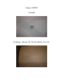
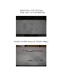
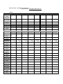
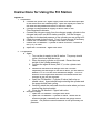
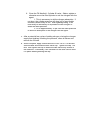
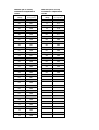
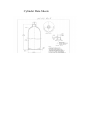
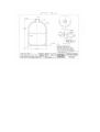
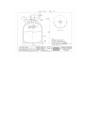
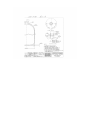
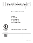
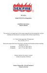
Pre-Engineered
Service Manual
FD and MD Models
Servicing of SEA-FIRE FD and MD Models
When a cylinder arrives for service immediately inspect the box for
damage before signing to except delivery. Document any damage on receiving
documents. We suggest wearing safety glasses and using extreme care when
receiving, unpacking and inspecting a returned cylinder. Cylinders damaged
during shipment may discharge at any time. Carefully open the box and save it
and the packing material then inspect the cylinder for damage.
First inspect the manifold/release bracket area for any damage. Damage
in this area can cause the cylinder to discharge prematurely if bumped. Be sure
the safety pin is in place. If it is not and there is no damage to the release bracket
and it can be inserted without force, insert the safety pin. Do not insert the pin if
the release bracket is damaged and never attempt to force a safety pin in place.
If the release bracket is damaged or the pin cannot be easily inserted, carefully
remove damaged release brackets before further handling of the cylinder.
After the cylinder is deemed safe to handle complete the inspection of the
cylinder. If damaged document the damage. Use pictures to document damage
whenever possible. If the damage is determined to have occurred during
shipment decide if a damage claim on the carrier will be filed. If so hold the box,
packing material and cylinder until the claim is closed. If no claim is to be filed the
packing materials can be discarded and the cylinder can be processed as
required.
Typical damage seen on returned cylinder
Identify the cylinder type/model and determine the correct parts needed for use
in:
Repair of the cylinder
Get the model number off the label, (EX. “FD400M”). If there is no label or the
label is damaged and the model number cannot be read more information will be
needed. Get the agent type from the main label (EX. FM200, HFC227) Weigh
and record the cylinder weight. Look at the writing stamped along the top of the
cylinder (TPED cylinders have markings around the cylinder just above the base)
to identify the cylinder type (EX. TC-3ALM69, DOT39, 3AL1000, 4BW500) and
the cylinder manufacture date (EX. 10 08 = October 2008). An alternate method
of identification is to match up the dimensions of the cylinder to the cylinder data
sheet . DOT39 cylinders cannot be serviced they must be replaced. 3AL1000
and 4BW500 cylinders are certifiable for 12 years.
Owners of cylinders in for service that are over 10 years old should be informed
and given a choice to repair as is, hydrostatic test to extend the service life to 6
more years then repair or to purchase a replacement.
Service Parts for FD and MD Models
Manifold Glue-Up Assembly
Model
Part #
FD 150-1000
131-137
FD 1050-1500
MD 150-1000
131-138
131-156
MD 1050-1500
131-157
Identify model, disassemble cylinder, select part and cut to match length. Install and
torque all models to 120 FT.LBS.
O-Rings
Model
Part#
FD 150-1000
FD 1050-1500
MD 150-1000
MD 1050-1500
121-224 (3), N/A
121-224 (3), 121-221 (1)
121-224 (3), 121-221 (1)
121-224 (3), 121-221 (1)
Use 121-221 under Relief Valve 121-224 in all other manifold ports.
Gauges
Model
FD 150-1000
FD 1050-1500
MD 150-1000
MD 1050-1500
Part#
121-020
121-020
121-020
121-020
PSI
360
360
360
360
NOTE: 3AL-1000 and 4BW500 Cylinders use 360 gauges. Old builds using 4BW360
cylinders cannot be pressurized to 360PSI and require a different 240PSI gauge that must
be special ordered.
Relief Valve
Model
FD 150-1000
FD 1050-1500
MD 150-1000
MD 1050-1500
Part #
N/A
122-130
122-130
122-130
Install and torque all models to 15 FT. LBS.
Tank Valve
Model
FD 150-1000
FD 1050-1500
MD 150-1000
MD 1050-1500
Part#
121-016
121-016
121-016
121-016
Switch
Model
FD 150-1000
FD 1050-1500
MD 150-1000
MD 1050-1500
Part#
124-006
124-007
124-006
124-007
NOTE: Switches can have three different connectors: Standard, Delphi, or Deutsch. You
must match the correct connector.
Release Brackets Standard Pull
Model
FD 10-1000
FD 1050-1500
MD 150-1000
MD 1050-1500
Part #
130-206
130-207
130-206
130-207
Release Brackets Reverse Pull
Model
FD 150-1000
FD 1050-1500
MD 150-1000
MD 1050-1500
Part #
130-208
130-209
130-208
130-209
Loctite All Models
Thread Locker
Loctite 554
Loctite 545
Part#
121-195
121-071
Tie All Models
Corrosion Inhibitor All Models
Agent FM-200 (HFC227) All Models
Part # 121-085
Part # 121-040
Part # 131-100
Tags
For DOT #3AL/1000 & #4BW/500
Tag
Inspection Tag
Safety Tag
Caution Tag
Pressure/Temperature
Part #
123-029
123-025
123-024
123-231
NOTE: For DOT #4BW/360 use pressure/temperature tag #123-230
Tools All Models
Tool
Number Drive Adaptor 7/8” Manifold
Drive Adaptor ¾” Manifold
1/2” Deep socket, 1/2” Drive
Combination Wrench 7/16”
Combination Wrench 9/16”
Torque Wrench 1/2” Drive
Torque Wrench 3/8” Drive
Valve Core removal & Recovery tool
Infrared Thermometer
Part
128-002
128-003
N/A
N/A
N/A
N/A
N/A
N/A
N/A
Manifold Glue-Up Assembly
131-137
131-138
131-156
131-157
Gauge 360PSI
120-020
O-Rings Black 121-224 & White 121-221
Relief Valve 122-130 (Top)
Tank Valve 121-016 (Bottom)
Switch 124-006 (Grey) & 124-007 (Blue)
Release Brackets Standard Pull 130-206 (Left)
130-207 (Right)
Release Brackets Reverse Pull 130-208 (Left)
130-209 (Right)
Sea-Fire Disassembly and Rebuild Procedure
Agent Recovery and Cylinder Disassembly
1. Recover the agent from the cylinder using an approved gas recovery
system.
2. Ensure the cylinder gas is expelled from the system by removing the
Schrader valve cap on the rear of the system, as shown below with a 9/16
wrench, and then depress the core. A refrigerant hose with the
appropriate fitting and 6” of hose works well.
Disassembly
1. Obtain an Assembly Repair Log Sheet. Record the original batch number
stamped on the top of the manifold. Record the RA#, date, initials of the
person performing the repair and the Model number off the label.
2. When gas is completely expelled, remove the Manifold assembly on the
cylinder with the spanner wrench provided (or large pipe wrench with an
extension bar if necessary), by turning it counter-clockwise. A pipe
wrench will most likely gouge the manifold making it un-usable again.
3. Remove any excess material from the inner threads of the cylinder. The
best method is to use either a toothbrush or a soft wire brush followed by
a clean cloth.
Assembly
1. Assemble the parts to be used to make the repair. Record the part number
and PO. Number of each part in each space provided.
2. Using the O-Ring lubricant provided, apply a thin coat to the O-Ring
groove of the cylinder with a clean cloth or tooth brush.
3. Apply Loctite 545 to threads of the cylinder, putting the loctite bottle into
the throat and rotating it. Apply a generous amount, but don’t overdo it.
Ensure that complete coverage – a full ring – is achieved. It is only
necessary to achieve one ring (2 –3 threads, not all threads). Be aware
not to get Loctite on the O-Ring groove.
4. Ensure that the manifold O-ring has some lubrication, if not apply a small
amount around the whole surface.
5. Insert manifold/siphon tube assembly into the cylinder, and tighten with
the manifold socket and torque wrench. Align the socket over the manifold
on the FD and MD 1050 - 1500 and insert a pin through the socket and
into any port in the manifold. On FD150 – 1000 models insert the pin into
the unthreaded unused port. Tighten the manifold to 120 FT- Lbs.
6. Insert a black 121-224 o-ring into the ports to receive the gauge, switch
and Schrader valve. Insert a white 121-221 o-ring into the port to receive
the relief valve if required. Install the pressure gauge, pressure switch,
shrader valve and (relief assembly - FD 1050 and larger models only).
Use loctite 554 for these accessories. Do not allow the Loctite to get on
the pressure gauge lens. It will crack it when it dries.
7. Let the loctite dry for 48 hours. This is a must. Our experience shows
anything less will end up leaking.
Option for Auto/Manual models (Addition of manual trigger
assembly)
1. Insert the lever portion of the trigger through the release bracket.
Locate the bracket on top of the manifold while also aligning the trigger
fingers carefully over the glass bulb. This is a down from the top and
approach from the side maneuver.
2. Use two no. 10-32 screws and 10-32 stainless steel lock washers to
screw down the release assembly. The lever should be somewhat
loose (1/16” or less movement). This is necessary to ensure against
the lever being jammed up or tight.
3. Install the safety pin through the lever and into the hole on the release
assembly.
4. Install a nylon tie around the throat of the cylinder. Rotate/position the
tie so that the pin holder (hole next to the clamp) is aligned for easy pin
storage.
Leak Test and Pressure Switch check for All 3AL-1000 and 4BW500
cylinders.
NOTE: 4BW360 cylinders are pressurized to 240PSI and are not
covered using this process.
1. Fill unit with nitrogen to 360 p.s.i. for leak detection purposes.
2. Leak test unit with a Leak Detector or by using a bucket, tub or tote
filled with water that is large enough to submerse the whole unit.
Submersing the unit and check for any air bubbles that may arise.
Particular attention needs to be made to each threaded mating joint,
the glass bulb and piston area. It is necessary to rotate the cylinder to
focus on each mating joint. Even a minor bubble is an indication of
leakage. This whole process should take 5 minutes per cylinder.
3. Check the pressure switch for proper function under pressure.
Connect the two leads to a voltmeter/continuity checker or other circuit
tester. We have a 12V DC power supply hooked up to a piezo buzzer
all in series – connecting the pressure switch makes the circuit and the
buzzer sounds.
Agent Fill
1. When you are assured that the unit is leak free, release the nitrogen
from the unit, and fill with the appropriate amount of FM-200 and
determine the temperature of the cylinder.
2. Use the chart to determine the proper final pressure based on the
cylinder temperature. Fill unit with nitrogen to that pressure. Fill to
approximately 10 psi over the rated pressure to allow for absorption of
the nitrogen into the agent.
3. Shake or roll the filled cylinder to agitate and mix the nitrogen into the
agent. This is necessary to aid the nitrogen absorption. If not done,
the cylinder pressure will drop (out of serviceable condition) within a
day or two. After agitating/rolling, it will most likely be necessary to repressurize with nitrogen to attain the rated pressure. Repeat until the
pressure is stable. Fill with nitrogen using a reliable/precise regulator
and compare to a calibrated gauge and also the gauge on the cylinder
as the final reference.
4. When complete, apply a small amount of Loctite 554 to the shrader
valve threads and install the shrader valve cap. Tighten the cap.
Repeat the leak test procedure
1. Repeat the underwater portion of the leak test. We have seen shrader
valves leak after being filled where they did not leak initially.
Corrosion Inhibitor
1. Apply a light coat of “wax” (CRC SP-400) to the entire manifold assembly.
This is done by using a 1” paint brush or by setting up a dip tank and
dipping the entire head assembly. The dip tank would need to be at least
6” deep and approximately 10” wide. We use the bottom portion of a 5
gallon pail, cut off. For low volume, the brushing is probably best.
2. Allow the wax to dry for 45 minutes or longer, until it is dry to the touch. A
fan set up to blow across the surface helps shorten the dry time.
Final Documentation
1. When unit is filled and charged and waxed, record the weight. This will be
different for each cylinder depending on weld of the cylinder and the
precision/ repeatability of the filling process. Label the cylinder properly. Send
a copy of the completed Assembly Repair Log Sheet ( FAX or Email) to SEAFIRE Quality Dept.
METALCRAFT / SEAFIRE AUTOMATICS
DESCRIPTION: ASSEMBLY REPAIR LOG
TABLE 1
RECORD OF TRACEABILITY AND INSPECTION
ORIG
BATCH#
BATCH/RA#
NEW ID
Number
DATE
QTY
OPER.
Model
Description
MANIFOLD
Glue-Up Assy
Part #
O-ring
Part #
INSPECT
GAUGE
Part #
SHRADER
Part #
SWITCH
Part #
RELIEF
VALVE
Part #
RELEASE
Part#
TIE
Part #
OPERATOR
DATE
COMP.
LOCTITE
CURE DATE
FILLER
INITIALS
LEAK
TESTER
Final Inspect
STAMP
QTY
ACC.
PO#
BATCH#
PO#
BATCH#
B-
B-
TORQUE
LBS
TORQUE
LBS
PO#
BATCH#
B-
TORQUE
LBS
PO#
BATCH#
B-
TORQUE
LBS
PO#
BATCH#
B-
TORQUE
LBS
PO#
BATCH#
B-
TORQUE
LBS
PO#
BATCH#
B-
TORQUE
LBS
PO#
BATCH#
B-
TORQUE
LBS
Instructions for Using the Fill Station
Agent Fill
1. Preparation
a. Connect the yellow 3/8” agent supply hose from the tank liquid port
to the inlet side of the Haskell pump. Open the liquid port valve on
the tank and any additional valves in the hose setup.
b. Connect a compressed air supply to the air inlet on the
Filter/Regulator/Lubricator.
c. Connect the nitrogen supply from the nitrogen supply cylinder to the
nitrogen inlet valve on the fill station manifold. Set the nitrogen
regulator to the desired pressure of the cylinder you are going to fill.
d. Check the scale for being level. Turn it on and ensure its accuracy.
e. Ensure the Fill Manifold – Nitrogen inlet valve is closed.
f. Ensure the Fill Manifold - Cylinder fill valve is closed. Connect a
red (1/4”) fill hose.
g. Open the Fill manifold – Agent inlet valve.
2. Fill Operation
a. Agent
i. Turn on the air supply to the fill station. The pump should
cycle a few times and then stop.
ii. Place the empty cylinder on the scale. Record the tare
weight of the cylinder assembly.
iii. Connect the agent fill hose (Red ¼”) to the cylinder tank
valve.
iv. Determine the desired fill weight from the Fill chart.
Depending on the length of the red fill hose, you will have to
deduct 0.15 to 0.25 lbs from the desired weight. This is to
account for the agent that remains in the hose before the
nitrogen is put into the cylinder.
v. Open the Fill Manifold - Cylinder fill valve (ball valve or
needle valve). Agent should begin entering the cylinder and
the pump should start cycling.
vi. Carefully watch the scale and close the valve when you have
reached the desired weight.
vii. Close the Fill Manifold – Agent Inlet valve
b. Nitrogen Charge
i. Open the Fill manifold - nitrogen inlet valve.
ii. Open the Fill Manifold - Cylinder fill valve. Watch the fill
manifold gauge (Calibrated) as well as the gauge on the
cylinder. The pressure should stabilize on the previously set
pressure.
iii. Close the Fill Manifold - Cylinder fill valve. Shake, agitate or
otherwise move the filled cylinder to mix the nitrogen with the
agent.
1. This is necessary to aid the nitrogen absorption. If
not done, the cylinder pressure will drop (out of serviceable
condition) within a day or two. After agitating/rolling, it will
most likely be necessary to re-pressurize with nitrogen to
attain the rated pressure.
2. Fill to approximately 10 psi over the rated pressure
to allow for absorption of the nitrogen into the agent.
c. After a potential few cycles of adding nitrogen, closing the nitrogen
supply and shaking/ checking the pressure, close all valves and
remove the fill hose.
d. When complete, apply a small amount of Loc-Tite 277 to the tank
valve threads and install the tank valve cap. Tighten the cap. DO
NOT over tighten the cap to where the tank valve body moves in
the manifold. If necessary, use a wrench on the tank valve to hold
it in place when tightening the cap.
Recycling/ Recovering Agent
1. Disconnect the yellow 3/8” Feed hose from the inlet side of the pressure
gauge assembly.
2. Connect the free end of the hose to the tank where you want the recovered
agent to go. This could be the vapor side of the main source tank you are using
to fill out of, or another suitably rated pressure tank.
Note: when you recover FM-200 from a filled extinguisher, you will also get
nitrogen. This nitrogen will eventually need to be bled off or otherwise removed.
That is why we recommend a separate holding tank to recover the FM-200 into.
After the nitrogen is removed, you can then fill out of this tank.
Another point is, if your main source tank is full, or near full, you will not be able
to pump any recovered FM-200/ nitrogen into it. The same applies to your
holding tank, if it’s full; you need to pump out of it before recovering any more.
3. Ensure that the liquid/ supply valve is closed on the main supply tank.
Note: You do not need to remove the 3/8” hose that is connected from the tank to
the pump as long as the valve is closed.
4. Remove the ¼” fill hose from the gauge assembly completely, or use another
of the same style hose.
5. Remove the cap off the shrader valve on the ball valve, on the inlet side of the
pump.
6. Connect one end of the ¼” hose to this shrader valve, the other end to the
bottle that needs to be emptied.
Bottle Preparation – cylinder to be emptied
7. Remove the cap off the shrader valve.
Option: Turn the shrader core ¼ to ½ turn counter clockwise. This will
help the agent flow out of the bottle faster. Do not remove it too far or
the agent will expel from the valve.
8. Lay the bottle horizontal.
9. Connect the ¼” hose from the pump to the cylinder (repeat of step 6)
10. Turn on the compressed air supply to the pump and drain until the gauge
reads no pressure and the cylinder feels empty.
Note: Rock the cylinder slowly until it feels like no liquid remains. The bottle
should be empty.
FILL CHART - FD & MD Manual and Automatics - FM 200
MODEL
FD/MD
AGENT
WEIGHT
(LBS.)
CHARGE
PRESSURE
(P.S.I.G.)@
70F
AGENT
WEIGHT
(KGS.)
CHARGE
PRESSURE
(BAR) @
21C
150
6.50
360
2.95
24.8
175
7.58
360
3.44
24.8
200
8.66
360
3.94
24.8
225
9.74
360
4.43
24.8
250
10.83
360
4.92
24.8
275
11.91
360
5.41
24.8
300
12.99
360
5.90
24.8
325
14.07
360
6.40
24.8
350
15.16
360
6.89
24.8
375
16.24
360
7.38
24.8
400
17.32
360
7.87
24.8
425
18.40
360
8.36
24.8
450
19.49
360
8.86
24.8
475
20.57
360
9.35
24.8
500
21.65
360
9.84
24.8
525
22.73
360
10.33
24.8
550
23.82
360
10.83
24.8
575
24.90
360
11.32
24.8
600
25.98
360
11.81
24.8
625
27.06
360
12.30
24.8
650
28.15
360
12.79
24.8
675
29.23
360
13.29
24.8
700
30.31
360
13.78
24.8
725
31.39
360
14.27
24.8
FILL CHART - FD & MD Manual and Automatics - FM 200
MODEL
FD/MD
AGENT
WEIGHT
(LBS.)
CHARGE
PRESSURE
(P.S.I.G.)@
70F
AGENT
WEIGHT
(KGS.)
CHARGE
PRESSURE
(BAR) @
21C
750
32.48
360
14.76
24.8
775
33.56
360
15.25
24.8
800
34.64
360
15.75
24.8
825
35.72
360
16.24
24.8
850
36.81
360
16.73
24.8
875
37.89
360
17.22
24.8
900
38.97
360
17.71
24.8
925
40.05
360
18.21
24.8
950
41.14
360
18.70
24.8
975
42.22
360
19.19
24.8
1000
43.30
360
19.68
24.8
1025
44.38
360
20.17
24.8
1050
45.47
360
20.67
24.8
1075
46.55
360
21.16
24.8
1100
47.63
360
21.65
24.8
1125
48.71
360
22.14
24.8
1150
49.80
360
22.63
24.8
1175
50.88
360
23.13
24.8
1200
51.96
360
23.62
24.8
1225
53.04
360
24.11
24.8
1250
54.13
360
24.60
24.8
1275
55.21
360
25.09
24.8
1300
56.29
360
25.59
24.8
1325
57.37
360
26.08
24.8
FILL CHART - FD & MD Manual and Automatics - FM 200
MODEL
FD/MD
AGENT
WEIGHT
(LBS.)
CHARGE
PRESSURE
(P.S.I.G.)@
70F
AGENT
WEIGHT
(KGS.)
CHARGE
PRESSURE
(BAR) @
21C
1350
58.46
360
26.57
24.8
1375
59.54
360
27.06
24.8
1400
60.62
360
27.55
24.8
1425
61.70
360
28.05
24.8
1450
62.79
360
28.54
24.8
1475
63.87
360
29.03
24.8
1500
64.95
360
29.52
24.8
FM-200 (HFC 227ea)
Pressure/Temperature
Chart
360 Psi @
Temp
70 F(21C)
40
320
41
321
42
322
43
324
44
325
FM-200 (HFC 227ea)
Pressure/Temperature
Chart
360 Psi @
Temp
70 F(21C)
76
369
77
371
78
372
79
374
80
375
45
326
81
377
46
47
48
49
50
327
329
330
331
333
82
83
84
85
86
378
380
381
383
385
51
334
87
386
52
53
54
55
56
335
337
338
339
340
88
89
90
91
92
388
389
391
393
394
57
342
93
396
58
59
60
61
62
343
345
346
347
349
94
95
397
399
63
350
64
65
66
67
68
352
353
354
356
357
69
359
70
71
72
73
74
360
362
363
365
366
75
368
Cylinder Data Sheets
125-037