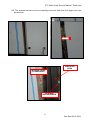
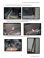
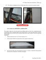
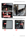
1
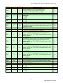
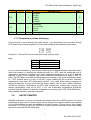
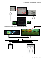
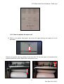
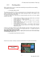
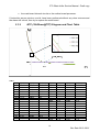
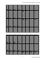
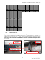
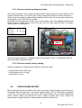
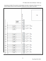
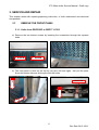
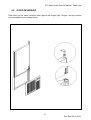
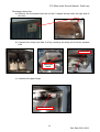
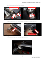
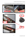
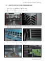
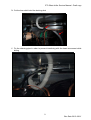
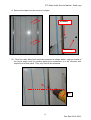
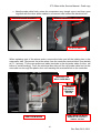
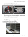
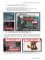
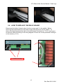
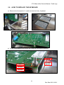
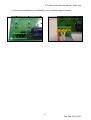
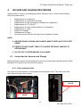
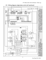
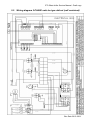
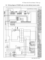
ETL BLAST CHILLER SERIES
SERVICE MANUAL
1.
BASIC SERVICE INSTRUCTION ................................................................................ 1
1.1. ALARM/FAILURE LIST .......................................................................................... 1
1.2. ALARM LIST CHECK ............................................................................................ 2
1.3. SERVICE MENU (PARAMETER SETTING) .......................................................... 2
1.3.1. Enter the parameter list ...................................................................................... 2
1.3.2. Parameter list (factory setting) ........................................................................... 2
1.3.3. Temperature probes displaying.......................................................................... 7
1.4. HACCP PRINTER ................................................................................................. 7
1.4.1. Printing alarm list ............................................................................................... 9
1.4.2. Printing cycle data............................................................................................ 10
1.4.3. How to replace the paper roll ........................................................................... 11
2.
TROUBLESHOOTING ............................................................................................... 12
2.1. PROBES ............................................................................................................. 12
2.1.1. CHECKING PROBES ................................................................................................ 13
2.1.2. NTC (10KOHMS@77°F) DIAGRAM AND CHART TABLE ............................................. 14
2.2. DOOR SWITCH ................................................................................................... 16
2.2.1. Checking the door switch ................................................................................. 17
2.3. PRESSURE SWITCH .......................................................................................... 17
2.3.1. Pressure switch working principles .................................................................. 18
2.3.2. Pressure switch factory setting ........................................................................ 18
2.4. DOOR FRAME HEATER ..................................................................................... 18
2.4.1. Heater cable features ....................................................................................... 19
2.5. MAIN BOARD ...................................................................................................... 19
2.5.1. Checking relay outputs .................................................................................... 19
2.6. KEYBOARD......................................................................................................... 21
2.6.1. Keyboard Troubleshooting ............................................................................... 21
2.7. REFRIGERANT PRESSURES CHECK ............................................................... 21
3.
SERVICE AND REPAIR............................................................................................. 23
3.1. REMOVE THE FRONT PANEL ........................................................................... 23
3.1.1. UNITS FROM GBC30SG TO GBF171-132S ............................................................ 23
3.1.2. GBF15-11S (smallest self-contained unit) ....................................................... 24
3.2. DOOR REVERSING ............................................................................................ 25
3.3. HOW TO ACCESS TO THE CONDENSING UNIT ............................................... 30
3.3.1. Units from GBC39S to GBF171-132S .............................................................. 30
3.3.2. Units from GBC30SG to GBF44-26SP ............................................................ 35
3.3.3. GBF15-11S (smallest self-contained unit) ....................................................... 37
3.3.4. Remote units, units GBF440-385R and GBF837-727R ................................... 38
3.4. HOW TO ACCESS EVAPORATOR ASSY........................................................... 38
3.4.1. Evaporator assy description ............................................................................. 38
3.4.2. How to access to the evaporator...................................................................... 39
3.4.3. How to replace cabinet, evaporator or needle probe ....................................... 40
3.4.4. How to replace evaporator motor fans ............................................................. 42
3.5. HOW TO REPLACE THE DOOR SWITCH .......................................................... 42
3.5.1. GBF15-11S (smallest self-contained unit) ....................................................... 42
3.5.2. Units from GBC30SG to GBF171-132S ........................................................... 43
3.6. HOW TO REPLACE THE PRESSURE SWITCH ................................................. 43
3.7. HOW TO REPLACE THE DOOR FRAME HEATER ............................................ 44
3.8. HOW TO REPLACE THE RELAY BOARD........................................................... 45
3.9. HOW TO REPLACE THE KEYBOARD ................................................................ 46
4.
VACUUM AND CHARGE PROCEDURE ................................................................... 48
4.1 INSTRUCTION FOR VACUUM AND CHARGE .................................................................... 48
4.1.1. Self contained units.......................................................................................... 48
4.1.2. Remote units .................................................................................................... 49
4.1.3. Vacuum and charge recommendations ........................................................... 49
5.
SCHEMES AND WIRING DIAGRAMS ...................................................................... 50
5.1.
5.2.
5.3.
5.4.
SCHEME OF COMPONENTS ...................................................................................... 50
WIRING DIAGRAM SINGLE PHASE UNITS (SELF CONTAINED) ......................................... 51
WIRING DIAGRAM 3-PHASE UNITS HOT GAS DEFROST (SELF CONTAINED) .................. 52
WIRING DIAGRAM 3-PHASE UNITS NO ACTIVE DEFROST (REMOTE UNITS) ................... 53
I.
HOW TO READ THE MODEL NUMBER ................................................................... 54
II.
DATA CHART TABLE ............................................................................................... 55
ETL Blast chiller Service Manual - Draft copy
1. BASIC SERVICE INSTRUCTION
The controller provides alarm and failure codes to shortly identify roots of problems and go
investigating directly the concerned parts. Furthermore a service submenu allows
technicians to check rapidly all the sensors, scrolling room/needle/evaporator
temperatures.
1.1.
ALARM/FAILURE LIST
Tab 1
CODE
Er0
Er1
Er3
HP
d-r
AH
AL
Err
Res
CAUSE
ROOM PROBE FAILURE
CONSEQUENCE
Doesn’t allow to run any cycle. If a
cycle is running, it is forced to stop.
EVAPORATOR PROBE FAILURE
During storage, evaporator fans are
cut out.
NEEDLE PROBE FAILURE
Doesn’t allow to run a needle probe
set temperature cycle. If a needle
probe cycle is running, it is forced to
stop.
HIGH DISCHARGE PRESSURE (OR Doesn’t allow to run any cycle. If a
LOW SUCTION PRESSURE)*
cycle
is
running,
compressor,
evaporator and condenser fans are
cut out.
DOOR IS OPEN FOR MORE THAN Compressor and condenser fan are
P39
cut out. Evaporator fan are cut in/out
according to parameter P37
HIGHT ROOM TEMPERATURE
Nothing happens
LOW ROOM TEMPERATURE
Nothing happens
MOTHER BOARD-KEYBOARD
Nothing happens
CONNECTION FAILURE **
POWER FAILURE DURING
The cycle starts again as soon as
RUNNING OF CYCLE
power is restored. The message Res
blinks to indicate the cycle has been
resumed.
*Although the controller board is equipped with one additional dedicated input for low
pressure switch, pressure switch device installed in this series can only provide a single
output (closed or opened). The high/low pressure switch is connected among terminals
#48-49. The circuit is normally opened, it closes both when high/low pressure limits are
exceeded. So the code failure “HP” could mean actually a high discharge pressure as well
as a low suction pressure.
**Deep troubleshooting on connection failure between keyboard and interface board (look
at RS 485 (1):
1. GND wire connection missing: The display digits blink and grow dim
2. - wire connection missing: display might work, without giving any specific alarm
3. + wire connection missing: Err is displayed
4. 12V wire missing: no light at all on the display
1
Rev Date 2012-06-21
ETL Blast chiller Service Manual - Draft copy
1.2.
ALARM LIST CHECK
Thanks to the HACCP features, the controller allows to check the occurred alarm. It
provides alarm codes, date of alarm, maximum/minimum occurred temperature (if dealing
with a high/low temperature alarm), alarm duration. To access the alarm log list (only
possible during OFF mode) keep pressed the program key for 5 seconds
All the information concerning the alarm will be displayed. To scroll through the alarms use
the up/down keys. To exit press the program key.
1.3.
SERVICE MENU (PARAMETER SETTING)
1.3.1. Enter the parameter list
The service menu can be accessed only during OFF mode.
Press the up/down keys
together for 5 seconds to enter the menu. Label PA (password) will be shown as first. The
controller doesn’t need actually any password to configure the parameters. By pressing
the up arrow key the parameter list can be accessed directly (first parameter is P0). Scroll
the parameter by pressing Up/down keys. Select a parameter by pressing the time key
Change the value by up/down keys. Press again time key to save and go back to the list.
1.3.2. Parameter list (factory setting)
The following table shows parameter factory settings for both Blast chiler units (GBC) and
shock freezer (GBF).
Note: Selecting a freezing cycle on a GBC unit will anyway run a normal chilling
cycle (cabinet at 4°F, needle probe end cycle tempe rature at 37°F)
CODE
P0
U.O.M.
GBC
-
0
DESCRIPTION
unit of temperature measurement
0 = °F
GBF
0
2
Rev Date 2012-06-21
ETL Blast chiller Service Manual - Draft copy
CODE
U.O.M.
GBC
P1
P2
P3
GROUP
°F
°F
°F
-
4
0
0
-
P4
°F
20
P5
°F
-4
P6
°F
-4
P7
°F
37
P8
°F
-4
P9
°F
2
P10
°F
37
P11
°F
37
P12
°F
46
P13
°F
99
P14
°F
9
P15
s
60
P16
min
90
P17
min
90
P18
GROUP
min
-
45
-
P19
min
0
P20
min
0
P21
GROUP
min
-
0
-
DESCRIPTION
GBF
1 = °C
4
cabinet probe offset
0
evaporator probe offset
0
needle probe offset
MAIN CONTROLLER
operational setpoint during the second hard chill
20
step; also, operational setpoint during normal chilling
(with reference to the cabinet probe)
operational setpoint during freezing (with reference to -40
the cabinet probe)
operational setpoint during the first hard chill step
-4
(with reference to the cabinet probe)
operational setpoint during post-chill storage (with
37
reference to the cabinet probe)
operational setpoint during post-freeze storage (with
-4
reference to the cabinet probe)
2
P4, P5, P6, P7 and P8 differential
set temperature chill end temperature (with reference
37
to the needle probe)
set temperature freeze end temperature (with
0
reference to the needle probe)
temperature at which the hard chill switches from the
first step to the second (with reference to the needle
46
probe)
temperature above which it is not possible to start a
set-temperature operational cycle (with reference to
99
the needle probe)
needle probe and cabinet temperature gap for
9
verification of correct needle probe insertion
0 = the test will not be performed
duration of the second test to check correct needle
60
probe insertion; see also P14
maximum set temperature chill duration; also timed
90
chill duration
maximum set temperature freeze duration; also
270
timed freeze duration
45
first hard timed chill step duration
COMPRESSOR PROTECTIONS
compressor delay from device power on (from
0
restoration of power)
minimum elapsed time period between two
0
consecutive compressor start-up operations
0
minimum compressor shut-down time
DEFROSTING
3
Rev Date 2012-06-21
ETL Blast chiller Service Manual - Draft copy
CODE
U.O.M.
GBC
P22
-
1
P23
°F
46
P24
min
10
P25
h
6
P26
min
1
P27
-
1
P28
min
2
P29
-
0
P30
s
30
P31
s
0
GROUP
-
-
P32
°F
37
P33
°F
2
P34
-
0
P35
min
3
P36
°F
99
P37
-
1
GROUP
-
-
P38
-
1
P39
min
0
DESCRIPTION
GBF
defrost type
0 = electric (defrost on relay)
1 = hot gas (defrost compressor and relay on)
2 = air (evaporator fan on)
defrost end temperature (with reference to the
evaporator probe)
maximum defrost duration
defrost interval during storage; see also P26
0 = intermittent defrosting will never be activated
(only the first will be activated)
first defrost delay from start of storage; see also P25
defrosting at start of chilling and freezing
1 = YES
drip-drain duration
resetting of compressor protections at start of
defrosting (only if P22 = 1)
1 = YES
elapsed time between the defrost request and
switching on the compressor (only if P22 = 1 and
providing that the compressor is off when the defrost
is requested); see P31 (7) (8)also
elapsed time between the defrost request and
activation of the solenoid valve (only if P22 = 1 and
on condition that the compressor is off when
defrosting is requested); see also P30
EVAPORATOR FAN
temperature above which the evaporator fan is
switched off during storage (with reference to the
evaporator probe)
P32 differential
evaporator fan activity during defrosting (only if P22 =
0 or 1)
0 = on
1 = off
evaporator stop time after dripping
temperature above which the evaporator fan is
switched off (with reference to the cabinet probe)
effect caused by activation of microport input on
evaporator fan
0 = no effect
1 = the evaporator fan will be switched off
DIGITAL INPUTS
microport input contact type
0 = NA (input active with contact closed)
1 = NC (input active with contact open)
micro port input alarm delay
1
46
10
6
1
1
2
0
30
0
37
2
0
3
99
1
1
0
4
Rev Date 2012-06-21
ETL Blast chiller Service Manual - Draft copy
CODE
U.O.M.
GBC
P40
-
1
P41
min
120
P42
-
0
P43
min
0
P44
-
0
min
min
-
0
5
-
P47
°F
99
P48
GROUP
s
-
15
-
P49
°F
41
P50
GROUP
°F
-
4
-
P45
GROUP
P46
GROUP
P51
-
1
P52
°F
68
P53
°F
9
P54
s
30
GROUP
P55
P56
s
s
3
15
P57
s
10
DESCRIPTION
GBF
high pressure input contact type
1
0 = NA (input active with contact closed)
1 = NC (input active with contact open)
120
high pressure input alarm delay
low pressure input contact type
0
0 = NA (input active with contact closed)
1 = NC (input active with contact open)
0
low pressure input alarm delay
compressor thermal protection input contact type
0
0 = NA (input active with contact closed)
1 = NC (input active with contact open)
0
compressor thermal protection input alarm delay
CABINET STERILISATION
5
UV light on duration (duration of cabinet sterilisation)
NEEDLE PROBE HEATING
needle probe heating end temperature (with
99
reference to the needle probe)
15
maximum duration of needle probe heating
DOOR ELEMENTS
the temperature, below which the door elements are
41
switched on (with reference to the cabinet probe)
4
P49 differential
CONDENSER FAN
condenser fan activity in the absence of the
condenser probe (P61 = 0)
0 = in parallel with compressor
1 = on
the temperature below which the condenser fan is
switched off in the presence of the condenser probe
(P61 = 1) and on condition that the compressor is on
(with reference to the condenser probe); see also
P54
P52 differential
condenser fan switch off delay on switching off the
compressor in the presence of the condenser probe
(P61 = 1); see also P52
MISCELLANEOUS
chill and freeze cycle completion buzzer duration
maximum buzzer duration during an alarm state
elapsed time between switching on the compressor
and pump down valve activation (pump down in
power up); also elapsed time between deactivation of
the pump down valve and switching off the
compressor (pump down in power down)
1
68
9
30
3
15
10
5
Rev Date 2012-06-21
ETL Blast chiller Service Manual - Draft copy
CODE
U.O.M.
GBC
P58
-
0
P59
-
0
P60
-
0
P61
-
0
GROUP
-
-
P62
°F
99
P63
GROUP
°F
-
18
-
P64
°F
0
P65
°F
0
P66
°F
0
P67
°F
0
°F
min
min
-
4
0
0
-
P71
-
0
P72
min
5
P73
-
0
P68
P69
P70
GROUP
DESCRIPTION
defrost parameter units of measurement
0 = P25 h, P24, P26, P28 and P35 min
1 = P25 min, P24, P26, P28 and P35 s
reserved
probe type
0 = NTC
1 = PTC
condenser probe enabling
1 = YES
CONDENSER TEMPERATURE ALARMS
the temperature above which the condenser
temperature alarm is activated (with reference to the
condenser probe)
P62 differential
CABINET TEMPERATURE ALARMS
temperature below which the minimum temperature
alarm is activated during post-chill storage, with
relation to P7, i.e. "P7 + P64" (with reference to the
cabinet probe)
0 = no alarm
temperature above which the maximum temperature
alarm is activated during post-chill storage, with
relation to P7, i.e. "P7 + P65" (with reference to the
cabinet probe)
0 = no alarm
temperature below which the minimum temperature
alarm is activated during post-freezing storage, with
relation to P8, i.e. "P8 + P66" (with reference to the
cabinet probe)
0 = no alarm
temperature above which the maximum temperature
alarm is activated during post-freezing storage, with
relation to P8, i.e. "P8 + P67" (with reference to the
cabinet probe)
0 = no alarm
P64, P65, P66 and P67 differential
storage operation start-up temperature alarm delay
temperature alarm delay
DATA PRINTING
enable printing
1 = YES
print interval
HACCP alarm list deletion
1 = YES
GBF
0
0
0
0
99
18
-
0
0
0
0
4
0
0
0
5
0
6
Rev Date 2012-06-21
ETL Blast chiller Service Manual - Draft copy
CODE
P74
U.O.M.
-
GBC
2
P75
-
2
P76
-
1
DESCRIPTION
Baudrate
0=2400
1=4800
2=9600
3=19200
GBF
2
Bit polarity
0=no polarity
1=even
2=odd
Board address
2
1
1.3.3. Temperature probes displaying
A quick mode to check directly the probe values, is by provided by the controller. During
OFF mode keep pressed together for 5 seconds needle probe and down arrow keys
Labels Pr1, Pr2 and Pr3 can be scrolled through up/down keys
Tab 2
LABEL
Pr1
Pr2
Pr3
RELATED PROBE
cabinet probe
needle probe
evaporator probe
A very useful information is provided by checking the evaporator probe, especially when
there are troubles in reaching the cabinet set point (i.e. -40°F) and the evaporator coil is
supposed to be starved or short of gas. When cabinet temperature is set to -40 °F and the
setpoint is going to be reached, the actual evaporator temperature is approx -49°F (0
psig). The Pr3 label, seen after shutting down the controller, may show temperature down
to – 42°F (indeed there is a limit in the NTC signa l reading by the controller, therefore
temperature lower than -42°F will be never shown). I any case, when there is a suspect of
starved evaporator, a quick proof with the empty cabinet can be done. Within maximum
40-50mins (ambient temperature at 90°F) with compre ssor continuously running, the
cabinet temperature must be at -40°F. If not, the e vaporator temperature should be
checked from the display. Evaporator temperature not going under -22°F within 40/50mins,
may probably indicate a starved evaporator.
1.4.
HACCP PRINTER
Detailed instruction on how to use/install and trouble shoot the HACCP printer, are worth
mentioning in this manual. Printer option can be ordered as a special option upon request
for the blast chillers, as well as installed as a retrofit device. Printer has its own supply
connector (110 VAC to 240 VAC 50/60 Hz). Printer must be connected to the main board
through the second RS 485 serial port.
7
Rev Date 2012-06-21
ETL Blast chiller Service Manual - Draft copy
A belden shied cable (3 wires) must be preferably used.
45
PRINTER TERMINAL BLOCK
RS485 (2)
46
47
MAIN BOARD TERMINAL BLOCK
8
Rev Date 2012-06-21
ETL Blast chiller Service Manual - Draft copy
The main controller must be set to enable printer/main board communication. The
parameter that needs to be configured is P71 (set it at 1 to enable RS485 (2) printer port).
Furthermore ensure that P76=1, P75=2 and P74=2. An On/Off LED shows the printer
device status (red is On).
By pressing the Feed key is possible to output blank paper (both during On or Off status).
1.4.1. Printing alarm list
To print the alarm list the controller must be in Off mode. The beginning procedure is the
same than checking the alarm list: press the program key for 5 seconds
If the printer communication has been enabled, the first label shown is “Prt”. To print the
alarm list press again the program key
To exit from the printing label press up/down keys:
the alarm list will be only shown on the displayed.
Maximum number of alarm filed is 10. Printed codes are as shown in the Tab 1. Alarm
duration , maximum/minimum temperature, date&hour, alarm number and alarm code are
shown.
9
Rev Date 2012-06-21
ETL Blast chiller Service Manual - Draft copy
1.4.2. Printing cycle data
Thanks to the HACCP printer of course is also possible to print the data history related to
performed freezing/chilling cycle. If the printer is kept On and if a cycle is started, printing
of data starts automatically with the cycle. The data capture frequency is specified by the
parameter P72 (print interval, min). e.g. if P72 is set to 1, the device will print each minute,
providing
•
•
•
Type of cycle (first line above date)
Start date&hour
Time, cabinet and needle probe temperatures (each capture line)
Type of cycle legend:
Tab 3
Cycle code
T*
T***
T>>>*
t*
t***
t>>>*
P1……..99
Description
Needle probe soft chilling
Needle probe freezing
Needle probe hard chilling
Time soft chilling
Time freezing
Time hard chilling
Programmed cycle
10
Rev Date 2012-06-21
ETL Blast chiller Service Manual - Draft copy
1.4.3. How to replace the paper roll
a) Push on the printer front panel, the cover will open allowing the paper roll to be
accessed
Remove the printer roller by pulling it from one side. Fit the new paper roll and place the
paper between the rollers. Reset roller and printer cover.
11
Rev Date 2012-06-21
ETL Blast chiller Service Manual - Draft copy
2. TROUBLESHOOTING
If from a first inspection there isn’t any chance to fix the problem, a deeper troubleshooting
may be necessary. The unit may need to be dismounted and some electrical/mechanical
parts to be checked.
2.1.
PROBES
The blast chiller units are equipped with Negative Temperature Coefficient thermistor
sensors (briefly NTC). Room and evaporator probes have the same exterior structure,
needle probe has a different sensor element. Both probes are anyway NTC type and have
the same resistance Vs Temperature chart.
ROOM/EVAPORATOR PROBE TYPE
NTC PROBE
BULB
PROBE MEASURING
NTC NEEDLE PROBE TYPES
12
Rev Date 2012-06-21
ETL Blast chiller Service Manual - Draft copy
2.1.1.
Checking probes
When a probe alarm occurs, it means that something is wrong with the sensor reading.
The problem may concern:
a. the probe cables or bulb
The probe alarms (Er0, Er1, Er3) are commonly due to an interruption (open circuit) in the
cables. Occasionally it may happen that a probe cable goes short to the chassis, or the
two probe wires go short each other.
To detect the alarm root, disconnect the concerned probe and ohm out the two cables
between each other.
•
•
•
•
If the reading is 0 Ohms it means the probe wires are shorted
between each-other. Replace the probe.
If the reading is ∞, that means the probe circuit is opened.
Replace the probe
If the reading matches with the chart table 3, then the probe
works good, jump to b. or c.
If the reading it’s not 0, neither ∞ and doesn’t match with the
chart table, then the probe may be out of range (very unusual).
Replace the probe.
If none out of 4 above options can be easily detected, then Ohm out the probe wires one
by one against chassis. If the reading is 0 (or anyway less than ∞), it means the probe is
short to the chassis. Replace the probe.
Alternatively and much more rapidly, a spare probe can be used. If the alarm keeps
on buzzing, go to pint b. or c.
b. the probe to board terminal connection
Check for rust, water, humidity, loosen/lost connections on the probe terminal block.
PROBES TERMINAL
BLOCK
13
Rev Date 2012-06-21
ETL Blast chiller Service Manual - Draft copy
c. the main board internal circuits or the mother board processor
If instruction as per points a. and b. have been performed without any clear outcome and
the alarm still occurs, then try to replace the main board.
2.1.2.
NTC (10kOhms@77°F) Diagram and Chart Table
2.1.3 NTC (10kOhms@77°F) Chart Table
Tab 4
T[°F] R[k Ω] low
-40
197,1
-38,2 186,3
-36,4 176,1
-34,6 166,5
-32,8 157,5
-31
149,1
-29,2 141,2
-27,4 133,7
-25,6 126,7
-23,8 120,1
-22
113,9
-20,2 108
-18,4 102,5
-16,6 97,34
-14,8 92,45
-13
87,83
-11,2 83,47
R[kΩ] mid
205,2
193,8
183,1
173,1
163,6
154,8
146,5
138,7
131,3
124,4
117,9
111,8
106
100,6
95,51
90,69
86,15
R[kΩ] high
213,6
201,6
190,4
179,8
170
160,7
152
143,8
136,1
128,9
122,1
115,7
109,7
104
98,67
93,64
88,91
T[°F]
R[k Ω] low
R[kΩ] mid
R[kΩ] high
42,8
44,6
46,4
48,2
50
51,8
53,6
55,4
57,2
59
60,8
62,6
64,4
66,2
68
69,8
71,6
20,98
20,12
19,3
18,52
17,78
17,07
16,39
15,75
15,13
14,54
13,98
13,44
12,92
12,43
11,96
11,51
11,08
21,35
20,47
19,63
18,83
18,06
17,34
16,64
15,98
15,35
14,74
14,17
13,62
13,09
12,59
12,11
11,65
11,21
21,73
20,82
19,96
19,14
18,35
17,61
16,89
16,22
15,57
14,95
14,36
13,79
13,26
12,74
12,25
11,78
11,33
14
Rev Date 2012-06-21
ETL Blast chiller Service Manual - Draft copy
-9,4
-7,6
-5,8
-4
-2,2
-0,4
1,4
3,2
5
6,8
8,6
10,4
12,2
14
15,8
17,6
19,4
21,2
23
24,8
26,6
28,4
30,2
32
33,8
35,6
37,4
39,2
41
79,35
75,47
71,79
68,32
65,04
61,94
59,01
56,23
53,6
51,11
48,75
46,51
44,39
42,38
40,47
38,66
36,94
35,31
33,76
32,29
30,89
29,56
28,29
27,09
25,94
24,85
23,81
22,82
21,88
T[°F] R[k Ω] low
127,4 3,704
129,2 3,585
131
3,471
132,8 3,362
134,6 3,256
136,4 3,154
138,2 3,056
140
2,961
141,8 2,869
143,6 2,781
145,4 2,696
147,2 2,614
149
2,535
150,8 2,459
152,6 2,385
154,4 2,313
156,2 2,245
158
2,178
159,8 2,114
161,6 2,052
81,86
77,81
73,99
70,37
66,96
63,74
60,69
57,8
55,07
52,49
50,04
47,72
45,52
43,44
41,46
39,59
37,81
36,13
34,53
33
31,56
30,19
28,88
27,64
26,46
25,33
24,26
23,24
22,27
84,43
80,22
76,24
72,48
68,93
65,58
62,41
59,41
56,58
53,9
51,36
48,96
46,68
44,52
42,48
40,54
38,7
36,96
35,31
33,73
32,24
30,83
29,48
28,2
26,98
25,83
24,72
23,68
22,68
73,4
75,2
77
78,8
80,6
82,4
84,2
86
87,8
89,6
91,4
93,2
95
96,8
98,6
100,4
102,2
104
105,8
107,6
109,4
111,2
113
114,8
116,6
118,4
120,2
122
123,8
10,67
10,28
9,9
9,532
9,18
8,843
8,52
8,21
7,914
7,63
7,358
7,097
6,847
6,606
6,376
6,155
5,942
5,738
5,542
5,354
5,173
4,999
4,832
4,671
4,517
4,368
4,225
4,087
3,954
10,79
10,38
10
9,632
9,279
8,942
8,619
8,309
8,012
7,727
7,454
7,192
6,941
6,7
6,468
6,246
6,033
5,828
5,631
5,441
5,259
5,084
4,916
4,754
4,598
4,448
4,304
4,165
4,031
10,9
10,49
10,1
9,732
9,379
9,041
8,718
8,407
8,11
7,825
7,551
7,288
7,036
6,794
6,562
6,338
6,124
5,918
5,72
5,529
5,346
5,17
5
4,837
4,68
4,529
4,383
4,243
4,108
R[kΩ] mid
3,778
3,658
3,543
3,432
3,325
3,222
3,123
3,027
2,934
2,845
2,759
2,676
2,595
2,518
2,443
2,371
2,301
2,233
2,168
2,105
R[kΩ] high
3,853
3,732
3,616
3,504
3,396
3,291
3,191
3,094
3
2,91
2,823
2,738
2,657
2,578
2,503
2,429
2,358
2,29
2,224
2,16
T[°F]
210,2
212
213,8
215,6
217,4
219,2
221
222,8
224,6
226,4
228,2
230
231,8
233,6
235,4
237,2
239
240,8
242,6
244,4
R[k Ω] low
0,9505
0,9247
0,8998
0,8756
0,852
0,8292
0,8071
0,7856
0,7647
0,7444
0,7248
0,7057
0,6872
0,6692
0,6518
0,6349
0,6185
0,6026
0,5871
0,5721
R[kΩ] mid
0,9826
0,9563
0,9307
0,9059
0,8818
0,8584
0,8357
0,8136
0,7922
0,7715
0,7513
0,7317
0,7127
0,6943
0,6764
0,659
0,6421
0,6258
0,6099
0,5945
R[kΩ] high
1,016
0,9888
0,9626
0,9372
0,9125
0,8885
0,8653
0,8427
0,8207
0,7994
0,7787
0,7586
0,7391
0,7202
0,7018
0,6839
0,6666
0,6498
0,6334
0,6176
15
Rev Date 2012-06-21
ETL Blast chiller Service Manual - Draft copy
163,4
165,2
167
168,8
170,6
172,4
174,2
176
177,8
179,6
181,4
183,2
185
186,8
188,6
190,4
192,2
194
194
195,8
197,6
199,4
201,2
203
204,8
206,6
208,4
2.2.
1,992
1,935
1,879
1,825
1,773
1,722
1,673
1,626
1,58
1,535
1,492
1,45
1,409
1,37
1,331
1,294
1,258
1,222
1,222
1,188
1,155
1,123
1,092
1,062
1,033
1,004
0,977
2,045
1,986
1,929
1,874
1,821
1,77
1,72
1,672
1,625
1,58
1,536
1,493
1,451
1,411
1,372
1,334
1,297
1,261
1,261
1,226
1,192
1,159
1,127
1,097
1,067
1,038
1,01
2,098
2,039
1,981
1,925
1,871
1,819
1,768
1,719
1,672
1,625
1,58
1,537
1,494
1,453
1,413
1,374
1,337
1,3
1,3
1,264
1,23
1,196
1,164
1,132
1,102
1,072
1,044
246,2
248
249,8
251,6
253,4
255,2
257
0,5576
0,5435
0,5298
0,5165
0,5037
0,4912
0,4791
0,5795
0,565
0,5509
0,5372
0,524
0,5111
0,4986
0,6022
0,5873
0,5728
0,5587
0,5451
0,5318
0,5189
DOOR SWITCH
Each model is equipped with a magnetic door switch. The door opening is detected by a
magnetic sensor. When the door is closed the sensor is activated from a magnet foamed
in the bottom part of the door, coming close to the sensor (each door has two magnets
inside: one in the bottom side and an additional one in the upper side, allowing the door to
be reversed).
SENSOR
BRACKET
FOAMED
MAGNET
MAGNETIC SENSOR
(BEHIND FRONT PANEL)
MAGNETIC SENSOR
16
Rev Date 2012-06-21
ETL Blast chiller Service Manual - Draft copy
When the sensor is activated (closed door) the two wires circuit gets closed. The two wires
are connected to terminals 49/48. When the circuit gets opened (open door) an alarm
occurs (d-r, see Tab 1).
2.2.1. Checking the door switch
It may happen that the magnetic sensor is faulty, or the wires interrupted/shorted. In that
case d-r alarm is always on, so the switch cables must be checked (disconnect the cables
from 49/48 and ohm out the switch). If the switch works good, check for rust, loosen/lost
connections on the terminal block. If the alarm keeps buzzing, tray to replace the mother
board.
2.3.
PRESSURE SWITCH
A pressure regulating switch is installed in all the units, to prevent compressor failures or
not proper running due to high discharge pressure or low suction pressure.
CAPILLARY
TUBES
PRESSURE
SWITCH
HIGH/LOW CUT
OUT PRESSURE
SCALE
DIFFERENTIAL
17
Rev Date 2012-06-21
ETL Blast chiller Service Manual - Draft copy
2.3.1. Pressure switch working principles
The switch provides a free voltage normally closed output connected to pins 48/49 on the
board’s terminal block. A common input on 48 is shared with the door switch connection.
When pressures reading is above/below high/low limits, then the output gets opened and
an hp alarm occurs. See Tab1 for details.
Both high and low pressures events reach to same alarm code. This happens because the
switch output is made by two wires only and only the high pressure input on board’s
terminal block is used (SW2).
SWITCH
CABLES
Once the proper pressure re-establish (high or low pressure limits +/- hysteresis) then the
switch provide an automatic reset.
2.3.2. Pressure switch factory setting
Nobody is allowed to modify factory setting fro pressure switch
• High pressure limit =420 psig
• Low pressure limit = 0 psig
• Differential = 10 psi
2.4.
DOOR FRAME HEATER
Both shocking freezers and blast chiller units come with a frame heater to prevent frost on
the gasket external border line. The heater could be either 115V or 220V rated, depending
on the unit. Three phase units come with a 220V rated heater to be connected among two
mains. Heater cable runs around the frame, under a plastic strip cover. Cable end
terminals go through the bottom cabinet panel toward the electric box.
18
Rev Date 2012-06-21
ETL Blast chiller Service Manual - Draft copy
2.4.1. Heater cable features
a) 115V
•
•
•
b) 220V
•
•
•
Length = 7.8 feets
Resistance = 1.4 kΩ
Current = 80 mAmps
Length (heated part) = 6.5 feets
Resistance = 2.4 kΩ
Current = 90 mAmps
2.5. MAIN BOARD
Every unit has a main board to supply electrical components. In the remote units this
board is located in the condensing unit. The board has 10 outputs (10 relays) as shown in
the scheme at the following page.
The relays work as indicated in the below reference table:
RELAIS
K1 (Load1)
K2 (Load2)
K3 (Load3)
K4 (Load4)
K5 (Load5)
K6 (Load6)
K7 (Load7)
K8 (Load8)
K9 (Load9)
K10 (Load10)
RELATED COMPONENT
COMPRESSOR CONTACTOR COIL
PUMP-DOWN VALVE
EVAPORATOR FAN MOTOR CONTACTOR COIL
DEFROST VALVE
UV LAMP
HEATED NEEDLE PROBE
CONDENSER FAN MOTOR CONTACTOR COIL
DOOR FRAME HEATER
LIGHT
ALLARM
Each load is continuously connected to L1 (or neutral). L2 is cut-in and off by the
dedicated relay.
2.5.1. Checking relay outputs
When a component is not running it may be useful to understand if the related relay output
is working properly. The relays should cut-in and off according to the logic sequences of
the controller. To check an output just disconnect the input Line to the relay and the output
wire (e.g. to check K10 disconnect both wires on 19 and 20 terminals). Ohm out the relay
19
Rev Date 2012-06-21
ETL Blast chiller Service Manual - Draft copy
terminals and check if the contact is closed when the relay is activated. A faulty relay may
remain always opened or become shorted. When this occurs, replace the board,
L1
L2
20
Rev Date 2012-06-21
ETL Blast chiller Service Manual - Draft copy
2.6. KEYBOARD
The RS485(1) port on the relay board is used to connect the keyboard.
RS485(1)
CONNECTION ON RELAY BOARD
CONNECTION ON KEYBOARD
2.6.1. Keyboard Troubleshooting
Main troubles that can occur on the keyboard are:
1.
2.
3.
4.
5.
GND wire connection missing: The display digits blink and grow dim
- wire connection missing: display might work, without giving any specific alarm
+ wire connection missing: Err is displayed
12V wire missing: no light at all on the display
Keyboard faulty: all the cables are properly connected but the display do not work
2.7. REFRIGERANT PRESSURES CHECK
Refrigerant high and low pressure values are closely related to:
•
•
•
•
•
•
•
ambient temperature
heat load in the cabinet(full, empty)
status of the cycle (beginning with a lot of steam, frozen food etc)
cabinet temperature
TX valve regulation
Evaporator coil airflow
Condenser coil airflow
Even if at least two pressures gauge ports are available on each unit for checking low and
high pressure values, nothing can be said about the proper working of the unit by only
measuring these pressures. A more careful analysis must be done considering above
listed conditions and measuring also temperature in some specific point (see 1.3.3. for
21
Rev Date 2012-06-21
ETL Blast chiller Service Manual - Draft copy
more information about evaporator temperature checking). For instance, if from a low
pressure checking the outcome is 0.1 psig, this could be a correct pressure if in the
cabinet the temperature is at the minimum (-40°F) a nd if the evaporator temperature is 49°F accordingly. If not, the evaporator could be s tarved and actual temperature could be
much more higher than -49°F. In this last case, eve n if the pressure may appear to be
correct, the unit is not working properly. Although is not recommended to base a
troubleshooting on two pressure measurements, below there is some figure on refrigerant
pressure values.
SUCTION PRESSURE: 1.5/2 psig
This pressure should be measured when the cabinet temperature is stable at -40°F, and
compressor running.
DISCHARGE PRESSURE: 230 psig
This value can vary extensively and reach up to 360 psig, depending on ambient
temperature and heat load inside the cabinet. Higher value of condensing pressure may
cause the pressure switch to trip.
22
Rev Date 2012-06-21
ETL Blast chiller Service Manual - Draft copy
3. SERVICE AND REPAIR
This chapter deals with repairing/replacing instruction, of both mechanical and electrical
components.
3.1.
REMOVE THE FRONT PANEL
3.1.1. Units from GBC30SG to GBF171-132S
a) Remove the two bottom screws by inserting the screwdriver through the squared
holes
1st SCREW
2nd SCREW
b) The front panel is fixed on the top by two pins (left and right). Just pull the pane
lfrom the bottom side and let the pins exit the holes
PANEL PIN
2
1
23
Rev Date 2012-06-21
ETL Blast chiller Service Manual - Draft copy
3.1.2. GBF15-11S (smallest self-contained unit)
a) Unscrew on the side panel and on the front panel on the door frame side
b) Remove the front panel to access to the condenser coil, keyboard and door switch.
24
Rev Date 2012-06-21
ETL Blast chiller Service Manual - Draft copy
3.2. DOOR REVERSING
Each door can be easily reversed from right to left hinged type. Hinges, stirrups, bushes
are assembled as per images below:
25
Rev Date 2012-06-21
ETL Blast chiller Service Manual - Draft copy
Reversing instrruction:
a) Remove the front panel and look for the C shaped stirrup under the right side of
the door
b) Unscrew the stirrup and take it off by removing the hinge pin from the squared
hole
HINGE PIN
SQUARED
HOLE
c) Unscrew the upper hinge
UPPER HINGE
26
Rev Date 2012-06-21
ETL Blast chiller Service Manual - Draft copy
d) Lift the door up, pull it and take it away
BOTTOM HINGE
1
UPPER HINGE
2
3
e) Extract the bottom door hinge and the upper plastic bush from the door
PLASTIC CAPS
f)
Remove the foam from the right upper door hole
27
Rev Date 2012-06-21
ETL Blast chiller Service Manual - Draft copy
g) Cross the bottom hinge and upper plastic bush positioning. Fit he small plastic
caps on the screw holes that were previously holding the bottom hinge.
BOTTOM HINGE
PLASTIC CAPS
h) Move the locking pin from the right to the left side (by fitting it in the provided
opposite hole on the frame panel). Fit pins and nylon bushings as shown.
\
LOCKING
PIN
LOCKING
PIN
LOCKING Ω
RING
bw
28
Rev Date 2012-06-21
ETL Blast chiller Service Manual - Draft copy
NYLON
BUSHINGS
i) Move the C shaped stirrup from the right side to the left one, screw it on the
housing without tightening. Be careful that the stirrup is positioned with the
square hole according to the angle below indicated. The right angle will allow the
hinge spring to be loaded when the door is closed, therefore providing a better
sealing pushing the gasket against the door frame.
LEFT SIDE
FRAME BOTTOM
PANEL (UNDER
THE DOOR)
j) Turn the door upside down, fit the upper hinge, fit the bottom hinge pin in the
stirrup squared hole. Tighten the screws to fix the C stirrup and the upper hinge.
Check the proper working of the door and sealing. Fit back the front panel.
29
Rev Date 2012-06-21
ETL Blast chiller Service Manual - Draft copy
3.3.
HOW TO ACCESS TO THE CONDENSING UNIT
3.3.1. Units from GBC39S to GBF171-132S
I. Remove the rear grid by unscrewing corner screws
II. Remove the front panel and unscrew the left and right bolts from the compressor
basis plate at the condenser sides
III. Disconnect the keyboard. Loosen or cut plastic ties in order to extend cables length
and make possible to slide out compressor basis
30
Rev Date 2012-06-21
ETL Blast chiller Service Manual - Draft copy
IV. Cut the ties which hold the draining duct
V. Fix the draining pipe in order to prevent interfering with the basis movement while
sliding
31
Rev Date 2012-06-21
ETL Blast chiller Service Manual - Draft copy
VI. Remove the caps from the corner s/s angles
INTERNAL
EXTERNAL
VII. Once the caps have been removed unscrew as shown below. Internal screws of
the corner angle must be reached placing the screwdriver on a 45° direction with
respect to the back panel. They only need to be loosened.
45°
32
Rev Date 2012-06-21
ETL Blast chiller Service Manual - Draft copy
VIII. The external screws must be completely removed. After that, the angle cover can
be removed.
INSULATED
PIPES
INTERNAL HOOK
(LOOSEN ONLY)
EXTERNAL
MOTHERSCREW
33
Rev Date 2012-06-21
ETL Blast chiller Service Manual - Draft copy
IX. Unscrew the right and left bolts from the compressor basis plate
X. On the front side lift up a little bit the basis panel (that is linked to the underneath
panel) by holding the condenser and pushing it forward
XI. On the back side pull the panel out as much as it’s needed
34
Rev Date 2012-06-21
ETL Blast chiller Service Manual - Draft copy
XII. The system is designed wit two flexible pipe lines to make the operation easier.
FLEXIBLE LINES
3.3.2. Units from GBC30SG to GBF44-26SP
The above units do not come with any sliding panel to host the condensing units.
Everything is built in the basis panel of the body structure. That’s why procedure to access
those components is different from the above described, even though it is similar regarding
some points.
Instruction:
i.
Follow instruction from I to VIII from chapter 3.3.1.
ii.
Unscrew the 8 bolts from the bottom of the cabinet (4 each side)
iii.
On the front side, lift up the cabinet and pull it in order to make the draining duct
overcome the condenser coil without damages.
35
Rev Date 2012-06-21
ETL Blast chiller Service Manual - Draft copy
LIFT THE CABINET UP.
iv.
While keeping in its place the cabinet basis, push the cabinet body from the back
towards the front side as much as needed to access to the concerned part.
36
Rev Date 2012-06-21
ETL Blast chiller Service Manual - Draft copy
3.3.3. GBF15-11S (smallest self-contained unit)
I. Unscrew on the right side panel (3 screws). Unscrew on the back right side (3
screws)
II. Remove the side panel to access the condensing unit
37
Rev Date 2012-06-21
ETL Blast chiller Service Manual - Draft copy
3.3.4. Remote units, units GBF440-385R and GBF837-727R
Remote units have a separate condensing unit built in a dedicate case. To access the
condensing unit just unscrew the top metal cover and operate inside the box.
TOP COVER
CONDENSING BOX
3.4. HOW TO ACCESS EVAPORATOR ASSY
All the units, self contained as well as remote, are equipped with one evaporator assembly
made by:
a. An evaporator coil battery
b. One or more evaporator fans (depending on the unit’s size)
c. A TX valve (in some case M.O.P.)
d. A probe sensor positioned on the evaporator output (defrost probe)
e. A hinged cover panel holding motor fans and finger guards
f. A probe sensor placed on the hinged panel in the cabinet area (regulation probe)
3.4.1. Evaporator assy description
EVAPORATOR ASSY
SMALL UNITS
EVAPORATOR ASSY
BIGGER UNITS
CABINET
PROBE
HINGED
PANEL
38
Rev Date 2012-06-21
ETL Blast chiller Service Manual - Draft copy
DEFROST LINE
TX BULB
EVAPORATOR
FEEDING LINE
EQUALIZATION
CIRCUIT
TX VALVE BULB
CAPILLARY
EVAPORATOR
OUTPUT
LIQUID LINE
TX VALVE
DEFROST
PROBE CABLE
DEFROST
PROBE BULB
3.4.2. How to access to the evaporator
Remove the screws which fix the hinged panel to the evaporator shoulders and open
the panel. Eventually lift the panel up and remove it
39
Rev Date 2012-06-21
ETL Blast chiller Service Manual - Draft copy
3.4.3. How to replace cabinet, evaporator or needle probe
a. Cabinet probe is covered by a metal grid and is fitted in plastic tie. Remove both to
replace the cabinet probe.
VIEW FROM THE INSIDE
FRONT VIEW
b. Evaporator probe bulb is positioned on the evaporator output tube, tighten by a
plastic tie and wrapped by an aluminium tape. Then everything is insulated. When
replacing the defrost probe, be careful that the factory configuration is rebuilt.
DEFROST PROBE CABLE
DEFROST PROBE BULB
40
Rev Date 2012-06-21
ETL Blast chiller Service Manual - Draft copy
c. Needle probe cable firstly enters the evaporator assy trough a port, and then goes
together with the other probe cables in a common tube toward the electrical box.
NEEDLE PROBE ELEMENT
NEEDLE PROBE CABLE PORT
PLASTIC DUCT
When replacing one of the above probe, remove the bubs and all the holding ties in the
evaporator side. Disconnect the probe wires from the controller terminal block (see details
at 2.1.1 picture). Tie the new probe end cable terminals to the old probe cable (cut the old
bulbs to avoid blocking). From the electrical box side pull the old probe cable and let the
new cable run through the plastic duct until reaching the terminal block on the controller.
THROUGH THE
BODY SIDE WALL
TOWARDS
THE CNTRL.
TERMINAL
BLOCK
VIEW FROM THE BACK,
UNDER THE S/S LEFT
ANGLE COVER
VIEW FROM INSIDE
41
Rev Date 2012-06-21
ETL Blast chiller Service Manual - Draft copy
3.4.4. How to replace evaporator motor fans
a. Unscrew the finger guard, open the panel and unscrew the motor fan
b. Follow the cable path (same as the probes’ one) and fit the new cable by tying it to
the old one cable. From the electrical box, pull the old motor cable and let the new
one pass through the plastic duct. Alternatively, cut the old cable and connect to
the new motor fan with a suitable waterproof connection.
3.5. HOW TO REPLACE THE DOOR SWITCH
3.5.1. GBF15-11S (smallest self-contained unit)
a)
b)
c)
d)
remove the front panel. Follow instruction at 3.1.2.
Remove the screws that hold the switch on the panel
Disconnect the switch cables from terminals 48/49
Take the cables out of the electrical box and fit a new switch
42
Rev Date 2012-06-21
ETL Blast chiller Service Manual - Draft copy
3.5.2. Units from GBC30SG to GBF171-132S
a.
b.
c.
d.
remove the front panel. Follow instruction at 3.1.1.
Unscrew the bolt/nut that hold the switch on the bracket (other info’s at 2.2)
Disconnect the switch cables from terminals 48/49
Take the cables out of the electrical box and fit a new switch
SWITCH
CABLES
BOLT/NUT
3.6. HOW TO REPLACE THE PRESSURE SWITCH
It may happen that the pressure switch is mechanically blocked or faulty, giving an hp
alarm even though pressures are good. To replace it, the capillary tubes must be
disconnected . High pressure capillary tube is generally connected on the liquid receiver
upper tab.
HIGH PRESSURE CONNECTION
(SELF CLOSING)
SCHROEDER ¼” SAE FOR LOW
PRESSURE CONNECTION
TAP
LIQUID RECEIVER
Before removing connections, the tap must be closed to prevent refrigerant loss.
Regarding low pressure side, a simple self closing Schroeder connection ¼” SAE is used.
43
Rev Date 2012-06-21
ETL Blast chiller Service Manual - Draft copy
3.7. HOW TO REPLACE THE DOOR FRAME HEATER
Frame heater might become interrupted or shorted. Before replacing the heater make sure
the problem is with the heater itself and it’s not in another place (for example missing
supply). Cable features above help in troubleshooting
To replace the cable:
a) Insert a slice in the edges by softly hammering on it. (Place the slice plump-line with
respect to the frame)
b) Lift the slice up and lever on the strip
c) Run the slice left and right to remove the strip (for all the strips)
d) Fit the new heater cable under all the strips (follow the provided path)
e) Re-fit the strips by pushing with hands
44
Rev Date 2012-06-21
ETL Blast chiller Service Manual - Draft copy
3.8. HOW TO REPLACE THE RELAY BOARD
Relay board is held by 6 plastic clips (4 at the corners and 2 in the middle). Before
removing the board disconnect the power supply and disconnect all the cables. To
remove the board squeeze the clips on the top and pull the board out. To fit a new board,
re-wire the cables according to the wiring diagram. Ensure the correct parameter setting is
on the memory (1.3.2.)
PLASTIC CLIPS
45
Rev Date 2012-06-21
ETL Blast chiller Service Manual - Draft copy
3.9. HOW TO REPLACE THE KEYBOARD
a) Remove the front panel (3.1.) and unscrew the faulty keyboard
b) Fit the new keyboard and ensure the fixing tools are placed properly:
SCREW
LOCKING
WASHER
NUT
WASHER
SPACER
46
Rev Date 2012-06-21
ETL Blast chiller Service Manual - Draft copy
c) Connect the keyboard to the RS485(1) port, using the proper connector
47
Rev Date 2012-06-21
ETL Blast chiller Service Manual - Draft copy
4.
VACUUM AND CHARGE PROCEDURE
Always perform Vacuum and charge procedure whenever one or more of the following
action have been done:
•
•
•
•
•
•
•
•
•
Replacement of compressor
Replacement of a solenoid valve body
Replacement of heat exchangers (condenser or evaporator)
Replacement of a TX VALVE
Replacement of a tank (liquid receiver or oil separator)
Replacement of a filter
Repair of a leakage
Replacement of a pipe
Any action which involves opening of the refrigeration system
NOTE:
A. BEFORE DOING VACUUM AND CHARGE, MIND TO REPLACE THE FILTER
DRIER.
B. REFER TO DATA CHART TABLE TO CHARGE THE RIGHT AMOUNT OF
REFRIGERANT
C. NO TOP OFF OF REFRIGERANT IS ALLOWED
4.1
Instruction for Vacuum and Charge
Before doing the vacuum all the refrigerant must be recovered with a proper machine. Best
procedure is to pull the vacuum from more points
4.1.1. Self contained units
One point to pull the vacuum is compressor check pressure valve. The other one is the
valve placed on the liquid receiver
LIQUID RECEIVER
VALVE
COMPRESSOR
VALVE
48
Rev Date 2012-06-21
ETL Blast chiller Service Manual - Draft copy
4.1.2. Remote units
On the remote units pull the vacuum from compressor check pressure valve and liquid
receiver valve as well. The split evaporator unit is also equipped with one additional valve
(or more than one) to be used for charge/pressure check purpose. Use this valve to pull
the vacuum on the evaporator unit. Two options can be chosen:
i.
Pull the vacuum in all the system with condensing and evaporating units connected
trough pipes and recharge.
ii.
Thanks to the membrane quick connections (self closing) used in the remote units,
another option can be chosen: firstly pull the vacuum in the condensing unit
separately and charge this unit with all the refrigerant (refer to DATA CHART
TABLE). After that, pull the vacuum in the evaporator unit. NOTE: connect both
suction and liquid pipes to evaporator unit (equipped with quick connections) to
provide vacuum into them also. Once the vacuum has been created in the
evaporator unit, just connect the pipes to the condensing unit previously charged.
CONNECTING
PIPE
Lc
Le
Sc
Se
QUICK CONNECTIONS
EVAPORATOR SIDE
(TOP OF THE CABINET)
QUICK CONNECTIONS
UNSCREWING
QUICK CONNECTIONS
CONDENSER SIDE
(CONDENSER BOX)
Last mentioned option is very helpful when only one components must be replaced. E.g. if
the compressor needs to be replaced, it’s not necessary to open the entire unit. Just
disconnect the pipes at sections Lc and Sc and operate on the compressor.
4.1.3. Vacuum and charge recommendations
•
•
•
Use a vacuum pump at least 50 gpm rated.
Pull the vacuum for 1 hour and ½ at least
Replace the filter drier whenever the circuit has been opened
49
Rev Date 2012-06-21
ETL Blast chiller Service Manual - Draft copy
5.
SCHEMES AND WIRING DIAGRAMS
5.1. Scheme of components
50
Rev Date 2012-06-21
ETL Blast chiller Service Manual - Draft copy
5.2. Wiring diagram single phase units (self contained)
51
Rev Date 2012-06-21
ETL Blast chiller Service Manual - Draft copy
5.3. Wiring diagram 3-PHASE units hot gas defrost (self contained)
52
Rev Date 2012-06-21
ETL Blast chiller Service Manual - Draft copy
5.4. Wiring diagram 3-PHASE units no active defrost (remote units)
53
Rev Date 2012-06-21
ETL Blast chiller Service Manual - Draft copy
I. HOW TO READ THE MODEL NUMBER
This manual applies to all the models in the table below. The models can be identified as
follows:
MODEL NUMBER
GBF15-11S
GBC30SG
GBF30-17SG
GBF44-26SG
GBF30-17SP
GBF44-26SP
GBC39S
GBF39-24S
GBF52-37S
GBF61-44S
GBF77-55S
GBF176-143S
GBF242-209S
GBC88S
GBF88-66S
GBF143-110S
GBC112S
GBF112-77S
GBF171-132S
GBF440-385R
GBF837-727R
CHILLING OUTPUT
15
30
30
44
30
44
39
39
52
61
77
176
242
88
88
143
112
112
171
440
837
FREEZING OUTPUT
11
NO FREEZING
17
26
17
26
NO FREEZING
24
37
44
55
143
209
NO FREEZING
66
110
NO FREEZING
77
132
385
727
UNIT TYPE
S
SG
SG
SG
SP
SP
S
S
S
S
S
S
S
S
S
S
S
S
S
R
R
* Maximum amount of food (pounds) that can be chilled within 90 minutes
** Maximum amount of food (pounds) that can be frozen within 270 minutes
***S= SELF CONTAINED; G=GASTRONORM; P=PASTRY; R=REMOTE UNIT
54
Rev Date 2012-06-21
ETL Blast chiller Service Manual - Draft copy
COMPRESSOR LRA
MCA
MOP
CONDENSER FAN A
EVAPORATOR FAN A
VOLT/FREQUENCY
TOTAL A
REFRIGERANT TYPE
AMOUNT (Oz)
HIGH SIDE (Psig)
LOW SIDE (Psig)
GBF15-11S
GBC30SG
GBF30-17SG
GBF44-26SG
GBF30-17SP
GBF44-26SP
GBC39S
GBF39-24S
GBF52-37S
GBF61-44S
GBF77-55S
GBF176-143S
GBF242-209S
GBC88S
GBF88-66S
GBF143-110S
GBC112S
GBF112-77S
GBF171-132S
GBF440-385R
GBF837-727R
COMPRESSOR RLA
II. DATA CHART TABLE
7,1
7,1
17,3
7,1
7,1
17,3
7,1
7,1
17,3
39,7
39,7
49,0
49,0
56,0
49,0
49,0
56,0
49,0
49,0
56,0
148,0
148,0
10,5
10,8
23,6
10,8
10,8
23,6
10,8
10,8
23,6
54,8
54,8
17,6
17,9
40,9
17,9
17,9
40,9
17,9
17,9
40,9
94,5
94,5
1,2
1,2
1,2
1,2
1,2
1,2
1,2
1,2
1,2
1,9
1,9
0,4
0,8
0,8
0,8
0,8
0,8
0,8
0,8
0,8
3,3
3,3
100-115V/60 Hz/1Ph*
100-115V/60 Hz/1Ph*
100-115V/60 Hz/1Ph*
100-115V/60 Hz/1Ph*
100-115V/60 Hz/1Ph*
100-115V/60 Hz/1Ph*
100-115V/60 Hz/1Ph*
100-115V/60 Hz/1Ph*
208-220V/60 Hz/1Ph
208-220V/60 Hz/1Ph
220V/60 Hz/3Ph
220V/60 Hz/3Ph
220V/60 Hz/3Ph
220V/60 Hz/3Ph
220V/60 Hz/3Ph
220V/60 Hz/3Ph
220V/60 Hz/3Ph
220V/60 Hz/3Ph
220V/60 Hz/3Ph
208-220V/60 Hz/3Ph
208-220V/60 Hz/3Ph
5,0
12,0
12,0
15,5
12,0
15,5
15,5
15,5
10,5
11,0
8,7
9,1
19,3
9,1
9,1
19,3
9,1
9,1
19,3
19,3
44,8
R404A
R404A
R404A
R404A
R404A
R404A
R404A
R404A
R404A
R404A
R404A
R404A
R404A
R404A
R404A
R404A
R404A
R404A
R404A
R404A
R404A
18
30
30
30
30
30
31
31
31
35
31
35
71
71
71
71
71
71
71
206
282
331
331
331
331
331
331
331
331
331
331
331
331
331
331
331
331
331
331
331
331
331
174
174
174
174
174
174
174
174
174
174
174
174
174
174
174
174
174
174
174
174
174
(*)VERSION 208-220V/60 Hz/1Ph ALSO AVAILABLE
55
Rev Date 2012-06-21


![[输入书名]](http://vs1.manualzilla.com/store/data/005783394_1-fc20c72617a19a0d7587a472ef1576a7-150x150.png)