1
The user manual is for GSK990MC Drilling and Milling Machine CNC
System.
This manual describes the various matters concerning the operations of this
CNC system as much as possible. However, it is impossible to give detailed
descriptions to all the unnecessary or unallowable operations due to space
limitation and product specific applications. Therefore, the matters not specially
described herein should be considered as “impossible” or “unallowable”.
This user manual is the property of GSK CNC Equipment Co., Ltd. All
rights are reserved. It is illegal for any organization or individual to publish or
reprint this manual. GSK CNC Equipment Co., Ltd. reserves the right to ascertain
their legal liability.
GSK990MC Drilling and Milling CNC
C
System
PLC, Installation and Co
onnection
Us
ser Manual
P
Preface
Dear ussers,
It is our plleasure forr your patro
onage and
d purchase
e of this ma
achining ce
enter CNC system
of GSK99
90MC Drilling&Milling
g CNC systtem produc
ced by GSK CNC Eq
quipment Co.,
C Ltd.
This bookk is “PLC, Installation and Con
nnection User Man
nual”, which introduces PLC
programm
ming metho
od, installattion and co
onnection of GSK990MC.
To ensure
e the prod
duct work
ks in a safe
e and effic
cient state
e, please rread this manual
m
carefully before ins
stallation and opera
ation.
Warnin
ngs
Im
mproper op
perations may
m cause unexpecte
ed accidents. Only th
hose qualifiied staff
are allowe
ed to opera
ate this sysstem.
Special no
otes: The power sup
pply fixed on/in
o
the ca
abinet is exxclusively used for th
he CNC
system made by GS
SK.
It can
nnot be app
plied for otther purposses, or else it may ca
ause seriou
us danger..
II
Preface and Safety notes
Declaration!
z
We try to describe all the various matters as much as possible in this
manual. However, it is impossible to give detailed descriptions to all
the unnecessary or unallowable operations because there are too
many possibilities. Therefore, the matters not specially described
herein should be considered as “impossible” or “unallowable”.
Warning!
z
Before installing, connecting, programming and operating the product,
please read this manual and the manual provided by the machine tool
builder carefully, and operate the product according to these manuals.
Otherwise, the operation may cause damage to the product and
machine tool, or even cause personal injury.
Caution!
z
The functions and specifications (e.g., precision and speed) described
in this manual are only for this product itself. For those CNC machine
tools installing this product, the actual function configuration and
specifications depend on the designs of the machine tool builders.
Moreover, the function configuration and specifications of the CNC
machine tool are subject to the manual provided by the machine tool
builder.
All specifications and designs in this manual are subject to change without notice.
III
GSK990MC Drilling and Milling CNC
C
System
PLC, Installation and Co
onnection
Us
ser Manual
Safe
ety note
es
Transporrtation and
d storage
Do not pile up the packing boxxes over 6 layers.
Never clim
mb the paccking box, neither
n
sta
and on it, nor place he
eavy objeccts on it.
Do not mo
ove or drag
g the produ
uct by the cables con
nnected to it.
Avoid imp
pact or scra
atch to the panel and
d screen.
Packing box
b should be protectted from da
ampness, insolation and drencch.
Open-pacckage inspe
ection
Confirm th
he productt is the one
e you purch
hased after opening the packag
ge.
Check wh
hether the product
p
is damaged during tran
nsportation
n.
Confirm all
a the elem
ments are complete
c
w
without
dam
mage by re
eferring to tthe list.
If there is incorrect product type, incomp
plete accessories or damage, please con
ntact us
in time.
Connectio
on
Only qualified perso
onnel can connect
c
an
nd inspect the
t system
m.
The syste
em must be
e earthed. The earth resistance
e should no
ot be greatter than 0.1
1Ω, and
a neutral wire
w (zero wire) cann
not be used
d as an ea
arth wire.
The connection musst be corre
ect and seccured. Oth
herwise, the product may be da
amaged
or unexpe
ected resullts may occcur.
Connect the
t surge absorbing diode to the
t produc
ct in the sp
pecified dirrection; otherwise
the product may be damaged..
Turn off th
he power before
b
inse
erting or un
nplugging a plug, or opening
o
the
e electric cabinet.
c
Troub
bleshoo
oting
Turn off th
he power supply
s
befo
ore troubleshooting or
o replacing
g compone
ents.
Overhaul the system
m when the
ere is a sh
hort circuit or overloa
ad, and do not restarrt it until
the trouble
e is removved.
Do not turrn ON/OFF
F the produ
uct frequen
ntly, and the ON/OFF
F interval sh
hould be 1 minute
at least.
IV
Preface and Safety notes
Safety Responsibility
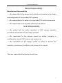
Manufacturer Responsibility
——Be responsible for the danger which should be eliminated on the design
and configuration of the provided CNC systems
——Be responsible for the safety of the provided CNC and its accessories
——Be responsible for the provided information and advice
User Responsibility
——Be trained with the safety operation of CNC system operation
procedures and familiar with the safety operation.
——Be responsible for the dangers caused by adding, changing or
modifying the original CNC systems and accessories.
——Be responsible for the danger caused by failing to observe the
operation, maintenance, installation and storage in the manual.
This user manual shall be kept by the end user.
V
GSK990MC Drilling and Milling CNC System
VI
PLC, Installation and Co
onnection
Us
ser Manual
VII
GSK990MC Drilling and Milling CNC System
PLC, Installation and Connection
User Manual
Safety responsibility
Manufacturer Responsibility
——Be responsible for the danger which should be eliminated on the design
and configuration of the provided CNC systems.
——Be responsible for the safety of the provided CNC and its accessories
——Be responsible for the provided information and advice.
User Responsibility
——Be trained with the safety operation of CNC system operation
procedures and familiar with the safety operation.
——Be responsible for the dangers caused by adding, changing or
modifying the original CNC systems and accessories.
——Be responsible for the danger caused by failing to observe the
operation, maintenance, installation and storage in the manual.
This user manual shall be kept by the end user.
Thank you for your kind support when you are using the products of
Guangzhou CNC Equipment Co., Ltd.
VIII
Contents
CONTENS
Ⅰ
PROGRAMMING ............................................................................. 1
CHAPTER 1 SEQUENCE PROGRAM CREATING PROCESS ................................................... 3
1.1
1.2
1.3
1.4
1.5
GSK990MC PLC Specification ..................................................................................... 3
What is a Sequence Program ....................................................................................... 3
Distribution Window (Step 1) ...................................................................................... 3
Ladder Diagram Programming (Step 2) .................................................................... 4
Sequence Programming Debugging (Step 3) .......................................................... 4
CHAPTER 2 SEQUENCE PROGRAM ...................................................................................... 5
2.1
2.2
2.3
2.4
2.5
Performance Process of Sequence Programming .................................................. 5
The Performance of the Cycle .................................................................................... 6
The Priority Sequence of the Performance (the 1st Level, the 2nd level) ........... 6
Sequence Programming Structure............................................................................. 7
The Treatment of the Input/Output Signal................................................................. 7
2.5.1 Input Signal Treatment .................................................................................... 8
2.5.2 The Treatment of the Output Signal ............................................................. 8
2.5.3 The Distinguish of the Signal State Between the 1st Level and the 2nd
Level Program............................................................................................................................ 9
2.6 Interlocking ...................................................................................................................... 9
CHAPTER 3 PLC ADRRESS ............................................................................................... 11
3.1
3.2
3.3
3.4
3.5
3.6
3.7
3.8
3.9
3.10
3.11
3.12
3.13
3.14
Machine → PLC Address(X) .................................................................................11
3.1.1 X Address on the I/O Input ............................................................................11
3.1.2 X Address on the MDI Panel .........................................................................11
PLC → Address of the Machine Tool Side(Y) ................................................... 12
3.2.1 Address on the I/O Output ........................................................................... 12
3.2.2 Y Address on the MDI Panel ........................................................................ 12
PLC→CNC Address(G) .......................................................................................... 13
CNC→PLC Address (F)......................................................................................... 13
Internal Replay Address(R) .................................................................................... 13
Nonvolatile Relay Address(K) ................................................................................ 14
Information Display Request Address(A)............................................................. 15
Counter Timer(C) ..................................................................................................... 15
Counter Preset Value Address(DC) ...................................................................... 15
Timer Address(T) ................................................................................................... 15
Presetting Value Address of the Timer(DT) ....................................................... 15
Data Table Address(D) ......................................................................................... 15
Label Address(L) ................................................................................................... 15
Subprogram Number(P) ....................................................................................... 16
CHAPTER 4 PLC BASIC CODES ........................................................................................ 17
4.1
4.2
4.3
4.4
RD, RD.NOT, WRT, WRT.NOT Code ........................................................................ 17
AND, AND.NOT Code .................................................................................................. 18
OR, OR.NOT Code....................................................................................................... 18
OR. STK Code .............................................................................................................. 19
IX
GSK990MC Drilling and Milling CNC
C
System
4.5
PLC, Installation and Co
onnection
Us
ser Manual
AND.STK
K Code ................................................................................................................ 19
CHAPTE
ER 5 PLC FUNCTIONA
AL CODE .................................................................................... 21
5.1
5.2
5.3
5.4
5.5
5.6
5.7
5.8
5.9
5.10
0
5.11
1
5.12
2
5.13
3
5.14
4
5.15
5
5.16
6
5.17
7
5.18
8
5.19
9
5.20
0
5.21
5.22
2
5.23
3
5.24
4
5.25
5
5.26
6
5.27
7
5.28
8
5.29
9
5.30
0
5.31
2
5.32
5.33
3
5.34
4
5.35
5
END1(1
1st Level Sequence Pro
ogram End)
) .............................................................. 21
nd
END2(2
2 Level Se
equence Pro
ogram End) ............................................................. 21
CALL(C
Call Subprog
gram) ............................................................................................ 22
CALLU(
(Unconditio
onal Subprogram Call) ............................................................... 22
SP(Sub
bprogram) ......................................................................................................... 22
SPE(Su
ubprogram End)
E
.............................................................................................. 23
SET(Se
et) ...................................................................................................................... 23
RST(Re
eset) .................................................................................................................. 24
JMPB(L
Label Jump) ..................................................................................................... 24
LBL(La
abel) ................................................................................................................. 24
TMR(T
Timer) ............................................................................................................... 25
TMRB(
(Fixed Time
er) .................................................................................................. 26
TMRC(Timer) ............................................................................................................ 26
CTR(B
Binary Coun
nter) ............................................................................................... 27
DEC(B
Binary Deco
ode) ............................................................................................... 28
COD(B
Binary Code
e Conversio
on) ............................................................................. 29
COM (C
Common Lin
ne Control) ....................
.
................................................................. 30
COME (Common
(
L
Line
Controll End) .......................................................................... 30
ROT(B
Binary Rotation Control) ............................................................................... 30
SFT(S
Shift Registe
er) .................................................................................................. 32
DIFU(R
Rising Edge
e Check)....................................................................................... 33
DIFD(F
Falling Edge Check) ....................
.
................................................................. 34
COMP(Binary Co
omparison) ................................................................................... 34
COIN(Coincidencce Check) .................................................................................... 35
MOVN(Transfer of
o Data) ......................................................................................... 35
MOVB(Transfer of
o One Byte) ................................................................................ 36
MOVW(Transfer of
o Two-Byte
e) ............................................................................... 36
XMOV(Binary Ind
dex Modifierr Data Trans
sfer) ...................................................... 37
DSCH (Binary Da
ata Search)
) ................................................................................. 38
ADD(B
Binary Addittion) ............................................................................................... 39
SUB(B
Binary Subtrraction) ......................................................................................... 39
ANDF(
(Functional And)............................................................................................. 40
ORF(F
Functional Or)
O
................................................................................................. 41
NOT(L
Logical Not)
) ..................................................................................................... 42
EOR(E
Exclusive orr) .................................................................................................... 43
CHAPTE
ER 6 LADDER WRITING
G LIMIT ...................................................................................... 45
Ⅱ
OP
PERATIO
ON ..................................................................................... 47
CHAPTE
ER 1 PLC WINDOW DISPLAY ...................................................................................... 49
1.1
1.2
X
Automatic Operation
n when GSK
K990MC PL
LC Power on .......................................... 49
ndow Displa
ay ..................................................................................................... 49
INFO Win
1.2.1 INFO Windo
ow .................................................................................................... 49
Contents
1.2.2
1.2.3
1.2.4
1.2.5
PLCGRA Window .......................................................................................... 50
PLCPAR Window ........................................................................................... 51
PLCDGN Window .......................................................................................... 51
PLCTRACE Window ..................................................................................... 52
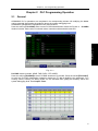
CHAPTER 2 PLC PROGRAMMING OPERATION.................................................................. 55
2.1
2.2
2.3
2.4
2.5
2.6
2.7
General ........................................................................................................................... 55
Basic Code .................................................................................................................... 56
Ladder Operation Explanation .................................................................................... 57
Function Code ............................................................................................................... 59
Instruction List ............................................................................................................... 59
Edit Instruction .............................................................................................................. 60
PLC Operation Step ..................................................................................................... 61
CHAPTER 3 PLC ADDRESS, PARAMETER SETTING ......................................................... 63
3.1
3.2
3.3
3.4
3.5
Nonvolatile/Hold Relay................................................................................................. 63
Timer ............................................................................................................................... 64
Data List ......................................................................................................................... 65
Counter ........................................................................................................................... 65
M Function Corresponding to F Address .................................................................. 66
CHAPTER 4 INSTRUCTIONS OF THE LADDER DIAGRAM EDIT SOFTWARE ........................ 69
4.1
4.2
4.3
III
Summary ........................................................................................................................ 69
Software Introduction ................................................................................................... 69
4.2.1 Software Start................................................................................................. 69
4.2.2 Function Introduction..................................................................................... 69
Software Operation ...................................................................................................... 70
4.3.1 Toolbar ............................................................................................................. 70
4.3.2 Selecting a Figure .......................................................................................... 71
4.3.3 Editing a Figure .............................................................................................. 72
4.3.4 Ladder Diagram Note .................................................................................... 73
4.3.5 Export .............................................................................................................. 74
FUNCTION ..................................................................................... 77
CHAPTER 1 CONTROLLED AXIS ......................................................................................... 79
1.1
1.2
Output Signal of Controllable Axis ............................................................................. 79
Servo Ready Signal...................................................................................................... 79
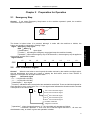
CHAPTER 2 PREPARATION FOR OPERATION ..................................................................... 81
2.1
2.2
2.3
2.4
2.5
Emergency Stop ........................................................................................................... 81
CNC Overtravel Signal................................................................................................. 81
Alarm Signal .................................................................................................................. 82
Operation Mode Selection ........................................................................................... 82
Status Output Signal .................................................................................................... 82
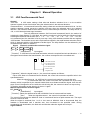
CHAPTER 3 MANUAL OPERATION ..................................................................................... 85
3.1
3.2
JOG Feed/Incremental Feed ...................................................................................... 85
MPG / Step Feed .......................................................................................................... 86
CHAPTER 4 REFERENCE POINT RETURN .......................................................................... 87
4.1
4.2
4.3
Manual Reference Point Return ................................................................................. 87
Reference Point Return Check Signal....................................................................... 87
Area Check Signal ........................................................................................................ 88
XI
GSK990MC Drilling and Milling CNC
C
System
PLC, Installation and Co
onnection
Us
ser Manual
CHAPTE
ER 5 AUTO
OMATIC OPE
ERATION ..................................................................................... 91
5.1
5.2
5.3
5.4
5.5
Cycle Sta
art/Feed Ho
old ..................................................................................................... 91
Reset................................................................................................................................... 92
Testing a Program ............................................................................................................ 93
M
Tool Lock ............................................................................................ 93
5.3.1 Machine
5.3.2 Dry
D Run .............................................................................................................. 93
5.3.3 Single
S
Blockk ....................................................................................................... 94
Optional Block Skip ......................................................................................................... 94
Program Restart ............................................................................................................... 95
CHAPTE
ER 6 FEEDRATE CONT
TROL .......................................................................................... 97
6.1
6.2
6.3
Rapid Tra
averse Rate
e ....................................................................................................... 97
Feedrate Override ............................................................................................................ 97
Override Cancel ............................................................................................................... 97
CHAPTE
ER 7 MISCE
ELLANEOUS
S FUNCTION
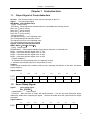
N .............................................................................. 99
7.1
7.2
7.3
7.4
M code Miscellaneo
M
us Function
n ................................................................................... 99
S Code Miscellaneo
M
us Function
n ................................................................................... 99
T Code Miscellaneo
M
us Function
n ................................................................................. 101
Miscella
aneous Function Lock ..................................................................................... 103
CHAPTE
ER 8 SPIND
DLE SPEED FUNCTION ...................
.
........................................................... 105
8.1
8.2
Spindle Speed
S
Conttrol Mode ....................................................................................... 105
8.1.1 Gear
G
Spindle .................................................................................................... 105
8.1.2 Analog
A
Spin
ndle ................................................................................................ 105
Rigid tap
pping ................................................................................................................. 106
CHAPTE
ER 9 PROG
GRAMMING CODE ....................................................................................... 109
9.1
9.2
Custom Macro
M
Program ................................................................................................ 109
Canned Cycle
C
................................................................................................................. 110
CHAPTE
ER 10 DISP
PLAY/SET.................................................................................................... 113
10.1
2
10.2
10.3
3
Clock Function ............................................................................................................. 113
Displayiing Operatio
on History ..................................................................................... 113
Help Function ............................................................................................................... 113
CHAPTE
ER 11 MEA
ASUREMENT
T ............................................................................................... 115
CHAPTE
ER 12 PAN
NEL LOCKED
D SETTING ...................
.
........................................................... 117
Ⅳ
INSTALLAT
ATION AN
ND CONN
NECTION
N ............................................ 123
CHAPTE
ER 1 SYSTE
EM STRUCT
TURE AND INSTALLATIO
N
ON ...................................................... 125
1.1
1.2
1.3
1.4
System Composition
C
n ..................................................................................................... 125
System In
nstallation & Connectio
on .............................................................................. 125
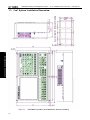
CNC Sysstem Installa
ation Dimen
nsion .......................................................................... 126
Additiona
al Panel ............................................................................................................. 127
CHAPTE
ER 2 DEVIC
CE CONNEC
CTION ........................................................................................ 129
2.1
2.2
XII
CNC Exte
ernal Conne
ection ............................................................................................ 129
2.1.1 Window
W
Layyout ................................................................................................ 129
2.1.2 Pulse
P
Servo
o Connectio
on Diagram ............................................................... 130
2.1.3 Bus
B Servo Connection
C
Diagram .................................................................. 131
Connectio
on between
n the System
m and the Drive
D
Unit............................................... 131
2.2.1 System
S
Win
ndow Diagra
am ............................................................................. 132
Contents
2.3
2.4
2.5
2.6
2.2.2 Window Signal Diagram ............................................................................. 132
2.2.3 Signal Explanation ....................................................................................... 132
2.2.4 Cable Connection Diagram ........................................................................ 134
2.2.5 GSK-LINK Cable Connection Drawing ..................................................... 136
RS232(XS9) Standard Serial Window..................................................................... 138
Connection between MPG and Handhold Unit ...................................................... 139
2.4.1 Window Signal Diagram ............................................................................. 139
2.4.2 Window Signal Explanation ....................................................................... 139
Connection of Spindle Unit ........................................................................................ 141
2.5.1 Window Signal Diagram ............................................................................. 141
2.5.2 Interface Signal Explanation ...................................................................... 142
2.5.3 Cable Connection Diagram ........................................................................ 142
2.5.4
GSK-Link Cable Diagram ......................................................................... 144
System Power Supply Window................................................................................. 147
CHAPTER 3 MACHINE CONTROL I/O WINDOW ................................................................ 149
3.1
3.2
3.3
Window Signal Diagram ............................................................................................ 149
Input Interface ............................................................................................................. 149
3.2.1 Input Interface Circuit .................................................................................. 149
3.2.2 Handhold Unit’s Interface Circuit ............................................................... 150
3.2.3 Interface Definition of the Input Signals ................................................... 150
Interface Output .......................................................................................................... 151
3.3.1 Circuit of Output Interface .......................................................................... 151
3.3.2 Definitions of the Output Signal Interfaces .............................................. 152
CHAPTER 4 MACHINE DEBUGGING .................................................................................. 155
4.1
4.2
4.3
4.4
4.5
4.6
4.7
4.8
4.9
4.10
4.11
4.12
4.13
4.14
4.15
4.16
4.17
Debug Preparation ..................................................................................................... 155
System Power-on ....................................................................................................... 155
Emergency Stop and Limit ........................................................................................ 155
Gear Ratio Regulation ............................................................................................... 157
Backlash Compensation ............................................................................................ 158
Settings Relevant to the Drive Unit .......................................................................... 159
The Machine Screw Pitch Compensation ............................................................... 160
Mechanical Zero Return (Mechanical zero Return) .............................................. 168
The Spindle Rotation (CW/CCW) Input/Output Signal Control ........................... 172
The Spindle Gear Change Control ........................................................................ 173
The External Cycle Start and Feed Hold .............................................................. 174
External Edit Lock and External Operation Panel Lock...................................... 175
Cooling, Lubricating,Chip Removal Control ...................................................... 176
Setting Related Feedrate ........................................................................................ 176
Setting Related to Tapping ...................................................................................... 178
Setting the Relative 4th Axis .................................................................................... 179
Setting Related to the Bus Servo ........................................................................... 180
APPENDIX .......................................................................................... 185
APPENDIX 1 LADDER CONFIGURATION FILE FORMAT .................................................... 187
1. F Signals and Meanings of M Code M00---M99 ............................................. 187
2. “%” that Ccupies a Line Exclusively Means the End of M Code Information
Storage. .................................................................................................................................. 187
3. The Codes and Meanings of X Signal X0.0-X6.7 ........................................... 187
4. The Codes and Meaning of Y Signal Y0.0---Y5.7 ........................................... 187
XIII
GSK990MC Drilling and Milling CNC
C
System
PLC, Installation and Co
onnection
Us
ser Manual
5. The Codes
C
and Meanings
M
o K Signal Y6.0---Y63.
of
Y
7 ........................................ 187
6. The Codes
C
and Meanings
M
o A Signal A0.0-A31.7A
of
A
A ........................................ 187
7. End //
/ End Sign ........................................................................................................ 188
XIV
Ⅰ
Programming
Ⅰ Programming
1
GSK990MC Drilling and Milling CNC System
Ⅰ Programming
2
PLC, Installlation and Co
onnection
Us
ser Manual
Chapter 1 Sequence Program Creating Process
Chapter 1
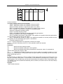
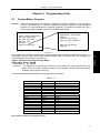
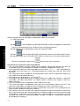
1.1
Sequence Program Creating Process
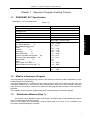
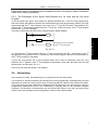
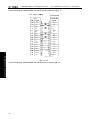
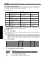
GSK990MC PLC Specification
GSK990MC
PLC is shown below:
Table 1-1-1
Specification
GSK990MC
Programming language
Ladder
Program level
The 1st level program execution cycle
2
Basis code average treatment time
5μs
Programming capacity
4700 steps
Code
Basis code + function code
Nonvolatile memory area
Timer
(T)
Counter
(C)
Data base
(D)
Nonvolatile relay
(K)
Counter prevalue data register (DC)
Timer prevalue data register (DT)
Subprogram
(P)
Mark
(L)
Input signal of NC side(F)
Signal outputs to the NC side (G)
I/O module
(Y)
1.2
(X)
8ms
Ⅰ Programming
Internal relay
(R)
(A)
PLC alarm detection
PLC
0~511 ( byte )
0~31( byte )
0~127 (word)
0~127 (word)
0~255 (word)
0~63 ( byte )
0~127(word)
0~127(word)
0~99
0~99
0~63( byte )
0~63( byte )
0~63 ( byte )
0~47 ( byte )
What is a Sequence Program
The programming is performed a logic control to the machine tool and its relative equipments, which
is called sequence programming.
After the programming is converted into some kind of format, CPU can be performed the code and
calculation treatment for it, and its fruits can be memorized to RAM. CPU can be rapidly read each
code stored in the memory, which can be performed the programming according to the calculation
operation.
The compiling of the sequence programming starts with developing of the ladder diagram.
1.3
Distribution Window (Step 1)
The window can be distributed after confirming the controlled object and calculating the points
of the corresponding input/output signal.
Refer to the Chapter Four Input/output window signal table in the part of the Installation and
Connection when distributing the window.
3
GSK990MC Drilling and Milling CNC
C
System
1.4
PLC, Installlation and Co
onnection
Us
ser Manual
La
adder Diagram Programm
P
ming (Ste
ep 2)
GSK990MC
C ladder dia
agram is not permitted by an on-line
e modification but is edit by the softw
ware Lad
Edit.exe on
n the compu
uter. The control operation required
d by the machine tool ccan be expre
essed by
the ladder diagram. The functionss, such as the
t
timer an
nd counter, can not be expressed by relay
w
can be
e indicated by
b the speciffied function code symbols.
symbols, which
The compiled ladder diiagram shou
uld be upgra
aded to the system.
s
1.5
Se
equence
e Program
mming Debuggin
D
ng (Step 3)
Ⅰ Programming
The sequen
nce program
mming can be
b debugged
d using the following
f
me
ethods:
1) Debugging with emu
ulator
ne tool can be
b replaced by an emullator (it composes of the
e lights and switches). The
T input
The machin
signal state
e of the macchine tool ca
an be expresssed by the ON or OFF
F of the switcches; and th
he output
signal state
e can be indicated by the ON or OFF of the ligh
ht.
2) Debugging with actu
ual operation
n
t actual machine
m
tool.. It is better to
t prepare th
he precautio
ons before d
debugging, due
d to an
Debug on the
unexpected
d behavior may
m occur.
4
Chapter 2 Sequence Program
Chapter 2
Sequence Program
The operating principle is different with the common relay, because the PLC sequence controlling is
carried out by the ladder digram Lad Edit.exe compiling.
And therefore, it is better to thoroughly understand the sequence controlling principle when
designing the PLC sequence programming.
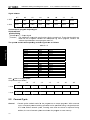
2.1
Performance Process of Sequence Programming
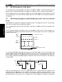
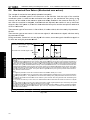
In the general relay controlling circuits, each of them can be simultaneously operated. When the relay
A is operated in the following figure, the replay D and E can be operated (when the contactor A and B
are closed) at the same. Each replay in the PLC sequence control is operated in turn. The relay D is
operated before relay A, and then the relay E operates (refer to the following figure). Namely, each
relay is operated based upon the sequence of the ladder diagram (compiling sequence).
A
B
Ⅰ Programming
D
A
C
E
Fig. 2.1 (a) Circuit illustration
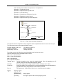
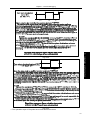
The differences between the relay circuit and PLC programming operation are shown below in the Fig.
2.1 (b) and Fig. 2.1 (c).
A
C
B
A
C
Fig. 2.1 (b)
A
C
A
C
B
Fig. 2.1 (c)
(1) Relay circuit
Both Fig. 2.1 (b) and Fig. 2.1 (c) are shared a same operation. B and C are switched on after A is
turned on. B is cut off after C is ON.
(2) PLC program
A same relay is shared a same circuit, refer to the Fig. 2.1 (b); B and C are switched on after A is
turned on. B is cut off after one cycle of the PLC program is performed. In the Fig. 2.1 (c), C is ON
instead of B, after C is turned on.
5
GSK990MC Drilling and Milling CNC
C
System
2.2
PLC, Installlation and Co
onnection
Us
ser Manual
Th
he Perfo
ormance of the Cy
ycle
PLC perforrms from th
he beginning
g to the en
nd of the la
adder diagra
am. It performs again from
f
the
beginning of
o the ladderr diagram affter this diag
gram is perfo
ormed, whicch is called ccycle perform
mance.
mance time from the be
eginning to th
he end of the ladder dia
agram is abb
breviated as a period
The perform
of a cycle treatment.
t
T shorter of
The
o the treatm
ment period is, the stron
nger of the rresponse ca
apacity of
the signal iss.
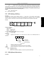
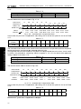
2.3
Th
he Prioriity Seque
ence of the
t Perfo
ormance (the 1st Level, th
he 2nd
level)
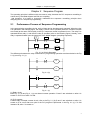
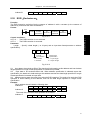
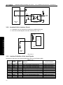
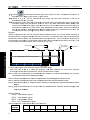
GSK990MC
C PLC progrram are com
mposed of tw
wo parts: the
e 1st level pro
ogram and tthe 2nd level program,
which are inconsistent with the perrformance period.
p
Ⅰ Programming
el program performs on
nce each 8m
ms, which ca
an be treate
ed some fast corresponding and
The 1st leve
short pulse
e.
ogram perfo
orms once each
e
8*nms.. N is the pa
artition value
e of the 2nd level progra
am. PLC
The 2nd pro
nd
nd
n
may divide the 2 leve
el program in
nto N parts when
w
the 2 level program is execcuted. It is pe
erformed
one part for each 8ms.
st
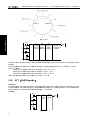
Th
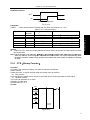
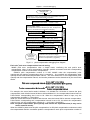
he 1
le
evel
pro
ogram
st
Specify the 1 EOB
END1
Partition 1
Partition 2
The
e 2nd
le
evel
prog
gram
Partition n
Speciffy the 2nd EOB
E
END2
Fig. 2-3-1
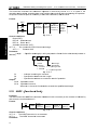
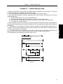
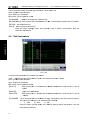
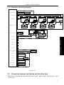
C is separattely performed in the PL
LC-AVR SC
CM. The 1mss of each 8m
ms is the
PLC in the GSK990MC
ation time fo
or reading the
t
PLC datta from the CNC. The 5ms is thatt the PLC gains
g
the
communica
system con
ntrol signal (F.
( X), and uploads
u
the control result data (G, Y paramete
er) external port I/O.
PLC is alw
ways perform
med the ladd
der diagram calculation other than the interruption of the response
r
exchange data.
d
The 1sts
level
nd
The
e2
lev
vel
8ms
8ms
Partition
n1
P
Partition
2
8ms
Partition n
Fig. 2-3-2
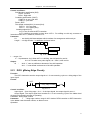
When the last partition
n value of the
t
2nd leve
el program of
o the n is performed,
p
tthe program
m is then
executed from
f
the be
eginning of the progra
am. In this case, when
n the partittion value is n, the
performancce time of on
ne cycle is 8*n ms. The 1st level prog
gram performs once each 8ms; the 2nd level
program pe
erforms once each 8*n ms. If its ste
eps of the 1st level prog
gram is incre
eased, and therefore
t
6
Chapter 2 Sequence Program
the steps of the 2nd level program within 8ms should be reduced correspondingly; the partition value
may be increased, and the treatment time of the overall program will be longer. So, the compiling of
the 1st level program should be shorter.
2.4
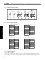
Sequence Programming Structure
The ladder diagram is compiled with sequence in the traditional PLC. It owns the following
advantages in the ladder diagram language allowing the structured programming:
1. The program is easy to comprehend and compile.
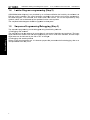
2. It is more convenient to find the faults during the programming.
3. It is easy to find some reasons when the operation malfunction occurs.
The methods of the main structure programming are shown below:
1) Sub-program
The subprogram is regarded as a treatment unit based on the ladder diagram.
Ⅰ Programming
A
C
B
Task A
A
.
.
.
.
Task B
C
Fig. 2-4-1
2) Nesting
One subprogram can be performed the task by calling another one.
Main program
Task A
Subprogram 1
Subprogram 2
Task A1
Task A11
Task A12
Task B
Task An
Fig. 2-4-2
3) Conditional branch
The main program is performed circularly, and checks whether its conditions are suitable. The
corresponding subprograms are performed under these conditions, vice versa.
Fig. 2-4-3
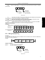
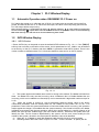
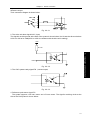
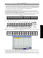
2.5
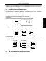
The Treatment of the Input/Output Signal
The treatment of the input signal:
7
GSK990MC Drilling and Milling CNC System
CNC
PLC, Installation and Connection
User Manual
CNC—PLC
Shared register
The 1st level
program
Latched at the
beginning of the
2nd level
nd
The 2
program input
signal latch
The 2nd level
program
Machine tool
input register
8ms
IO terminal
Ⅰ Programming
Fig. 2-5-1
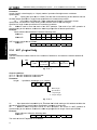
The treatment of the output signal:
CNC
PLC
CNC—PLC
st
The 1
level
program
Shared register
The 2nd
level
program
Machine tool
input register
8ms
IO terminal
Fig. 2-5-2
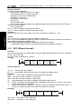
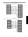
2.5.1
Input Signal Treatment
(1) NC input register
The NC input signals from the NC are memorized into the NC input register, which are transferred to
PLC each 8ms. The 1st level program performs the corresponding treatment using state of these
signals.
(2) Machine tool input register
The machine tool input register is scanned and memorized its input signal from the machine each
8ms. The 1st level program is also performed the corresponding treatment by using this signals
directly.
(3) The 2nd level program input register
The 2nd level program input signal register is also called the 2nd level program synchronic input signal
register. Wherein, the stored input signal is treated by the 2nd level program. This signal state in the
register is synchronic with the 2nd level one.
The signals both in the NC and machine tool input register can be locked to the 2nd level program
input latch, as long as the 2nd level program performs. The signal state in this latch keeps invariable
during the performance of the 2nd level program.
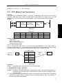
2.5.2
The Treatment of the Output Signal
(1) NC output register
The output signal transfers to the NC output register from the PLC each 8ms.
(2) Machine tool output register
The signal memorized in the machine tool output register conveys to the machine tool each 8ms.
Note: The signal states, such as the NC input register, NC output register, machine input register and machine
8
Chapter 2 Sequence Program
output register, which can be displayed by the self-diagnosis function. The diagnosis number is the address
number in the sequence programming.
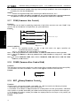
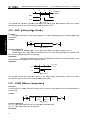
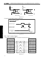
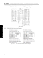
2.5.3 The Distinguish of the Signal State Between the 1st Level and the 2nd Level
Program
As for the same input signal, their states may different between the 1st and 2nd level programming,
that is the reason that different registers are used between two levels programming. Namely, the input
signal used with the 2nd level program is the one of the 1st level who is locked. And therefore, the
signal in the 2nd level program is later than the 1st level one. At the worst case, one 2nd level program
performance cycle can be lagged.
It is better to remember this point when programming the ladder diagram.
A
B
C
It belongs to the 2 nd partition
of the 2 nd level program
Fig. 2-5-3-1
A=1 performs the 1st level program when the 1st 8ms is performed, then B=1. And therefore, the 2nd
level program is performed, the A=1 is latched to the 2nd level program, and then the first partition of
the 2nd level program is completed.
A turns into 0 to perform the 1st level program when the 2nd 8ms is performed, then B=0. And
therefore, the 2nd partition of the 2nd level program is performed; in this case, the state of the A is still
latched as the one last time. So, C=1.
In this way, the state both B and C are different.
2.6
Interlocking
In the sequence control, the interlocking is very important from the safety issue.
It is necessary to use the interlocking in the sequence control programming. Simultaneously, the hard
interlocking is used in the relay control circuit of the strong electric cabinet of the machine tool sides.
This is the reason that the interlocking is disabled when the hardware of the performance sequence
programming malfunctions, even if the interlocking is logically used in the sequence program
(software). And therefore, the interlocking can be ensured the safety for the user, and prevent the
machine tool from damaging in the strong electric cabinet of the machine sides.
9
Ⅰ Programming
A
.
.
.
.
END1
.
.
.
.
GSK990MC Drilling and Milling CNC System
Ⅰ Programming
10
PLC, Installlation and Co
onnection
Us
ser Manual
Chapter 3 PLC Adrress
Chapter 3
PLC Adrress
Address distinguishes signal. Different address is separately corresponding to the I/O signal at the
side of the machine tool, the I/O signal at the side of the CNC, the internal relay, the counter, the timer,
the nonvolatile relay and the data list. Each address is composed of the address number and bit
number, and its number is as shown below:
Address number rules:
Address number consists of address type, address number and bit number.
X 000 . 6
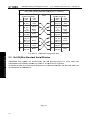
3.1
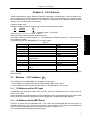
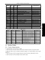
Machine → PLC Address(X)
The X address of the GSK990MC PLC composes of two types:
1. The X address is assorted with the I/O input terminal, XS40, XS41, XS42.
2. The X address is assorted with the input button on the MDI panel of the system.
3.1.1
X Address on the I/O Input
48 addresses are defined as INT8U from X0 to X5, which are distributed on the I/O input terminal,
XS40, XS41, XS42.
Users can define the signal significance of the X address of the I/O ports based upon the actual cases,
which can be connected the machine tool and compiled the corresponding ladder diagram.
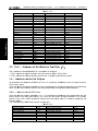
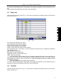
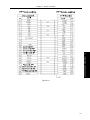
3.1.2
X Address on the MDI Panel
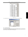
There are 11 bytes from the addresses X20 ~ X30, which are corresponded with the button input on
the MDI panel one by one. User can not modify its signal definition. The buttons on the MDI panel
should be firstly responded by CNC, and then conveys the X signal to PLC.
The corresponding relationships are shown below:
11
Ⅰ Programming
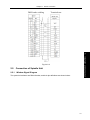
Type Address number Bit number
Address type: X, Y, R, F, G, K, A, D, C and T
Address number: Decimal number means one byte.
Bit number: Octonary number system, 0~7 are separately indicated the bytes (0~7 bits) in the front
of the address number.
The address type of the GSK990MC PLC is shown below:
Table 3-1
Address explanation
Length
Address
X
INT8U
MT→PLC(64 bytes)
Y
INT8U
PLC→MT(48 bytes)
F
INT8U
CNC→PLC(64 bytes)
G
INT8U
PLC→CNC(64 bytes)
R
INT8U
Intermediate relay (512 bytes)
INT16U
D
Data register (0~255)
DC
The data register of the counter INT16U
preset value
INT16U
C
Counter (0~127)
A
INT8U
PLC alarm detection
INT16U
T
Timer (0~127)
DT
The data register of the timer preset INT16U
value
K
INT8U
Nonvolatile relay(64 bytes)
INT8U data type is 8-bit character type without symbol, INT16U data type is 16-bit integral type
without symbol.
GSK990MC Drilling and Milling CNC
C
System
Butto
on input
Ⅰ Programming
Edit mode
m
A uto
o mode
MDI mode
m
Zero return mode
Step mode
Manu
ual mode
MPG
G mode
DNC mode
Skip
Single
Dry run
Misce
ellaneous lockk
Mach
hine lock
Optio
onal stop
Progrram restart
Light
Spind
dle rotation CC
CW
Spind
dle stop
Spind
dle rotation CW
W
Spind
dle JOG
Lubricating
Cooliing
Chip removal
Emerrgency stop
Cycle
e start
Feed
d hold
Rapid
d switch
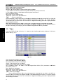
3.2
PLC, Installlation and Co
onnection
Ta
able 3-1-2-1
PL
LC address Button input
X20
0.0
Rapid F0
X20
0.1
Rapid F25%
%
X20
0.2
Rapid F50%
%
X20
0.3
Rapid F1000%
X20
0.4
X20
0.5
X20
0.6
X20
0.7
X21.0
X21.1
X21.2
X21.3
X21.4
X21.5
X21.6
X21.7
X22
2.0
X22
2.1
X22
2.2
X22
2.6
X23
3.0
X23
3.1
X23
3.2
X23
3.5
X23
3.6
X23
3.7
X24
4.7
F0% 0.001
F25% 0.01
F50% 0.1
F100% 1
Manual fee
ed axis +1st
Manual fee
ed axis +2ndd
Manual fee
ed axis +3rd
Manual fee
ed axis +Nth
Manual fee
ed axis -1st
Manual fee
ed axis -2nd
Manual fee
ed axis -3rd
Manual fee
ed axis -Nth
Spindle orientation
Overtravel release
Spindle override SOV1
Spindle override SOV2
Spindle override SOV4
Feedrate ov
verride FOV1
Feedrate ov
verride FOV2
Feedrate ov
verride FOV4
Feedrate ov
verride FOV8
Feedrate ov
verride FOV16
6
Us
ser Manual
PLC ad
ddress
X25.0
X25.1
X25.2
X25.3
X26.0
X26.1
X26.2
X26.3
X27.0
X27.1
X27.2
X27.3
X28.0
X28.1
X28.2
X28.3
X29.0
X30.0
X31.0
X31.1
X31.2
X31.3
X31.4
X31.5
X31.6
X31.7
PL
LC → Add
dress of the Machine Too
ol Side(Y)
The Y addrress of the GSK990MC
G
PLC compo
oses of two types:
t
1. The Y ad
ddress is asssorted with the
t I/O input terminal, XS43,
X
XS44,, XS45.
2. The Y ad
ddress is asssorted with the
t input button on the MDI
M panel of
o the system
m.
3.2.1
Ad
ddress on
o the I/O
O Outputt
48 addressses are defin
ned as INT8
8U from Y0 to Y5, which
h are distrib
buted on the
e I/O output terminal,
XS43, XS4
43, XS45.
Users can define
d
the siignal significcance of the Y address of
o the I/O po
orts based up
pon the actu
ual cases,
which can be
b connecte
ed the machine tool and
d compiled th
he corresponding ladder diagram.
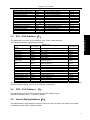
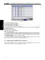
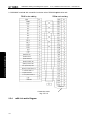
3.2.2
Y Address
A
on
n the MDI Panel
There are 8 bytes from
m the addressses Y12 ~ Y19 which these
t
addre
esses are co
orresponded with the
button inpu
ut on the MDI panel on
ne by one. User can no
ot modify itss signal deffinition. PLC
C system
reports to the CNC system keyb
board module after calculating, an
nd it is used
d for displa
aying the
gnal.
indicator sig
The corresponding rela
ationships off each prom
mpt light:
Ta
able 3-2-2-1
Keyboa
ard indicator ou
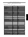
utput
Edit keyy indicator
Auto ke
ey indicator
MDI keyy indicator
Zero retturn key indica
ator
Step ke
ey indicator
Manual key indicator
MPG ke
ey indicator
DNC ke
ey indicator
12
PLC addresss
Y12.0
Y12.1
Y12.2
Y12.3
Y12.4
Y12.5
Y12.6
Y12.7
Keyboard indicator outp
put
Chip remo
oval indicator
Feedrate override canccel key indicato
or
Rapid swiitch indicator
0.1/50% indicator
Spidle orie
entation indica
ator
Magazine
e tool clamping
g tool indicator
Magazine
e tool change indicator
i
USER3 in
ndicator
PLC add
dress
Y15.0
Y15.1
Y15.2
Y15.5
Y15.7
Y16.5
Y16.6
Y16.7
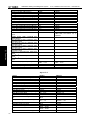
Chapter 3 PLC Adrress
Keyboard indicator output
Spindel rotation(CCW) indicator
Spindel rotation(CW) indicator
Spindel stop indicator
The 1st axis zero return indicator
The 2nd axis zero return indicator
The 3rd axis zero return indicator
Skip indicator
Single indicator
Drun run indicator
Miscellaneous lock indicator
Machine lock indicator
Machine light indicator
Lubricating indicator
Cooling indicator
3.3
PLC address
Y13.0
Y13.1
Y13.2
Y13.3
Y13.4
Y13.5
Y14.0
Y14.1
Y14.2
Y14.3
Y14.4
Y14.5
Y14.6
Y14.7
Keyboard indicator output
+the 1st axis key indicator
+ the 2nd axis key indicator
+ the 3rd axis key indicator
+ the 4th axis key indicator
- the 1st axis key indicator
- the 2nd axis key indicator
- the 3rd axis key indicator
-the 4th axis key indicator
Jog key indicator
Overtravel release indicator
Feed hold key indicator
Cycle start key indicator
Optional stop indicator
Program restart indicator
PLC address
Y17.0
Y17.1
Y17.2
Y17.3
Y18.0
Y18.1
Y18.2
Y18.3
Y18.7
Y19.0
Y19.1
Y19.2
Y19.4
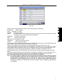
Y19.5
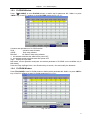
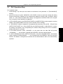
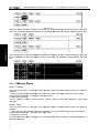
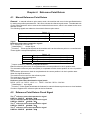
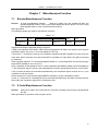
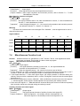
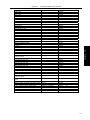
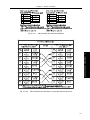
PLC→CNC Address(G)
Ⅰ Programming
The addresses from G0 to G63, its definition type: INT8U, totally 64 bytes.
The operation panel key signal is shown below:
Table 3-3-1
Operation panel
signal
Edit mode
Auto mode
MDI mode
Zero return mode
Step mode
Manual mode
MPG mode
key
PLC address
G20.0
G20.1
G20.2
G20.3
G20.4
G20.5
G20.6
DNC mode
G20.7
Skip
G21.0
Single
Dry run
Miscellaneous lock
Machine lock
Optional stop
Program restart
Spindle rotation CCW
Spindel stop
Spindle rotation CW
Spindle override cancel
Spindle jog
G21.1
G21.2
G21.3
G21.4
G21.5
G21.6
G22.0
G22.1
G22.2
G22.4
G22.6
Operation panel key signal
Lubricating
Cooling
Chip removal
Cycle start
Feed hold
Feedrate override cancel
Rapid switch
MPG/incremental feed movement amount’s
selection signal 1
MPG/incremental feed movement amount’s
selection signal 12
Manual feed axis +1st
Manual feed axis +2nd
Manual feed axis +3rd
Manual feed axis +Nth
Manual feed axis -1st
Manual feed axis -2nd
Manual feed axis -3rd
Manual feed axis -Nth
Spindle orientation
Overtravel release
PLC address
G23.0
G23.1
G23.2
G23.6
G23.7
G24.1
G24.7
G26.4
G26.5
G27.0
G27.1
G27.2
G27.3
G28.0
G28.1
G28.2
G28.3
G29.0
G30.0
G63 byte’s bit signal is used by the system interior. G63.0, G63.1, G63.2 is the separate system
interior’s response signal when M, S, T execution is completed.
3.4
CNC→PLC Address (F)
The addresses from F0 to F63 are defined as: INT8U, totally 64 bytes.
Refer to the Chapter Three Function for details.
3.5
Internal Replay Address(R)
The address area is reset when the system is turned on. R510 and R511 are used by the system.
Its definition type is: INT8U, totally 512 bytes.
13
GSK990MC Drilling and Milling CNC
C
System
Address
A
n
number
6
7
5
3
4
2
PLC, Installlation and Co
onnection
Us
ser Manual
1 0
R0
R relay area
R511
R
Ⅰ Programming
Fig.3-5-1
System prrogram adm
ministration area:
R510
et to 1 when PLC starts and restartss, which is ussed the sign
nal set by
The signal of R510.0 address is se
erformed oncce.
the initial usser. The R510.0 is reset to 0 after the ladder diagram is pe
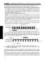
R511(Sysstem timer)
The following four signals can be used
u
for system timer:
7
6
5
4
3
2
1
0
R511
A
Always
cut off
o
A
Always
powe
er on
(104ms ON, 96mss OFF)
ms OFF)
(504ms ON, 496m
200ms perio
2
od
s
signal
1s period signal
Fig. 3-5-2
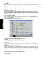
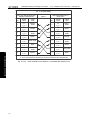
3.6
No
onvolatile
e Relay Address
A
(K)
This addresss area is ussed for nonvvolatile repla
ay and PLC parameter setting.
s
Thiss area is called
nonvolatile relay area, namely, the content inside the regis
ster will not lose
l
even if the system is turned
~K005 are used
u
by the system,
s
which is used to
o protect the
e PLC syste
em paramete
er, it is
off. K000~~
very convenient for use
er to control PLC in the CNC system
m.
8U, totally 64
4 bytes.
Its definition type: INT8
Address
number
7
6
5 4 3 2 1 0
K0
K1
K re
elay
are
ea
K63
Fig. 3-6-1
Note: When PLC address
s K005.2 =1, PLC
P
enters th
he debugging
g mode. All off the externall alarms are cancelled,
c
chine interlocking signals
s are then ca
ancelled, the
e tool-change
e code can n
not be performed. The
and the mac
parameter can
c be modified only when
n comprehen
nding the para
ameter, so th
hat the damag
ge in the mac
chine tool
or injury of the
t person may
m occur.
14
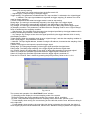
Chapter 3 PLC Adrress
3.7
Information Display Request Address(A)
This address area is reset when the system is turned on
Its definition type: INT8U, totally 32 bytes.
3.8
Counter Timer(C)
This area is used for placing the current count value of the counter. The data is reset after the system
is turned off.
Its definition type: 128 addresses.
3.9
Counter Preset Value Address(DC)
This address area is used for storing the counter preset, which is a nonvolatile storage area, that is,
the memorized content may not loose even the system is power off.
Its definition type: 128 addresses. The setting value of the DC is only read instead of writing.
3.10
Timer Address(T)
This address area is used for storing the current numerical value of the timer. The data initial is
presetting value after the system is power off. Current data is presetting value when it is set to 0.
Its definition type: 128 addresses
3.11
Presetting Value Address of the Timer(DT)
This address area is used for placing the timer preset value. This area is nonvolatile register area,
namely, the content inside the register will not lose even if the power of the system is turned off.
Its definition type: 128 addresses. The setting value of the DT is only read instead of writing.
3.12
Data Table Address(D)
The content inside the memory will not lose even if the power of the system is turned off.
Its definition type: totally 256 addresses. Among them, D240~247 are used by the system instead of
the user.
3.13
Label Address(L)
It is used to specify labels both skip object and the LBL code in the JMPB code.
15
Ⅰ Programming
Fig. 3-7-1
GSK990MC Drilling and Milling CNC
C
System
PLC, Installlation and Co
onnection
Us
ser Manual
Its ran
nge: 0~99
3.14
Subprogram Num
mber(P)
It is used to specify the called
d object subprogram number in the CALL code and the sub
bprogram
t SP code
e.
number in the
Its rang
ge: 0~99
Ⅰ Programming
16
Chapter 4 PLC Basic Codes
Chapter 4
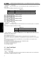
PLC Basic Codes
The design of the sequence program begins from the compiling of the ladder diagram. The ladder
diagram consists of relay contact and function code. The logic relationship in the ladder diagram
composes of sequence program. There are two methods of the sequence program input: one is that
the input method uses the mnemonic symbol language (The system is not temporarily supported the
PLC instruction code of the RD, AND and OR); the other one that is used the relay symbol. The
programming can be compiled using ladder diagram, and do not comprehend the PLC code based
upon the latter.
Actually, the sequence program inside the system can be converted into corresponding PLC code
even if it is input by the relay symbol.
The basis codes are commonly used codes when designing the sequence programming, which are
performed one-digit calculation.
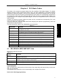
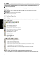
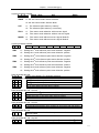
The basis instruction codes of the GSK990MC are shown below:
Table 4-1
Function
RD
WRT
Left shift one bit of the content of the register, the signal state specified
by address set to ST0
Left shift one bit of the content of the register, the signal state specified
by address is set to ST0 after its state is set to NOT.
Output the logic calculation result to the specified address
WRT.NOT
Output the logic calculation result after NOT to the specified address.
AND
Logic AND
AND.NOT
Logic AND after the specified state is set to NOT.
OR
Logic OR
OR.NOT
Logic OR after the specified state is set to NOT.
OR. STK
AND.STK
Right shift one bit of the stacked memory after ST0 and ST1 logic OR
Right shift one bit of the stacked memory after ST0 and ST1 logic AND
RD.NOT
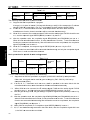
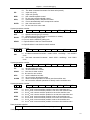
4.1
Ⅰ Programming
Code name
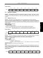
RD, RD.NOT, WRT, WRT.NOT Code
Mnemonic symbol and function
Table 4-1-1
Mnemonic
Function
symbol
RD
Left shift one bit of the content of the register, the signal state specified by
address is set to ST0.
RD.NOT
Left shift one bit of the content of the register, the signal state specified by
address is set to ST0 after it is set to NOT.
WRT
Output the logic calculation result to the specified address
WRT.NOT
Output the logic calculation result after NOT to the specified address
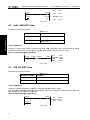
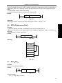
Code explanation
WRT and WRT.NOT codes are the coil drive code of the output relay and internal relay, but the input
relay can not be used.
The paratactic WRT instruction can be used multiply, but it outputs with multicoil .
Refer to the following programming:
17
GSK990MC Drilling and Milling CNC
C
System
PLC, Installlation and Co
onnection
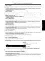
X002.1
Y003.7
7
()
F100.3
G120.0
0
()
RD
X002.1
WRT
Y003.7
Us
ser Manual
RD.NO
OT F100.3
WRT
G120.0
Fig. 4-1-1
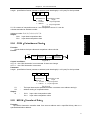
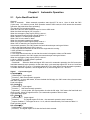
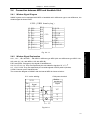
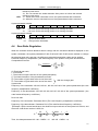
4.2
AN
ND, AND.NOT Cod
de
Mnemonic symbol and function
T
Table
4-2-1
c symbol
Mnemonic
Function
AND
Logic
L
AND
Ⅰ Programming
AND.N
NOT
Logic AND after the spe
ecified
state is NOT
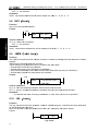
anation
Code expla
D, AND.NOT
T code. The
e numbers of
o series
Connect 1 contact witth series connection byy using AND
ained, and th
his code can
n be used for dozens of times.
connection contacts arre unconstra
he following
g programm
ming:
Refer to th
X002.1
F100.3
X008.6
Y003
3.7
()
RD
X002.1
AND.NO
OT F100.3
X008.6
AND
Y003.7
WRT
Fig. 4-2-1
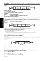
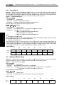
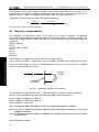
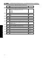
4.3
OR
R, OR.NO
OT Code
Mnemonic symbol and function
T
Table
4-3-1
monic symb
bol
Mnem
Functtion
OR
Logic OR
OR.N
NOT
Logic OR after the specified state
s
is NOT
T
Code expla
anation
h series conn
nection usin
ng the OR an
nd OR.NOT code.
Connect 1 contact with
OT is started
d from the sttep of this co
ode; it can be connected
d with seriess connection
n with the
OR, OR.NO
abovementtioned RD, RD.NOT
R
cod
de step.
Refer to th
he following
g programm
ming:
X002.1
7
Y003.7
()
F100.3
Fig. 4-3-1
18
RD
X002.1
OR.NOT F100.3
WRT
Y003.7
Chapter 4 PLC Basic Codes
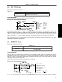
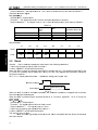
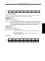
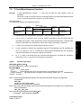
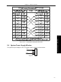
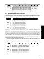
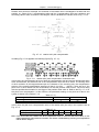
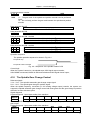
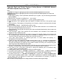
4.4
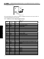
OR. STK Code
Mnemonic symbol and function
Table 4-4-1
Mnemonic symbol
OR. STK
Function
Right shift one bit of the stacked register after
ST0 and ST1 logic OR
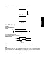
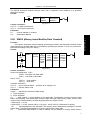
Code explanation
OR.STK code is the separate code without any address.
Refer to the following programming:
1
X 002.1 X 002.2
F 100.3
Y 003.7
( )
N ode N 1
F 100.6
O R .S T K
2
R 022.1
OR
X 002.1
X 002.2
F 100 .3
F100.6
R 022 .1
Y 003.7
Fig. 4-4-1
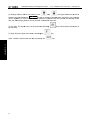
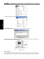
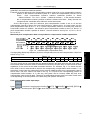
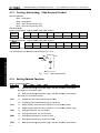
There are three branches ①, ② and ③ from the left bus to the node N1. The branches ① and ② are
series connection circuit block. When the series connection circuit block is performed between bus to
node or among the nodes, other than the first branch, use the RD code when the following branch is
ended. The branch ③ is not a series connection circuit block, which can be used by the OR code.
OR. STK and AND. STK are the code without operation component, which indicates the OR , AND
relationships between circuit blocks.
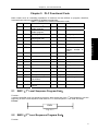
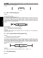
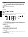
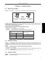
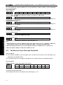
4.5
AND.STK Code
Mnemonic symbol and function
Table 4-5-1
Mnemonic symbol
Function
AND.STK
Right shift one bit of the stacked memory after ST0 and
ST1 logic AND
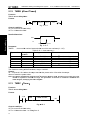
Code explanation
Use the AND. STK coded when the branch circuit (parallel circuit block) is connected with series
connection with the front of the circuit. The start of the branch is used RD, RD.NOT code. Use the
AND. STK code is connected with series connection with the front of the circuit after the series
connection circuit block is executed.
AND. STK code is the separate code without any address.
Refer to the following programming:
X 0 0 2 .1 R 1 0 0 .0 R 1 0 0 .3
Y 0 0 3 .7
( )
F 1 0 0 .3 G 0 0 3 .3 R 0 0 9 .7
X 0 1 1 .0
B lo c k
1
B lo c k
2
R D X 0 0 2 .1
O R .N O T F 1 0 0 .3
O R .N O T X 0 1 1 .0
R D R 1 0 0 .0
A N D .N O T R 1 0 0 .3
R D G 0 0 3 .3
A N D R 0 0 9 .7
O R .S T K
(1 )
A N D .S T K
(2 )
Fig. 4-5-1
As for the abovementioned ladder diagram and instruction table, ⑴OR.STK indicates parallel
19
Ⅰ Programming
3
RD
A N D .N O T
R D .N O T
AND
O R .S T K
OR
W RT
GSK990MC Drilling and Milling CNC
C
System
PLC, Installlation and Co
onnection
Us
ser Manual
connection of the serie
es connectio
on circuit block in the block
b
②, ⑵AND.STK e
expresses th
he series
connection between circuit block ① and ②.
Ⅰ Programming
20
Chapter 5 PLC Functional Code
Chapter 5
PLC Functional Code
Basic codes such as controlling operations of machine tool are difficult to program, therefore,
functional instructions are available to facilitate programming.
Table 5-1 (990MC PLC functional instruction code)
Code
Function
No.
Code
Function
No.
19
ROT
Binary rotation control
20
SFT
Register shift
21
DIFU
Rising edge check
22
DIFD
Failing edge check
SP
Unconditional
subprogram call
Subprogram
23
COMP
Binary comparison
6
SPE
End of subprogram
24
COIN
Coincidence check
7
SET
Set
25
MOVN
8
RST
Reset
26
MOVB
Transfer
of
an
arbitrary number of
bytes
Transfer of 1 byte
9
JMPB
Label jump
27
MOVW
Transfer of 2 bytes
10
LBL
Label
28
XMOV
Indexed data transfer
11
TMR
Timer
29
DSCH
Binary data search
12
TMRB
Fixed timer
30
ADD
Binary addition
13
TMRC
Timer
31
SUB
Binary subtraction
14
CTR
Binary meter
32
ANDF
Functional AND
15
DEC
Binary decoding
33
ORF
Functional OR
16
COD
34
NOT
Logical Negation
17
COM
Binary
code
conversion
Common line control
35
EOR
Exclusive OR
18
COME
END1
2
END2
3
CALL
4
CALLU
5
Ⅰ Programming
5.1
End of a 1st level
ladder program
End of a 2nd level
ladder program
Subprogram call
1
End of common line
control
END1(1st Level Sequence Program End)
Function:
It must be specified once in a sequence program, either at the end of the 1st level sequence, or at the
beginning of the 2nd level sequence when there is no 1st level sequence. It can write 500 steps.
Format:
END1
Fig. 5-1-1
5.2
END2(2nd Level Sequence Program End)
Function
21
GSK990MC Drilling and Milling CNC
C
System
PLC, Installlation and Co
onnection
Us
ser Manual
Specify at the
t end of 2nd level sequ
uence.
Format:
END2
Fig.5-2-1
5.3
CA
ALL(Calll Subpro
ogram)
Function
Ⅰ Programming
Call a speccified subpro
ogram.
CALL has the
t following
g additional functions:
f
The subpro
ogram may be
b nested up
p to 18 levels by other subprograms
s
s, but if a de
ead cycle is made by
the closed loop calling
g, an alarm will be issu
ued by syste
em. Therefo
ore to execu
ute the data
a volume
c
the allowable
a
su
ubprogram calling
c
times
s are 100, an
nd the subprrogram calling in the
under the control,
1st level is disabled. Alarm will be issued for th
he instructio
ons or netwo
ork between SP and END2, SPE
and SP which can't be executed byy system.
Format:
ACT
CALL
Su
ubprogram number
F 5-3-1
Fig.
ondition:
Control co
ACT=0,e
execute the next instrucction behind CALL.
ACT=1,ccall subprogram which number
n
is sp
pecified.
Parameter::
Subprogram
m number: specifies
s
the
e subprogra
am number of
o a subprog
gram to be coded follow
wing this
instruction. Range: 0~
~99.
5.4
CA
ALLU(Unconditiional Sub
bprogram
m Call)
Function:
c a specifie
ed subprogrram.
Uncodintionally call
ollowing cha
aracteristics and limits:
It has the fo
ogram may be
b nested up
p to 18 levels by other subprograms
s
s, but if a de
ead cycle is made by
The subpro
the closed loop calling
g, an alarm will be issu
ued by syste
em. Therefo
ore to execu
ute the data
a volume
c
the allowable
a
su
ubprogram calling
c
times
s are 100, an
nd the subprrogram calling in the
under the control,
1st level is disabled. Alarm will be issued for th
he instructio
ons or netwo
ork between SP and END2, after
efore SP wh
hich can't be
e executed by
b system.
SPE and be
Format:
CALLU
Subprogram
num
mber
Fig.5-4-1
Parameter::
Subprogram
m number: specifies
s
the
e called subp
program num
mber.
5.5
SP
P(Subprrogram)
Function:
22
Ran
nge: 0~99.
Chapter 5 PLC Functional Code
The SP functional instruction is used to create a subprogram. A subprogram number is specified as a
subprogram name. SP is used with the SPE functional instruction to specify the subprogram range.
Note:
1. A subprogram must be written after END2.
2. Another subprogram cannot be nested into a subprogram.
Format:
Subprogram number
SP
Fig. 5-5-1
Parameter:
Subprogram number: specifies the called subprogram number.
5.6
Range: 0~99.
SPE(Subprogram End)
SPE
Fig. 5-6-1
Example:
CALL
P33
END2
SP
P33
SPE
Fig. 5-6-2
5.7
SET(Set)
Function:
Set to 1 for the specified address.
Format:
ACT
SET
Add.b address
Fig. 5-7-1
Control condition:
ACT=0,keep add.b invariably.
23
Ⅰ Programming
Function:
* it is used to specify the range of subprogram when SPE is used with the S P.
* the control will return to the main program which called the subprogram when the instruction is
executed.
* the subprogram is written after END2.
Format:
GSK990MC Drilling and Milling CNC
C
System
PLC, Installlation and Co
onnection
Us
ser Manual
ACT=1,set add.b
b to1.
Parameterr:
Add.b:sett element ad
ddress bit ca
an be the ou
utput coil, Ad
dd= Y,G,R,K,A.
5.8
RS
ST(Rese
et)
Function:
Set to 0 forr the specifie
ed address.
Format:
A
ACT
RST
T
Add.b address
Ⅰ Programming
F 5-8-1
Fig.
Control co
ondition:
ACT=0,keep
k
add.b invariably.
ACT=1,set add.b
b to1.
Parameterr:
Add.b:resset element address bit can be the output
o
coil, Add=
A
Y,G,R,K,A.
5.9
JM
MPB(Lab
bel Jump
p)
Function:
The JUMP functional in
nstruction tra
ansfer contro
ol to a Ladder immediattely after the
e lable set in a ladder
program.
JMPB has the following
g additional functions:
* More than
n one jump instruction
i
c be coded
can
d for the sam
me label.
* Jumped END1
E
and END2
E
are forrbidden.
* Jumped subprogram
s
and subpro
ogram are fo
orbidden.
* Jump bacck is permitte
ed, but the user
u
should handle the infinite
i
loop may be cau
used by it .
* Jumped main
m
program
m and subprogram are forbidden.
Format:
ACT
T
JMPB
B
Jum
mp destination label
Fig
g. 5-8-1
Control co
onditions:
ACT=0: Th
he next instrruction afterr the JMPB instruction is
s executed.
ACT=1: jump to the sp
pecified labe
el and execu
utes the nex
xt instruction
n behind the label
Parameterr:
Lx: specifies
s
the label of the
e jump destin
nation. A value from 0 to
o 99 can be specified.
5.10
LBL(Lab
bel)
Function:
The LBL fu
unctional instruction spe
ecifies a labe
el in a ladde
er program. It specifies tthe jump de
estination
for JMPB fu
unctional insstruction.
Note: one xx
x label is on
nly specified
d one time with
w LBL. Oth
herwise, the
e system ala
arms.
Format:
LBL
Lab
bel
Fig. 5-10-1
1
24
Chapter 5 PLC Functional Code
Parameter:
xx: specifies the label of the jump destination. Label number range: 0~99.
Example:
L33
LBL
L33
JMPB
L33
Ⅰ Programming
JMPB
Fig. 5-10-2
5.11
TMR(Timer)
Function:
This is an on-delay timer.
Format:
ACT
TMR
TIMER number
(W)
Fig. 5-11-1
Control condition:
ACT=0: turns off the timer relay.
ACT=1: initiates the timer. i.e. timing from 0.
Detailed functions:
Fig. 5-11-2
Parameter:
TIMER
:timer serial number is named with xxx which are numbers (0~127).
Output:
W
: output coil. W=1 when the output reaches the preset value. W=0 when the output
does not reach the preset value.
Note:
Timer is executed each 8ms, take ms as its setting unit, and 8ms is taken as the execution base.
Those time less than 8ms are taken as 8ms. i.e. it is set for 54ms, 54=6*8+6, 2ms is needed to be
added, so the actual execution time is 56ms.
The time of the timer is set under the 【TMR】of 【PLCPAR】in PRG window.
The system will automatically detect the range of the sequence number of the timer, alarm will be
issued for those duplicate or beyond range sequence numbers.
25
GSK990MC Drilling and Milling CNC
C
System
5.12
PLC, Installlation and Co
onnection
Us
ser Manual
TMRB(Fixed Tim
mer)
Function:
mer.
This is an on-delay tim
Format:
ACT
TM RB
T im
m er
p re ci sio n
T im e r
num ber
P re se t
tim e
(W)
F 5-12-1
Fig.
Control co
ondition:
ACT=0: turrns off the tim
mer relay.
ACT=1: inittiates the tim
mer.
Detailed fu
unctions:
Ⅰ Programming
AC
CT
W
TIM
MER=Setting time
F 5-12-2
Fig.
Parameterr:
TIMER
:timer seria
al number iss named with
h xxx which are numberrs (0~127).
Table 5-12--1(timer ac
ccuracy)
Type off timer Settting
Setting tiime
Error
num
mber
8ms
0
8ms to 524.280s
0 to the
e 1st level sccanning perriod
48ms
1
48ms to 31.456min
0 to the
e 1st level sccanning perriod
1s
2
1s to 546
6 min
0 to the
e 1st level sccanning perriod
10s
3
10s to 18
82 h
0 to the
e 1st level sccanning perriod
1min
4
1min to 65535
6
min
0 to 1s
1ms
5
1ms to 65.4s
0 to the
e 1st level sccanning perriod
Preset time
e:
The fixed time setting of
o the fixed timer,
t
range: 0~65535.
Output:
W: outpu
ut coil. W=1 when
w
the ou
utput reache
es the preset value. W=0
0 when the o
output
does not re
each the pre
eset value.
Note: The sy
ystem autom
matically chec
ck the timer’s
s sequence number
n
range
e. An alarm o
occurs when the serial
numb
ber is repetitive or exceed
ds its range. The preset time
t
of the timer is solid
dified in ROM
M with the
ladder diagram, modifying the ladder diagra
am.
5.13
TMRC(Timer)
Function:
mer.
This is an on-delay tim
Format:
ACT
T
TMR
TIMER
R number
(W)
)
Fig. 5-13-1
5
Control co
ondition:
ACT=0: turrns off the tim
mer relay.
ACT=1: inittiates the tim
mer. i.e. timin
ng from 0.
26
Chapter 5 PLC Functional Code
Detailed functions:
ACT
W
TIMER=Setting time
10s
1min
1ms
3
4
5
10s to 182 h
1min to 65535min
1ms to 65.4s
0 to the 1st level scanning period
0 to 1s
0 to the 1st level scanning period
Output:
W: output coil. W=1 when the output reaches the preset value. W=0 when the output does not reach
the preset value.
Note: Time of the timer is set under the 【TMR】of 【+PLCPAR】in PRG window. TMRC timer and TMR timer
share one address, so their sequence numbers cannot be repetitive. The system automatically check
the timer’s sequence number range. An alarm occurs when the serial number is repetitive or exceeds
its range.
5.14
CTR(Binary Counter)
Function:
The data in the counter are binary and their functions are as follows:
Preset counter
Preset the count. It outputs a signal when the preset count is reached.
2) Ring counter
Upon reaching the preset count, returns to the initial value by issuing another counter signal.
3) Up/down counter
The count can be either up or down.
Selection of initial value
Its initial value is 0 or 1.
Format:
CNO
CTR
COUNTER
(W)
UPDOWN
RST
ACT
Counter
number
Fig. 5-14-1
27
Ⅰ Programming
Fig. 5-13-2
Parameter:
TIMER
:timer serial number is named with xxx which are numbers (0~127).
Table 5-12-1(timer accuracy)
Type of timer Setting
Setting time
Error
number
8ms
0
8ms to 524.280s
0 to the 1st level scanning period
48ms
1
48ms to 31.456 min
0 to the 1st level scanning period
1s
2
1s to 546 min
0 to the 1st level scanning period
GSK990MC Drilling and Milling CNC
C
System
PLC, Installlation and Co
onnection
Us
ser Manual
Control co
ondition:
Specifies th
he initial valu
ue(CN0):
CN0=0
0: begins the
e value of th
he counter with
w 0.
CN0=1
1 begins the
e value of the
e counter wiith 1.
Specifyy up or down counter (U
UPDOWN):
UPDO
OWN=1: Up counter
c
UPDO
OWN=0: Dow
wn counter
Reset (RST):
0: release re
eset.
RST=0
RST=1
1: enable resset. When W=0,
W
the inte
egrated valu
ue is reset to
o the initial vvalue. RST is
s set to 1
only when reset is requ
uired.
Count signal(ACT)):
ACT=1:co
ount is made
e by catchin
ng the rise off ACT.
ACT=0:counter
c
doess not operatte. W does not
n change.
Parameterr:
METER:specifies
s
the
e counter serrial number with xxx wh
hich are num
mbers (0~12
27).
Ⅰ Programming
Output:
W:coil output. W=1 when
w
the cou
unter reache
es the prese
et value.
Note 1: The system auto
omatically ch
heck the counter’s sequence number range. An allarm occurs when the
ve or exceeds
s its range.
serial number is repetitiv
Note 2: Afterr the ladder is
s upgraded, the
t current value
v
of the co
ounter is clea
ared.
To gett reliable cou
unter counting, reset the counter
c
by the
e pulse signa
al before counting.
5.15
DEC(Bin
nary Decode)
Function:
DEC can decode binarry code data
a. Outputs 1 when the eight-digit
e
BC
CD signal is equal to a specified
s
number, an
nd 0 when no
ot.
It is mainly used to deccode M or T function.
Format:
AC
CT
DEC
Length
Format
destination
S1 code
Data
address
S2 decode
designation
number
S decode
S3
result
address
F 5-15-1
Fig.
Control co
ondition:
ACT=0 : resets all th
he output da
ata bit.
o processing is set in th
he output da
ata address.
ACT=1 : decode datta. Results of
Parameterr:
length
:
Set the size of code
e data to the
e 1st digit of the
t parametter.
0001:code data is in binary forma
at of 1 byte length.
at of 2 byte length.
0002:code data is in binary forma
e data addre
ess. Specifie
es an addresss at which code
c
data is stored.
S1 : code
S2 : number specificcation decod
de designatio
on. Specifie
es the first of
o the 8 (1 b
byte) or 16 (2
( bytes)
conttinuous num
mbers to be decoded.
d
S3 : deco
ode result address.
a
Sp
pecifies an address
a
where the deccoded result shall be output.
o
A
one--byte or two--byte area iss necessaryy in the mem
mory for the output.
o
Example:
ACT
DEC
1
F10
F 5-15-2
Fig.
When ACT=1 and F10
0=8,R4=0000,0001;
0=9,R4=0000,0010;
When ACT=1 and F10
28
8
R4
Chapter 5 PLC Functional Code
………………………….
When ACT=1 and F10=15,R4=1000,0000;
5.16
COD(Binary Code Conversion)
Function:
COD instruction automatically creates a table with corresponding size used for user inputting
conversion table data when it inputs the data capacity. Each table has 10 lattices and if it is not
divided by 10, count the lattices by its quotient adding 1, but its capacity data does not change.
Format:
RST
COD
ACT
Length1
Format
destination
Length2
Conversion
table capacity
S1 conversion
input
data
address
(W)
Ⅰ Programming
Fig. 5-16-1
Table 5-16-1
S1
S2
S1
S2
0
XXX
10
………
1
YYY
11
………
2
AAA
12
………
………
………
………
………
9
………
N-1
UUU
Control conditions:
Reset (RST):
RST=0: do not reset.
RST=1: reset error output W.
Activate instruction (ACT):
ACT=0: do not execute COD.
ACT=1: execute COD. Take value of “Conversion input data address(S1)” as the table number of
conversion table, take out a corresponding onversion data which corresponds to the table number
from the conversion table, output the output address used for the conversion data (S2).
Conversion table
Conversion
input
data address
Table No.
Conversion data
1
0
1
XXX
YYY
2
……
AAA
……
N-1
UUU
Conversion
input
YYY
data
Address (S2)
Fig. 5-16-2
Parameter:
Length1 :designates binary numerical size in the conversion table.
1:Numerical data is binary 1-byte data.
2:Numerical data is binary 2-byte data.
Length2 :Capacity of conversion table data. 100 data can be made. 100 bytes when designating 1
byte format, and 100 words when 2 byte format. All number is at most 512 bytes in COD
conversion table.
S1:Data in the conversion data table can be taken out by specifying the table number. The address
specifying the table number is called conversion input data address, and 1-byte memory is
required from the specified address.
29
GSK990MC Drilling and Milling CNC
C
System
PLC, Installlation and Co
onnection
Us
ser Manual
S2:Conve
ersion data output
o
addre
ess. Memoryy of the byte length speccified in the fformat desig
gnation is
necesssary from the specified address.
a
Output:
If th
here are anyy abnormalitty when executing the CODB
C
instruction, W=1
Note: Size of
o the convers
sion data tab
ble is maximu
um 100. This conversion data
d
table is programmed
d between
the pa
arameter conversion data output addre
ess of this ins
struction and
d the error ou
utput (W).
5.17
COM (Com
mmon Liine Control)
Function:
This functio
on can be used
u
for spe
ecifying the number
n
of coil
c till the co
ommon end
d code COM
ME. If the
common lin
ne end instru
uction is nott specified, the system will
w alarm.
Format:
ACT
COM
Ⅰ Programming
(W)
C O M e xe cutio n ra ng e
(W)
COME
F
Fig.5-17-1
Control co
ondition:
AC
CT=0: The specified number
n
of coils or th
he coils within the re
egion speciified are
onditionally turned
t
off (W
W=0).
unco
AC
CT=1: it is the
e same with COM which
h is not exec
cuted.
Note 1:In th
he range spe
ecified with a COM instruc
ction, no addiitional COM instruction ca
an be specifie
ed.
Note 2:The
e coil for WR
RT.NOT in the
e range spec
cified with a COM instruc
ction is singly set to 1 when COM
ACT
T=0.
Note 3:Do not use JMPB,END, END
D2, CALL, CALLU, LBL,S
SP,SPE, COM
M, COM betw
ween COM an
nd COME,
othe
erwise, an ala
arm occurs.
5.18
COME (Co
ommon Line
L
Con
ntrol End
d)
Function:
The instrucction can be used to spe
ecify the conttrol range off the commo
on control lin
ne instruction
n (COM).
This instrucction cannott be used alo
one. It must be used tog
gether with the
t COM insstruction.
Format:
COME
F 5-18-1
Fig.
5.19
R
ROT(Bin
nary Rota
ation Control)
Function:
Controls ro
otors, such as
a the tool po
ost, rotary ta
able, etc., an
nd it is used for the follo
owing functio
ons.
1. Selection
n of the rota
ation directio
on via the shorter path.
2. Calculatiion of the nu
umber of ste
eps between
n the curren
nt position and the goal position; ca
alculation
of the posittion on posittion before th
he goal to th
he number of
o steps up to
t one position before th
he goal.
3. To calcu
ulate the position numb
ber just befo
ore the targe
et position or
o the stepss to the pos
sition just
before the target
t
position.
Format:
30
Chapter 5 PLC Functional Code
CNO
ROT
DIR
POS
S2
S1
Rotor Current
indexing position
address address
S3
S4
(W)
Target Calculating
position result output
address
address
INC
ACT
31
Ⅰ Programming
Fig.5-19-1
Control conditions:
Specify the starting number of the rotor(CN0):
CNO=0: begins the number of the position of the rotor with 0.
CNO=1: begins the number of the position of the rotor with 1.
Select the rotation direction via the shorter path or not: (DIR):
DIR=0: no direction is selected. The direction of rotation is only forward.
DIR=1: selected. The direction of rotation is forward/backward.
Specify the operating conditions (POS):
POS=0: calculate the goal position.
POS=1: calculates the position one position before the goal position.
Specify the position or the number of steps(INC):
INC=0: calculates the number of the position. If the position one position before the goal position
is to be calculated, specify INC=0 and POS=1.
INC=1: calculates the number of steps. If the difference between the current position and the
goal position is to be calculated, specify INC=1 and POS=0.
Execution instruction (ACT):
ACT= 0:the ROT instruction is not executed. W does not change.
ACT=1:executed. Normally, set ACT=0. If the operation results are required,
set ACT=1.
Parameter:
S1
: specify the rotor indexing number.
S2
: specify the address storing the current position.
S3
: specify the address storing the goal position(or instruction value), for example the
address storing the CNC output T code.
S4
: calculate the number of steps for the rotor to rotate, the number of steps up to the
position one position before, or the position before the goal. When the calculating result is to be used,
always check that if ACT=1.
Output:
W: The direction of rotation for control of rotation via the shorter path is output to W. When W=0, the
direction is forward (FOR) when 1, reverse (REV). The definition of FOR and REV is shown in the
following figure. If the number given to the rotor is ascending, the rotation is FOR; if descending, REV.
The address of W can be determined arbitrarily. When, however, the result of W is to be used, always
check that ACT=1.
Example:
Rotor rotation direction:
GSK990MC Drilling and Milling CNC
C
System
PLC, Installlation and Co
onnection
Us
ser Manual
Ⅰ Programming
F 5-19-2
Fig.
CNO
ROT
T
DIR
POS
S2
S1
urrent
Turntable Cu
osition
indexing po
ddress
address ad
S3
S4
4
(W)
Tarrget Calcullating
posiition result output
o
addrress
addrress
INC
ACT
F 5-19-3
Fig.
Perform the
e short path
h rotation, and
a calculate
e the positio
on number of
o previous one position
n of goal
position.
Current possition numbe
er S2=1, possition numbe
er of rotation
n graduation
n S1=12,C
CNO=1,DIR=1
POS=1,IN
NC=0:
Whe
en S3=10 go
oal position is
i A, and AC
CT=1, S4=11
1 ,W=1.
Whe
en S3=8 goa
al position iss B, and ACT
T=1, S4=9,W=1.
Whe
en S3=5 goa
al position iss C, and ACT
T=1, S4=4,W=0.
When S3=3
3 goal positiion is D, and
d ACT=1, S4
4=2,W=0.
0
5.20
SFT(Shifft Registter)
Function:
This instrucction can ea
ach time shifft a byte datta (8 bits) by
y a bits num
mber set by a Parameterr, For the
circular shiffting, each overflowing
o
" will be ad
"1"
dded reversely, i.e. If the
e highest bitt "1" is overfllowed by
the left shiffting, so the lowest bit will
w be filled by
b "1", vice versa.
v
Format:
D
DIR
SFT
CO
ONT
S1
Le
ength
(W)
Address
Fo
ormat
of shift desig
gnation
data
R
RST
A
ACT
F
Fig.5-20-1
32
Chapter 5 PLC Functional Code
A
0
0
L
L bit shifts every bit
A shift status
Fig. 5-20-2
L :range: 0~8.
A :bit parameter. A=0: When ACT=1 is shifting, the shift period is one bit.
A=1: ACT is taken as a pulse signal, it is 1 from 0, shift one bit.
Output:
W : W=0: “1” was not shifted out because of the shift operation.
W=1: “1” was shifted out because of the shift operation.
5.21
DIFU(Rising Edge Check)
Function:
The DIFU instruction sets the output signal to 1 for one scanning cycle on a rising edge of the
input signal.
Format:
ACT
DIFU L rising edge number
(W)
Fig. 5-21-1
Control condition:
Input signal: On a rising edge(01)of the input signal, the output signal is set to 1.
Output signal: The output signal level remains at 1 for one scanning cycle of the ladder level
where this functional instruction is operating.
Parameter: Rising edge number
Parameter:
L : rising edge number, range 0~255. Another DIFU instruction or DIFD instruction
in the ladder uses the same number, an alarm occurs.
Operation:
33
Ⅰ Programming
Control conditions:
Shift direction specification (DIR)
DIR=0: Left shift
DIR=1: Right shift
Condition specification (CONT)
CONT=0: do not cycle shift
CONT=1: cycle shift
Reset(RST)
The shifted out data(W=1) is reset (W=0).
RST=0: W is not reset.
RST=1: W is reset (W=0).
Actuation signal (ACT)
ACT=0: do not execute SFT instruction.
ACT=1:shifting processing is done when ACT=1. For shifting one bit only, execute an
instruction when ACT=1, and then, set ACT to 0.
Parameter:
S1
:set the big shift data address which consists of a storage area with one byte.
Length :a 4-digit number,its deifinition is shown below:
GSK990MC Drilling and Milling CNC
C
System
1
2
3
PLC, Installlation and Co
onnection
4
Us
ser Manual
Execcution
perriod
ACT
OUT
F 5-21-2
Fig.
The system
m will checkk the seque
ence numbe
er of the ris
sing edge automatically
a
y, when the number
exceeds the range or the number is
i duplicated
d, an alarm occurs.
5.22
DIFD(Falling Edg
ge Check
k)
Ⅰ Programming
Function:
The DIFD
D
instrucction set the output sign
nal to 1 for one
o scanning
g period on a falling edg
ge of the
input signal.
Format:
ACT
L falling ed
dge
DIFD
(W
W)
F 5-22-1
Fig.
Control co
onditions:
Input signal: on a falling edge
e(10)off the input siignal, the ou
utput signal is set to 1.
ut signal: the output sig
gnal level re
emains at 1 for one scanning period
d of the ladder level
Outpu
where this functional in
nstruction is operating.
Parameterr:
L
: rising edge numbe
er, range 0~
~255. Anothe
er DIFU instrruction or DIIFD instructiion in the
n
the system will alarm.
ladder usess the same number,
Operation
1
2
3
4
ACT
E xecutio n
period
OUT
F 5-22-2
Fig.
m checks the sequencce number of the fallin
ng edge au
utomatically,, when the number
The system
exceeds the range or the number is
i duplicated
d, alarm occ
curs.
5.23
COMP(B
Binary Co
ompariso
on)
Function:
Compares binary value
es. Specifies enough byte to store the input data and the
e comparison
n data in
the memoryy.
Format:
ACT
COM
MP
Length
Designation
format
S1 input
data
address
S2
comparison
data
F 5-23-1
Fig.
onditions:
Control co
ACT=0: Th
he COMP in
nstruction is not execute
ed. W does not
n alter.
ACT=1: Th
he COMP in
nstruction is executed.
Parameterr:
34
(W)
Chapter 5 PLC Functional Code
Length:specification format( constant or address) and data length(1 or 2 bytes) for the input data.
0
0
Specification of
format
0:Constant
1:Address
Specification of data
length
1: 1 byte length data
2: 2 byte length data
Fig. 5-23-2
S1, S2: content of comparison source 1 and comparison source 2. It can be
constant and also be address number.
5.24
Ⅰ Programming
Address number: R, X, Y, F, G, K, A, D, T, C.
Output:
W=0: input data>comparison data
W=1: input data ≤comparison data
COIN(Coincidence Check)
Function:
Check whether the input value and comparison value coincide.
Format:
ACT
COIN
S2
Length
S1
Comparison
Designation
Input value
value address
format
(W)
Fig.5-24-1
Control conditions:
ACT=0,the COIN instruction is not executed. W does not change.
ACT=1,the COIN instruction is executed.
Parameter:
Length:specification format( constant or address) and data length(1 or 2 bytes) for the input data.
0
0
Specification of data
Specification of
length
format
0:Constant 1: 1 byte length data
1:Address 2: 2 byte length data
S1
S2
Output:
W
5.25
:
:
:
Fig. 5-24-2
The input data can be specified as either a constant or an address storing it.
address storing of comparison data.
W=0: input value ≠comparison value
W=1: input value=comparison value
MOVN(Transfer of Data)
Function:
The MOVN instruction transfers data from source address and a specified binary data to a
specified destination address.
35
GSK990MC Drilling and Milling CNC
C
System
PLC, Installlation and Co
onnection
Us
ser Manual
Format:
ACT
T
Length
MOVN trransfer byte
number
S1 transffer
source
e
address
s
S2 tran
nsfer
destina
ation
addre
ess
(W
W)
Ⅰ Programming
F 5-25-1
Fig.
Control co
ondition:
ACT=0: No data is tra
ansferred.
he byte of sp
pecified num
mber is transsferred.
ACT=1: Th
Parameterr:
Length :
transfe
erred byte nu
umber.
S1
:
stating
g byte of add
dress or con
nstant of sou
urce data.
mat according
g to S1:
Selecting trransfer form
1. S1 is constant: if S2
2 is single byyte addresss, S1 in byte
e unit is copiied to addre
ess correspo
onding to
e which take
es S2 as the
e initial; if S2
2 is word un
nit, S2 in wo
ord unit is co
opied to the address
Length byte
correspond
ding to Length word whicch takes S2 as the initia
al.
2. S1 is address: S1 and S2 transmit the data
a in byte in spit
s if S1 and
d S2 addresss classifications are
matched.
S2
:
estination ad
ddress.
starting byte of de
Example:
ACT
T
MOVN
2
S1
S2
(W
W)
F 5-25-2
Fig.
1.When S1 is the consstant,5 and S2
S is R60,R60=00000
R
101,R61=00
0000101
S is D60,D60=5, D61
1=5.
2.When S1 is the consstant ,5 and S2
essD,50 and
d S2 is D60,D60=50
3.When S1 is the addre
e specified number
n
byte is delivered
d.
W=1, the
W=0, no data be delivered.
ects that it exxceeds the range
r
of parrameter type
e in transferring , an ala
arm occurs.
If it dete
5.26
M
MOVB(T
Transfer of
o One Byte)
B
Function:
The MOVB
B instruction
n transfer one-byte
o
da
ata from a specified source
s
address to a specified
s
destination address.
Format:
ACT
MO
OVB
S1
1 transfer
sourcce address
S2 transfe
er
destination
n
address
(W)
F 5-26-1
Fig.
Control co
onditions:
ACT=0,No
N data is trransferred.
ACT=1,one-byte
o
datta is transferred.
Parameterr:
S1
:so
ource addre
ess or consta
ant.
when S2 iss a single-byyte address, S1 with byte
e value is co
opied to S2 address; wh
hen S2 is a word
w
address, S1 with byte value
v
is cop
pied to S2 low
wer-byte address.
:de
estination ad
ddress.
S2
5.27
M
MOVW(T
Transfer of Two-B
Byte)
Function:
36
Chapter 5 PLC Functional Code
The MOVB instruction transfer two-byte data from a specified source address to a specified
destination address.
Format:
ACT
S1 transfer S2 transfer
source
Destination
MOVW
address
address
Fig. 5-27-1
(W)
Control conditions:
ACT=0,no data is transferred.
ACT=1,two-byte is transferred.
Parameter:
S1
:source address or constant.
S2
:destination address.
XMOV(Binary Index Modifier Data Transfer)
Function:
This function instruction instructs reading and rewriting of data in the data table. Number of data
(table capacity) in the data table can be specified by specifying the address. In PLC run, perform the
data table according to the user’ setting.
Format:
RW
XMOV
RST
ACT
S1
Length
Storage
Format
address
of data
in data
table
S3
Input/
Data
output
table
data
head
address
address
S2
S4
Stored
address
of table
number
(W)
Fig. 5-28-1
Control conditions:
Read, write designation(RW)
RW=0:read data from data table.
RW=1:write data to data table.
Reset(RST)
RST=0: reset release.
RST=1: reset W=0.
Activation code(ACT)
ACT=0 :do not execute XMOV,and there is no change in W.
ACT=1 :execute XMOV code.
Parameter:
Length : specifies the transferred data length.
1:1-byte long data.
2:2-byte long data
S1
: data capacity ‘s stored address of the data table. The address is used to store the data
table’s data capacity. Its occupied byte quantity meets the length specified by Length, and the valid
range of data is determined by the byte length specified by Length1 format.
1-byte length:1 to 512.
2-byte length:1 to 256. namely 256×2=512 bytes,which is the PLC data table’s capacity.
S2
: set head address in the data table. The memory area of data table (byte length) X number
of data table. The table head address must be the value set in D data table.
S3
: Input/output data address. In case of reading, set the address of memory which stores a
37
Ⅰ Programming
5.28
GSK990MC Drilling and Milling CNC
C
System
PLC, Installlation and Co
onnection
Us
ser Manual
reading ressult. In case of the writin
ng, set the address
a
of th
he memory which store
es a writing result,
r
its
occupied byte number meets the setting
s
of Length format. Limit the address to D register.
S4
: Index storage add
dress. It is ussed to read or write storre an index vvalue. Its oc
ccupied
byte numbe
er meets the
e designation. When the
e set index address
a
is more
m
than the
e data store
ed in S1,
error output W=1.
ddress=head
d address +index value,index valu
ue is 0~(S1--1),the acttual
Actual transsmission ad
transmissio
on address cannot
c
exceed the data table.
Output:
In the
e case where the index value excee
eds the valu
ue set in S1,, W=1,the reading or writing
w
of
the data tab
ble isn’t exe
ecuted.
W=0,no error.
e
W=1,error found
Ⅰ Programming
5.29
DSCH (B
Binary Data
D
Searrch)
Function:
The DSCH
H instruction is used to search the binary data
a in data table. The nu
umber of da
ata (table
capacity) in
n the data ta
able can be specified byy specifying the addresss. Thus allow
wing change
e in table
capacity evven after writing the sequence progrram in the ROM.
R
Format:
REP
DSCH
RST
ACT
S1
Le
ength
age
Fo
ormat Stora
addre
ess
of da
ata
in da
ata
table
S2
S4
S3
Data
Search Output
table
address
data
head address
of
addres
ss
search
result
(W)
F 5-29-1
Fig.
Control co
onditions:
Che
eck repetitio
on(REP)
REP=0:Execute
E
the DSCH instrruction, search begins from
f
the hea
ad address,, and the
w be omitte
ed, the searrch stops wh
hen the target data is fo
ound in the ffirst time, an
nd output
repetition will
its address. If the searcched data iss not found, W=1.
REP=1:Execute
E
the DSCH instrruction, if the
e searched data is not ffound or is two
t
(or
t ), W=1.
more than two
Resset(RST)
RST=0:Release
R
rese
et.
RST=1:Reset.
R
W=0..
Activattion instructiion (ACT):
ACT=0 : Do not execute DSCH instruction, W does nott change.
a is found, table
t
numbe
er where the
e data is
ACT=1 : Execute DSCH instrucction. If the search data
b output. Iff the search data is not found,
f
W be
ecomes 1.
stored will be
Parameterr:
Length
h :Specifie
es data lengtth
1:1-byte long data.
2:2-byte long data.
:Storage add
dress of num
mber of data
a in data tablle. This addrress requires memory of
o number
S1
of byte acco
ording to the
e format desiignation. Num
mber of data
a in the table
e is n+1(head
d number in the table
is 0 and the
e last number is n).
S
S2
: Data table head addresss.
S
S3
: Search data input addrress.
38
Chapter 5 PLC Functional Code
S4
: Search result output address. Actual transmission address=head address
+index value,index value is 0~(S1-1),the actual transmission address cannot exceed the data table.
After searching, if search data is found, the table number where the data is stored will be output. The
searched table number is output in this search result output address. This address requires memory
of number of byte according to the format designation.
Output:
W=0,Search data found.
W=1,Search data not found.
5.30
ADD(Binary Addition)
Function:
This instruction performs binary addition between 1-, 2-byte data. In the operation result register,
operation data is set besides the numerical data representing the operation results. The required
number of bytes is necessary to store each augend, the added, and the operation output data.
Ⅰ Programming
Format:
RST
ADD
ACT
Length
S1
Format
Augend
specification address
S2
S3
Addend
Operation
(address or result (sum)
constant)
address
(W)
Fig. 5-30-1
Control conditions:
Reset (RST):
RST=0: Release reset.
RST=1: Reset. W=0.
Activation instruction (ACT):
ACT=0 :Do not execute ADD. W does not changed.
ACT=1 :Execute ADD.
Parameter:
Length :Specifies data length(1 or 2 bytes) and the format for the addend(constant or
address).
0
0
Format
specification
0:Constant
1:Address
Data length
specification
1: 1 byte length data
2: 2 bytes length data
Fig. 5-30-2
S1
: Address containing the augend
S2
: Length specification determines the format of the addend.
S3
: Specify the address to contain the result of output operation.
Output:
W=0: Operation correct.
W=1: Operation incorrect.
When W=1, the result of addition exceeds the specified data length.
5.31
SUB(Binary Subtraction)
Function:
39
GSK990MC Drilling and Milling CNC
C
System
PLC, Installlation and Co
onnection
Us
ser Manual
This instruction execu
utes the sub
btraction op
peration in the
t
binary format
f
of 1 or 2 bytes
s. In the
operation re
esult registe
er, operation
n data is set besides the
e numerical data
d
represe
enting the operation.
A required number of bytes
b
is nece
essary to sto
ore the subtrahend, and
d the result.
Format:
RST
SUB
ACT
S3
S2
S1
Length1
eration
Op
sub
btrahend
M
Menuemd
Format
result
address (ad dress or
sp
pecification a
utput
o
co nstant )
ddress
ad
(W)
Ⅰ Programming
F 5-31-1
Fig.
Control co
onditions:
Reset (RST):
0: Release
e reset.
RST=0
RST=1
1: Reset. W=0.
W
Activattion instructiion (ACT):
ACT=0 : Do not exxecute SUB. W does no
ot change.
ACT=1 : Execcute SUB.
Parameterr:
Le
ength :Sp
pecifies data
a length(1 orr 2 bytes) an
nd the forma
at for the sub
btrahend(constant or
address).
0
0
Format
specification
0:Constant
1:Addresss
D
Data
length
sp
pecification
1: 1 byte
e length data
2: 2 byte
es length data
F 5-31-2
Fig.
: Address conta
aining the minuend.
S1
: Specification determines
d
the Length.
S2
: Specifies the address
a
to contain the re
esult of operration.
S3
Output:
W=0
0: Operatio
on correct.
W=1
1: Operatio
on incorrectt.
When W=1,
W
the result of subtra
action exceeds the speccified data length.
5.32
A
ANDF(Fu
unctiona
al And)
Function:
The ANDF instruction ANDFs
A
the contents
c
of address
a
A with a constant (or the co
ontents of ad
ddress B),
and stores the result att address C.
Format:
AC
CT
ANDF
Length
S1
Format
Address A
specification
F 5-32-1
Fig.
Control co
onditions:
ACT=0 : The ANDF
F instruction is not execu
uted.
ACT=1 : The AND
DF instruction
n is execute
ed.
Parameterr:
40
S2
S3
Constant or
Address C
address B
Chapter 5 PLC Functional Code
Length :Specify a data length (1 or 2 bytes), and an input data format (constant or address
specification).
0
0
Data length
specification
1: 1 byte length data
Format
specification
0:Constant
1:Address
2: 2 bytes length data
Fig. 5-32-2
Address B
0
1
0
1
The result of the ANDF operation is as follows:
Address C
0
1
0
0
5.33
0
0
1
0
0
0
1
1
ORF(Functional Or)
Function::
The ORF instruction ORFs the contents of address A with a constant (or the contents of address B),
and stores the result at address C.
Format:
ACT
ORF
Length
Format
specification
S1
Address A
S2
Constant or
address B
S3
Address C
Fig. 5-33-1
Control conditions:
ACT=0 : The ORF instruction is not executed.
ACT=1 : The ORF instruction is executed.
0
0
Format
specifying
0: Constant
1: Address
Data length
specifying
1: 1 byte length
2: 2 bytes length
Fig. 5-33-2
41
Ⅰ Programming
S1
:Input data to be ANDed. The data that is held starting at this address and has the data
length specified in Length format specification is treated as input data.
S2
:Input data to be ANDed with. When address specification is selected in format
specification, the data that is held starting at this address and has the data
length specified in Length format specification is treated as input data.
S3
:Address used to store the result of an ANDF operation. The result of and ANDF
operation is stored starting at this address, and has the data length specified in
Length format specification.
Example::
When address A and address B hold the following data:
Address A
1
1
1
0
0
0
1
1
GSK990MC Drilling and Milling CNC
C
System
PLC, Installlation and Co
onnection
Us
ser Manual
Parameterr:
Length: Specify a data length(1 or 2 bytes), an
nd an input data
d
format((constant or address
specificatio
on).
: Specifyy the input da
S1
ata t o ORed
d. The data that is held starting at tthis address and has
ngth specifie
ed in Length
h format spe
ecification is treated as in
nput data.
the data len
S2 : Input da
ata to be OR
Red with. Wh
hen address
s specificatio
on is selecte
ed in format
specificatio
on, the data that is held starting at th
his address and has the
e data length
h
specified in
n Length form
mat specification is treated as inputt data.
S3 : Add
dress used to store the
e result of an
a ORF ope
eration. The
e result of a
an ORF ope
eration is
stored startting at this address,
a
and
d has the da
ata length sp
pecified in fo
ormat specifiication.
Example:
Whe
en address A and address B hold th
he following data:
Add
dress A
1
1
1
0
0
0
1
1
Add
dress B
Ⅰ Programming
1
0
1
0
1
0
1
ORF opera
ates results are
a as follow
ws:
Add
dress C
1
1
1
1
0
1
1
1
5.34
0
NOT(Log
gical Nott)
Function:
The NOT in
nstruction invverts each bit of the conttents of address A, and stores the re
esult at addrress B.
Format:
AC
CT
Len
ngth
For m at
specifiication
NO
OT
S1
Add
dress A
S2
Address B
A
F 5-34-1
Fig.
Control co
ondition:
ACT=0: Th
he NOT insttruction is no
ot executed..
ACT=1: Th
he NOT insttruction is exxecuted.
Parameterr:
Lengtth :Speciifies a data length
l
(1 or 2 bytes).
0
0
0
Data
D
length
s pecification
1: 1 byte length
2: 2 bytes length
F 5-34-2
Fig.
S1
:Input
I
data to
o be inverted
d bit by bit. The
T data tha
at is held starting at this address and
d has the
data length
h specified in
n Length form
mat specificcation is trea
ated as inputt data.
S2
:Address
A
use
ed to outputt the result of a NOT operation.
o
Th
he result of a NOT ope
eration is
stored startting at this address.
a
And
d has the da
ata length sp
pecified in Le
ength forma
at specificatio
on.
Example:
Wh
hen address A holds the following da
ata:
Add
dress A
1
1
1
0
0
0
1
1
The result of
o the NOT operation
o
is as follows:
42
Chapter 5 PLC Functional Code
Address B
5.35
0
0
0
1
1
1
0
0
EOR(Exclusive or)
Function:
The EOR instruction exclusive-Ors the contents of address A with a constant (or the contents of
address B), and stores the result at address C.
Format:
ACT
Length
Format
specification
EOR
S1
Address A
S2
Constant or
address B
S3
Address C
Fig. 5-35-1
0
0
Format
specification
0: Constant
1: Address
Data length
specification
1: 1 byte length
2: 2 bytes length
Fig. 5-35-2
S1: Input data to be exclusive-ORed. The data that is held starting at this address and has the data
length specified in Length format specification is treated as input data.
S2: Input data to be exclusive-ORed with. When address specification is selected report that
specification, the data that is held starting at this address and has the data length specified in Length
format specification is treated as input data.
S3: Address used to store the result of an exclusive EOR operation. The result of an exclusive EOR
operation is stored starting at this address, and has the data length specified in Length format
specification.
Example:
When address A and B hold the following data:
Address A
1
1
1
0
0
0
1
1
Address B
0
1
0
1
0
1
The result of the exclusive EOR operation is as follows:
Address C
1
0
1
1
0
1
0
1
1
0
43
Ⅰ Programming
Control conditions:
ACT=0 : The EOR instruction is not executed.
ACT=1 : The EOR instruction is executed.
Parameter:
Length :Specify a data length (1 or 2 bytes) and an input data format(constant or address
specification).
GSK990MC Drilling and Milling CNC System
Ⅰ Programming
44
PLC, Installlation and Co
onnection
Us
ser Manual
Chapter 6 Ladder Writing Limit
Chapter 6
Ladder Writing Limit
(W)
(W)
(W)
(W)
(W)
(W)
Fig. 6-1
45
Programming
(W)
Ⅰ
1. Sequence program must have END1 and END2 which are taken as the end marks of 1st level and
2nd level sequence part, and END1 must be before END2.
2. They only support the parallel output and do not support the multi-level output.
3. The result output address in all basic instructions and output function instruction are not set the
following addresses:
1)Counter preset address DC, timer preset address DT.
2)K0~K5 address are occupied by the system, and the user can’t define them.
3)G63, R510, R511 address are occupied by the system. and the user can’t define them.
4)X, F address on IO input window.
4. Such case like vertical line overhanging, node disconnected, horizontal through line paralleling to
the node network will result in the nodes or network that can' t be executed, so alarm will be issued by
the system.
5. Star network, in which there is no direct connection between the vertical lines of different lines in
a column, and a line in the middle isn't jointed with a vertical line. So alarm will be issued because the
case can't be processed by the system.
6.
The upward convex is not allowed in the network. That is there is a parallel network above he
nodes of a line, and no line can be connected to this network. So alarm will be issued
The followings are the phrasing error, and an alarm occurs.
GSK990MC Drilling and Milling CNC System
Ⅰ
Programming
46
PLC, Installation and Co
onnection
Us
ser Manual
Ⅱ
Operation
Ⅱ
Operation
47
GSK990MC Drilling and Milling CNC System
Ⅱ
Operation
48
PLC, Installation and Co
onnection
Us
ser Manual
Chapter 1 PLC Window Display
Chapter 1
1.1
PLC Window Display
Automatic Operation when GSK990MC PLC Power on
PLC starts after power on: it will make use of R510.0 to conduct the net contain it during the first
period, and then set R510.0 to “0” which can't be output, the value of the keep relay gets from the
PLC last output before stop running.
Note: The keys during < > are the panel; the ones in【 】are the soft keys; 【 】 is the window corresponding
the current soft key;
reports there is the sub-menu in the menu; all operations in PCL are executed during
MDI mode and only view and search can be executed during other modes.
1.2
1.2.1
INFO Window Display
INFO Window
Ⅱ
1.Press <INFO> key on the panel to enter the default INFOR window as Fig. 1-2-1-1. If the【INFO】
soft key has not found on the below of the screen, the bit parameter No: N0:26#6=1 can be defined
to set the key on the PLC window, and then <INFO> is pressed to enter INFO window. There is the
version number, modification data, PLC I/O window definition state and so on INFO window.
Operation
Fig. 1-2-1-1
(1) The system appears the ladder name which is running in the window. The ladder is divided into
three: the ladder is the only one that is running, other 15 ladders in No.0-15 ladder besides the one
is running, which can be editable or referred.(they can be named with 2-digit serial number except for
0-15).
(2) When the system is turned on, the bit parameter 53#0~#3 setting value is the binary
combination parameter, when the setting value is 0, No.0 ladder is used; when it is1~15, No. 1~15
parameter is used. After the system determines to load some ladder which is running ( the operation
maybe appear the danger, it is enabled after the system restarts). If the format is incorrect, the ladder
is deleted to recreated, and the user needs to specify the running ladder No. carefully. Names of all
ladder files must be with “ladderXX.grp” (XX is the serial number) , otherwise, the system does not
identify the files. The file format is determined by the system, and the user cannot modify the file
outside of the system, otherwise, the file maybe be deleted or cannot be identified.
(3) When No. 0~15 ladder is used, M6 separately calls O91000~O91015 macro program.
(4) Selecting ladder. Move the cursor or input “LX”/“LXX”(X/XX is number)to specify the file
49
GSK990MC Drilling and Milling CNC
C
System
PLC, Installation and Co
onnection
Us
ser Manual
name, the system che
ecks whether “X”/“XX” iss the known
n file numbe
er after “Ente
er” is presse
ed, if the
system hass not checke
ed it, it creattes an ladde
er with the name “ladderr0X.grp” or ““ladderXX.grp” . The
system auttomatically creates
c
“END
D1” and “EN
ND2” when the
t file is cre
eated, which
h can make the user
continuously operate th
he ladder file
e (it cannot be switched
d after the fille is opened
d, and the in
nstruction
T user can
n past or cut the ladder diagram
d
(its line number cannot exc
ceed 100
list is alwayys empty). The
lines, otherrwise, the firrst 100 liness can be performed) wh
hich file can be opened. To get saffety, after
one ladder is opened to
t executed
d edit and when
w
it is sav
ved and ano
other file is opened, the
e system
automatica
ally saves the current file. Before th
he system saves the file
e, it execute
es the ladde
er’ syntax
check. Whe
en the syste
em finds the syntax errors, it does not save the ladder diagrram.
(5) The file head inccludes the basic
b
informa
ation of file, such
s
as row
w number, ste
ep number. The step
n is the new one when itt is converte
ed. The userr can delete
e the ladder which is nott opened
information
and is not running, wh
hich must be
b executed orderly. Aftter the userr opens the ladder whic
ch is not
running, the
e system sto
ops refreshin
ng the ladde
er network in
nformation to
o avoid the m
mistake. The
e running
ladder can execute on
nly the two operations including sa
ave and cop
py, in order that when the user
y running lad
dder, the use
er firstly interrupts its
copies the file to other ladder files,, and edits the currently
running sta
ate. When th
he cursor sto
ops in the ba
ackground edit
e file the user
u
can pre
ess “Change” key to
open Info to
t modify th
he file ground (including
g ladder vers
sion number, adaptive m
machine too
ol, ladder
maintainance personne
el).
Ⅱ
1.2.2
PL
LCGRA Wiindow
Operation
Press 【PL
LCGRA】to enter
e
PLCGRA window or define the bit parame
eter N0:26#
#6=1 to pres
ss <INFO>
key on the PLC window
w to enter PLCGRA win
ndow as Fig..1-2-2-1:
F 1-2-2-1
Fig.
ns on PLCG
GRA window
w:
Contents and operation
adder01]: current ladd
der name.
PLCGRA[la
1/821: current
c
line position
p
specified by the
e cursor duriing the ladde
er the curso
or.
RUN: opera
ation state of
o ladder, inccluding RUN
N/run, STOP
P/stop, DEBU
UG/debug.
Diagram: la
adder progra
am.
Input:disp
play the inpu
ut data. Presss
in the panel to view the input data.
MEA:Com
mmentaries of element positioned
p
b the cursorr.
by
MDI mode: current ope
eration mode
e
Press the Page
P
Up/Pag
ge Down, fo
our Direction
n keys to sea
arch, view and modify th
he elements
s.
50
Chapter 1 PLC Window Display
1.2.3
PLCPAR Window
Press 【 PLCGRA】to enter PLCPAR window or define the bit parameter N0:26#6=1 to press
<INFO> key on the PLC window to enter PLCPAR window as Fig.1-2-3-1:
Ⅱ
1.2.4
PLCDGN Window
Press【PLCDGN】to enter PLCDGN window or define the bit parameter N0:26#6=1 to press <INFO>
key on the PLC window to enter PLCDGN window as Fig.1-2-4-1:
Fig. 1-2-4-1
51
Operation
Fig. 1-2-3-1
Contents and operations on PLCPAR window:
RUN :
operation state of ladder
ADDR:
keep relay address
Bit0~Bit7 :
bit status of keep relay address
1:the address maintains the state before power OFF
0:the address resets to default state after power OFF
Input: display the input data.
MDI mode: current operation mode(note: the relative parameter of PLCPAR can be modified only in
MDI mode).
Press the Page Up/Page Down, four Direction keys to search, view and modify the elements.
GSK990MC Drilling and Milling CNC
C
System
PLC, Installation and Co
onnection
Us
ser Manual
Contents and operation
ns on PLCD
DGN window
w:
RUN:opra
ation state of
o ladder.
ADDR:ad
ddress of dia
agnosis num
mber.
Bit0~Bit7:bit number state of diag
gnosis addre
ess.
1:the sign
nal is conneccted;0:the signal is not
n connecte
ed.
Input: display the inputt data.
MDI mode: current ope
eration mode
e.
Press the Page
P
Up/Pag
ge Down, fo
our Direction
n keys to sea
arch the corresponding diagnosis number.
Generally, only
o
the sea
arching can be
b operated
d in the window, the I/O window
w
of P
PLC enters th
he signal
debug mod
de only whe
en the user gets the au
uthority to se
et K0.1 to 1.
1 At the mo
oment, the user
u
can
modify the X, Y signal.
1.2.5
PL
LCTRACE Window
PLCTRA window
w
is co
onsist of two
o windows “S
Setting” and
d “TRACE” . Press 【
PLCTRA “S
SETTING” window.
w
PLCTRA “S
SETTING” window
w
is shown in Fig.1
1-2-5-1:
PLCTRA】to enter
Ⅱ
Operation
F 1-2-5-1
Fig.
The conten
nt and opera
ation of the PLCTRA
P
“SE
ETTING” window
(1) Mode:
- - Periodic cycle: perio
odic samplin
ng for each time.
- - Signal change: sampling for the
e change of current sign
nal.
(2) Resolu
ution:
Input the sampling
s
re
esolution, the default value is the least resolution (8ms)), its range is (8ms
--1000ms).
v
uses th
he multiple of
o the 8ms.
The input value
(3) Time lim
mit:
When the
t
samplin
ng mode is set to “pe
eriodic cycle
e”, then dissplay this parameter. Input the
performancce time of the trace. The
e numerical range of the
e “periodic cycle”
c
is dete
ermined by the
t value
of the “reso
olution” or th
he specified signal addre
ess quantity
y, and its range is displayyed at the right side.
(4) Frame
e limit:
When the
e sample mo
ode is set to
o “signal cha
ange”, then display
d
this parameter. IInput the
sampling quantity, and its range is displayed at
a the right side.
(5) Stop condition:
52
Chapter 1 PLC Window Display
The content and operation of the PLCTRACE “trace” window
(1) Sampling mode: Display the current sampling mode of the system.
(2) Period: Display the current sampling period of the system, that is, resolution
(3) Time: This parameter displays when the “sampling mode” selects the “periodic cycle”.
- - Format display when tracing: the current timing is at the left side, and the max. allowance timing is
at the right side.
- - Format display when stopping: the most right side timing is placed at the right side; the timing of
trace stopping is placed at the middle side, and the max. allowance timing is placed at the right side.
53
Operation
Fig.1-2-5-2
Ⅱ
- - without: Do not stop tracing.
- - Buffer area full: It stops tracing when the buffer area is full.
- - Signal trigger: It stops tracing by the signal trigger.
Trigger setting: This parameter is enabled when the “stop condition” is selected to the “signal trigger”.
1. Address: The input signal address is regarded as trigger stopping. (R address can not be
used for trigger stopping)
2. Mode; It determines that what kind trigger mode is used to stop tracing.
Rising edge: The tracing is automatically stopped by the rising edge of the trigger signal.
Falling edge: The tracing is automatically stopped by the falling edge of the trigger signal.
Any change: The tracing is automatically stopped by the rising or falling edge of the trigger signal.
(6) Sampling condition: This parameter is enabled when the sampling mode is set to “signal change”,
which is determined the sampling condition.
- - Signal trigger: The specified mode changes when the signal specified by the trigger address which
is set by the sampling condition, collect the signal.
- - Any change: Any change occurs when the signal specified by the trigger address which is set by
the sampling condition.
Trigger setting: When the sampling mode is set to “signal change”, and then the sampling condition is
set to “signal trigger”, this parameter is enabled.
1. Address: The input signal address, instead of using the R address, is treated as the sampling of the
trigger signal.
2. Mode: The trigger mode inputs the specified trigger signal.
Rising edge: The rising edge sampling of the trigger signal specifies the signal state.
Falling edge: The falling edge sampling of the trigger signal specifies the signal state.
Any change: Specify the signal state by the rising or falling edge sampling of the trigger signal.
Switch on: Sample the specified signal state when the trigger signal is switched on.
Switch off: Sample the specified signal state when the trigger signal is switched off.
Enter the PLCTRACE “trace” window by pressing the [trace] soft key. Refer to the 1-2-5-2:
GSK990MC Drilling and Milling CNC
C
System
(4) Setting address: Move
M
the currsor by the
PLC, Installation and Co
onnection
an
nd
Us
ser Manual
, the signal address tha
at will be
de the
, it ca
an be traced
d 15 signalss at the same time. Any address
traced is inputted insid
utted. As for the R address, the prrevious 3 po
ositions can be inputted
d the addres
ss before
can be inpu
256; the 4th
h and 5gh position
p
can be inputted 2 addresses
s after 255.
(5) (S) starrt: The signa
al trace can be perform
med pressing
g
set correctly.
(T) Stop: Stop the signal trace afte
er controlling
g the
ar the value under the cu
ursor pressing the
Clear: Clea
Ⅱ
Operation
54
k after the
key
e trace para
ameter is
key.
key.
Chapter 2 PLC Programming Operation
Chapter 2
2.1
PLC Programming Operation
General
GSK990MC PLC’s operations are completed in its corresponding window. All modifying the ladder
can be executed after getting the authority above the system debugging level..
GSK990MC operations are completed in two main windows:
Press the soft key【PLCGRA】twice to enter PLCGRA classification window as Fig.2-1-1: PLCGRA
window includes: basic codes, functional codes, instruction table and edit command.
Ⅱ
Operation
Fig. 2-1-1
PLCPAR window includes: KPAR, TMR, DATA, CTR, MDEC.
【PLCPAR】
Press the soft key
【PLCPAR】to enter PLCRAR window as Fig.1-2-3-1. Press the soft key
to enter the PLCPAR classification operation window as Fi.g 2-1-2. Modifying the parameter, PLC
running control, entering I/O debug mode can be executed after getting the authority above the
system debugging level. See Chapter Three.
Fig. 2-1-2
55
GSK990MC Drilling and Milling CNC
C
System
2.2
PLC, Installation and Co
onnection
Us
ser Manual
Ba
asic Code
e
Press the soft
s key【Ba
asic Command】in Fig. 2-1-1 to ente
er the basic instruction o
operation window as
Fig. 2-2-1.
Ⅱ
Operation
Fig. 2-2-1
】to display other basic codes as Fig. 2-2-2.
Press【X】
F
Fig.
2-2-2
Basic code
es are divide
ed into 7 kind
d of graph to
o display:
【
】 : norm
mally open contact
【
】 : norm
mally-closed contact
【—( )】 : outpuut coil
【—{( )】: outpuut coil reversse
56
Chapter 2 PLC Programming Operation
【——】:
【
】:
【
】:
level conduct line
vertical conduct line
delete vertical conduct line
Auxiliary soft key:
【 X 】 : Page down page
【 W 】 : Page up page
【 Return 】 :return to the previous menu
2.3
Ladder Operation Explanation
z
Adding an element: position the cursor to the required position, press the corresponding
menu to input the element name, press
to confirm the addition after it is displayed
behind the data. If the current position has element, the new element replaces the previous
one.
Ⅱ
Inserting an element: position the cursor to the required, press
to insert an empty
position, and then add the new element as the above method. The cursor can insert orderly.
z
Deleting an element: press
z
Adding a vertical conductive line: press
to delete the current element
【
】to add one vertical conductive line under
the lower-right of current cursor position.
z
Deleting a vertical conductive line: press
【
】to delete one vertical conductive line
under the lower-right of current cursor position.
z
Adding a horizontal conductive line: press 【——】to add one horizontal conductive line
before the cursor position, if the current position has element, the horizontal conductive line
replace the element.
z
Inserting a line: position the cursor to the any line of target line, press
, and then
press
, insert the blank line at the place above of the specified line by cursor, and
the sequent line will orderly move down one line.
z
Deleting a line: position the cursor to the target line, press
, and then press
to delete the current line, and the sequent line will orderly move up one line.
z
Deleting a block: position the cursor to the initial position which will be deleted, Input the
57
Operation
z
GSK990MC Drilling and Milling CNC
C
System
onnection
PLC, Installation and Co
ad
ddress numb
ber of targett block’s coill, and last prress
.
Se
earch: directtly input the required ele
ement name
e, press
z
Us
ser Manual
】to ssearch up and press
to sea
arch down after
a
the data
a on screen is displayed
d,
Ladder programming example:
e
Position the
e cursor to th
he initial possition of prog
gramming, press
p
【
】and there is normaally-open
Ⅱ
contact sym
mbol at the cursor
c
position, directly input the ele
ement name
e X1.4 and p
press
X1.4 appea
ars at the cu
urrent cursorr position.
Right move
e the cursorr, press【
and
】, and there is the
ere is norma
ally-open co
ontact symb
bol at the
Operation
curssor
position, directly input the
t elementt name X2.1 and press <
current curssor position.
> and X002.1 appears at the
Position the
e cursor to the
t initial po
osition of nexxt line, press【
】, there is the
ere is norma
ally-open
contact sym
mbol at the cursor
c
position, directly input the element name
e X2.4 and press
X002.4 app
pears at the current curssor position..
and
Right move
e the cursorr, press 【——
— 】, and draw a horiz
zontal conductive line a
at the curren
nt cursor
position.
Move up th
he cursor, prress 【
Press 【—(
—
)
】, and drraw a vertica
al conductivve at the currrent cursor position.
p
】and
d the system
m automatic create the output
o
coil, namely
n
the n
necessary horizontal
h
conductive
e line. Direcctly input the
e element na
ame G1.0, press
p
current cursor position
n.
ammed ladde
er is as Fig. 2-3-1:
The progra
X001.4
X002.1
and G0
001.0 appea
ars at the
G001.0
()
X002
2.4
g. 2-3-1
Fig
La
adder exam
mple
Note: Th
he green elem
ment in the lad
dder is turned on no mattter that it is normally-open
n
n and normallly-closed
o outputs the
or
e coil, and the
e white indicates it is turn
ned off (owing
g to the printting, the dark
k stands it
is
s turned off, and
a
the light stands it is turned
t
on.)
58
Chapter 2 PLC Programming Operation
2.4
Function Code
Press 【F. INST】in Fig. 2-1-1 to enter the function instruction operation window as Fig. 2-4-1.
Ⅱ
There are 35 PLC function instructions in the function instruction list. For the format and use of
function instruction, see Programming, and the operation compiling of functional codes are consistent
with those of Section 2.3 Ladder Operation.
2.5
Instruction List
Press【指令表】in PLCGRA window as Fig.2-1-1 to enter the operation window of instruction
classification as Fig. 2-5-1 .
Fig. 2-5-1
Contents and operations of instruction list window:
59
Operation
Fig. 2-4-1
GSK990MC Drilling and Milling CNC
C
System
PLC, Installation and Co
onnection
Us
ser Manual
1/2634: the
e step number and total step numbe
er of current ladder run
RUN: opera
ation state of
o ladder
Input: display the inputt data
eration mode
e.
MDI mode: current ope
【CHANGE
E】:
ladd
der is changed into instrruction list.
【DOWNLO
OAD】:the instruction list is downlo
oaded to CN
NC to automatically operate the PLC
C ladder.
【STOP】:stop ladderr running.
r
to the
e previous menu.
m
【Esc】: return
Press the Page Up/Pag
P
ge Down, four
f
Directio
on keys to search and
d position, view
v
the
in
nstruction lisst address.
2.6
Edit Instruc
ction
Ⅱ
Operation
Fig. 2-6-1
Contents and operation
ns on instrucction list win
ndow:
1/821: dissplaying the
e current possition of curssor and total line numbe
er of ladder
RUN: opera
ation state of
o ladder
Input: display the inputt data
MDI mode: current ope
eration mode
e.
【COPY】
:
afte
er inputting G12.1,
G
presss it and the la
adder betwe
een the curso
or and G12.1 can be
cop
pied.
【PASTE】 :
passte the copie
ed ladder.
【DELETE】 :
afte
er inputting G12.1,
G
presss it and the la
adder betwe
een the cursor and G12.1 can be
de
eleted.
【CHANGE
E】 :input the signal address
a
need
ded to chang
ge, and presss the key, th
he system prompts
p
if
the address is cha
anged or all addresses are
a changed
d.
Y:YES;
N:NOT;
A:AL
LL
Press the Page Up/Page Dow
wn, four Dire
ection keys to
t search an
nd position, view the
instrucction list address.
60
Chapter 2 PLC Programming Operation
2.7
PLC Operation Step
PLC operation steps:
1. Press<Setting> key and input the machine manufacturer level password in 【PASSWORD】
window.
2. press<PLC>key, then press 【KPAR】in 【PLCPAR】 window to enter the viewing and setting
window of keep relay, operate PLC by modifying the related bit of K000, K001. (Example: setting
K000.7 to 1 can modify the ladder after saving). see Appendix K INSTRUCTION List in chapter
four Connection for the definition of related bit
3. In 【PLCGRA】 window, press 【INSTRUCTION】 to press【STOP】, the system stops the running
ladder( if the modified ladder is not the current, the step can be omitted).
4. In 【PLCGRA】 window, complete PLC programming by executing 【B. INST】, 【FUNCTION
INST】,【EDIT INST】 etc . Press <SAVE>key, the data field prompts “ Ladder Saved!”, it means
the saving is successful. The corresponding PLC alarms during saving when PLC is mistaken,
please check the PLC program.
“CHANGING……”, and prompts “CHANGE SUCCEEDED!” after the change finishes.
column prompts "DOWNLOADING……", and "DOWNLOAD SUCCEEDED!" after the download
finishes. The ladder is changed into instruction list and downloaded to CNC, then automatically
operates.
61
Operation
6. 6.In【PLCGRA】window, click <INSTRUCTION LIST>, then click 【DOWNLOAD】 , and the data
Ⅱ
5. In 【 PLCGRA 】 window, press <CHANGE> on the panel then the data field will prompt
GSK990MC Drilling and Milling CNC System
Ⅱ
Operation
62
PLC, Installation and Co
onnection
Us
ser Manual
Chapter 3 PLC Address, Parameter Setting
Chapter 3
PLC Address, Parameter Setting
The addresses and parameters, such as the counter, timer, data list and nonvolatile relay may be
used in the PLC; the viewing and setting of these addresses and parameter should be performed in
the corresponding window. Press the [ PLCPAR] soft key again in the PLCPAR window, then enter
the PLC address and parameter setting windows, refer to the Fig. 3-1, which includes the nonvolatile
relay, timer, data list, counter, F address corresponding with the M function. It is used for checking
and setting these addresses, parameters and data list. (User can set it after the debugging password
is input and gained an authority).
第二篇 操作说明篇
Fig. 3-1
3.1
Nonvolatile/Hold Relay
Press the [KPAR] soft key in the Fig. 3-1, then enter the checking and setting windows of the
nonvolatile replay, refer to the Fig. 3-1-1.
Fig. 3-1-1
The content and operation of the nonvolatile replay window:
63
GSK990MC Drilling and Milling CNC
C
System
PLC, Installation and Co
onnection
Us
ser Manual
RUN: Ladd
der diagram operation sttate.
ADDR: Non
nvolatile rela
ay address.
Bit0~Bit7: Bit
B number state
s
of the nonvolatile
n
r
replay
addre
ess.
1: This add
dress remain
ns the state before powe
er off after th
he power is turned off;
0: This add
dress resets on default state
s
after th
he power is turned
t
off.
Input: Inputt data displa
ay.
MDI mode: Current wo
orking mode.
【Return】: Return to the previouss menu.
【X】
n
page.
: Enter the next
k on the pa
anel to down
nload the se
et value to the CNC run. After the
After modiffication, presss <Save> key
save is su
uccessful, th
he system displays “K
KPAR downloading succcessful”; th
he system displays:
“downloading fail” whe
en the save is incorrectt; the “illega
al downloadiing parametter” displays
s without
downloadin
ng conditionss.
(Note: After modification
n, press <Save
e> to save it and run it. K0
000~~K005 are occupied b
by the system
m.)
The search
h and positio
oning can be
e performed
d by the pag
geup, paged
down and fo
our direction keys on
the panel; checking
c
and modifying of the nonvvolatile relay
y address ca
an be perform
med.
3.2
Tim
mer
Ⅱ
Operation
Press the [TMR]
[
soft key
k in the Fig.
F 3-1, then
n enter the checking an
nd setting w
windows of the timer,
refer to the Fig. 3-2-1.
Fig
g. 3-2-1
nt and opera
ation of the timer:
The conten
RUN: Operration state of
o ladder dia
agram.
NO: Timer serial number; Do not change.
c
ADDR.: Tim
mer addresss; Do not cha
ange.
CURT: Current value of
o the timer; Do not chan
nge.
SET: Prese
etting value of the time
er; it can be
e changed after K000.0 (PLC parrameter mod
dification
permission) is set to 1.
Input: display the inputt data
MDI mode: Current wo
orking mode
【Return】: Return to the previouss menu
【X】:Entter the next page.
p
After modification
n, press <Sa
ave> key on
n the panel to download
d the set va
alue to the CNC
C
run.
After the sa
ave is succe
essful, the syystem displa
ays “TMR do
ownloading successful”;
s
the system displays:
“downloading fail” whe
en the save is incorrectt; the “illega
al downloadiing parametter” displays
s without
downloadin
ng conditionss.
64
Chapter 3 PLC Address, Parameter Setting
The search and positioning can be performed by the pageup, pagedown and four direction keys on
the
panel; checking and modifying of the timer can be performed.
3.3
Data List
Press the [DATA] soft key in the Fig. 2-1, then enter the checking and setting window of the data list,
refer to the Fig. 3-3-1.
第二篇 操作说明篇
Fig.
3-3-1
The content and operation of the timer:
RUN: Operation state of ladder diagram.
NO: Timer serial number; Do not change.
ADDR.: Timer address; Do not change.
CURT: Current value of the timer; Do not change.
SET: Presetting value of the timer; it can be changed after K000.0 (PLC parameter modification
permission) is set to 1.
Input: display the input data
MDI mode: Current working mode
【Return】: Return to the previous menu
【X】:Enter the next page.
After modification, press <Save> key on the panel to download the set value to the CNC run.
After the save is successful, the system displays “TMR downloading successful”; the system displays:
“downloading fail” when the save is incorrect; the “illegal downloading parameter” displays without
downloading conditions.
Note: After modification, press <Save> to save and run it.
The search and positioning can be performed by the pageup, pagedown and four direction keys on
the panel; checking and modifying of the timer can be performed.
3.4
Counter
Press the [CTR] soft key in the Fig. 3-1, then enter the checking and setting window of the counter,
refer to the Fig. 3-4-1.
65
GSK990MC Drilling and Milling CNC
C
System
PLC, Installation and Co
onnection
Us
ser Manual
Fig. 3-4-1
Ⅱ
Operation
The conten
nt and opera
ation of the timer:
RUN: Operration state of
o ladder dia
agram.
NO: Timer serial number; Do not change.
c
ADDR.: Tim
mer addresss; Do not cha
ange.
CURT: Current value of
o the timer; Do not chan
nge.
SET: Prese
etting value of the time
er; it can be
e changed after K000.0 (PLC parrameter mod
dification
permission) is set to 1.
Input: display the inputt data
MDI mode: Current wo
orking mode
【Return】: Return to the previouss menu
【X】:Entter the next page.
p
After modification
n, press <Sa
ave> key on
n the panel to download
d the set va
alue to the CNC
C
run.
After the sa
ave is succe
essful, the syystem displa
ays “TMR do
ownloading successful”;
s
the system displays:
“downloading fail” whe
en the save is incorrectt; the “illega
al downloadiing parametter” displays
s without
downloadin
ng conditionss.
Note: After modific
cation, press <Save> to sa
ave and run itt.
The search
h and positio
oning can be
e performed
d by the pag
geup, paged
down and fo
our direction keys on
the panel; checking
c
and modifying of the timerr can be perrformed.
3.5
M Function
F
n Corresp
ponding to F Add
dress
Press the soft key【X
X】 in Fig. 3-1 to ente
er the next page, presss【MDEC】to enter M function
ding F addre
ess’ view and
d setting pag
ges as Fig. 3-5-1
3
.
correspond
66
Chapter 3 PLC Address, Parameter Setting
Widnow contents and operations of M function corresponding F addresses:
MCodeDEC : MDEC window.
RUN : the ladder’ run state.
MCODE : M function number.
ADDR
: F address setting. Input the password which is above the final user’s password to modify
the address. Turn on the system after modification.
MEANING :M function explanation.
Input
:display the input data.
MDI mode: current operation mode.
【Return】
:return to the previous menu.
: enter the previous page.
【W 】
The window is used to register, delete M codes. F signal is set to the only one corresponding M code
signal, and M code is invalid when it is set by other F signals.
When M is executed, the corresponding F strobe signal according to the list is sent, the
corresponding ladder network is started. After modification, an “Alarm” occurs, it prompts “Turn off the
power supply”. After the system is turned on, the setting is valid. M function setting apprears in PLC
programming, and the corresponding address is modified, the ladder is modified to use the
corresponding M code. Such operations must be carefull to avoid the machine damage or persons
injury.
The search and positioning can be performed by the pageup, pagedown and four direction keys on
the panel; checking and modifying of M function corresponding F address can be performed.
Note 1: M00, M03, M04, M05 are occupied by the system instead of being modified.
Note 2: The system manages the ladder files and its allocated files, the ladder file number must be consistent
with the allocated file number. After the user modifies the list, the system saves the modified data to
the allocated file corresponding to current run ladder file number, the user should edit again the
allocated file’s signal meaning, which is convient to the system correctly displaying the user’s
modification information. The allocated file’s Chinese annotation name is “LadChixx”,and its English
is “LadEngxx”.
67
第二篇 操作说明篇
Fig. 3-5-1
GSK990MC Drilling and Milling CNC System
Ⅱ
Operation
68
PLC, Installation and Co
onnection
Us
ser Manual
Chapter 3 Instructions of The Ladder Diagram Edit Software
Chapter 4
4.1
Instructions of The Ladder Diagram Edit Software
Summary
At present, the GSK990MC system supports the compilation software of the configured GSK ladder
diagram.
The compilation software of the GSK ladder diagram is a ladder diagram editor on the PC machine of
the GSK GSK990MC and machine center CNC, which mainly offers the functions such as the edit,
conversion, debugging and printing of the GSK990MC series ladder diagram. This software can be
used in the Windows 98, Windows Me, Windows 2000, Windows XP and Windows 2003.
4.2
4.2.1
Software Introduction
Software Start
4.2.2
Function Introduction
File menu
The file menu includes some program files, namely, the new, open and save, which can be produced
some functions, such as the performable ladder diagram file or binary system file, printing, printing
preview and printing setup and the recently opened file list.
69
Function
Fig. 4-2-1-1
Ⅲ
The compilation software of the GSK ladder diagram is a green one without being installed,
which includes two files (Lad Edit. Exe and Diag.mea) and one folder (LadFile). The Ladder01 file in
the LadFile folder is the standard ladder diagram of the system. The software can be operated by
clicking Lad Edit. exe twice. When the Ladder01 ladder diagram in the LadFile folder is opened in the
software, the window is shown below:
GSK990MC Drilling and Milling CNC
C
System
PLC, Installation and Co
onnection
Us
ser Manual
Note: In the
e “ladder dia
agram editing
g” dialog bo
ox, each volu
ume of the “ladder
“
diagrram version number”,
“suitable ma
achine” and “ultimate mo
odifier”, can be indicated by English, instead of Ch
hinese, otherrwise, the
error may oc
ccur after transferring.
z Edit menu
The edit me
enu includess some funcctions such as
a the cuttin
ng, copy, passting, search
hing, converrsion and
editing etc.
z View me
enu
Control the
e display and
d concealing
g of the toolb
bar, state ba
ar, output and instruction
n list window
ws.
z Window
w menu
Control the
e selection and layout off each windo
ow.
z Help me
enu
Version info
ormation of this software
e
4.3
4.3.1
So
oftware Operation
O
n
To
oolbar
There are two
t
toolbars of the main view frame, which are related with the ladder d
diagram com
mpilation.
4.3.1.1
M
Main
Toolba
ar
Ⅱ
Operation
New
w ladder dia
agram file
Ope
en the ladde
er diagram fiile
Savve the ladder diagram file
Cut the selected
d content to
o the clipboard
py the selectted content to the clipbo
oard
Cop
Passte content from
f
the clip
pboard
Ladder diagram
m conversion
n
Com
mponent sea
arch
Prin
nt the ladder
Abo
out the dialog
g box
4.3.1.2
Editing Toolbar
In
nsert the norrmally opene
ed contact
In
nsert the norrmally closed contact
In
nsert the horrizontal brea
akover line
In
nsert the verrtical breako
over line (pla
ace at the low
wer right corner of the ccursor)
D
Delete
single
e cell or horiizontal breakkover line
D
Delete
the ve
ertical breakover line at the lower rig
ght corner of the compo
onent
Insert the inp
put coil
nsert the outtput coil reve
erse
In
F
Function
cod
de button: Th
here are two
o methods in
n the Edit fun
nction code::
1. Pop up the drawing menu by click the smalll arrow at the right, and then select the function
n codes.
70
Chapter 3 Instructions of The Ladder Diagram Edit Software
Ⅲ
Function
Fig. 4-3-1-2-1
2. Or, click the button icon, set the function code in the function code selection dialog.
Fig.4-3-1-2-2
4.3.2
Selecting a Figure
In the editing view of the ladder diagram, the black rectangle shadow means cursor, click the left key
of the mouse in the figure editing area between two bus cables, and select the position where the
figure unit needs to be edited. Refer to the following figure:
71
GSK990MC Drilling and Milling CNC
C
System
PLC, Installation and Co
onnection
Us
ser Manual
F 4-3-2-1
Fig.
When the block
b
is sele
ected, press the mouse left
l key at th
he beginning
g position of the block, th
hen drag
to the end. The selecte
ed area indiccates by the rectangle with
w dotted line before re
eleasing the left key.
Ⅱ
Operation
F 4-3-2-2
Fig.
ed color of th
he whole lad
dder diagram
m after relea
asing, that iss, the ladder diagram within
w
this
The inverte
rage is sele
ected, and the
t next ope
eration can be performe
ed. For exam
mple, cutting
g, deletion and
a copy
etc..
F 4-3-2-3
Fig.
4.3.3
4.3.3.1
Ed
diting a Figure
F
C
Cutting
There are three ways for carrying
g out this op
peration afte
er the ladde
er diagram area to be edited is
selected:
1. Select th
he cutting aftter springing
g the environ
nment menu
u by clicking
g the right ke
ey of the mouse;
2. Select th
he Edit [Alt+E
E]--- Cutting
g [T] of the main
m
menu;
3. Shortcut key [Ctrl+X
X].
The cut co
ontent is pla
aced to the
e clipboard, which is co
opied to the
e ladder dia
agram by th
he paste
operation.
4.3.3.2
C
Copy
There are three ways for carrying
g out this op
peration afte
er the ladde
er diagram a
area to be copied
c
is
selected:
1. Select th
he copy after springing out
o the envirronment menu by clickin
ng the right key of the mouse;
m
2. Select th
he Edit [Alt+E
E]--- Copy [C
C] of the ma
ain menu;
3. Shortcut key [Ctrl+C
C].
The selecte
ed content after
a
copying
g is put to the clipboard
d, which is copied
c
to the
e ladder dia
agram by
the paste operation.
o
72
Chapter 3 Instructions of The Ladder Diagram Edit Software
4.3.3.3
Pasting
There are three ways for carrying out this operation after the ladder diagram area to be pasted is
selected:
1. Select the pasting after springing out the environment menu by clicking the right key of the mouse;
2. Select the Edit [Alt+E]--- Pasting [P] of the main menu;
3. Shortcut key [Ctrl+V].
4.3.3.4
Deletion
There are three ways for carrying out this operation after the ladder diagram area to be deleted is
selected:
1. Select the basis code ---- Deletion node after springing out the environment menu by clicking the
right key of the mouse once;
2. Click the [Deletion node] button on the editing bar;
3. Shortcut key [Delete];
4.3.3.5
Insertion Line
Deletion Line
There are three ways for carrying out this operation after moving the cursor to the position to be
deleted the ladder diagram line:
1. Select the insert after springing out the environment menu by clicking the right key of the mouse;
2. Select the Edit [Alt+E]--- Deletion line [D] of the main menu;
3. Shortcut key [Ctrl+Delete];
4.3.3.7
Conversion
There are three ways for carrying out this operation after the ladder diagram of the current editing
window is converted into the instruction list program:
1. Select the Edit [Alt+E]--- Conversion [V] of the main menu;
2. Click once the [Ladder diagram conveqrsion] button on the editing bar;
3. Shortcut key [F7];
4.3.4
4.3.4.1
Ladder Diagram Note
The Line Note of the Ladder Diagram
Click the left key of the mouse twice out of the bus area at the ladder diagram right; input the notes in
the editing frame.
Fig. 4-3-4-1-1
4.3.4.2
Notes of the Ladder Diagram’s Component
There are two ways for carrying out this operation after moving the cursor to the position to be
modified the ladder diagram component:
1. Click the right key of the mouse after the component is selected; select the modified notes [M] in
the springing environment menu;
73
Function
4.3.3.6
Ⅲ
There are three ways for carrying out this operation after moving the cursor to the position to be
inserted the ladder diagram line:
1. Select the insert after springing out the environment menu by clicking the right key of the mouse;
2. Select the Edit [Alt+E]---Insertion line [I] of the main menu;
3. Shortcut key [Insert];
GSK990MC Drilling and Milling CNC
C
System
PLC, Installation and Co
onnection
Us
ser Manual
Fig
g. 4-3-4-2-1
2. Select th
he edit [Alt+E
E]----Note modification
m
[ of the main menu.
[M]
Ⅱ
Operation
Fig.4-3-4-2-2
3. Shortcut key [Ctrl+T].
otes in the springing
s
dia
alog box; savve it by click
king the OK button.
Input the no
Fig.4-3-4-2-3
The notes saved will be displaye
ed the output window under the screen
s
when the comp
ponent is
ach time, reffer to the following figure
e:
selected ea
Fig
g. 4-3-4-2-4
4.3.5
Ex
xport
The ladder diagram file
e should be converted when
w
it is edited and savved, which ccan be generrated the
e file after converting,
c
a then tra
and
ansfer to the
e CNC using
g the serial--port commu
unication
performable
74
Chapter 3 Instructions of The Ladder Diagram Edit Software
software or U disk that it is performed by the PLC from the CNC system. Refer to the Chapter 11
System Communication, GSK990MC Programming and Operation User Manual.
The ladder diagram file is then produced.
Select the file [Alt+F]----Ladder diagram file producing [L] of the main menu, save it after inputting the
name and path, the ladder diagram file with the extension name “.grp” is produced, which can be
used in GSK990MC.
The ladder allocated with a file format is shown in Appendix 2.
Ⅲ
Function
75
GSK990MC Drilling and Milling CNC System
Ⅱ
Operation
76
PLC, Installation and Co
onnection
Us
ser Manual
III
Function
Ⅲ
Function
77
GSK990MC Drilling and Milling CNC System
Ⅲ
Function
78
PLC, Installation and Co
onnection
Us
ser Manual
Chapter 1 Controlled Axis
Chapter 1
1.1
Controlled Axis
Output Signal of Controllable Axis
#7
#3
#2
#1
#0
F017
MV4
MV3
MV2
MV1
F019
MVD4
MVD3
MVD2
MVD1
1.2
Signal
#6
#5
#4
Servo Ready Signal
servo ready signal
SA(F000#6)
[Classification]
Output signal
[Function] After the servo is ready, SA signal becomes 1. For the axis with absorption brake,
release the brake when outputting the signal, execute the brake when the system does not output
the signal.
Signal address:
#7
F000
#6
#5
#4
#3
#2
#1
#0
SA
79
Function
Signal address
Ⅲ
General The movement state of each axis can be output to the PLC.
Signal
Axis movement signal
MV1~MV4 (F017#0~F017#3)
[Type] Output signal
[Function] These signals are indicated that one controllable axis is being moved.
MV1: the 1st axis is moving
MV2: the 2nd axis is moving
MV3: the 3rd axis is moving
MV4: the 4th axis is moving_
[Output condition]
The signal turns into 1 in the following case:
The corresponding axis has been moved.
The signal turns into 0 in the following case:
The corresponding axis has been stopped.
Signals of the axis movement direction
MVD1~MVD4(F019#0~F019#3)
[Type] Output signal
[Classification] These signals indicate the movement direction of controlled axis.
MVD1:movement direction signal of the 1st axis
MVD2:movement direction signal of the 2nd axis
MVD3:movement direction signal of the 3rd axis
MVD4:movement direction signal of the 4th axis
[Output conditions]
“0” indicates the corresponding axes are negatively moving,
“1” indicates the corresponding axes are positively moving.
Caution:
These signals maintain their condition during a stop, indicating the direction of the axes’ movement
before stopping.
GSK990MC Drilling and Milling CNC System
Ⅲ
Function
80
PLC, Installation and Co
onnection
Us
ser Manual
Chapter 2
Chapter 2
2.1
Preparation for Operation
Preparation for Operation
Emergency Stop
General
If you press Emergency Stop button on the machine operator’s panel, the machine
movement stops in a moment.
Red
ESP button
Fig. 2-1
2.2
ESP
CNC Overtravel Signal
General
When the tool tries to move beyond the stroke end set by the machine tool limit switch,
the tool decelerates and stops as a result of tripping the limit switch, and an Over TRAVEL is
displayed. The signal can be output with an alarm.
Signal
Overtravel signal
+L1~+L4 (G012#0~G012#3)
-L1~-L4 (G013#0~G013#3)
[Classification] Input signal
[Function]Indicates that the control axis has reached its stroke limit. There are individual signals for
each direction in every control axis. The + /- in the signal name indicates the direction and the number
corresponds to the control axis.
L
1 the 1st axis overstroke signal
2 the 2nd axis overstroke signal
3 the 3rd axis overstroke signal
4 the 4th axis overstroke signal
5 the 5th axis overstroke signal
+ Positive overstroke
- Negative overstroke
[Operations] when the signal becomes “0”: the controlled unit operates as follows:
* Automatic operation: If even one axis overtravel signal becomes 1, all axes are
decelerated to stop, an alarm is given and operation is halted.
81
Function
G001
Ⅲ
The button is locked when it is pressed, although it varies with the machine to builder, the
button can usually be unlocked by twisting it right.
Signal Emergency stop signal
ESP ( G001.0 )
[Classification]
Input signal
[Function] Activating an emergency stop signal stops the machine instantly.
[Operation] When the emergency stop *ESP becomes 1, the emergency stop is applied to
the machine and the CNC is reset.
Signal address
#7
#6
#5
#4
#3
#2
#1
#0
GSK990MC Drilling and Milling CNC
C
System
PLC, Installation and Co
onnection
Us
ser Manual
* Manu
ual operatio
on: Only th
he axis whose overtra
avel signal has becom
me 1 is
decelerated
d to a stop, and
a the axiss can be mo
oved in the opposite
o
dire
ection.
*Once th
he axis ove
ertravel sign
nal has become 1, th
he axis dire
ection is
registered. Even if the signal return
ns to 0, it is not possible
e to move th
hat axis in th
hat direction until the
alarm is cle
eared.
dress
Signal add
#7
#6
#5
#4
#3
#2
#1
#0
G012
+L4
4
+L3
+L2
+L1
G013
-L4
4
-L3
-L2
-L1
2.3
Ala
arm Sign
nal
Ⅲ
Function
General
When an alarm
a
is triggered in the
e CNC, the alarm is dissplayed on the screen, and the
alarm signa
al is set to 1.
Signal
Alarm sig
gnal
AL(F001#
#0)
AL(F001#0)
[Classifica
ation] Ou
utput signal
[Function] Alarm signal reportss CNC is in an
a alarm sta
ate as follow
ws:
P/S alarm
Overtravel alarm
Servo alarm
m
[Output conditions
c
]These alarm
m signals arre set to 1 when:
w
――Th
he CNC is placed in the alarm state..
Thesse alarm sign
nals are set to 0 when:
――The alarm has been
b
release
ed by resetting the CNC
C.
Signal add
dress
#7
#6
#5
#4
#3
#2
#1
F001
2.4
#0
AL
Op
peration Mode
M
Se
election
Signal
R mode check signal
Run
F003#0~F
F003#7
[Classificattion]
Outp
put signal
[Function]
indicate the currentlyy selected ru
un mode
Signal add
dress
F003
2.5
#7
#6
MZRO
MEDT
#5
#4
#3
#2
#1
#0
M
MMEM
M
MRMT
MMDI
M
M
MJ
M
MH
MIN
NC
Sta
atus Output Sign
nal
Cutting fee
ed signal
CUT(F002
2#6)
[Classification
C
n] Output signal
[Function] These signals indica
ate that the cutting
c
feed is being performed by a
automatic operation.
[Output co
onditions] These sign
nals are 1 wh
hen:
82
Chapter 2
Preparation for Operation
Cutting feed is being performed by automatic operation (cutting
feed for linear interpolation, circular interpolation, helical interpolation, thread cutting, skip cutting).
Note:
1. Do not output the signal in the state of feed hold.
2. Output the signal during the interlock or the feedrate override is set to 0.
Signal address
#7
F002
#6
#5
#4
#3
#2
#1
#0
CUT
Ⅲ
Function
83
GSK990MC Drilling and Milling CNC System
Ⅲ
Function
84
PLC, Installation and Co
onnection
Us
ser Manual
Chapter 3 Manual Operation
Chapter 3
3.1
Manual Operation
JOG Feed/Incremental Feed
1 The Xth axis feed
2 The Yth axis feed
3 The Zth axis feed
4 The Ath axis feed
+ Positive feed
- Negative feed
[Operation]When the signal is set to 1, the control unit operate as follows:
* When JOG feed or incremental feed is allowed, the control unit moves the specified axis in the
specified direction.
When the signal is set to 1 in JOG feed, the control unit continues to move that axis,
* In incremental feed, the control unit feeds the requested axis by the step
distance which is specified by the manual handle feed move distance selection signal, then the axis
stops. Even if the signal is set to 0 while the axis is being fed, the control unit does not stop moving.
To feed the axis again set the signal to 0, then to 1 again.
Manual rapid traverse selection signal
RT(G024#7)
[Classification]
Input signal
[Function]Select the rapid traverse rate in MANUAL feed or incremental feed mode.
[Use]
When the signal becomes 1, the control unit operates as follows:
The control unit executes the MANUAL feed or incremental feed at a rapid traverse rate. The rapid
traverse override is valid.
When the signal is switched from 1 to 0 or vice versa in MANUAL feed or incremental feed, the
feedrate is decelerated until it reaches zero, then increased to the specified value. During
acceleration and deceleration, the feed axis and direction selection signal can be kept 1.
Signal address
85
Function
J
Ⅲ
General
JOG feed
In JOG mode, setting a feed axis and direction selection bit to 1 on the machine
operator’s panel moves the machine along the selected axis in the selected direction.
Incremental feed In incremental feed mode, setting a feed axis and direction selection bit to 1 on the
machine operator’s panel moves the machine one step along the selected axis in the selected
direction. The minimum distance the machine moves, is the least input increment. The step can be 10,
100, or 1000 times the least input increment.
The only difference between JOG feed and incremental feed is the method of
selecting the feed distance. In JOG feed, the machine continues to be fed while the following signals
selecting the feed axis and direction are 1: +J1,-J1,+J2,-J2,+J3,-J3,+J4,-J4,etc.
In incremental feed, the machine is fed by one step. Using JOG feedrate override dial can regulate
JOG feedrate. The machine moves at the rapid traverse speed by the rapid feedrate selection switch,
which is irrelevant with the JOG feedrate override signal. The step distance can be selected by the
incremental step G026#4~G026#5.
Signal
Feed axis and direction selection signal
+J1~+J4(G27#0~G27#3)
-J1~-J4(G28#0~G28#3)
[Classification]
Input signal
[Function] In JOG feed or Incremental feed mode, select the required feed axis and direction. +/- in
the signal name indicates the feed direction, the number corresponds to the controlled axis.
GSK990MC Drilling and Milling CNC
C
System
#7
G024
#6
#5
#4
PLC, Installation and Co
onnection
#3
#2
Us
ser Manual
#1
#0
RT
G027
+J
J4
+JJ3
+J2
2
+J1
1
G028
-J4
-
-J3
-JJ2
-J
J1
3.2
MP
PG / Step
p Feed
General In
I MPG/Step feed mode
e, the machiine moves by
b rotating th
he manual pulse genera
ator(MPG)
or Step. Se
elect the axiss along whicch the machine moves with
w the MPG
G feed axis selection sig
gnal/axis
move signa
al.
Signal
M
MPG/Step
fe
eed amount selection signal
(
(G026#4~G
G026#5)
[Classifica
ation] Inp
put signal
[Function]
MPG/S
Step feed movement am
mount selecttion signal
This signal uses two G signals to perform bin
nary coding, which mea
ans the movvement dista
ance per
step.
Ⅲ
Function
MPG/Step feed
f
amountt selection signal
s
MP1
MP2
inch
Step
mm
inch
0
0
0.00
01
0.0001
1
0.001
0.0001
1
0
0.01
1
0.001
0.01
0.001
0
1
0.1
0.01
0.1
0.01
1
1
——
—
——
1
0.1
Note: G26.4,, G26.5 being 1 in MPG mo
ode does not exist.
e
86
MPG
G
mm
Chapter 4
Chapter 4
4.1
Reference Point Return
Reference Point Return
Manual Reference Point Return
General In manual reference point return mode, the machine tool move in the specified direction
by setting the position parameter N0:7#0~#3 to execute the reference point return. The selected axis
on the panel reports the axis to execute the mechanical zero return, which is not related to the move
direction of axis.
The following signals are related to the manual reference point return:
Table 4-1-1
Signal
Manual reference point return
Reference point return deceleration signal
DECX, DECY, DECZ, DEC4
Reference point return completion signal
ZP1, ZP2, ZP3, ZP4
Table 4-1-2
The 1st axis reference point return completion signal
The 2nd axis reference point return completion signal
The 3rd axis reference point return completion signal
The 4th axis reference point return completion signal
Function
ZP1
ZP2
ZP3
ZP4
[Output conditions]When these signals becomes 1:
Manual reference point return is completed and the current position is in the in-position area.
The automatic reference point return(G28) is completed and the current position is in the in-position
area.
The reference point return check is completed and the current position is in the in-position area.
When the signal becomes 0:
The machine tool moves from the reference point.
The emergency stop signal appears.
The servo alarm appears.
Reference point return deceleration signal check
DECX(G017#0)DECY(G017#1) DECZ(G017#2)DEC4(G017#3)
[Classification] Input signal
[Function]These signals decelerate the feedrate for manual reference point return to a low feedrate
in order to approach the reference point at the low feedrate.
4.2
Ⅲ
Signal
Reference point return completion signals
ZP1~ZP4(F016#0~F016#3)
[Classification]
Output signal
[Function] These signals report that the machine tool is at the reference point on a controlled axis.
These signals correspond separately to all axes.
Reference Point Return Check Signal
The 1st reference point check permission signal
PREF10---PREF13 (G056#0----#3)
The 2nd reference point check permission signal
PREF20---PREF23 (G057#0----#3)
The 3rd reference point check permission signal
PREF30---PREF33 (G058#0----#3)
The 4th reference point check permission signal
PREF40---PREF43 (G059#0----#3)
87
GSK990MC Drilling and Milling CNC
C
System
PLC, Installation and Co
onnection
Us
ser Manual
[Classifica
ation]
In
nput signal
[Function]
When the signal is
i set to 1, the
t referenc
ce point retu
urn completio
on signal (F
F42, F43,
F44) is valid.
These signals separate
ely correspo
onds to these
e signals.
PREF*0
PREF*1
PREF*2
PREF*3
T
Table
4-2-1
Th
he 1st refere
ence point ch
heck permisssion signal
Th
he 2nd referrence point check
c
permission signa
al
Th
he 3rd refere
ence point check
c
permisssion signall
Th
he 4th refere
ence point check
c
permisssion signal
erence poin
nt return co
ompletion signal
s
The 1st refe
ZP11---ZP1
14 (F041#
#0---#3)
The 2nd refference point return co
ompletion signal
s
ZP21---ZP2
24 (F042#
#0---#3)
The 3rd refference poin
nt return co
ompletion signal
s
ZP31---ZP3
34 (F043#
#0---#3)
The 4th refe
erence poin
nt return co
ompletion signal
s
ZP41---ZP4
44 (F044#
#0---#3)
Ⅲ
[Classifica
ation]
O
Output
signal
[Function]
These
e signals rep
port that the
e machine to
ool is at the reference p
point on a controlled
c
axis.
These signals correspo
ond separately to all axe
es.
Function
ZP*1
ZP*2
2
ZP*3
ZP*4
4
T
Table
4-2-2
X axxis reference
e point returrn completio
on signal
Y axxis reference
e point returrn completio
on signal
Z axxis reference
e point returrn completion signal
A axxis reference
e point returrn completion signal
[ Output conditions
c
] the signa
al is enable
ed when it is the refe
erence poin
nt check pe
ermission
signals(G57
7, G58, G59
9) become 1.
When these
e signals be
ecomes 1:
Manual refe
erence point return is co
ompleted an
nd the curren
nt position iss in the in-po
osition area..
The automatic referencce point retu
urn(G30) is completed and
a the currrent position
n is in the in
n-position
area.
nce point retturn check iss completed
d and the current positio
on is in the in
n-position arrea.
The referen
When the signal
s
becom
mes 0:
The referen
nce point check permisssion signal (G57, G58,G
G59 become
e 0,
The machin
ne tool move
es from the reference point.
The emergency stop signal appears.
The servo alarm
a
appea
ars.
4.3
Are
ea Check
k Signal
Area checkk signal
AQ1—AQ3
3 (F045#0----#2)
[Type]
Output sig
gnal
[Function]These sig
gnals report that the machine tool is
s at the referrence point on a controlled axis.
These signals correspo
ond separately to all axe
es.
88
Chapter 4
AQ1
AQ2
AQ3
Reference Point Return
Table 4-3-1
The 3 axis’ the 2nd reference point area check signal
The 3rd axis’ the 3rd reference point area check signal
The 3rd axis’ the 4th reference point area check signal
rd
[Output conditions]
When the machine is in the stored travel check 1( the data parameter set P66~P73 the limit, and
outside the stored travel check 2 (the data parameter P76~P83 or program command can set the limit
of this side), the signal becomes 1, otherwise becomes 0.
Signal address
#7
#6
#5
#4
#3
#2
#1
#0
ZP4
ZP3
ZP2
ZP1
F041
ZP14
ZP13
ZP12
ZP11
F042
ZP24
ZP23
ZP22
ZP21
F043
ZP34
ZP33
ZP32
ZP31
F044
ZP44
ZP43
ZP42
ZP41
#6
#5
#4
#3
F045
#2
#1
Function
#7
Ⅲ
F016
#0
AQ3
AQ2
AQ1
G017
DEC4
DECZ
DECY
DECX
G056
PREF13
PREF12
PREF11
PREF10
G057
PREF23
PREF22
PREF21
PREF20
G058
PREF33
PREF32
PREF31
PREF30
G059
PREF43
PREF42
PREF41
PREF40
89
GSK990MC Drilling and Milling CNC System
Ⅲ
Function
90
PLC, Installation and Co
onnection
Us
ser Manual
Chapter 5
Chapter 5
5.1
Automatic Operation
Automatic Operation
Cycle Start/Feed Hold
91
Function
Signal
Cycle start signal
ST(G023#6)
[Classification]Input signal
[Function]Start the automatic operation.
[Operation]In Auto, MDI mode, ST has checked the fall edge, the CNC enters the cycle start state
and starts operations.
Feed hold signal
SP(G023#7)
[Classification]Input signal
[Function ] Halt the automatic operation
[Operation] In Auto mode, SP signal position checks the fall edge, CNC enters the feed hold and
stops running. When SP signal is set to 0, the automatic operation does not start.
Cycle start lamp signal
STL(F000#5)
[Classification] Output signal
[Function]
The signal reports PLC that the automatic operation start is entered.
[Output conditions]The signal is set to 1 or 0, which is determined by CNC state as Table 5-1.
Feed hold lamp signal
SPL(F000#4)
[Classification]Output signal
[Function]The signal reports PLC that the feed hold is entered.
Ⅲ
General
Start of automatic
When automatic operation start signal ST is set to 1 then 0 while the CNC
(Cycle start) is in memory mode, DNC operation mode or MDI mode, the CNC enters the automatic
operation start state then starts operating.
The signal ST is ignored as follows:
When the CNC is in other modes except for Auto or MDI mode.
When the feed hold signal (*SP) is set to 1.
When the emergency stop signal (*ESP) is set to 1.
When the reset & tape rewinding signal RRW is “1”.
When <RESET> on MDI panel is pressed.
When CNC is in the state of alarm.
When the automatic operation is started.
When the program restart signal (SRN) is set to 1.
When CNC is searching one sequence number.
In automatic operation, the CNC enters the feed hold and stops running as follows:
1. When the feed hold signal (*SP) is set to 1.
2. The single block instruction is end when the single block is running.
3. MDI operation is completed.
4. CNC alarms.
5. The single block instruction is end after the mode is changed to others or Edit mode.
In automatic operation, the CNC enters the reset and stops running as follows:
When the emergency stop signal (*ESP) is set to 1.
2. When <RESET> on MDI panel is pressed.
Halt of automatic operation
(Feed hold) When the feed hold signal *SP is set to 0 in automatic operation, the CNC enters the
feed hold state and stops operation. At the same time, cycle start lamp signal STL is set to 0 and feed
hold lamp signal SPL is set to 1. Re-setting signal SP to 0 in itself will not restart automatic operation.
To restart automatic operation, first set signal SP to 0, then set signal ST to 1 and to 0.
GSK990MC Drilling and Milling CNC
C
System
onnection
PLC, Installation and Co
Us
ser Manual
[Output co
onditions]The
T signal iss set to 1 or 0, which is determined by CNC sta
ate as Table 5-1.
Automatic operation
o
sig
gnal
OP(F000#7)
[Classifica
ation]Outp
put signal
[Function] The sign
nal reports PLC
P
that the automatic operation
o
is entered.
[Output co
onditions] The signal is set to 1 or
o 0, which is
s determined
d by CNC sttate as Table
e 5-1.
Cycle
lamp
Cyccle start
Fee
ed hold
Auttomatic operration stoppiing
Resset
Table 5-1
start Feed
F
hold lamp
STL
1
0
0
0
SPL
S
Autom
matic
opera
ation lamp OP
P
0
1
0
0
1
1
0
0
Signal addrress
#7
Ⅲ
G023
SP
F000
OP
Function
5.2
#6
#5
#4
#3
#2
#1
#0
ST
STL
SPL
Re
eset
General
CNC is rese
et and enterrs the reset state in the following co
onditions:
ESP) is set to
o 1.
1. When the emergenccy signal (*E
RESET> on MDI panel is
i pressed.
2. When <R
When the CNC
C
is resett, the resetting signal RS
ST is outputt to the PLC. The resettiing signal RST is set
to 0 when the resetting signal outtput time, se
et by No. 20
03, has elap
psed after th
he above co
onditions
have been released.
RST=Treseet(Reset pro
ocessing tim
me)+param
meter setting
g value by No.
N 203
Reset
R
processsing
Reset signal
s
Treset
Value set by No.203
Fig. 5-2
C
is rese
et in automa
atic operatio
on, the auto
omatic opera
ation is stop
pped and movement
When the CNC
axis is dece
elerated and
d stopped.
When the CNC
C
is rese
et during the execution of
o the M, S, T function, signal MF,SF or TF is
s set to 0
within 16mss.
RST(F001
1#1)
[Classifica
ation]Outp
put signal
[Function]The signa
al reports PL
LC that CNC
C is reset.
[Output co
onditions] The signa
al is set to 1 when:
1: When the emergenccy stop signa
al (ESP) is set
s to 1.
2: When <R
RESET> on MDI panel is
i pressed.
The signal is set to 0 when:
w
W
When
the resset signal ou
utput time se
et by No. 20
03 is completed after the
e above are released
and CNC iss reset.
92
Chapter 5
Automatic Operation
Singal address
#7
#6
#5
#4
#3
#2
#1
F001
5.3
#0
RST
Testing a Program
General
Before machining is started, the automatic running check can be executed. It checks
whether the established program can operate the machine as desired. This check can be
accomplished by running the machine or view the position display change without running the
machine.
5.3.1
Machine Tool Lock
#6
#5
#4
#3
#2
F004
5.3.2
#1
#0
MMLK
Dry Run
General
Dry run is valid only for automatic, MDI operation. The machine moves at a constant
feedrate regardless of the feedrate specified in the program. The feedrate is set by P86.
This function is used to check the movement of the machine without a workpiece.
Signal
Dry run signal
DRN(G021#2)
[Classification]Input signal
[Function] Enables dry run.
[Operation]When the signal is set to 1, the machine tool moves at the feedrate
specified for dry run.
When the signal is 0, the machine tool normally moves.
Note:
When the dry run signal becomes from 0 to 1 during the movement of the machine, the machine run
speed accelerates or decelerates at the speed specified by the program to the dru run speed; when
the dry run signal becomes 0 from 1, the machine run sped accelerates or decelerates to the speed
specified by the program.
Signal address
#7
G021
#6
#5
#4
#3
#2
#1
#0
DRN
93
Function
#7
Ⅲ
General The change of the position display can be monitored without moving the machine.
When all-axis machine lock signal MMLK is set to 1, output pulses to the servo motors are stopped in
manual or automatic operation. The instructions are distributed, however, updating the absolute and
relative coordinates. The operator can therefore check if the instructions are correct by monitoring the
position display.
All-axis machine lock signal
MMLK(F004#1)
[Classification]Output signal
[Function]The signal reports PLC of the state of all-axis machine tool lock signal.
[Output condition]When the signal is set to 1, all-axis machine tool lock signal is set to 1.
When the signal is set to 0, all-axis machine tool lock signal is set to 0.
Signal address
GSK990MC Drilling and Milling CNC
C
System
5.3.3
PLC, Installation and Co
onnection
Us
ser Manual
Single Block
Ⅲ
Function
General
When the single blockk signal (SB
BK) is set to 1 in Auto, MDI mode, the CNC en
nters the
automatic operation
o
sto
op state afte
er executing
g the currentt block. In subsequent a
automatic operation,
the CNC en
nters the au
utomatic ope
eration stop state after executing
e
ea
ach block in the program
m. When
the single block
b
signal (SBK) is set to 0, norma
al automatic
c operation is stored.
Signal
Single bloc
ck signal
SBK(G02
21#1)
[Classifica
ation]
In
nput signal
[Function] Enables single blocck operation
n.
[Operation] Execute the single block when
n the signal is
i set to1.
e normal op
peration whe
en the signall is set to 0.
Execute the
Single bloc
ck check siignal
MSBK(F0
004#3)
[Classifica
ation]
O
Output
signal
[Function] The sig
gnal reports PLC of the state
s
of sing
gle block signal.
[Operation] The sig
gnal is set to
o 1 as follow
ws:
――W
When the sin
ngle block siignal SBK is
s set to1.
T signal iss set to 0 as follows:
The
――W
When the sin
ngle block siignal SBK is
s set to 0.
Note:
1. Operattions in threa
ad cutting.
When the SBK
S
signal becomes 1 during the thread
t
cuttin
ng and the thread
t
cuttin
ng code is executed,
e
the operatio
on stops at the
t 1st non thread
t
cuttin
ng block.
2. Operattions in fixed
d cycle.
After SBK signal is se
et to 1 during the fixed cycle, it sto
ops when ea
ach position
ning approaches the
drilling hole
e and the too
ol retraction is performed, it does no
ot stop at the
e end of blocck. When ST
TL signal
is set to 0, SPL
S signal becomes
b
1, which mean
ns the tool do
oes not reacch the end o
of block. Afte
er a block
is complete
ely executed
d, STL and SPL
S signal become
b
0 an
nd the opera
ation stops.
Signal add
dress
#7
#6
#5
#4
#3
#2
G021
#0
SBK
F004
5.4
#1
MSB
BK
Op
ptional Block Skip
p
General
When a slash
s
followe
ed by a num
mber is spe
ecified at the
e head of a block, and optional
block skip signal
s
BDT is
i set to 1 du
uring automatic operatio
on, the blockk is ignored.
Signal
Skip optional block sig
gnal
BDT(G02
21#0)
[Classifica
ation]
In
nput signal
[Function]
Selectt whether a block with “//” is neglecte
ed.
[Operation] During
g automatic operation, when
w
BDT is
s 1, the blocck with “/” is neglected.
am is norma
ally executed
d when BDT
T is 0.
The progra
Optional blo
ock skip che
eck signal
MBDT(F0
004#0)
[Classifica
ation]
O
Output
signal
[Function]The signa
al reports PL
LC of the sta
ate of skip optional blockk BDT.
dress
Signal add
#7
94
G021
#6
#5
#4
#3
#2
#1
#0
BDT
T
Chapter 5
Automatic Operation
F004
5.5
MBDT
Program Restart
#7
G021
F002
#6
#5
#4
#3
#2
#1
#0
SNR
SRNMV
95
Function
Signal address
Ⅲ
General
A program may be restarted at a block by specifying the sequence number of the block,
after automatic operation is stopped because of a broken tool or for holidays.
Program restart signal
SRN<G021#6>
[Classification] Input signal
[Function]
Select the program restart
[Operation]
When the program restart signal is set to 1 to search for the sequence number of the
block to be restarted, the CRT screen changed to the program restart screen. When
the program restart signal is set to 0, and automatic operation is activated, the
machine moves back to the machining restart point at dry run speed along the axes
one by one. When the machine moves to the restart point, machining restarts.
Signal during program restart
SRNMV<F002#4>
[Classification] Output signal
[Function] Report the program is started.
[Output conditions] The signal becomes 1 when:
— When G21#6 is 1 in automatic mode, the program restarting signal is set to
1.
The signal becomes 0 when ::
—The program restart sequence ends(all controlled axes of machine tool
moves to the restart point).
GSK990MC Drilling and Milling CNC System
Ⅲ
Function
96
PLC, Installation and Co
onnection
Us
ser Manual
Chapter 6 Feedrate Control
Chapter 6
6.1
Feedrate Control
Rapid Traverse Rate
General
The 4 gears ( F0,25%,50%,
100%) can be used for rapid traverse rate.
Tool
Tool
Rapid traverse rate
10m/min
Rapid traverse
override 50%
Rapid traverse rate
5m/min
6.2
traverse
override
RV2
coded
Override value
1
1
100%
0
1
50%
1
0
25%
0
0
F0
Feedrate Override
General
A programmed feedrate can be reduced or increased by a percentage selected by the
override dial. This feature is used to check a program. For example, when a feedrate of 100
mm/minute is specified during the program, setting the override to 50% to move the tool at 50
mm/min.
Signal
Feedrate override coded check signal(G011#3~G011#7)
[Classification] Input signal
[ Function ] Cutting feedrate override signal divided into 5 binary coded signals which are
corresponded to the override:
The override can be selected with 10% increment within 0~200%.
6.3
Override Cancel
General
Signal
The override cancel signal fixes the feedrate override to 100%.
Override cancel signal
97
Function
Rapid
signal
RV1
Ⅲ
Fig. 6-1
Feedrate: Actual moving speed is obtained by multiplying the override value by the value set by the
data parameter P088~091 either in the auto mode or manual operation mode (including manual
reference point return and program zero return).
F0: It is set by the data parameter P093.
Signal rapid traverse override coded signal(G11#0~G11#1)
[Classification] Input signal
[Function]
It is the rapid traverse override signal
[Operation] The coded signal is corresponded to the following override
GSK990MC Drilling and Milling CNC
C
System
PLC, Installation and Co
onnection
OVC(G02
24#1)
[Classifica
ation]
In
nput signal
[Function]
The fe
eedrate overrride is fixed
d to 100%.
[Operation]
When the signal is 1, CNC operates
o
as follows:
The feedrate override is
i fixed to 10
00% irrespective of the feedrate ove
erride signal.
Rapid trave
erse override
e and spindlle speed ove
erride are no
ot affected.
Signal add
dress
#7
G024
Ⅲ
Function
98
#6
#5
#4
#3
#2
#1
OVC
#0
Us
ser Manual
Chapter 7 Miscellaneous Function
Chapter 7
7.1
Miscellaneous Function
M code Miscellaneous Function
M code miscellaneous function
When the system runs the registed M code, the
registered signals (F026.0~F033.7) and strobe signals are sent to the PLC, the PLC using
these signals starts or turns off their relevant functions.
Basic procedure
The following signals are used for the following functions.
General
Table 7-1-1
Function
M
code
miscellaneous
function
Program
address
M**
Output signal
login signal
Strobe signal
M**(F026#0~F033#7) MF
(F007#0)
Repsonse
signal
MRESP
(G063#0)
Completion
signal
FIN(G000#0)
MFIN(G000#1)
S Code Miscellaneous Function
When the S code is to be executed, the I/O point or analog control is set by bit parameter
No.1#2.
Basic procedure for spindle S code I/O point control:
General
99
Function
7.2
Ⅲ
Suppose that MXXX is specified during a program:
If XXX is not specified, CNC alarms. When the user registers the M code in the system, the F signal is
specified to be the only one, i.e. the code signal for F26~F33.
If a non-M, S, T, instructions such as move, dwell are specified with MST together, they are ran at the
same time. When more than one code of the MST is specified in a same block, they will be executed
by sequence.
Set the register signal FYYY.Y and strobe signal F007#0 to 1 in executing MXX, and ensure the reply
signal RESP (G63#0) is set to 0 by PLC.
Upon completion of the operation, the PLC sets completion signal MFIN (G00#1) and FIN (G00#0) to
1. The completion signal is used by the miscellaneous function, spindle speed function, tool function.
If any of these functions are executed simultaneously, the completion signal must be set to 1 upon
completion of all the function.
Ensure that the PLC sets the reply signal MRESP (G63#0) to 0 upon completion of MXX.
The M, S, T instruction in a same block can be executed simultaneously, and CNC executes the next
block when the completion signal FIN is confirmed to be 1
GSK990MC Drilling and Milling CNC
C
System
PLC, Installation and Co
onnection
Us
ser Manual
Table
e 7-2-1
Fu
unction
S
code
ansous
miscella
function
n
Program
address
S*
O
Output
signal
F address signal
s
Strob signal
S*
SF
(F22)
(F007
7#2)
Repsonse
SRESP
S
(G63#1)
Completion
signal
FIN(G00#0)
#4)
SFIN(G00#
The followings describe
e these S co
ode function
ns:
(1) Suppose that SX
X is specifie
ed in a progrram:
X range is 1~8, alarm is isssued if it is beyond
b
this range,
r
and S1~S8
S
corre
espond to F address
signals F22#0~#
#7 respectivvely. (For S1, it correspo
onds to the F address siignal F22#0.)
(2) If a non
n M, S, T instruction such
s
as movve, dwell is specified
s
in the same bllock with the
e
misccellaneous function, these instructio
ons will be executed sim
multaneouslyy.
(3) Whe
en S1 is exe
ecuted, the F address sig
gnal F22#0 and the stro
obe signal F007#2 shou
uld be set
to 1,, and the ressponse signal SRESP(G
G63#1) is se
et to 0 by the
e PLC.
(4) After the operattion ends, the completiion signal SFIN(G00#4
S
G00#4) are set to 1.
) and FIN(G
Whe
en M code miscellaneou
m
us function, S code mis
scellaneous function, T code misce
ellaneous
funcction are exe
ecuted simultaneously, after all func
ctions must be compele
eted, the co
ompletion
signal FIN(G00#
#0) can be set
s to 1.
(5) Whe
en S1 is com
mpleted, the responde signal SRESP(G63#1) iss set to 1 byy the PLC.
Ⅲ
(6) M, S,
S T codes in
n a same blo
ock will be executed
e
sim
multaneouslyy, and only th
he completio
on signal
FIN is set to 1 could next block be execcuted.
Function
cedure for spindle
s
S co
ode analog
g control:
Basic proc
T
Table
7-2-2
Functio
on
Program
address
Output sign
nal
F address signal
S cod
de
miscella
nsous
function
n
S****
S**
0~#2)
(F034#0
Gea
ar change
co
ompletion
sig
gnal
Stro
ob
signal
SF
GR
RAR
(F0
007#2) (G0
002#4)
Response
signal
Completion
signal
SRESP
(G063#1)
FIN(G000#0
0)
SFIN(G000#
#4)
These S co
ode functions are explained as the following:
f
(1) Su
uppose that SXXX is specified in a program: (F
F34#0~#2 is defined by d
data parame
eter
P2
246~248, this signal can
n be used fo
or gear exch
hange by PL
LC. S500 by 1000 set by
y
da
ata paramete
er P246.)
(2) If a non M, S, T instructiion such ass move, dwe
ell is speciffied in the ssame block with the
miscellaneouss function, th
hese instrucctions will be
e executed simultaneous
s
sly.
(3 ) W
When S500 iss to be executed, the F address signal
s
F34#0
0 and the sttrobe signall F007#2
should be set to 1, and the
e response signal SRES
SP(G063#1) is set to 0 by PLC.
(4) After the gear change
c
endss, the gear change
c
completion signa
al GRAR (G
G002#4) is se
et to 1 by
the PLC.
(5) Aftter the opera
ation ends, the
t completion signal SF
FIN(G000#4
4) and FIN(G
G000#4) are
e set to 1.
When M code
W
e miscellaneous function
n, S code miscellaneouss function, T code misce
ellaneous
function are executed sim
multaneouslyy, after all fun
nctions must be compeleted, the co
ompletion
gnal FIN(G0
000#0) can be
b set to 1.
sig
(6) Wh
hen S500 is completed, PLC completion signal SRESP(G0
063#1) is sett to 1.
(7) M, S, T are sim
multaneouslyy executed in the same block, after the complettion signal FIN
F is set
1, the CNC ca
an execute the
t next blocck.
100
Chapter 7 Miscellaneous Function
7.3
T Code Miscellaneous Function
T code Miscellaneous function
T code with M code are used together. Such as
T060M06;
When the T code is to be executed, the code signal (D241) and the strobe signal are sent
to PLC, by these signals PLC switch on or off its functions.
Basic processing
The signals are used for the following functions:
General
Table 7-3-1
Function
Program
address
T
code
miscellansous
function
T**
Output signal
Data address
T**
(D241)
Strob signal
TF
(F007#3)
Repsonse
signal
completion signal
TRESP
(G63#2)
FIN(G00#0)
TFIN(G00#5)
(1)
Suppose that TXX is specified in a program(XX is sent to code signal D241):
(2)
If a non M, S, T instruction such as move, dwell is specified in the same block with the
miscellaneous function, these instructions will be executed simultaneously. If multiple MST
codes are specified in the same block, these codes will be executed by sequence.
If TXX is to be executed, the strobe signal F007#3 is set to 1.
(4)
As the operation is finished, the completion signals TFIN (G000#5) and FIN (G000#0) are
Ⅲ
(3)
(5)
M, S, T codes in the same block are executed simultaneously, and after the completion
signal FIN is set to 1, the CNC can execute the next block.
Signal
M code login signal
M00~M99(F026~F033)
M code miscellaneous function strobe signal
MF(F007#0)
[Type]
Output signal
[Function]
These signals report PLC the specification of miscellaneous function.
[Output conditions] For relative output conditions and procedure, please see “7.1 Miscellaneous
function (M code)”.
Note 1: The following miscellaneous functions are only processed in CNC: they are not output even
Programmed:
M98,M99
M codes for calling subprograms
M codes for call customer macro programs
Note 2: The code signal and strobe signal as well as decoding signal can be output for the miscellaneous
function listed below.
M00,M01,M02,M30
Note 3: M code is given by binary code by M00~M39.
For example:
M5 corresponds to 00000101.
M decoding signal
DM00(F009#7)
101
Function
set to 1 by the PLC. If M, S, T codes are to be executed simultaneously, the completion
signal FIN (G000#0) can’t be set to1 till they are finished.
GSK990MC Drilling and Milling CNC
C
System
PLC, Installation and Co
onnection
Us
ser Manual
DM01(F009#6)
DM02(F009#5)
DM30(F009#4)
[Type]
gnal
Output sig
[ Function
n ] These signals
s
poin
nt out particcular misce
ellaneous fu
unction actu
ually specifiied. The
correspond
dence list of program insstruction misscellaneous functions to
o output sign
nals is as following:
Instructiion
M00
M01
M02
M30
[Output conditions]
c
]
ble 7-3-2
Tab
Output sig
gnal
DM00
DM01
DM02
DM30
M decod
ding signal is 1 while as
s:
Ⅲ
The corresp
ponding misscellaneous function is specified,
s
an
nd any move
e and dwell instructions specified
s
in the same
e block are completed. These sign
nals are not output whe
en the comp
pletion sign
nal of the
miscellaneo
ous functio
on is return
ned before completion
n of such move insttructions an
nd dwell
instructionss.
M decoding
g signal is 0 while as:
FIN signal becomes 1.
Reset.
Function
M code miscellaneou
us function end signal
MFIN(G00
00#1)
M code miscellaneou
us function response signal
s
MRESP(G
G063#0>)
[Classifica
ation]
in
nput signal
[Function]
these signals informs M functtion has bee
en specified.
[ Output condition ] about outp
put conditio
ons and ex
xecution pro
ocess, referr to 7.1 M
Miscellaneo
ous Function
n.
S code mis
scellaneous
s function strobe
s
sign
nal
SF(F007#
#2)
[Classifica
ation] output signal
[Function] these signals
s
inform
ms the actua
ally specified
d spindle sp
peed.
[ Output condition ] about outp
put conditio
ons and ex
xecution pro
ocess, refer to 7.2 S
Miscellaneo
ous Function
n.
S code mis
scellaneous
s function end
e signal
SFIN(G00
00#4)
S code mis
scellaneous
s function response
r
signal
SRESP(G
G063#1)
[Classifica
ation] inp
put signal
[Function] these signals
s
inform
ms S code miscellaneou
m
us function has
h been sp
pecified.
[Output condition
c
]about
a
outputt conditions and execution process, refer to S
Section 7.2 S
Miscellane
eous Functio
on.
Tool functiion strobe signal
s
TF(F007#
#3)
[Classifica
ation] output signal
[Function] these signals
s
inform
ms the actua
al specified tool function
n.
[Output condition
c
]about outputt conditions and executtion processs, refer to S
Section 7.3 T
Miscellane
eous Functio
on.
Tool functiion end sig
gnal
TFIN(G00
00#5)
102
Code
Code
Code
Code
Chapter 7 Miscellaneous Function
[Classification] output signal
[Function] these signals informs the actual specified tool function.
[Output condition]about output conditions and execution process, refer to Section 7.3 T Code
Miscellaneous Function.
Miscellaneous function end signal
FIN(G000#0)
[Classification] input signal
[Function] the signal indicates ends of M code miscellaneous function, S code miscellaneous
function, T code miscellaneous function.
[Operation] when the signal changes 1--0—1, the control unit’s operation and execution process
are referred to Section 7.1, Section 7.2, Section 7.3.
Warning
The above all functions share one end signal FIN(G000#0), and the signal must be set to 1
after all functions end.
Signal address
#7
#6
G000
#5
TFIN
#4
#3
SFIN
TRESP
DM00
DM01
DM02
SF
FIN
MRESP
MF
Function
7.4
TF
SRESP
#0
Ⅲ
F007
#1
MFIN
G063
F009
#2
DM30
Miscellaneous Function Lock
Inhibits execution of a specified M, S, and T function. That is, code signals and strobe
signals are not issued. This function is used to check a program.
Signal
Miscellaneous function lock signal
AFL(G021#3)
[Classification]Input signal
[Function]
The signal selects the auxiliary function lock, i.e., the signal disables the
execution of the specified M, S, T function.
[Operation] When the signal becomes 1, the control unit functions are as follows:
1. For the automatic run, DNC run and MDI operation, the control unit does not execute M, S, and T
functions. That is, the control unit stops the output of code signals and strobe signals.
2. If this signal becomes “1” after code signal output, the output operation is executed during the
ordinary manner until its completion( that is, until the FIN signal is received, and the strobe signal
becomes to “0”.)
3. Among the miscellaneous function, M00,M01,M02 and M30 are executed even when this signal is
“1”. All code signals, strobe signals, decode signals are output during the ordinary manner.
4. Even when this signal is “1”, M98 and M99 are executed during the control unit without outputting
their execution results are executed during the ordinary manner.
General
Auxiliary function lock check signal
MAFL(F004#4)
[Classification]
Output signal
[Function]
The signal reports the state of auxiliary function lock signal AFL.
[Output conditions] When the signal is 1, the auxiliary function lock signal AFL is1.
When the signal is 0, the auxiliary function lock signal AFL is 0.
103
GSK990MC Drilling and Milling CNC
C
System
PLC, Installation and Co
onnection
Signal add
dress
#7
#6
#5
#4
G021
F004
Ⅲ
Function
104
#3
AFL
MAFL
L
#2
#1
#0
Us
ser Manual
Chapter 8
Chapter 8
8.1
Spindle Speed Function
Spindle Speed Function
Spindle Speed Control Mode
General
For GSK990MC system, the spindle is divided into gear spindle and analog spindle:
1. In gear spindle mode, CNC changes S code to switch value to output to the spindle to
control the spindle speed.
2. During analog spindle, changes S code to analog value to output to the spindle to
control the spindle speed.
The control mode is I / O or analog is set by bit parameter NO:1#2.
8.1.1
Gear Spindle
General
The gear spindle is defined that the spindle S code is controlled by I/O point.
Signal
Spindle speed strobe signal
8.1.2
General
Signal
Analog Spindle
The analog spindle is defined that the spindle speed is controlled by the analog voltage
value from the CNC. The CNC changes S code into the analog voltage value to output to
the spindle of machine tool to control the spindle speed. The actual output analog voltage
value equals to the S value controlled by the spindle multiplying the spindle override.
Spindle override coded signal(G019#0~G019#2)
[Classification]Input signal
[Function] Spindle override code detection signal has 3 binary system code signals which
are corresponding with the override:
So, the spindle override can be selected based upon the 10% unit within the
50~120%.
When the spindle speed control is performed instead of using the spindle speed
override, the setting override value is 100%.
Note: The spindle speed override function is invalid in thread cutting.
Gear change process:
Although S instructs the spindle speed, the actual is to control the spindle motor. So, the CNC needs
to confirm the corresponding relation between the spindle motor and gear. Like S instruction selection,
CNC selects the gear according to the previously defined gear speed range by parameter to report
PLC to select the corresponding the gear by using the gear change select signal (GR3, GR2, GR1).
At the same time, CNC outputs the spindle motor speed according to the selected gear. CNC outputs
the instruction corresponded to the spindle (GR1, GR2, GR3 output) speed by specifying S0~
105
Function
Note:S code range: S1~S8, an alarm occurs when the system exceeds its range. The system’s ladder has
only three gears S1, S2, S3 to provide for users, S4~S8 cannot be used, if necessary, corresponding
ladder must be added.
Ⅲ
SF(F007#2)
Gear spindle address signal
F22#0~F22#7
[Classification]
Output signal
[Function]These signals report the actually specified the spindle speed function.
[Output conditions]For the output conditions and procedure, see “7.2 S code Miscellaneous
Function, Spindle S Code I/O Control”.
GSK990MC Drilling and Milling CNC
C
System
PLC, Installation and Co
onnection
Us
ser Manual
S99999 du
uring MDI mode.
m
2 orr 4 speed gear (GR1, GR2, GR
R3) is set b
by No.246 ~ 249 to
simultaneously output to the gea
ar select sig
gnal. When the gear select
s
signa
al is change
ed, CNC
simultaneously output SF signal.
on of gear ch
hange signa
al is as follow
ws:
Specificatio
Ta
able 8-1-2-1
GR1
GR2
GR3
No. 2 gear
N
L
Low
H
High
No. 3 gear
Low
Medium
High
Remark
Low:low
w-speed gear
Medium: medium-spee
ed gear
High:hig
gh-speed gearr
Ⅲ
Function
e spindle sp
peed is A (No
o.246) (min--1)
·When the code voltage is 10V, the
·When the code voltag
ge is 10V. the
t
spindle speed is B (No.247) (m
min-1) (med
dium-speed at No. 3
gear)
·When the code voltage is 10V, the
e spindle sp
peed is C (No.248)(min
n-1)(No.3 g
gear).
S and spind
dle motor sp
peed instructtion the volta
age (0~10
0V)and gea
ar select signal, (GR1,GR2,
GR3)is ass the above table.
Signal: Gear
G
selection signal
GR1,GR2,G
GR3
( F0
034#0~#2)
[Classification] Output signal
T
signa
als report PL
LC the seleccted gear.
[Function] These
[Output con
nditions] Forr the definitio
on of these signals, see
e Gear chang
ge Mode.
Gear change select signal (input)
GR1,GR2,G
GR3 (G002#
#0~#2)
[Classification] Input signal
T
signa
als report CN
NC the curre
ent selected gear.
[Function] These
[Output con
nditions] Forr the definitio
on of these signals, see
e Gear chang
ge Mode.
Gear change in-position signal
GEAR (G002#4)
[Classification] Input signal
T
signa
als report CN
NC the curre
ent selected gear in-possition.
[Function] These
[Output con
nditions] Forr the definitio
on of these signals, see
e Gear chang
ge Mode.
Signal add
dress
#7
#6
#5
G002
#3
GE
EAR
G022
SP
POV
F007
OV
VC
#2
#1
#0
G
GR3
G
GR2
GR1
G
G
GR2
GR1
G
SM
MOV
SF
F034
8.2
#4
G
GR3
Rigid tapp
ping
General
During a tapping cyccle, synchro
onous contro
ol is applied
d to the tap
pping operattion of a
tapping axis
a
and the operation off the spindle
e.
Namely, during rigid tapping (G
G74, G84), CNC
C
needs to detect th
he rotation direction
signal of spindle
s
to co
onfirm the cutting feed direction
d
and
d machining
g process.
Procedure
e:
Spindle rotating→
r
Z tool infeed tapping→ trransmit M05
5 to spindle→
→ wait for spindle to
complete
ely stop→ transmit
t
CC
CW instruction→ startin
ng point of Z tool retrraction→
106
Chapter 8
Spindle Speed Function
spindle stops rotating
So, to realize the rigid tapping, the corresponding ladder must be written to report the
rotation direction of CNC external spindle.
Signal
rigid tapping signal
RGTATP(G003#1)
[Classification]
Output signal
[Function] Report to PLC that CNC is during the rigid tapping mode.
[Output conditions] RGTAP 1:the current CNC is during the rigid tapping mode.
0:the current CNC is not during the rigid tapping mode.
Signal address
#7
G003
#6
#5
#4
#3
#2
#1
#0
RGTAP
Ⅲ
Function
107
GSK990MC Drilling and Milling CNC System
Ⅲ
Function
108
PLC, Installation and Co
onnection
Us
ser Manual
Chapter 9 Programming Code
Chapter 9
9.1
Programming Code
Custom Macro Program
General
Although subprograms are useful for repeating the same operation, the custom macro
function also allows use of variables, arithmetic and logic operations, and conditional
branches for easy development of general programs. A machining program can call a
custom macro with a simple instruction, just like a subprogram.
Subprogram(Custom M61)
O9064;
N10 G65 P#1104 Q1;
G65 H82 P20 Q#1004 R1;
…………
G65 H01 P#1001 Q0;
M99 P50;
O0001(Main program name)
N10 G50 X100 Z100;
N20 G00 U50 F100;
N30 G01 U0.8;
N40 M61;
N50 G0 X100 Z100;
Table 9-1-1
Signal
UI000
UI001
UI002
UI003
UI004
UI005
UI006
UI007
UI008
UI009
UI010
UI011
UI012
UI013
UI014
UI015
UI000~UI015
Address
G54#0
G54#1
G54#2
G54#3
G54#4
G54#5
G54#6
G54#7
G55#0
G55#1
G55#2
G55#3
G55#4
G55#5
G55#6
G55#7
G54,G55
Variable
#1000
#1001
#1002
#1003
#1004
#1005
#1006
#1007
#1008
#1009
#1010
#1011
#1012
#1013
#1014
#1015
#1032
Note: #1032 is variable with 16-digit as follows:
109
Function
The system variable corresponding to these signals are as follows:
Ⅲ
Fig. 9-1-1
This reports some function programmed by macro program can be taken as the general function. i.e.,
the program can be written by the data variable(variable data or unknown data. For example, the
custom program can be used for technology.
Signal Custom macro program input signal
UI000~UI015(G054,G055)
[Classification] Input signal
[Function] The signals do not provide any functions for the control unit. These signals which are
taken as one of system variable is read by macro program, used for the window signal
between macro program and PLC.
GSK990MC Drilling and Milling CNC
C
System
PLC, Installation and Co
onnection
Us
ser Manual
Signal add
dress
#7
#6
#5
#4
#3
#2
#1
#0
#1032
UI007
UI0
006
UI0
005
UI004
UI00
03
UI00
02
UI001
UI000
0
#1032
UI015
UI0
014
UI0
013
UI012
UI01
11
UI010
UI009
UI008
8
Custom macro progra
am output signal
s
UO000~UO015
(F054~F
F055)
[Classifica
ation] Outtput signal
[Function] The sign
nals do not provide
p
anyy functions fo
or the contro
ol unit. Thesse signals which
w
are
taken as one of syystem variable are rea
ad/written byy macro pro
ogram, used
d for the
ween macro program
p
and
d PLC.
window signal betw
The system
m variable correspond
c
ding to thes
se signals are
a as follow
ws:
T
Table
9-1-2
Ⅲ
Signal
A
Address
Function
UO000
U
U
UO001
U
UO002
U
UO003
U
UO004
U
UO005
U
UO006
U
UO007
U
UO008
U
UO009
U
UO010
U
UO011
U
UO012
U
UO013
U
UO014
U
UO015
U
UO000~UO01
5
F54#0
F54#1
F54#2
F54#3
F54#4
F54#5
F54#6
F54#7
F55
5#0
F55
5#1
F55
5#2
F55
5#3
F55
5#4
F55
5#5
F55
5#6
F55
5#7
F54,F55
Varia
able
#1100
#1101
#1102
#1103
#1104
#1105
#1106
#1107
#1108
#1109
#1110
#1111
#1112
#1113
#1114
#1115
#1132
Note: #1132 is a 16-digit variable.
Compositio
on is as follo
ows:
#7
U
UO007
#1132
UO015
#1132
9.2
#6
#5
#4
#3
#2
#1
#0
UO
O006
UO
O005
UO
O004
UO
O003
UO
O002
UO
O001
UO000
UO
O014
UO
O013
UO
O012
UO
O011
UO
O010
UO
O009
UO008
Ca
anned Cy
ycle
General
Canned cycles
c
make
e it easier fo
or the progra
ammer to create progra
ams. With a canned
cycle, a frequently-ussed machining operation
n can be spe
ecified durin
ng a single block
b
with
a G code
e; without canned
c
cycle
es, normally
y more than
n one blockk is required
d. During
addition, the use of canned
c
cycle
es can shortten the prog
gram to save
e memory.
110
Chapter 9 Programming Code
One canned cycle consists of a sequence of six operations:
Operation 1: Positioning a hole
Operation 2: Rapid traverse up to R level
Operation 3: Hole machining
Operation 4: Operation at the bottom of a hole
Operation 5: Retraction to point R level
Operation 6: Rapid traverse up to the initial point
Operation 1
Initial level
Operation 2
Operation 6
R
Operation 3
Operation 5
Ⅲ
Rapid traevrse
Function
Operation 4
Feed
Fig. 9-2-1(fixed cycle’s operation sequence)
The spindle control is required to output negative rotation spindle instruction in some canned cycle.
The following canned cycles require spindle control:
Reverse tapping cycle G74)
Tapping cycle G84
Back boring cycle G87
Fine boring cycle G76)
Boring cycle G86
Boring cycle G88
For spindle control, the following normal miscellaneous functions are used:
See the description of the miscellaneous functions.
M03:CW spindle rotation
M04:CCW spindle rotation
M05:Spindle stops
M19:Spindle orientation
Tapping signal
During the tapping cycle, output the tapping signal. When the tapping cycle G
code is valid, CNC also outputs the tapping signal.
Override
During the tapping, the cutting feedrate override is always set to 100%.
Feed hold
During the tapping, the traverse does not stop immediately when the feed hold is
pressed down. But it stops when the tool returns to R level.
Dry run
TDR (parameter 12#5) defines if the dry run is valid during the tapping.
Signal
Tapping signal
TAP(F001#5)
[Classification]
[Function]
Output signal
The signal reports CNC is during tapping mode.
111
C
System
GSK990MC Drilling and Milling CNC
PLC, Installation and Co
onnection
Us
ser Manual
[Output conditions
c
] The
T signal iss 1:
-CNC
C is during th
he tapping cy
ycle mode G74,
G
G84.
-CNC
C is during th
he tapping cy
ycle mode G63.
G
The sig
gnal is set to
o 0:
-CNC
C is not tappiing cycle and tapping mode.
m
-The reset
r
or eme
ergency stop
p signal is in
nput.
Signal add
dress:
#7
F001
Ⅲ
Function
112
#6
#5
T
TAP
#4
#3
#2
#1
#0
Chapter 10
Chapter 10
10.1
General
Display/Set
Display/Set
Clock Function
Display the date time: year/month/date/hour/minute/second format on【CNC SET】.
(Note: the clock is set only on the page.)
10.2
General
10.3
General
Displaying Operation History
The alarm page displays the current inside/outside user alarm messages of the system.
The alarm history page displays the current and previous alarm message of the system.
Operation record page display history operation records of the operator modifying the bit
parameters and data parameters
Help Function
Function
113
Ⅲ
The help function displays on the screen detailed report about alarms issued during the
CNC and about CNC operations:
System message, system operation, G code, parameter talbe, macro command, PLC
addresses.
The alarm list can display the system’s all alarms and solutions.
The counter function helps the operator to count the data.
GSK990MC Drilling and Milling CNC System
Ⅲ
Function
114
PLC, Installation and Co
onnection
Us
ser Manual
Chapter 11
Chapter 11
Measurement
Measurement
General
Signal address
#7
G001
#6
#5
#4
#3
#2
#1
#0
SKIP
115
Function
Note: The skip signal width requires at least 10ms.
Ⅲ
Linear interpolation can be commanded by specifying axial following the G31 instruction,
like G01. If an external skip signal is input during the execution of this instruction,
execution of the instruction is halted and the next block is executed.
The skip function is used when the end of machining is not programmed but specified with
a signal from the machine, for example, during grinding. It is used also for measuring the
dimensions of a workpiece.
The coordinate values when the skip signal is turned on can be used during a custom
macro because they are stored during the custom macro system variable #5016~#5019,
as follows:
#5016 X-axis block’ end point position
#5017 Y-axis block’ end point position
#5018 Z-axis block’ end point position
#5019 4TH-axis block’ end point position
Signal
Skip signal
SKIP (G001#1)
[Classification] Input signal
[Function] This signal terminates skip cutting. That is, the position where a skip signal turns to “1”
during a block containing G31 is stored during a custom macro variable, and the move
instruction of the block is terminated at the same time.
[Operation] When a skip signal turns to “1”, the control unit works as described below.
When a block contains a skip cutting instruction G31, the control unit reads and stores
the current position of the specified axis at that time. The control unit stops the axis,
then cancels the remaining distance that the block was supposed to be moved.
The skip signal is monitored not for a rising edge, but for its state. So, if a skip signal
continues to be “1”, a skip condition is assumed to be satisfied immediately when the
next skip cutting is specified.
GSK990MC Drilling and Milling CNC System
Ⅲ
Function
116
PLC, Installation and Co
onnection
Us
ser Manual
Chapter 12
Chapter 12
Panel Locked Setting
Panel Locked Setting
Signal
Lock edit signal
LEDT(G016#6)
[Type] Input signal
[Function]The signal locks the program edit function.
[Operation]When the signal is set to 1, the program edit function is valid but the program cannot be
edited.
When the signal is set to 1, the program edit function is invalid.
Operation panel lock signal
LSYS(G016#7)
[Type] Input signal
[Function]The signal locks the press key on the edit panel.
[Operation]When the signal is set to 1, all keys on the panel are locked and disenabled.
When the signal is set to 0, all keys on the panel are enabled.
Signal address
#7
G016
LSYS
#6
#5
#4
#3
#2
#1
#0
LEDT
Ⅲ
Function
117
GSK990MC Drilling and Milling CNC System
Ⅲ
Function
118
PLC, Installation and Co
onnection
Us
ser Manual
Appendix 1
Appendix 1
Addresses between PLC and CNC
Addresses between PLC and CNC
1:CNCÆPLC address:F000 ----- F064
Table-1
Address
F000#4
F000#5
F000#6
F000#7
F001#0
F001#1
F001#3
F001#4
F001#5
F001#6
F001#7
F002#3
F002#4
F002#6
F002#7
F003#0
F003#1
F003#2
F003#3
F003#4
MMEM
F003#5
MEDT
F003#6
MZRO
F003#7
MBDT
MMLK
MSBK
MAFL
MREF
CFORD
CSORD
F004#0
F004#1
F004#3
F004#4
F004#5
F005#0
F005#1
MF
F007#0
SF
F007#2
TF
F007#3
LOPT
LALM
EALM
DM30
DM02
DM01
DM00
CNCS
SCHK
F008#0
F008#1
F008#2
F009#4
F009#5
F009#6
F009#7
F010#0
F010#1
Function
Symbol
SPL
STL
SA
OP
AL
RST
SAR
ENB
TAP
RTAP
MTAP
THRD
SRNMV
CUT
MDRN
MINC
MH
MJ
MMDI
MRMT
Ⅲ
Signal name
Feed dwell signal
Cycle start signal
Servo ready signal
Automatic operation signal
Alarm signal
Resetting signal
Spindle speed arrival signal
Spindle enabling signal
Tapping signal
Rigid tapping executing signal
G63 tapping mode signal
Thread cutting signal
Program start signal
Cutting feed signal
Dry run check signal
Incremental feed selection check signal
MPG feed selection check signal
JOG feed check signal
Manual data input check signal
DNC operation selection confirm signal
Automatic operation select
check signal
Memory edit select check signal
Mechanical zero return select
check signal
Skip optional block check signal
All-axis machine lock check signal
Single block check signal
Auxiliary function lock signal
Manual reference point return check
Feedrate override OFF check signal
Spindle override OFF check signal
M code miscellaneous function strobe
signal
S code miscellaneous function strobe
signal
T code miscellaneous function strobe
signal
External operation panel lock
Ignore hard limit
Ignore emergency signal
M30 decoded signal
M02 decoded signal
M01 decoded signal
M00 decoded signal
System model selection signal
Syntax checking signal
The system model selects 990MC when
F010#0 and F010#2 are 1
Electronic MPG drive state signal
Spindle speed arrival signal
Spindle zero-speed check signal
Spindle orientation completion signal
Speed/position switch completion signal
Zero axis return completion signal
Axis move signal
System controlled axis quantity 1
System controlled axis quantity 2
System controlled axis quantity 4
F010#2
RHPG
SAR
ZSP
COIN
VPO
ZP1 --- ZP4
MV1 --- MV4
AXIS1
AXIS2
AXIS4
F010#7
F011#0
F011#1
F011#2
F011#3
F016#0 --- #3
F017#0 --- #3
F018#0
F018#1
F018#2
119
GSK990MC Drilling and Milling CNC
C
System
PLC, Installation and Co
onnection
Signal na
ame
System controlled axiss quantity 8
Axis movve direction direction
The 4th axis
a indexing table
t
releasing
g signal
The 4th axis
a indexing table
t
clamping
g signal
The 1st axis
a positive limit overtravel alarm
The 2nd axis positive limit overtravel alarm
The 3rd axis
a positive limit overtravell alarm
The 4th axis
a positive limit overtravel alarm
Spindle I/O gear contrrol signal
The 1st axis
a negative limit
l
overtrave
el alarm
The 2nd axis negative limit overtrave
el alarm
The 3rd axis
a negative limit overtrave
el alarm
The 4th axis
a negative limit overtrave
el alarm
Sym
mbol
AXIIS8
MVD1 --- MVD4
BUC
CLP
BCL
LP
AL+
+1
AL+
+2
AL+
+3
AL+
+4
SCO
ODE1---SCOD
DE8
AL--1
AL--2
AL--3
AL--4
M code
e miscellaneo
ous function coded
signal
M***
Ⅲ
Spindle analog valu
ue controlling
g gear
selection
n signal
Axis retturning to the
e 1st reference point
completion signal
Axis returning to the
e 2nd referencce point
completion signal
Axis retturning to the
e 3rd referencce point
completion signal
Axis retturning to the
e 4th reference point
completion signal
The 3rd’s 2nd referencce point area
a check
signal
The 3rd’s 3rd referencce point area
a check
signal
The 3rd’s 4th referencce point area
a check
signal
Function
Custom macro progra
am output sign
nal
Reference point estab
blished signal
Required
d part quantityy arrival signal
Axis retu
urning to referrence point sig
gnal
Add
dress
F01
18#3
F01
19#0 -- #3
F02
20#0
F02
20#1
F02
21#0
F02
21#1
F02
21#2
F02
21#3
F02
22#0---#7
F02
23#0
F02
23#1
F02
23#2
F02
23#3
F02
26 --- F033(co
ode addresses
s in M
cod
ded table, see Section 3.5, Ⅱ
Ope
eration
GR1,GR2,GR
R3
F03
34#0 --- #2
ZP1
11—ZP14
F04
41#0 --- #3
ZP2
21---ZP24
F04
42#0 --- #3
ZP3
31---ZP34
F04
43#0 --- #3
ZP4
41---ZP44
F04
44#0 --- #3
AQ1
F04
45#0
AQ2
2
F04
45#1
3
AQ3
F04
45#2
5
UO000 --- UO015
00 --- U131
U10
ZRF
F1 ---- ZRF4
ESE
END
ZRF
FJ1 ---- ZRFJ4
4
F05
54,F055
F05
56 --- F059
F06
60#0 --- #3
F06
61#1
F06
61#2 --- #5
A
Appendix
2
Signal
Miscelllaneous functtion end signa
al
M code miscellaneo
ous function en
nd signal
S code
e miscellaneous function en
nd signal
T code
e miscellaneou
us function en
nd signal
Emerg
gency stop sig
gnal
Skip signal
Gear selection
s
signa
al (input)
Gear change
c
in-possition signal
Rigid tapping
t
signal
Custom
m macro prog
gram interruption signal
Axis mirror
m
image siignal
Rapid override code
ed signal
Rapid override enco
oded signal 1,2,4,8,
16
Aixs’ positive/negati
p
ve overtravel signal
Edit lo
ock signal
Opera
ation panel lock signal
Zero deceleration
d
siignal check
Additio
onal axis selecction
Spindlle override enccode check signal
120
Sy
ymbol
FIIN
MFIN
SF
FIN
TF
FIN
ES
SP
SK
KIP
GR1,GR2, GR3
3
GEAR
RGTAP
UINT
MT1---MT4
RV
V1--- RV2
FV
V1,FV2,FV
V4,FV8,
FV
V16
L1 --- +L4
+L
-L
L1 ---- -L5
LE
EDT
LS
SYS
AX
XIS1,AXIS2,
AX
XIS4,AXIS8
SV
V1,SV2,SV
V4,SV8
Us
ser Manual
Address
A
G
G000#0
G
G000#1
G
G000#4
G
G000#5
G
G001#0
G
G001#1
G
G002#0
--- #2
G
G002#4
G
G003#1
G
G009#1
G
G010#0---#3
G
G011#0
--- #1
G
G011#3
--- #7
G012#0 ---- #3
G
3
G
G013#0
---- #3
3
G
G016#6
G
G016#7
G
G017#0
---- #3
3
G
G018#0
---- #3
3
G
G019#0
---- #3
3
Appendix 1
Address
G020#0
G020#1
G020#2
G020#3
G020#4
G020#5
G020#6
G020#7
G021#0
G021#1
G021#2
G021#3
G021#4
G021#5
G021#6
G022#0
G022#1
G022#2
G022#4
G022#6
G022#7
G023#0
G023#1
G023#2
G023#6
G023#7
G024#1
G024#7
MP1, MP2
G026#4 ---- #5
*SSTP
G027#0
G027#1
G027#2
G027#3
G028#0
G028#1
G028#2
G028#3
G029#0
G030#0
G032#7
SGN
G033#5
SSIN
G033#6
BEUCL
BECLP
TEACH
PREF10----PREF13
PREF20----PREF23
PREF30----PREF33
PREF40----PREF43
G038#6
G038#7
G042#0
G056#0 ----- #3
G057#0 ----- #3
G058#0 ----- #3
G059#0 ----- #3
Function
Symbol
Ⅲ
Signal
Edit mode
Auto mode
MDI mode
Zero return mode
Step mode
Manual mode
MPG mode
DNC mode
Skip
Single block
Dry run
Miscellaneous lock
Machine lock
Optional stop
Program restart
Spindle rotation CW
Spindle stop
Spindle rotation CCW
Spindle override cancel
Spindle JOG
Channel selection signal
Lubricating
Cooling
Chip removal
Cycle start
Feed hold
Feedrate override cancel
Rapid switch
MPG/incremental feed movement amount
selection signal
Manual feed axis +1st
Manual feed axis +2nd
Manual feed axis +3rd
Manual feed axis +Nth
Manual feed axis -1st
Manual feed axis -2nd
Manual feed axis -3rd
Manual feed axis -Nth
Spindle orientation
Overtravel release
Spindle stop signal
Spindle speed command output polar
selection signal
Spindle speed command polar selection
signal
Indexing table releasing completion signal
Indexing table clamping completion signal
Teaching function start signal
The 1st reference point check signal
The 2nd reference point check signal
The 3rd reference point check signal
The 4th reference point checks signal
Addresses between PLC and CNC
121
GSK990MC Drilling and Milling CNC System
Ⅳ
Installation and Connection
122
PLC, Installation and Co
onnection
Us
ser Manual
Ⅳ
Installation and Connection
Ⅳ
Installation and Connection
123
GSK990MC Drilling and Milling CNC System
Ⅳ
Installation and Connection
124
PLC, Installation and Co
onnection
Us
ser Manual
Chapter 1 System Structure and Installation
Chapter 1
1.1
System Structure and Installation
System Composition
GSK990MC CNC system mainly consists of the following units as Fig. 1-1.
(1)GSK980TC3 CNC system
(2)Additional operator panel(optional)
(3)Digital AC Servo Drive Unit (or stepper drive unit)
(4)Servo motor (or stepper motor)
(5)AC transformer (isolation transformer)
GSK990M C
CNC System
M achine high
voltage cabinet
~380V
Drive unit
1.2
M otor
1-1
System Installation & Connection
Firstly, check if the CNC system, driver, motor, and photoelectric encoder are ready, intact and
matched.
The CNC system must be fixed stably, and there is some space around the system to ensure the air
circulates, and the heat radiates. The installation position of CNC system must be convenient to the
operation and avoid the position of processing chip and cooling.
The high/low voltage should be separated. The power supplies of CNC system and driver are
provided by transformer, which are separated from the machine high voltage. All kind of signal line
should be far from AC contactor to avoid the interference. The photoelectric encoder, limit signal and
emergency stop signal should be directly connected to the CNC system. The power supply must be
strictly grounded.
All kind of plug and bolt must be fixed stably, and forbid the signal connector is ON/OFF after the CNC
system is turned on.
The system panel cannot be damaged by hard thing and sharp weapon when the CNC system is
installed; the CNC system should be carried down to avoid dirtying the system panel.
There is no the source of high voltage, magnetic field around the CNC system, and the system should
be far from the inflammable, explosive substance and all sort of dangerous things.
125
Installation and Connection
Fig.
Ⅳ
AC
transform er
GSK990MC Drilling and Milling CNC
C
System
CN
NC System Installation Diimension
n
User installation dimension drawing
1.3
PLC, Installation and Co
onnection
Ⅳ
Installation and Connection
Fig.1-3-1
126
GSK99
90MC operattion panel in
nstallation diimension dra
awing
Us
ser Manual
Chapter 1 System Structure and Installation
1.4
Additional Panel
The user can select the additional panel for the system, and the functions of extension holes on the
panel can be defined by the user, such as emergent stop, program lock, power on/off of the system,
feed hold, cycle start, MPG and so on. The optional accessories of the system are as follows:
MPG: Changchun LGF-001-100;
Additional panel: aluminum alloy 420mm×71mm can be assembled under of GSK990MC operation
panel;
Emergency stop button: LAY3-02ZS/1
Not self-locking button: KH-516-B11(green or red);
Self-locking button: KH-516-B21(green or red);
Ⅳ
Fig. 1-4-1
GSK990MC additional panel
Installation and Connection
127
GSK990MC Drilling and Milling CNC System
Ⅳ
Installation and Connection
128
PLC, Installation and Co
onnection
Us
ser Manual
Chapter 2 Device Connection
Chapter 2
2.1
2.1.1
Device Connection
CNC External Connection
Window Layout
Ⅳ
Installation and Connection
Fig. 2-1-1-1
GSK 990MC communication window
129
GSK990MC Drilling and Milling CNC
C
System
2.1.2
PLC, Installation and Co
onnection
Us
ser Manual
Pu
ulse Servo
o Connecttion Diagra
am
220V
2
AC
RS-100-24
XS2 power
p
supply
Pow
wer supply
XS1
11 bus 1
XS12
2 bus 2
X
XS22
Ha
and unit
/
/MPG
MPG
G
Pow
wer supply
unit
GS
S3000
Spind
dle servo
CN2 feedb
back signal
CN1 control
c
signal
CN3 feedb
back signal
Serv
vo encoder
Power sup
pply
interface
e
Spindle motor
S
Spindle
encoder
e
XS23
3 spindle
GS2000 drive unit
Power supply
unit
CN1 control signal
CN2
C
feedback
signal
Mas
sk interface
Power supply
interface
Motor
XS3
30 X axis
Ⅳ
GS20
000 drive unit
GSK9
990MC
CNC System
S
Power supp
ply
unit
Installation and Connection
CN1 control signal
CN2 feedback
signal
Mask interface
Power supply
interface
Mottor
XS3
31 Y axis
GS2000 drive unit
Power supply
unit
CN1 control signal
C
CN2
feedback signal
Mask interface
Power su
upply
interfac
ce
Motor
XS3
32 Z axis
GS20
000 drive unit
Power supp
ply
unit
CN1 control signal
CN2 feedback sign
nal
Mask interface
Power supply
interface
Mottor
XS33
3 4 th axis
XS10 communication
OMM
CO
Operation panell
XS9 com
mmunication
CO
OMM
PC
XS40
0 input 1
XS41 input 2
XS42
2 input 3
I/O deconcentrator
B
MJB
XS43 output 1
XS44 output 2
XS45 output 3
F 2-1-2-1
Fig.
130
Chapter 2 Device Connection
2.1.3
Bus Servo Connection Diagram
RS-100-24
XS2 power supply
220V AC
Power supply
XS11 bus 1
BUS1
XS12 bus 2
BUS2
GE2000 series driver
slave station 1
BUS2
GE2000 series driver
slave station 2
Power supply
unit
CN1 feedback
signal
GSK990MC CNC System
BUS1
Mask interface
Power supply
interface
Motor
BUS1
BUS2
GE2000 series driver
slave station n-1
CN1 feedback
signal
CN1 feedback
signal
Power supply
interface
Motor
GS3000
Spindle servo
BUS2
Power supply
unit
Power supply
unit
Mask interface
BUS1
GE2000 series driver
slave station n
Mask interface
Power supply
interface
Motor
Power supply
unit
BUS1
Bus extension box
GL100 n+1
CN1 feedback
signal
Mask interface
BUS2
Power supply
+24V DC
power supply
Power supply
interface
Motor
Power supply
unit
CN2 feedback signal
XS22 Hand unit /MPG
MPG
CN1 control signal
CN3 feedback signal
Servo encoder
Power supply
interface
Spindle motor
XS23 spindle
Spindle encoder
Ⅳ
XS30 X axis
Installation and Connection
XS31 Y axis
XS32 Z axis
XS33 4th axis
XS10 communication
COMM
Operation panel
XS40 input 1
XS41 input 2
XS42 input3
I/O deconcentrator
MJB
XS43 output 1
XS44 output 2
XS45 output 3
Fig. 2-1-3-1
2.2
Connection between the System and the Drive Unit
Interfaces connected with the drive unit include XS30(X axis), XS31(Y axis), XS32(Z axis), XS33
(the 4th axis).
131
GSK990MC Drilling and Milling CNC
C
System
2.2.1
PLC, Installation and Co
onnection
Us
ser Manual
Sy
ystem Win
ndow Diag
gram
PC
+
+24V
AM2
26LS31
EN
CP- CP+
DIR- DIR+
DALM
F
Fig.2-2-1-1
2.2.2
Window Sig
gnal Diagram
XS30:DB15 fem
male(X)
Ⅳ
1
2
3
4
5
6
7
8
Installation and Connection
XCPP+
9
XDIIR+
10
XPPC
11
+244V
12
XDAALM
13
14
XEEN
15
0VV
1
2
3
4
5
6
7
8
XXCPX
XDIR0V
+5V
+5V
0V
0V
ZCPP+
9
ZDIIR+
10
ZPPC
11
+244V
12
ZDAALM
13
14
ZEEN
15
0VV
YCP+
9
YDIR+
10
YPC
11
+24V
12
YDALM
13
14
YEN
15
0V
YCPPYDIRR0VV
+5VV
+5VV
0VV
0VV
TH
XS33:DB115 孔(4 aaxis)
XS32:DB15 孔(Z axis)
1
2
3
4
5
6
7
8
XS31:DBB15 femalee(Y)
1
2
3
4
5
6
7
8
ZZCPZ
ZDIR0V
+5V
+5V
0V
0V
4CP+
9
4DIR+
10
4PC
11
+24V
12
4DALM
13
14
4EN
15
0V
4CPP4DIRR0VV
+5VV
+5VV
0VV
0VV
F 2-2-2-1
Fig.
2.2.3
Sig
gnal Expla
anation
1. Pulse mo
otion code signals
s
XCP+,XCP-,YCP
P+,YCP-,ZCP+
Z
,ZCP--, 4CP+,4C
CP- are code
e pulse signa
als, XDIR+,XDIR-,
YDIR+,YD
DIR-,ZDIR
R+,ZDIR-,4DIR+,4D
DIR- are mov
vement direcction signalss. These sig
gnals use
132
Chapter 2 Device Connection
difference output.
Their connection diagram is shown below:
Fig. 2-2-3-1
2. The drive unit alarm signal ALM(input)
The signal’s receiving mode at the side of the system is shown below. No.19 sets the drive unit alarm
HIGH or LOW to be valid(HIGH or LOW is consistent with the drive unit’s setting).
+24V
R=4.7K
Ⅳ
Installation and Connection
DALM
Fig. 2-2-3-2
3. The CNC system ready signal EN(contact output)
Fig. 2-2-3-3
4. Reference point return signal PC
The system supports +24V zero return and +5V zero return. The signal’s receiving circuit at the
side of the CNCsystem is shown below:
133
GSK990MC Drilling and Milling CNC
C
System
PC
PLC, Installation and Co
onnection
Us
ser Manual
PC
R=3.3
3K
R=680
R
+24
4V zero return
+5V zero return
F 2-2-3-4
Fig.
PC signal’ss wave proviided by the user
u
is show
wn below:
Referencce point return
n direction
Deceleration signal
Ⅳ
Installation and Connection
P signal
Encoder PC
(Signal perr rotation)
Ignore
Proximity
y signal
(P
PC)
Referen
nce
pointt
F 2-2-3-5
Fig.
2.2.4
Ca
able Conne
ection Diag
gram
1. Cable drrawing when
n GSK990MC connected
d with DY3 series
s
drive units
XSS30、31、322、33
DY3 seriees driver
s
signal
P
Pin
signall
Pin
nCP+
1
nCP+
1
nCP-
9
nCP-
9
nDIR+
2
nDIR+
2
nDIR-
10
nDIR-
10
nEN
7
EN-
11
+5V
12
EN+
3
nDALM
5
RDY1
6
0V
11
RDY2
14
F 2-2-4-1
Fig.
134
Chapter 2 Device Connection
2. Cable drawing when GSK990MC connected with DA98 series servo drive units
XS30、31、32、33
DA98 series driver
Pin
Signal
Pin
nCP+
1
PULS+
18
nCP-
9
PULS-
6
nDIR+
2
SIGN+
19
nDIR-
10
SIGN-
7
nDALM
5
ALM
15
0V
11
DG
3
nEN
7
Son
21
nPC
3
CZCOM
5
+24V
4
CZ
2
COM+
20
RSTP
10
DG
4
DG
17
FSTP
22
Ⅳ
Signal
Installation and Connection
Fig. 2-2-4-2
3. Cable drawing when GSK990MC connected with DA98B series drive units
XS30、31、32、33
DA98
Drive unit
Signal
Pin
Signal
Pin
nCP+
1
PULS+
30
nCP-
9
PULS-
15
nDIR+
2
SIGN+
29
nDIR-
10
SIGN-
14
nDALM
5
ALM
5
0V
11
DG
32/33
nEN
7
Son
23
nPC
3
CZCOM
36
+24V
4
CZ
37
COM+
38/39
RSTP
9
DG
32/33
DG
32/33
FSTP
24
Fig. 2-2-4-3
135
GSK990MC Drilling and Milling CNC System
PLC, Installation and Connection
4. Cable drawing when GSK990MC connected with GS2000 series servo drive units
DB44 male welding
CN1
DB15 male welding
Signal
Pin
Signal
Pin
Metal shell
Ⅳ
Metal shell
Fig. 2-2-4-4
Installation and Connection
2.2.5
GSK-LINK Cable Connection Drawing
NULL
NULL
Fig. 2-2-5-1
136
CNC terminal bus window definition diagram
User Manual
Chapter 2 Device Connection
2-2-5-2
Ⅳ
Fig.
CNC terminal’s bus interface 2 connected with the drive unit
Installation and Connection
Fig. 2-2-5-3
Connection between CNC terminal bus window 1 and drive unit
137
GSK990MC Drilling and Milling CNC
C
System
PLC, Installation and Co
onnection
Us
ser Manual
GSK_LINK industry Etthernet netw
work (GT17 interface)
GT17V
VS-8DS-HU(lin
ne ball)
GE 2000
2
series BU
US2
GT17VS--8DS-HU(line ball)
GE200
00 series BUS
S1
No.
Signal
name
Cable
color
No.
Siignal
na
ame
Ca
able
co
olor
1
RX(B
BI_DA-)
Orange O
white
1
R
RX(BI_DA-)
Gre
een wh
hite
2
RX+
(B
BI_DA+)
O
Orange
2
RX+
(BI_DA+)
Gre
een
3
TX(BI_DB-)
(
Green G
white
3
TXOrange (BII_DB-)
wh
hite
4
TX+
(BI_DB+)
(
G
Green
4
T
TX+
(BI_
_DB+)
Ora
ange
5
R
Reserved
Blu
ue-white
(BI_DC-)
(
5
Re
eserved
(B I_DC-)
Bro
ownwh
hite
6
R
Reserved
(BI_DC+)
(
G
Green
6
eserved
Re
(BII_DC+)
Bro
own
7
R
Reserved
( BI_DD-)
BrownB
white
7
Resserved
Blue--white
(BII_DD-)
8
R
Reserved
(BI_DD+)
(
B
Brown
8
Re
eserved
(BII_DD+)
Ⅳ
Fig. 2-2-5-4
2
Installation and Connection
2.3
Wired
Gre
een
con
nnection among drive un
nits
RS
S232(XS9
9) Standa
ard Seria
al Window
w
GSK990MC
C CNC sysstem can communicat
c
te with the
e general-purpose PC (must ma
atch with
GSK990MC
C communiccation softwa
are) by RS2
232-C. Its co
onnection is as follows:
Connection
n of cable is as follows. The
T shielded lien is con
nnected with
h BDN, and tthe metal sh
hell is not
connected with the shie
elded line:
Fig.2-3-1
138
Chapter 2 Device Connection
2.4
2.4.1
Connection between MPG and Handhold Unit
Window Signal Diagram
990MC system can be equipped with MPG or handhold unit in difference type or non-difference, the
window signal is shown below:
X S 2 2 : ( D B 2 6 fe m a le p lu g )
19 LED
20
1
2
4
5
6
7
8
9
HA+
HAHX
HZ
H_
H*10
ESP1
10
11
2
1
3
1 HB+
2 HB-
13 GND
14
15
16
17 VDD5
18
22
23
24
25
26
VCOM
ESP2
HY
HU
H*1
H*100
Window Signal Explanation
HA+, HA-, HB+and HB-: with MPG in different type MPG (with non-difference type MPG: HA+,
HB+ with +5V; HA- with MPG A; HB- with MPG B);
ESP1 and ESP2: Emergency stop signal of handhold unit;
HX, HY, HZ, HU, H4: They are respectively the axis selection signals of X, Y, Z, 4th
H*1, H*10, H*100: They are respectively the override signals of MPG pulse equivalent;
VCOM: Common port of handhold unit.
The connection diagram of 990MC with the internal MPG is shown as below:
DB26 male welding
Cold-press terminal
Built-in
handwheel
XS22
8
1
Pin
+5V
HA+
HB+
0V
HAHB-
VCC
0V
A
3
1
10
4
2
Signal
Signal
B
FG
Fig.2-4-2-1
139
Installation and Connection
2.4.2
Ⅳ
Fig. 2-4-1-1
GSK990MC Drilling and Milling CNC
C
System
PLC, Installation and Co
onnection
Connection
n diagram off GSK990MC
C with handhold unit in difference tyype(L)
DB26 male weld
ding
Terminal row
r
Hand un
nit
XS22
Pin
n Signal
+5V
0V
155
HA+
3
HA4
211 VCOM
1 HB+
2 HB9 ESP1
222 ESP2
233
HY
HU
244
8 H*10
HX
5
HZ
6
H*1
255
266 H*100
LED+
199
0V
100
8
1
Signal
VCC
0V
A
A
Ⅳ
COM
B
BNC1
NC2
Y
4th
X10
X
Z
X1
X100
LED+
LED-
Installation and Connection
FG
F 2-4-2-2
Fig.
Connection
n diagram off GSK990MC
C with handhold unit in voltage type
e (E )
140
Us
ser Manual
Chapter 2 Device Connection
DB26 male welding
Terminal row
Hand unit
Signal
Signal
Pin
Ⅳ
Installation and Connection
Fig.2-4-2-3
2.5
2.5.1
Connection of Spindle Unit
Window Signal Diagram
The system’s interfaces are DB44 females, and their pin definitions are shown below:
141
GSK990MC Drilling and Milling CNC
C
System
PLC, Installation and Co
onnection
Us
ser Manual
X
XS23:
(DB
B44 fema
ale plug)
Ⅳ
F 2-5-1-1
Fig.
Installation and Connection
2.5.2
Intterface Sig
gnal Expla
anation
1)VCMD+,, VCMD- :analog
a
instru
uction input 0~10V or -1
10V~ +10V
V(determine
ed by the parrameter);
2)Spindle
e output sign
nal:SON spindle
s
enab
bling, SFR spindle rota
ation(CW),SRV rotation
n (CCW),
STAO sp
pindle orienta
ation, SP0 spindle
s
selecction, VP sp
peed/position
n switch;
3)Spindle
e input signa
al: SAR spin
ndle speed arrival, ZSP
P spindle ze
ero-speed ccheck, COIN
N spindle
orientatio
on completio
on, AxisALM
M alarm inputt, VPO spee
ed/position switch
s
comp
pletion;
4)PA+, PA
A-, PB+, PB--, PZ+, PZ-:spindle en
ncoder’s puls
se signal;
5)PULS+,, PULS-:po
ositoin mode
e pulse instrruction outpu
ut;
6)SIGN+, SIGN-:po
osition mode
e’s direction instruction output.
o
2.5.3
Ca
able Conn
nection Dia
agram
1. GSK990
0MC matche
ed with contrrol line’s window wire of DAP03 spin
ndle drive un
nit:
142
Chapter 2 Device Connection
Ⅳ
Installation and Connection
Fig.2-5-3-1
143
GSK990MC Drilling and Milling CNC
C
System
PLC, Installation and Co
onnection
2. GSK990
0MC matche
ed with contrrol line’s window wire of GS3000 sp
pindle drive u
unit:
DB4
44 male we
elding
Signal
DB44
4 male weld
ding
Signal
Pin
Pin
Ⅳ
Sppindle CW 6.0
Installation and Connection
Sppindle CCW 6.1
Spindle enable 6.2
Spiindle orientation 6.3
6
Speeed/pos switch Y 66.4
Zer o speed clamp Y 6.5
6
Speeed /pos switch finish X 7.0
S. orientation
o
finish X 7.1
S.sppeed arrival X 7.2
S. zero
z speed check X 7.3
Metal shell
Metal shell
Conn
nection cable
F 2-5-3-2
Fig.
2.5.4
144
G
GSK-Link
C
Cable
Diag
gram
Us
ser Manual
Chapter 2 Device Connection
Fig. 2-5-4-1
CNC terminal bus interface definition
Ⅳ
Installation and Connection
Fig. 2-5-4-2
CNC terminal’s bus interface 2 connected with the drive unit
145
GSK990MC Drilling and Milling CNC System
PLC, Installation and Connection
GT17 to DB9 male
GT17VS-8DS-HU(line ball)
GE2000 series BUS2
No.
1
2
3
4
Ⅳ
Signal
name
Cable
color
No.
RX-
Orange white
6
Orange
7
Green white
5
Green
4
Blue-white
8
Reserved
Blue
9
Reserved
Brownwhite
1
Reserved
Brown
2
(BI_DA-)
RX+
(BI_DA+)
TX(BI_DB-)
TX+
(BI_DB+)
5
Reserved
6
Reserved
7
Reserved
8
DB9 male(welding line )
CNC XS11
Wired
(BI_DC-)
(BI_DC+)
(BI_DD-)
Reserved
(BI_DD+)
Signal
name
Cable
color
RX-
Green white
(BI_DA-)
RX+
(BI_DA+)
TX(BI_DB-)
TX+
(BI_DB+)
(BI_DC-)
(BI_DC+)
(BI_DD-)
Reserved
(BI_DD+)
Green
Orange white
Orange
Brownwhite
Brown
Blue-white
Blue
Installation and Connection
Note:1. Brackets in the signal name is 1000M network signal definition;
2. The industry Ethernet network type: IE-5CC4*2*AWG26/7-PVC (Weidmuller)
Fig. 2-5-4-3
146
CNC terminal’s bus interface 1 connected with the drive unit
User Manual
Chapter 2 Device Connection
Ⅳ
2.6
Installation and Connection
Fig. 2-5-4-4
Connection among the drive units
System Power Supply Window
The system’s input voltage is +24V. The power supply’s window is shown below:
+24V
1
2
3
4
GND
5
Fig.2-6-1
147
GSK990MC Drilling and Milling CNC System
Ⅳ
Installation and Connection
148
PLC, Installation and Co
onnection
Us
ser Manual
Chapter 3 Machine Control I/O Window
Chapter 3
3.1
Machine Control I/O Window
Interface Signal Table
Ⅳ Installation and Connection
Fig. 3-1-1
XS40, XS41, XS42 are input interfaces(DB25 male),XS43, XS44, XS45 are output interfaces
(DB25 female).
3.2
3.2.1
Input Interface
Input Interface Circuit
DC input signals from machine to CNC come from the buttons of the machine side, the limit switch
and the contacts of the relay, etc.
a)The contacts of the machine side should satisfy the following conditions:
Contact capacity: DC30V, above 16mA.
The leakage current of contacts during the open-circuit: below 1mA (voltage 26.4V).
The voltage drop of contacts during the closed-circuit: below 2V (current 8.5mA, including the
voltage drop of the cable).
b) The return circuit of the signals is shown as Fig.3-2-1-1:
149
GSK990MC Drilling and Milling CNC System
PLC, Installation and Connection
User Manual
+24V
+5V
1K
4.7K
Input
signal
0.1
Machine
side
CNC side
Fig.3-2-1-1
3.2.2
Handhold Unit’s Interface Circuit
a)Handhold unit only receives 0V level input, prohibits 24V input.
b)Axis and override signal circuits are shown in Fig. 3-2-2-1
+5V
Ⅳ
Installation and Connection
IC
CNC
0V
Hand
unit
Fig. 3-2-2-1
3.2.3
Interface Definition of the Input Signals
Definitions of each pin of the input interfaces are show in the following table:
Table 3-2-3-1
150
Address
Signal
interface
Interface
pin
Definition
X000.0
X000.1
X000.2
X000.3
X000.4
X000.5
X000.6
X000.7
X001.0
X001.1
X001.2
X001.3
X001.4
XS40
XS40
XS40
XS40
XS40
XS40
XS40
XS40
XS40
XS40
XS40
XS40
XS40
1
14
2
15
17
5
18
6
8
21
9
22
24
The 1st axis positive travel limit signal
The 1st axis negative travel limit signal
The 2nd axis positive travel limit signal
The 2nd axis negative travel limit signal
The 3rd axis positive travel limit signal
The 3rd axis negative travel limit signal
The 4th axis positive travel limit signal
th
The 4 axis negative travel limit signal
The 1st zero speed deceleration signal
The 2nd zero speed deceleration signal
The 3rd zero speed deceleration signal
The 4th zero speed deceleration signal
Emergency stop switch(990MC integrated)
Contact selection
Normally-closed contact
Normally-closed contact
Normally-closed contact
Normally-closed contact
Normally-closed contact
Normally-closed contact
Normally-closed contact
Normally-closed contact
Normally-closed contact
Normally-closed contact
Normally-closed contact
Normally-closed contact
Normally-closed contact
Chapter 3 Machine Control I/O Window
Address
Signal
interface
Interface
pin
Definition
X001.5
X001.6
X001.7
X002.0
X002.1
X002.2
X002.3
X002.4
X002.5
X002.6
X003.0
X003.1
X003.5
X003.6
X003.7
X004.0
X004.1
X004.2
X004.3
X004.4
X004.5
X004.6
X004.7
X007.0
X007.1
X007.2
X007.3
XS40
XS40
XS40
XS41
XS41
XS41
XS41
XS41
XS41
XS41
XS41
XS41
XS41
XS41
XS41
XS42
XS42
XS42
XS42
XS42
XS42
XS42
XS42
XS23
XS23
XS23
XS23
12
25
13
1
14
2
15
17
5
18
8
21
12
25
13
1
14
2
15
17
5
18
6
44
21
5
20
External cycle start
External feed hold
Lubricating pressure or oil level check
Air source pressure check
Skip signal
Indexing table releasing check
Indexing table clamping check
External clamping/releasing tool control
Releasing tool check
Clamping tool check
Edit lock
Operation lock
Undefined
Undefined
Undefined
Chip removal motor overload check signal
The spindle gear 1 in-position
The spindle gear 2 in-position
The spindle gear 3 in-position
Undefined
Safety door check switch
Undefined
Undefined
Speed/position switch completion
Spindle orientation completion
Spindle speed arrival
Spindle zero speed check
Contact selection
Normally open contact
Normally open contact
Normally open contact
Normally open contact
Normally open contact
Normally open contact
Normally open contact
Normally open contact
Normally open contact
Normally open contact
Normally open contact
Normally open contact
Specified by the parameter
Normally open contact
Normally open contact
Normally open contact
Normally open contact
Definitions of each pin of handhold unit’s interface are shown below:
Table 3-2-3-2
Address
Signal
interface
Interface pin
Definition
X006.0
XS22
5
External MPG’s 1st axis’ axis selection
X006.1
XS22
23
External MPG’s 2nd axis’ axis selection
X006.2
XS22
6
External MPG’s 3rd axis’ axis selection
X006.3
XS22
24
External MPG’s 4th axis’ axis selection
X006.4
XS22
25
External MPG’s step 0.001
X006.5
XS22
8
External MPG’s step 0.01
X006.6
XS22
26
External MPG’s step 0.1
X006.7
XS22
ESP(9,22)
External emergency stop
3.3
3.3.1
Contact
selection
Normally open
contact
Normally open
contact
Normally open
contact
Normally open
contact
Normally open
contact
Normally open
contact
Normally open
contact
Normally-closed
contact
Interface Output
Circuit of Output Interface
a)The specification of the transistor for output:
① When the output is ON, the maximum load current includes the instant current below 200mA.
② When the output is ON, the maximum satuation voltage is 1.6V during 200mA, and its typical
value is 1V.
③ When the output is OFF, the voltage resistance includes the instant voltage below 24+20%.
④ When the output is OFF, the leakage current is below 100μA.
151
Ⅳ Installation and Connection
Specified by the parameter
Specified by the parameter
Specified by the parameter
Normally-closed contact
GSK990MC Drilling and Milling CNC
C
System
PLC, Installation and Co
onnection
Us
ser Manual
b)The outtput return circuit:
c
C N C s id e
0V
M a c h in e s id e
0V
+24V
R e la y
0V
F 3-3-1-1
Fig.
All the outp
put signals of
o the system
m are provide
ed by Darlin
ngton tube, and
a when th
he output is valid,
v
the
correspond
ding Darlingtton tube is conducted.
c
3.3.2
De
efinitions of the Outtput Signa
al Interface
es
Ta
able 3-3-2-1
Ⅳ
Installation and Connection
152
Addres
ss
Signal
ace
interfa
Interface
p
pin
efinition
De
Y000.0
Y000.1
Y000.2
Y000.3
Y000.4
Y000.5
Y000.6
Y000.7
Y001.0
Y001.1
Y001.2
Y001.3
Y001.4
Y001.5
Y001.6
Y001.7
Y002.0
Y002.1
Y002.2
Y002.3
Y002.4
Y002.6
Y002.7
Y003.4
Y003.5
Y003.6
Y003.7
Y004.0
Y004.1
Y004.2
Y004.3
Y004.4
Y004.5
Y004.6
Y004.7
Y005.0
Y005.1
Y005.2
Y005.3
Y005.4
Y005.5
XS43
XS43
XS43
XS43
XS43
XS43
XS43
XS43
XS43
XS43
XS43
XS43
XS43
XS43
XS43
XS43
XS44
XS44
XS44
XS44
XS44
XS44
XS44
XS44
XS44
XS44
XS44
XS45
XS45
XS45
XS45
XS45
XS45
XS45
XS45
XS45
XS45
XS45
XS45
XS45
XS45
1
14
2
15
17
5
18
6
8
21
9
22
24
12
25
13
1
14
2
15
17
18
6
24
12
25
13
1
14
2
15
17
5
18
6
8
21
9
22
24
12
Z axis brake
Co
ooling
Th
he tool releasing/ clamping
Skkip signal sele
ection switch
Th
he spindle bra
ake
W
Workpiece
mea
asure probe sta
art
Th
he red alarm la
amp
Th
he yellow alarm
m lamp
Th
he green alarm
m lamp
Ch
hip removal co
ontrol
Lu
ubricating conttrol
Th
he machine lig
ghting control
Hyydraulic press
sure starting
Blowing the spin
ndle
Th
he indexing table releasing
Th
he indexing table clamping
To
oolsetting blow
wing air functio
on
Ch
hip removal ro
otation CCW
Un
ndefined
Un
ndefined
Un
ndefined
Hyydrovalve outp
put
Un
ndefined
Th
he spindle gea
ar 1(frequencyy conversion/IO
O point contro
ol)
Th
he spindle gea
ar 2(frequencyy conversion/IO
O point contro
ol)
Th
he spindle gea
ar 3(frequencyy conversion/IO
O point contro
ol)
Un
ndefined
Un
ndefined
Un
ndefined
Un
ndefined
Un
ndefined
Un
ndefined
Un
ndefined
Un
ndefined
Un
ndefined
Un
ndefined
Un
ndefined
Un
ndefined
Un
ndefined
Un
ndefined
Un
ndefined
Chapter 3 Machine Control I/O Window
Address
Signal
interface
Interface
pin
Definition
Y005.6
Y005.7
Y006.0
Y006.1
Y006.2
Y006.3
Y006.4
Y006.5
XS45
XS45
XS23
XS23
XS23
XS23
XS23
XS23
25
13
9
25
24
11
12
27
Undefined
Undefined
The spindle CW rotation
The spindle CCW rotation
The spindle enable
The spindle orientation
Switching between speed/position mode
Clamping at zero speed
Ⅳ Installation and Connection
153
GSK990MC Drilling and Milling CNC System
Ⅳ
Installation and Connection
154
PLC, Installation and Co
onnection
Us
ser Manual
Chapter 4 Machine Debugging
Chapter 4
Machine Debugging
The chapter introduces the trial operation methods and steps after GSK990MC system is turned on
firstly, and the corresponding machine operation can be performed after the following steps are done.
4.1
Debug Preparation
System Power-on
Press the emergency stop button and make sure all the air switches are OFF.
Switch on the air switch of the main power supply in the cabinet.
Connect the air switch controlling DC24V or the fuse and check whether DC24V power supply is
normal or not.
Check whether the power supply of the other parts is normal or not.
Electrify GSK990MC CNC device.
4.3
Emergency Stop and Limit
The system is with the software limit function. For safety, the hardware limit measure should be
adopted meanwhile, and the limit switches of each axis in positive and negative directions should
be installed.
The user can monitor and check the state of the emergency stop input signal through checking
NO:1#4(*ESP)on【X signal】software window of the <diagnosis> window. After pressing the
emergency stop button, all the air switches of the system must be OFF.
In JOG or MPG mode, each coordinate axis is moved slowly to testify the validity of each axis
overrun limit switch, the overrun release button and the correctness of alarm display. The system
alarms when the overrun occurs or the emergency stop button is pressed; while press the
overrun release button and the axis moves oppositely, the system can release the alarm.
The emergency stop signal
155
Installation and Connection
4.2
Ⅳ
Debugging GSK990MC can be operated based on the following steps:
Connection of the system: The correct connection is the base of the system debugging.
PLC debugging: Make the system safety function (such as the emergency stop and hardware limit,
etc) and the operation function effective.
Setting the drive unit parameters: Set the parameters of the motor type and the control mode, etc.
Setting the system parameters: Set the control and the speed parameters, etc.
Data backup: After the system debugging, the data, such as the parameter, compensation data and
PLC program, should be backup.
Pay attention to the following matters before debugging and running GSK990MC:
Check the fly-wheel diobe polar of the relay and the solenoid valve to guarantee all the cables
connected correctly.
Check the connection phase sequence of strong current cables of the motor.
Check the corresponding relations between the position control cable, the coded wheel feedback
cable and the motor strong current cable of AC servo feed unit.
Confirm the type of the analog voltage code received by the spindle.
Confirm all the earth wires are connected properly.
Confirm the usefulness of the emergency stop button and the emergency stop return circuit. Make
sure that the power supply of the drive device and that of the spindle drive device are OFF after
pressing the emergency stop button or disconnecting the emergency return circuit.
Confirm the voltage of each circuit power supply is correct and the polar is connected right.
Confirm the power supply specification in each circuit is correct.
Confirm each transformer specification and in-out direction in the circuit is correct.
Confirm the power supply in-out circuit direction of each breaker is correct.
GSK990MC Drilling and Milling CNC
C
System
PLC, Installation and Co
onnection
Us
ser Manual
Param
meter diagnosis (The inp
put state on the
t system side)
s
Sa
ate
X1.4
address
Pin NO.
XS40.2
24
Note: the sy
ystem promptts: 0251:emergency stop alarm,980TC
C3 system che
ecks X9.4.
Ⅳ
Installation and Connection
It’s required
d to correctly display the alarm “some axis (the
e 1st axis orr the 2nd or tthe 3rd axis) in some
direction (p
positive or ne
egative) whe
en the servo
o axis overru
uns. And it guarantees
g
tthat after the
e overrun
is released, the axis ca
an’t move in
n the overtra
avel directio
on when som
me axis ove
erruns and th
he alarm
erefore, GSK
K990MC system provides two conn
nection meth
hods of overrrun limit sw
witches to
occurs. The
satisfy the customers’
c
r
requirement
ts.
A. The situations of two
o limit switches:
mit switch off some axis in
i the positivve direction,, the other iss in the nega
ative)
(One lim
1. Please strictly
s
conne
ect as the fo
ollowing list:
T
Table
4-3-1
Signal Window
Address
Contact
Definition
pin
w
window
X000.0
X
XS40
1
Limit signal of the 1st axis positive
p
strokke
Norma
ally closed contact
c
st
X000.1
X
XS40
14
4
Limit signal of the 1 axis negative
n
stro
oke Norma
ally closed contact
c
X000.2
X
XS40
2
Limit signal of the 2nd axis positive
p
stro
oke Norma
ally closed contact
c
nd
X000.3
X
XS40
15
5
Limit signal of the 2 axis negative
n
stro
oke Norma
ally closed contact
c
rd
X000.4
X
XS40
17
7
Limit signal of the 3 axis positive
p
strokke
Norma
ally closed contact
c
rd
X000.5
X
XS40
5
Limit signal of the 3 axis negative
n
stro
oke Norma
ally closed contact
c
th
X000.6
X
XS40
18
8
Limit signal of the 4 axis positive
p
strokke
Norma
ally closed contact
c
X000.7
X
XS40
6
Limit signal of the 4th axis negative
n
stro
oke Norma
ally closed contact
c
2.
Rewriting the follo
owing param
meters::
T
Table
4-3-2
State 0
A
Address
Definition
State
e1
Se
etting value
K0
006.0
2
PCS
1
PC
0
W
Whether
to use 1 limit
s
switch
or nott
B. With one
e stroke limit switch:
(With one
o
stroke limit switch is defined that some axis’ positivve/negative limit uses a stroke
switch,)
onnect as the
e following list:
1. Pleasse strictly co
T
Table
4-3-3
Add
dress
X000
0.0
X000
0.2
X000
0.4
X000
0.6
Sig
gnal
win
ndow
XS40
0
XS40
0
XS40
0
XS40
0
dow
Wind
p
pin
1
2
17
18
Definittion
The 1st stroke limit signal
The 2nd stroke limitt signal
The 3rd stroke limitt signal
The 4th stroke limit signal
Normally closed contact
Normally closed contact
Normally closed contact
Normally closed contact
2. Rewriting
g the following parameters:
Ad
ddress
K006
6.0
T
Table
4-3-4
Definittion
State 0
W
Whether
to use
u
1 limit
2 PCS
sw
witch or not
ameter number
Status para
0 1 1
BFA
LZR
R
156
=1 :
State 1
1
S
Setting value
e
1
LZ
ZR
Execute the
e stroke de
etection after power on
o before tthe manual
Chapter 4 Machine Debugging
BFA
reference point return.
=0:Do not execute the stroke detection after power on before the manual
reference point return.
=1:When the overrun command occurs, the system alarms after overtravel.
=0:When the overrun command occurs, the system alarms before overtravel.
System parameter number
0 3 1
G13
G13
=1: It is set to G13 mode during power-on or clearing the state.
=0: It is set to G12 mode during power-on or clearing the state.
System parameter number
0 6 1
LALM
LALM
4.4
=1:
=0:
Ignore the limit alarm.
Not ignore the limit alarm.
Gear Ratio Regulation
When the machine traverse distance doesn’t comply with the movement distance displayed on the
system coordinate, the system parameters P160~P163 and P165~P168 can be rewritten to change
Numerator
=
Denominator
ZD: The number of gear teeth at the end of the motor.
ZM
ZD
4C
L
G: Electrical gear ratio;
L: Screw lead;
ζ :The minimum output code unit of the system(mm/pulse);
C: The linear/revolution of the photoelectric encoder.
ZM: The number of gear teeth at the end of the screw.
Installation and Connection
G=
Ⅳ
the electrical gear ratio, and then, the different mechanical transmission ratios can be applied.
Fractional frequency multiplication ( the electrical gear) of the position code pulse should be set.
Computational formula:
With the change gear
System side:
Frequency of the numerator: NO.160, NO.161, NO.162, NO.163 of the system parameters (the code
frequency multiplication coefficient).
Frequency of the denominator: NO.165, NO.166, NO.167, NO.168 of the system parameters ( the
code fractional frequency coefficient).
Drive unit side:
Frequency of the numerator: Parameter PA12 (The code frequency multiplication coefficient).
Frequency of the denominator: Parameter PA13 (The code fractional frequency coefficient).
【Example 1】If the screw lead is 8mm, the minimum output code unit of the system is 0.001mm, and
the motor coder linear number is 2500, so:
4C
G = L
ZM
ZD
=
4 2500
8 0.001
1
1
=
5
4
Then, the data parameters NO. 160(CMRX)=5, NO.165(CMDX)=4;
157
GSK990MC Drilling and Milling CNC
C
System
PLC, Installation and Co
onnection
Us
ser Manual
The parameter setting of the systtem gear rattio is same as that of the
t
digit serrvo gear ratiio. If it is
equipped with
w the digiit servo with
h the electriical gear rattio function,, the electriccal gear rattio of the
system is set
s as 1:1, an
nd the calcu
ulated electrical gear rattio is set into
o the digit se
ervo.
【Example
e 2】The formular of the
e gear ratio of
o the rotatio
on axis:
1×2500×
×4
C×4 =
G = N×C
(driving/passiv
ve tooth)
P 360×1000×reeduction ratio(
Note: the mo
otor’s optical encoder lines C=2500.
C
4.5
Ba
acklash Compens
C
sation
The dialga
auge, the micrometer
m
gauge or the laser can be used to mea
asure; the backlash
b
compensattion should be
b compenssated to imprrove the machining preccision. There
efore, measuring the
lead screw backlash in
n MPG or single step mode
m
is not recommend
r
ed, and the following method
m
is
suggested.
Editing a prrogram:
O0001;
G X1 F800
0 ;
N10 G01 G91
N20 X1 ;
N30 X1 ;
N40 X-1 ;
N50 M30 ;
Ⅳ
The backla
ash error com
mpensation value is set as 0 before
e measuring;;
Installation and Connection
In the runn
ning program
m of a singlle block, find the meas
suring datum
m A after po
ositioning tw
wo times,
record the current data
a, run 1mm
m in the sam
me direction,, and then run
r
1mm to point B in opposite
he current data.
direction, finally read th
A
Read the
sition
data pos
Opposiite
directio
on
B
Fig. 4-5--1(Measuriing method of the backlash)
The backla
ash error com
mpensation value= | The
e data recorrded by poin
nt A-the data
a recorded by
b
point B|; Th
he calculated
d data are in
nput into the
e correspond
ding system parameterss.
Data A: The
e data of dia
al gauge in Point
P
A;
Data B: The
e data of dia
al gauge in Point
P
B;
Pulse equivvalent:1 miccrometer.
Note 1: The backlash com
mpensation amount
a
of each axis is sett by data para
ameters P190
0~P193.
Note2: The mode of ba
acklash compensation am
mount and the
t
compens
sation freque
ency are sett by data
param
meters P195~
~P198.
Note 3: To guarantee
g
the
e machine pre
ecision, the backlash
b
can be detected again after the machine is
i unused
for th
hree months.
System parrameter num
mber
158
Chapter 4 Machine Debugging
0
1
RVIT
8
RVCS
=1:
=0:
RVCS
4.6
=1:
=0:
RVIT
When the backlash is greater than the gap allowance value, the next
block is executed after the compensation is completed.
When the backlash is greater than the gap allowance value, the next
block is executed before the compensation is completed.
The compensation mode of the backlash: up and down speed.
The compensation mode of the backlash: the fixed frequency.
Settings Relevant to the Drive Unit
If the machine traverse direction isn’t compliance with that required by the position movement code,
the position parameter NO:3#1~ NO:3#3 can be rewritten.
System parameter numbers:
0 0 3
DIR4
DIR1
DIR2
DIR3
DIR2
DIR1
the 1 feed direction NOT(negation).
=0:
the 1st feed direction is NOT(negation).
=1:
the 2nd feed direction NOT(negation).
=0:
the 2nd feed direction is NOT(negation).
=1:
the 3rd feed direction NOT(negation).
=0:
the 3rd feed direction is NOT(negation).
=1:
the 4th feed direction NOT(negation).
=0:
the 4th feed direction is NOT(negation).
After power on, if the system displays the alarm of the 1st, 2nd, 3rd, 4thaxis or the spindle drive unit,
firstly, check whether the drive unit alarms and the drive unit is connected or not. If there aren’t above
situations, the level set by the system alarm parameters should not match the alarm level of the drive
unit, and the bit parameters NO:19#0 ~ NO:19#3 can be rewritten to set the high level valid or the low
valid. If the customer also uses GSK drive unit, the bit parameters NO:19#0~NO:19#3 are set as 0.
After rewriting the parameters, press <RESET> key to cancel the system alarm, and for safety, the
parameter switch of the system should be set as “OFF”.
If the drive unit doesn’t provide the drive alarm signal, the signal can’t be connected, and the
state parameters NO:19#0 ~ NO:19#3should be set as 1 meanwhile. When the system displays the
drive unit alarm, the operator should judge the fault on the system side or on the drive unit side.
System parameter number
0 1 9
ALMS
ALM4 ALM3 ALM2 ALM1
ALM1
ALM2
ALM3
ALM4
=1:
alarm when the 1st axis driver’s alarm number is 1.
=0:
alarm when the 1st axis driver’s alarm number is 0.
=1:
alarm when the 2nd axis driver’s alarm number is 1.
=0:
alarm when the 2nd axis driver’s alarm number is 0.
=1:
alarm when the 3rd axis driver’s alarm number is 1.
=0:
alarm when the 3rd axis driver’s alarm number is 0.
=1:
alarm when the 4th axis driver’s alarm number is 1.
=0:
alarm when the 4th axis driver’s alarm number is 0.
159
Installation and Connection
=1:
Ⅳ
DIR4
DIR3
st
GSK990MC Drilling and Milling CNC
C
System
ALS1
1
=1:
PLC, Installation and Co
onnection
Us
ser Manual
ala
arm when the 1st spindle
e driver’s ala
arm numberr is 1.
=0: ala
arm when the 1st spindle
e driver’s ala
arm numberr is 0.
System parrameter num
mber
0 6 1
F
FALM
SALM
SALM
M
M
FALM
4.7
=1:
ign
nore the spin
ndle drive un
nit alarm.
=0:
do not ignore the
t spindle drive
d
unit ala
arm.
=1:
ign
nore the feed
d axis driverr alarm.
=0:
do not ignore the
t feed axiss driver alarrm.
The Machin
ne Screw
w Pitch Compens
C
sation
Relevant parameters
p
with the pitch compen
nsation
T
Table
4-7-1
Systtem ——bit pa
arameter
No.
Bit
P
Parameter
n
name
0037
7 Bit 0
S
SCRW
P
Parameter
mea
aning
W
Whether
the piitch error compensation function is valid
Default
value
0
T
Table
4-7-2
Ⅳ
System——data pa
arameter
Parameter meaniing
Param
meter
numbe
er
0216
The
e 1st axis refere
ence point’s pitch
p
error com
mpensation number
0217
The
e 2nd axis referrence point’s pitch
p
error com
mpensation nu
umber
0218
The
e 3rd axis reference point’s pitch
p
error com
mpensation number
0219
The
e 4th axis refere
ence point’s pitch
p
error com
mpensation number
0226
The
e 1st axis pitch error compen
nsation interva
al
0227
The
e 2nd axis pitch
h error compen
nsation interva
al
0228
The
e 3rd axis pitch error compen
nsation interva
al
0229
The
e 4th axis pitch error compen
nsation interva
al
Installation and Connection
d
flow
Pitch compensation debugging
160
Default va
alue
0
0
0
0
5.0000
5.0000
5.0000
5.0000
Chapter 4 Machine Debugging
Pitch compensation
debugging start
Execute The Machine zero Return for the axis performing the pitch
compensation, confirm the total stroke of the compensated screw lead
and the required compensated stroke and position
Open the pitch compensation function
Bit parameter 37#0 SCRW (0 invalid 1 valid)
Set the corresponding axis’ pitch compensation interval (data
parameter P226 ~ P229 )
(the compensation interval is defined by the user, the higher the
precision is, the smaller the compensation interval is )
Input the compensation number corresponding to
the reference point(data parameter P216 ~ P219)
Execute programming according to the compensation interval,
and execute programs to check error value of each interval
Input the pitch error compensation value of each compensation
interval to the corresponding compensation number
Whether the machine precision reaches the standard
after checking to use the pitch error compensation
No
Yes
1. Tune the compensation value corresponding to
the interval in which the error is bigger
2. Reduce the compensation interval, check it again
and execute compensation ( suggested)
pitch compensation debugging flow diagram
Each axis’ pitch error compensation interval setting
990MC pitch error compensation uses a simple mode, confirming the end point’s error
compensation value of each compensation interval’s positive movement and their corresponding
compensation number to execute the compensation.
990MC’s pitch compensation number is 0—255. 990MC omits the compensation point
quantity,and the required compensation point is counted by “ “the required set compensation point
quantity=screw lead stroke/compensation interval”. The user needs one of the compensation point
quantity and the compensation interval, and another parameter can be determined by the screw lead
stroke.
For example, the screw lead’s stroke is 800mm, it is divided into 10 blocks to execute the pitch
compensation, each block’s interval is 80mm(80mm=800mm/10),the compensation interval value of
P226~P229’s corresponding aixs is set to 80. When the compensation value is input, only the
compensation numbers 0—10 are input.
When the screw lead’ stroke is 800mm and the user uses the interval 500 to execute compensation,
P226~P229’s corresponding axis’ compensation interval is set to 50, but when the compensation
value is input, only the compensation number 0——16 is input (16=800/50).
Note: the pitch compensation point quantity and interval are explained below (it may not be
read in common mode):
When the 990MC system uses the pitch compensation, its 256 pitch compensation numbers are valid,
the compensated machine coordinate position corresponded to each pitch compensation number is
161
Installation and Connection
Fig.4-7-1
Ⅳ
The pitch
compensation
debugging
completes
GSK990MC Drilling and Milling CNC
C
System
PLC, Installation and Co
onnection
Us
ser Manual
counted acccording to the
t compensation intervval. For a ge
eneral screw
w lead’ strokke only use some of
pitch compensation number when the system uses the pittch compenssation intervval count.
For example, the comp
pensation interval is set to 50mm,position of No.
N 10 comp
pensation nu
umber is
located at 500mm
5
,po
osition of No
o. 20 compe
ensation num
mber is loca
ated at 1000
0mm, positio
on of No.
200 com
mpensation number iss located at
a 10000mm
m. The co
ompensated position of
o some
compenssation numb
ber counted by the set compensatio
c
on interval exceeds
e
the screw lead’s stroke.
Even if th
he system runs
r
to the coordinate
c
p
position
to execute
e
com
mpensation, the machine
e cannot
run to the
e point, the user
u
counts the set axiss’ storke rang
ge’s compen
nsation num
mber according to the
above method to me
eet the requirements.
Pitch errror compen
nsation num
mber setting
g of each ax
xis:
The reference pointt’s compenssation numb
ber, i.e., the mechanica
al zero position’s comp
pensation
number.
Sequencce of pitch compensatio
c
on number develops grradually bassed on the machine co
oordinate
value, th
he machine
e coordinate
e system’s least value
e in the strroke range is located at No.0
compenssation numb
ber, No. 1 compensato
c
oin number’s
s machine coordinate value is more than
No.0’s machine
m
coo
ordinate value. That is, the bigger the comp
pensation po
oint of the machine
coordinate value is, the
t bigger th
he corresponding compensation nu
umber is.
Because
e of the macchine axis’ positive/nega
p
ative zero re
eturn, the re
eference po
oint position problem
exist.
e negative zero return, it most strokes are more than the postitive
When the machine executes the
value, the
e machine coordinate
e’s least value
v
is the mechanical zero, simultaneou
usly, the
correspon
nding referen
nce point’s pitch
p
compensation num
mber is set to
o 0.
Negative zero
o return
Compensa
ation number
(
(0)
(1) (2) (3) (4) (5) (6) (7) (8) (9 ) (10)
Ⅳ
Installation and Connection
The minimu
um value position
in the stroke
e range of the
machine co
oordinate system
(
(Machine
zero) 0
50
100
150
200
250
300
350
400
45 0
Ma
achine
500coordinnate value
Machine’
’s positive directtion
Fig.4-7-2 negative zero
z
return’ss reference point
p
compe
ensaton num
mber explana
ation
When the machin
ne executess the positivve zero retu
urn, the mechanical ze
ero is locate
ed at the
maximum value of the
e machine coordinate system, the
e screw lea
ad’s stroke is negative,, so, the
minimum value of the screw
s
lead iss the fastestt and the minimum value
e position iss No.0 comp
pensation
number, att the mome
ent, when th
he screw le
ead is divid
ded into 10 to execute
e compensa
ation, the
reference point’s
p
comp
pensation nu
umber is set to 10.
Positive zero return
Compensatio
on
8) (9) (10)
number (0) (1) (2) ( 3) (4) (5) (6) (7) (8
The minim
mum value positio
on
in the strokke range of the
machine co
oordinate system
m
( Machine zero
z )
Machine co
oordinate value -500 -450
0
-400 -3 50 -300 -250 -200 -150 -1000
-50
Machine’s positive direction
Fig
g. 4-7-3 po
ositive zero return’s refe
erence point compensatton number explanation
Note: the pitch
p
error compensattion numbe
er of referen
nce point arre explained
d below (it may not
be read in com
mmon mode):
For the pittch compen
nsation, eacch pitch com
mpensation number co
orresponds each axis’ machine
coordinate value’s position to complete its com
mpensation. So, after the mechaniccal zero is co
onfirmed,
these pitch compensattion number can execute
e its compensation acco
ording to its machine co
oordinate
value.
The reference point compensatio
c
on number is a position
ning of thesse compenssation numb
ber. After
confirming the reference point compensation number, th
he system executes
e
add
dition/subtra
action by
the set com
mpensation interval acccording to the reference point co
ompensation
n number’s position,
which can count othe
er compenssation number’s positiion. These compensattion numbe
ers order
162
Chapter 4 Machine Debugging
gradually in the machine coordinate position.
Example: when the reference point compensation number is set to No.10, its compensation number’s
position in the machine coordinate system is 0. When the compensation interval is set to
50mm , No.9 compensation number’s machine coordinate position is -50mm
(-50mm=0-50mm),No. 8’s is -100mm(-100mm=0-50*2mm),in the another direction,
No.11 compensation number’s position is 100mm(100mm=0+50*2mm), finally, the user can
compensate the coordinate value within the screw lead’ stroke.
As the above figure, when the reference point compensation number is set to 10 and the
compensation interval is 50mm, the screw lead’s stroke is -200mm~0mm,the user inputs only the
pitch compensation value to No. 6, 7, 8, 9, 10 pitch compensation values. In a similary way, when the
screw lead’s stroke is 0~200mm,the reference point compensation number is set to 10, the No. 14
pitch compensation number’s position is 200mm,the user needs to set only No. 10, No.11, No.12,
No.13, No.14.
Measured pitch compensation data corresponded to compensation number explanation:
Pitch compensation value input steps:
Press
to enter the system page including【 OFT】, 【 PARA】,【 MACRO】,【PITCH】,
【 SERVO】
,and then press【PITCH】to enter the pitch error compensation page:
163
Installation and Connection
The error check can be performed after the distance between the least value and the most value of
the machine table movement stroke is divided into N sections; the pitch error of each interval is fixed,
regardless of the control of the table movement direction. For example, Fig. 4-7-4 shows that the
error value in the N1 area should be input to the corresponding compensation series number “1” for
the system, in this case, the system then can be correctly called the pitch error compensation value in
the N1 area. The error value of N6 area in the Fig. 4-7-3 inputs to the corresponding position of
compensation series number “6”, in this way, the system can be correctly called the pitch error
compensation value in the N6 area. Therefore, its relationships that the pitch error value in each area
is corresponding to the end position of its area along with positive movement.
Ⅳ
Fig.4-7-4 measured pitch compensation data
Corresponding relationship between pitch error compensation amount and compensation numbers is
shown in Fig. 4-7-3:
Table 4-7-3
Compensation number
0
1
2
3
4
5
6
7
8
9
10
Compensation amount
0
-3
+5
-7
+7 0
-2
-4
-2
+7 +2
GSK990MC Drilling and Milling CNC
C
System
PLC, Installation and Co
onnection
Us
ser Manual
Fig.4-7-5 pitcch compensa
ation window
w
Directly inp
putting each axis’ each point
p
compe
ensation valu
ue is shown below:
1) Se
elect MDI mo
ode; ;
2) Presss
,and then press
p
the sofft key【Password】 to en
nter the page
e 【set(Pas
ssword)】,
Ⅳ
input the system
m password which is abo
ove system debugging password.
p
3) Presss【Set】to
o enter【Sett】page to open
o
the parrameter swittch.
Installation and Connection
4) Presss
and then press
p
【Pitch
h】to enter th
he pitch erro
or compensa
ation display window;
5) Presss the directtion key UP,, DOWN, LE
EFT, RIGHT to position the cursor to
o the target position,
input the compe
ensation valu
ue, press
and the input value is dpslayyed.
Precaution
ns set by th
he pitch erro
or compens
sation
1. The set compensattion amountt is related with the po
osition relationships bettween the zero
z
and
compenssation point, the mechan
nical movem
ment directio
on and comp
pensation intterval, etc.
2. The com
mpensation amount
a
of th
he compenssation point N (N=0, 1, 2, 3, ……25
55) is determ
mined by
mechaniccal error of the
t area N, N-1. The co
ompensation
n point numb
ber along w
with each axis can be
set to 256.
3. The mecchanical zerro is regarde
ed as the co
ompensation
n origin, and
d the compe
ensation datta set by
each axiss is set as th
he paramete
er value.
4. The axess can be com
mpensated: X, Y, Z and the 4th.
5. The rang
ge of the co
ompensation
n amount: co
ompensation
n value (-99
99 pulse equ
uivalent~ +999 pulse
equivalen
nt) x the lea
ast compensation unit. (Metric sys
stem: 0.001mm; Inch system: 0.00
001 inch;
angle: 0.001deg).
6. The unit of the pitch error compe
ensation of the
t rotation axis is deg.
7. The system ignoress the compe
ensation wh
hen pitch error compensation intervval is set to
o 0. (The
pitch erro
or compensa
ation is perfo
ormed near the middle point of the compensation area)
8. After the
e related parrameter of th
he pitch erro
or compensation is set, and it can be enabled when its
power restarts and th
he machinerry zero perfo
orms.
9. The macchinery zero of the tool can
c not be altered
a
freely
y after the piitch compen
nsation is pe
erformed,
that is, th
he position of
o the pitch compensatio
c
on may incon
nsistent with
h the one of tthe machine
e’s actual
compenssation, and therefore,
t
th
he machine accuracy
a
is then decrea
ased. If it is necessary to set the
machinerry zero again for some
e special rea
asons, the data
d
of pitch
h error comp
pensation sh
hould be
inspected
d again acco
ordingly.
164
Chapter 4 Machine Debugging
10. The pitch error compensation data can be set for compensating the pitch error along with each
axis, and therefore, enhance the machine accuracy, and its unit of the compensation value is the
inspection unit. The pitch error is varied from one machine to another, so did the compensation
data. In principle, the final user can not alter these data after the pitch error compensation data are
set; and therefore, the machine accuracy may reduce by changing these data.
An example of a linear axis pitch error compensation
X axis is regarded as an example of a linear axis, the setting method of other axes are identical.
Zero return along with positive direction, the error compensation is performed the inspection based
upon that the mechanical zero regards as reference point.
It is supposed that the actual situation is: the pitch error compensation interval is 10mm, the stroke
along with X axis is 100mm, the relative data parameter setting is shown in the table 4-7-4:
Table 4-7-4
Parameter
216:the 1st reference point’s compensation number
226:the 1st pitch error compensation interval
Default setting
Actual setting
0
5
10
10
The actual measure value is as the Fig. 4-7-6:
Ⅳ
Fig. 4-7-7 pitch compensation example
Zero return along with the negative direction, the error compensation is performed the inspection
based upon that the mechanical zero treats as reference point.
It is supposed that the actual situation is: the interval of the pitch error compensation is 10mm, the
stroke along with X axis is 100mm, and the relative data parameter setting is shown in the Table
165
Installation and Connection
Fig. 4-7-6 measured pitch compensation data
In this case, the pitch error compensation value along with X axis in the system is shown in the table
4-7-5:
Table 4-7-5
1
2
3
4
5
6
7
8
9
10
Compensation 0
number
+1
-1
-7
+6
-5
0
+5
-3
+6
-7
Compensation 0
value
GSK990MC Drilling and Milling CNC
C
System
PLC, Installation and Co
onnection
Us
ser Manual
4-7-6:
T
Table
4-7-6
Parameter
216:tthe 1st referen
nce point’s com
mpensation nu
umber
226:tthe 1st pitch errror compensa
ation interval
Default
D
settin
ng
Acctual setting
0
5
0
10
Actual mea
asurement value is show
wn in Fig. 4-7-8:
Cheeck section No .
N1
1
Com
mpensation No. 0
N22
N4
N3
2
3
N5
4
N6
5
6
N7
N8
7
N9
8
9
N10
1
10
Pitchh error value
(-3)
(+55)
(-7)
(+7)
(0)
(-2)
(-4))
(-2)
(+7)
(+2)
Machinne coord.system
Machinne zero
Seet value
0
10.000 20.000 30.000 40.000 500.000 60.000 70.000 80.0000 90.000 1000.000
Actuual value
0
10.003 19.998 30.0005 39.998 499.998 60.000 70.004 80.0066 89.999 999.997
Fig. 4-7
7-8 measurred pitch compensation data
In this case
e, the pitch error compe
ensation vallue along with X axis in
n the system
m is set as the
t Table
4-7-7:
T
Table
4-7-7
1
2
3
4
5
6
7
8
9
10
Compenssation 0
number
-3
+5
-7
+7
0
-2
-4
4
-2
+7
+2
Compenssation 0
value
e
Ⅳ
Installation and Connection
anical zero lo
ocates on th
he middle of the stroke, the
t error compensation performs in
nspection
The mecha
based upon
n that the mechanical ze
ero treats ass reference point.
It is suppossed that the actual situattion is: the pitch
p
error co
ompensation
n interval is 1
10mm, X axis’ stroke
is 100mm, the positive
e limit value
e along with
h the negativ
ve is -50~+50, the rela
ative data pa
arameter
hown in the table 4-7-8::
setting is sh
T
Table
4-7-8
Parameter
Default
D
settin
ng
Acctual setting
216:tthe 1st referen
nce point’s com
mpensation nu
umber
226:tthe 1st pitch errror compensa
ation interval
0
5
5
10
The actual measure va
alue is show
wn as Fig.4-7
7-9:
N1
Check section No .
1
Compeensation No. 0
Pitch errror value
Machine coord.system
c
Set value
v
Actual value
v
(-5)
N3
N2
2
(+5)
-50.000 -40.000
-49.997 -39.992
N4
3
(+7)
N5
4
(-2)
-30.000 -20.000
-29.997 -20.0004
N6
5
(-2)
6
(-2)
N7
(++2)
7
N8
8
(+4)
Machhine zero
-10.000 0
10.000 20.000
-10.002 0
10.002 20.000
N9
(-3)
30.0000
29.9996
9
N100
10
(-4)
40.000
39.999
50.000
50.003
Fig. 4-7-9 measurred pitch com
mpensation data
In this case
e, the pitch error compe
ensation vallue along with X axis in
n the system
m is set as the
t Table
4-7-9:
T
Table
4-7-9
1
2
3
4
5
6
7
8
9
10
Compensa
ation 0
numbe
er
-5
+5
+7
-2
-2
-2
+2
+4
-3
3
-4
Compensa
ation 0
value
e
a
pitch error
e
compe
ensation ex
xample:
Rotation axis’
166
Chapter 4 Machine Debugging
Rotation axis’ pitch error example, the character of the rotation axis is overlapped of its start and end
position, so, values of No. 0 compensation value and No. 6 compensation value are consistent, and
its shifting value of each revolution is 360 degree, which is divided into N areas; refer to Fig. 4-7-10:
Machine zero
Pitch error conpemsation
Set angle
Compensation No.
Compensation
interval section
Actual angle
Fig. 4-7-10
Connection cable
rotation axis’ pitch compensation
Ⅳ
Unfolding Fig.4-7-10 appears the following figure (Fig. 4-7-11) :
219:the 4th reference point’s compensation number
226:the 4th pitch error compensation interval
0
5
0
60
In this case, the pitch error compensation value of the rotation axis (An axis) in the system is set as
Fig. 4-7-11:
Table 4-7-11
Compensation number
0
1
2
3
4
5
6
Compensation value
-2
-5
+8
-8
+10
-3
-2
Note: in the above table, the rotation axis’ No.0 compensation value is consistent with that of No.6, so, the
input compensation value must be consistent, one of then is needed during counting, all compensation
interval total is always 0.
167
Installation and Connection
Fig. 4-7-11 rotation axis’ pitch compensation’ measured data
In this case, the compensation amount of both the compensation start and end are shared with same
area, and therefore, the start and end of the compensation value are set to same. The shifting value
of each revolution is 360 degree based upon the character of the revolving axis; the compensation
amount of the overall compensation areas are 0 (that is, N1+N2+……+N6=0), if they are not 0, the
pitch error of each rotation will be accumulated, so that the position offset occurs. The more along
with the equidirectional rotation is, the bigger of the position offset value is. Refer to the Fig. 4-7-11 for
the pitch error compensation. In this moment, the parameter setting of the pitch error data in the
system is shown in the Table 4-7-10:
Table 4-7-10
Parameter
Default setting
Actual setting
GSK990MC Drilling and Milling CNC
C
System
4.8
PLC, Installation and Co
onnection
Us
ser Manual
Me
echanica
al Zero Re
eturn (Mechanica
al zero Return)
R
The concep
pt of mechanical zero po
oint(mechan
nical zero po
oint)
The machine coordina
ate system is the fixed one on the
e machine. And the orrigin of the machine
he mechanical zero po
oint (or the mechanical zero point)). In this
coordinate system is called as th
i also calle
ed as the refference poin
nt, and alwa
ays installed in the maxiimum limit of
o X,Y 4th
manual, it is
axis. After the machine is designe
ed, manufacctured and adjusted, th
he machine is set up and fixed.
a
CNC po
ower on, the
ere isn’t the mechanical
m
zero point, and
a the zero
o point is ob
btained in
However, after
AUTO or JO
OG mode.
There are two
t
types off zero return:1. after a bllock; 2. befo
ore a block, which
w
are se
et by bit parrameter
N0: 6#1.
t
types off zero return:1. with one--turn signal; 2. without one-turn
o
sign
nal, which are set by
There are two
bit parametter N0: 6#6.
During zero
o return, if th
here isn’t one-turn signa
al in the motor, zero mod
de type is classified as type
t
A or
B, which arre set by bit parameter N0:6#7.
N
Zero re
eturn decelera
ation signal DE
EC
(G17.0-G1
17.4)
Encoder one one-turrn signal nPC
C
Ⅳ
Zero return
Z
start
Installation and Connection
A
L1
Mech
hanical
ze
ero
B
L2
C L3 D
L
L4
E
When th
he servo motorr with code is used
u
(Set param
meter NO.6#6=1, type A/B blo
ock, the logic before/after
b
the block
are sam
me)
System
m performs the
e mechanical zero, machine slide moves tow
ward to the set zero return dirrection, its distance is
L1, velocity is data para
ameter P100-104. The acceleration/deceleration time consta
ant is data para
ameter P352 (all-axle
G17.4 are enabled when the ze
ero return switcch senses to the
e zero
current) . The zero return deceleration signal G17.0-G
return block.
b
The syste
em deceleratess to the setting of data parame
eterP342-P346; The accelerat ion/deceleration
n time
Constan
nt is data param
meter P 353 (All--Axle current). The
T system is immediately deccelerates to the
e velocity set byy data
parametter P99 when t he sense switcch leaves the block and waiting for the code One-Turn signa
al (nPC); the syystem
stops affter receiving th
he nPC signal . The system iss then regarded
d as this point (point D) as th
he mechanical zero .
Finally, the
t zero return executes.
Notice:
1. Adjjust the parame
eters P100-104 and P352 to en
nsure the ON/O
OFF stability on L1 block.
2. Adjjust the parame
eters P100-104 and P353 to en
nsure that the system
s
vibration
n does not occu
ur when decelerating
to L2 blo
ock (point B)fro
om L1 ; and gua
arantee to the deceleration velo
ocity set by data
a parameters P342-P346
P
on the
t L2
block.
3. Aju
ust the parametters P342-P346
6 to ensure thatt the system vibration does no
ot generate wh
hen decelerating to 3L
block fro
om the L2.
4. To ensure the acc
curacy of zero return, it is reco
ommended thatt the distance of
o L3 should be more than or equals
e
to 2mm.
5. If t he system is se
et as the zero return before t he block
, it mov
ves negatively based
b
upon the
e velocity set by
b data
6 after the syste
em decelerates to 0 on L2 bloc
ck.
parametters P342-P346
6. If th
he lattice offset function are req
quired (only forr the movementt direction offse
et on L 3 block), the data param
meters
P180-18
83 are set as th
he required offsset distance (L
L4, unit: mm). The point E is treated as mecchanical zero when
w
system zero
z
return perfforms.
The sig
gnal time-sequence figure when using a servo moto
or with an enc
coder: A/B ze
ero return me
ethod
Fig. 4-8-1
168
Chapter 4 Machine Debugging
Ⅳ
Installation and Connection
Fig.4-8-2
Fig.4-8-3
1. The operation steps of the pulse servo mechanical zero return
169
GSK990MC Drilling and Milling CNC
C
System
PLC, Installation and Co
onnection
Us
ser Manual
(1)Presss
t enter the mechanical zero return mode, and then “mecha
to
anical zero return”
r
is
displa
ayed at the bottom
b
right corner on LED
L
screen.
(2)Selecct X, Y or 4th axis for mechanica
al zero returrn, and zero
o return dirrection is se
et by bit
param
meters N0:7#
#0~N0:7#3
3.
(3)The machine
m
movves along the
e mechanica
al zero pointt, before the deceleratio
on point, the machine
traverrses rapidlyy, and the trraverse spe
eed is set by the data parameters P100~P10
03. After
touch
hing the dece
eleration sw
witch, each axis
a
returns to the mech
hanical zero point (the reference
After separrating from the
point)) at the spee
ed set by P342~P345.
P
t block, m
move the me
echanical
zero at
a the speed
d FL (data parameter
p
P
P099).
Durin
ng returning the mechanical zero point,
p
the
coord
dinate axis stops moving
g, the zero re
eturn indicator is ON.
Example:
Taking an example
e
of the
t 1st axis’ common in
ncremental zero
z
return, the 1st axiss strikes the
e block at
the speed F4000
F
(the data parame
ete P100 is set to 4000),it passes the block affter encountering the
deceleratio
on switch at F500
F
(the data parametter P342 is set
s to 500). After it leavves the block
k, the 1st
axis search
hes one-tota
ation Z pulse
e signal at the
e speed F40
0(the data parameter
p
P99 is set to 40
4 ), and
it stops afte
er it receivess the signal, which is shown in Fig. 4-8-4.
Block position
One-rotation
signal po
osition
Leave the block position
F
F4000
F500
Sto
op position
F0
F40
Check Z pulse
signal
ate
edi
Zero return
block
Imm
Installation and Connection
Low speed
to p
ly s
Ⅳ
Run at high speed to the zero re
eturn block
Fig. 4-8-4
2. Using the
e program code
c
mechanical zero’s operation stteps
After NO
O : 6#3 is set
s to 0, ussing the pro
ogram code
e G28 execcutes the zzero return because
checking
gthe stroke block
b
equalss to the manual mechanical zero retturn.
Note 1: whe
en a zero retu
urn switch is not installed
d on the mach
hine or a mac
chine (mecha
anical) zero is not set,
the mechanical zerro return can
nnot be execu
uted.
Note 2: when the mechan
nical zero retturn is completed, the corresponding axis’
a
indicato
or is ON.
Note 3: when the corresp
ponding axis is not on the
e mechanical zero return’s
s indicator is OFF..
Note 4: the mechanical zero(i.e.,
z
refe
erence point)’s direction is referred to the machine
e manufacturrer’s User
Man
nual.
Note 5:afte
er the mecha
anical zero is set, each ax
xis’ zero returrn direction, feed axis’ direction and gear
g
ratio
mus
st not be mod
dified.
Relevant siignals
DECX:X decelerration signal;
DECY:Y decelerration signal
DECZ:Z decelera
ation signal;;
th
DEC4:the 4 decceleration siignal;
System dia
agnosis(inp
put state at side
s
of the machine
m
)
State
e
X1.3
addres
ss
XS40.22
Pin
170
X1
1.2
X1
1.1
X1.0
0
XS
S40.09
XS
S40.21 XS40.08
Chapter 4 Machine Debugging
System parameter number
0 0 6
MAOB ZPLS
ZMOD
SJZ
ZMOD
=1: the zero return mode: before the block.
=0: the zero return mode: after the block.
SJZ
=1:The reference point memory: memory.
=0:The reference point memory: not memory.
ZPLS
MAOB
=1:
Zero return mode selection: with one-turn signal.
=0:
Zero return mode selection: without one-turn signal.
=1:
Zero return mode without one-turn signal: Mode B;
=0:
Zero return mode without one-turn signal: Mode A.
System parameter number
0 0 7
ZMI1
ZMI2
ZMI2
=1:
Setting the 1st axis reference point return direction: negative.
=0:
Setting the 1st axis reference point return direction: positive
=1:
Setting the 2nd axis reference point return direction: negative.
=0:
Setting the 2nd axis reference point return direction: positive
=1:
Setting the 3rd axis reference point return direction: negative.
=0:
Setting the 3rd axis reference point return direction: positive
=1:
Setting the 4th axis reference point return direction: negative.
=0:
Setting the 4th axis reference point return direction: positive
ZMI1
Installation and Connection
ZMI4
ZMI3
Ⅳ
ZMI3
ZMI4
Data parameter No.099
0 9 9
Gain Z pulse signal’s (FL) speed(for all axes)
Data parameter No.100~No.103
The 1st axis reference point return’s speed
1 0 0
The 2nd axis reference point return’s speed
1 0 1
The 3rd axis reference point return’s speed
1 0 2
The 4th axis reference point return’s speed
1 0 3
Data parameter No.342~No.345
Speed when the 1st axis zero return with low-speed
3 4 2
Speed when the 2nd axis zero return with low-speed
3 4 3
Speed when the 3rd axis zero return with low-speed
3 4 4
Speed when the 4th axis zero return with low-speed
3 4 5
Data parameter No.352~No.353
3 5 2
Acceleration/decleration time constant of zero return with high-speed
3 5 3
Acceleration/decleration time constant of zero return with low-speed
Data parameter No.354
3 5 4
Speed of zero return deceleration stop to return to the mechanical zero
with low speed
Data parameter No.180~No.183
1 8 0
Grid offset amount or reference point offset amount of the 1st axis
1 8 1
Grid offset amount or reference point offset amount of the 2nd axis
171
GSK990MC Drilling and Milling CNC
C
System
1
1
1
8
8
8
2
3
4
PLC, Installation and Co
onnection
Grid offset am
G
mount or refference poin
nt offset amo
ount of the 3rd axis
G offset am
Grid
mount or refference poin
nt offset amo
ount of the 4th axis
G offset am
Grid
mount or refference poin
nt offset amo
ount of the 5th axis
Data param
meter No.347
7~No.350
3 4 7
The 1st referencce point’s absolute position when
oder is used
d
enco
3 4 8
The 2nd reference point’s absolute
a
pos
sition when
oder is used
d
enco
3 4 9
The 3rd referencce point’s absolute pos
sition when
oder is used
d
enco
3 5 0
The 4th referencce point’s absolute pos
sition when
oder is used
d
enco
4.9
Us
ser Manual
t
the
absolute
e rotation
t absolute
the
e rotation
t
the
absolute
e rotation
t
the
absolute
e rotation
The Spindle Rotatio
on (CW/C
CCW) Inp
put/Outp
put Signa
al Contro
ol
Ⅳ
Relevant siignals
M03: The spindle
s
CW rotation
r
M04: The spindle
s
CCW
W rotation
M05:The sp
pindle stopss
SON: The spindle
s
enab
ble
SAR: The spindle
s
spee
ed arrival
ZSP: The spindle
s
zero speed detection
COIN: The spindle orie
entation in-position
Installation and Connection
System dia
agnosis(output state att side of the system)
State
address
Pin
Y
Y6.2
Y6
6.1
Y6..0
XS23.24 XS
X
S23.25 XS2
23.09
Y6.0=the spindle rotatio
on signal ou
utput(CW);Y6.1=
Y
the spindle rotatio
on signal output(CCW);Y6.2=the
Y
abling.
spindle ena
State
Y6.2
address
Pin
XS23.24
Y6.2= the spindle
s
enab
bling
System dia
agnosis(inp
put state at side
s
of the system
s
)
State
address
Pin
X7.3
X7.2
X
X7.1
X7..0
XS23.20 XS23.05 X
XS23.21 XS23.44
X7.2=the spindle
s
spee
ed arrival signal
s
input;X7.3=the
e spindle ze
ero-speed ccheck signal input;
X7.2=the spindle speed
d arrival signal input;
ng number in
nput.
X7.3=the spindle zero--speed checck recognizin
State
X
X7.1
X7..0
address
Pin
X
XS23.21 XS23.44
X7.0=sspeed/position switch co
ompletion siignal;X7.1=
=spindle orie
entation com
mpletion sign
nal.
System parrameter num
mber
0 3 8
PG2
PG1
Gear ratio between
b
PG
G2 & PG1 sp
pindle and th
he position encoder.
e
Gearr ratio =
172
Possition encoder speed
Spin
ndle speed
Ge
ear ratio
×1
1
PG2
P
0
PG1
0
×2
2
0
1
×4
4
×8
8
1
1
0
1
Chapter 4 Machine Debugging
System parameter number
0 4 4
VGR
VGR
=1: The gear ratio of the spindle and position encoder can be performed
freely.
=0: Do not freely perform the gear ratio between the spindle and position
encoder.
Data parameter No.257
2 5 7
Spindle rotation upper-limit during tapping cycle
Data parameter No.258
2 5 8
Spindle rotation upper-limit
Data parameter No.286~No.288
2 8 6
Gear number at the side of the spindle (the 1st gear)
2 8 7
Gear number at the side of the spindle (the 2nd gear)
2 8 8
Gear number at the side of the spindle (the 3rd gear)
Data parameter No.290~No.292
2 9 0
Gear number at the side at the encoder(the 1st gear)
2 9 1
Gear number at the side at the encoder(the 2nd gear)
2 9 2
Gear number at the side at the encoder(the 3rd gear)
Ⅳ
Operation sequence
Installation and Connection
The spindle operation sequence is shown in Fig.4-9-1:
The spindle stop
The spindle roation CW/CCW
Fig. 4-9-1 Sequence of the spindle rotation CCW
Control logic
When the system is turned on, the spindle stops, M05 signal output remains;
After M3/M4 is executed, M3/M4 is valid and remains and M05 signal closes output;
4.10
The Spindle Gear Change Control
Relevant signals
Y3.4~Y3.6:The spindle’s automatic gear change output signal.
X4.1~X4.3:The spindle gear change in-position signal.
When the spindle frequency conversion (0~10V analog voltage output) controls, the system can
support the spindle automatic gear change control with three gears and the gear change in-position
detection function with three gears.
Signal diagnosis
System diagnosis(input state at side of the machine)
State
Y3.6
Y3.5
Y3.4
address
Pin
XS44.25 XS44.12 XS44.24
X3.4=the spindle No. 1 gear output; X3.5= the spindle No. 2 gear output; X3.6= the spindle No. 3
gear output.
System diagnosis(input state at side of the machine)
State
X4.3
X4.2
X4.1
address
Pin
XS42.15 XS42.02 XS42.14
173
GSK990MC Drilling and Milling CNC
C
System
PLC, Installation and Co
onnection
Us
ser Manual
X4.1=the spindle No. 1 gear in-po
osition; X3.5= the spindle No. 2 gea
ar in-position; X3.6= the
e spindle
No. 3 gear in-position.
Control parrameter
State param
meter
0 0 1
SPT
SPT
=1: the spindle control type :I/O
O point control.
=0: The sp
pindle contro
ol type: frequ
uency conve
ersion or oth
her mode.
Data param
meter No.246
6
2 4 6
The maximum
m
sp
peed corresponding to gear
g
1
When the spindle
s
is in
n No. 1 gea
ar, the maxim
mum speed is the spind
dle one whe
en the trans
sducer is
correspond
ding to 10V voltage.
v
Data param
meter No.247
7
2 4 7
s
corres
sponding to gear 2
The maximum speed
When the spindle
s
is in
n No. 2 gea
ar, the maxim
mum speed is the spind
dle one whe
en the trans
sducer is
correspond
ding to 10V voltage.
v
Data param
meterNo.248
8
The maximum speed
2 4 8
s
corres
sponding to gear 3
When the spindle
s
is in
n No. 1 gea
ar, the maxim
mum speed is the spind
dle one whe
en the trans
sducer is
correspond
ding to 10V voltage.
v
Data param
meterNo.250
0
Motor spee
2 5 0
ed when the
e spindle gea
ar performs gear chang
ge
The speed relative to the data para
ameter No.2
251.
Ⅳ
meterNo.251
1
Data param
2 5 1
The
e maximum speed when
n the spindle
e gear perfo
orms gear ch
hange
Installation and Connection
The motor’s speed
d when the transducer
t
c
corresponds
s to 10V.
Note:
1. When the
e machine is
s with the au
utomatic gearr change dev
vice, K8.4 is set to 1; ottherwise, 0. When
W
the
automatic
c gear chang
ge is invalid, the
t maximum
m speed of ge
ear 1 is defaulted and 246≥
≥247≥248.
2. When the spindle gearr detection isn’t with the detection
d
swittch, K7.3 sho
ould be set to
o 1; otherwise
e, 0.
3. When the spindle is I/O
O point contro
ol, K4.0 shou
uld be set to 1.
1
4.11
Th
he Exterrnal Cycle Start and
a
Feed
d Hold
Relevant siignals
ST: The exxternal autom
matic cycle start signal,, and it is sa
ame as the function of the automa
atic cycle
start keyy on the ma
achine panel.
*SP: Feed hold signal, and it is sam
me as the fu
unction of the feed hold key on the m
machine panel.
Signal diag
gnosis
System dia
agnosis(inp
put state at side
s
of the system
s
)
State
X1.6
X1.5
address
Pin
XS40.2
25 XS40.12
2
X1.5= The external cyccle start
X1
1.6= The external feed hold
h
onnection
The signal’s internal co
*SP/ST signal internal circuit is refferred to the following Fiig. 4-11-1:
174
Chapter 4 Machine Debugging
System side
*SP/ST
Fig.4-11-1
The external circuit
The connection between *SP and ST signals is referred to the following Fig. 4-11-2.
+24V
System
side *SP
ST
XS40
socket
Fig. 4-11-2
Modifying the following parameter
K005.1
Whether the machine is with the external cycle start
4.12
State
0
No
State
1
Yes
Setting
value
1
External Edit Lock and External Operation Panel Lock
Relative signals
LEDT: The external editing lock signal. When the signal is 1, the program can be edited, and it is
same as the function of the program switch on the system.
LSYS: The external operation panel lock signal. When the signal is 1, the overall operation keys on
the machine are locked.
Signal address
#7
G016
LSYS
#6
#5
#4
#3
System parameter number
0 5 9
LEDT
LEDT
=1:
=0:
=1:
=0:
#1
#0
LEDT
Parameter diagnosis (Input state at the side of the system)
Status
address
Pin
X3.0= External edit lock X3.1= External operation panel lock
LOPT
#2
X3.1
X3.0
XS41.21 XS41.8
LOPT
the panel operation lock signal is valid.
the panel operation lock signal is invalid.
the external program lock signal is valid.
the external program lock signal is invalid.
175
Installation and Connection
Definition
Ⅳ
Address
GSK990MC Drilling and Milling CNC
C
System
4.13
PLC, Installation and Co
onnection
Cooling, Lubricati
L
ing,Chiip Remov
val Conttrol
Relevant M codes
M08:cooling
g ON.
g OFF.
M09:cooling
M35:chip removal function ON.
M36:chip removal function OFF.
gnosis
Signal diag
Parameter diagnosis(output state
e at side of the
t system)
State
address
Pin
Y0.1=coolin
ng ON/OFF control.
Parameter diagnosis(output state
e at side of the
t system)
State
address
Pin
Y
Y0.1
X
XS43.14
Y1.2
XS43.9
Y1.1=chip removal
r
ON
N/OFF contro
ol;Y1.2=lub
bricating ON
N/OFF contro
ol.
Y
Y1.1
X
XS43.21
The interna
al circuit is re
eferred to th
he following Fig. 4-13-1:
System side
M08
Ⅳ
ULN28
803
Installation and Connection
+24V
M internal circuit
M08
Fig.
4.14
M08 internal circcuit
Setting Re
elated Fe
eedrate
System parrameter num
mber
0 1 2
RDR
FDR
RPD
4--13-1
=1:
TDR
R
RFO
LRP
R
RPD
Before
e connecting
g the powerr supply and
d the refere
ence point re
eturn,
t rapid in JOG mode is valid.
the
=0:
Before
e connecting
g the powerr supply and
d the refere
ence point re
eturn,
t rapid in JOG mode is invalid.
the
LRP
RFO
FDR
RDR
RPD
176
=1:
Positio
oning (G00) interpolation
n type is line
ear.
=0:
Positio
oning (G00) interpolation
n type is non
n-linear.
=1:
Rapid feeding, wh
hen the feed override is Fo, the feed
ding stops.
=0:
Rapid feeding, wh
hen the feed override is Fo, the feed
ding doesn’tt stop.
=1:
During
g cutting feed, dry run iss valid.
=0:
During
g cutting feed, dry run iss invalid.
=1:
During
g rapid positioning, dry run
r is valid.
=0:
During
g rapid positioning, dry run
r is invalid
d.
=1:
Before
e connecting
g the powerr supply and
d the refere
ence point re
eturn,
Us
ser Manual
Chapter 4 Machine Debugging
the rapid in JOG mode is valid.
=0:
Before connecting the power supply and the reference point return,
the rapid in JOG mode is invalid.
0086
Dry run speed
5000
Setting range:0~9999 (mm/min)
0087
The cutting feedrate when power-on
300
Setting range:0~9999 (mm/min)
0088
G0 rapid positioning speed of the 1st axis
5000
Setting range:0~30000 (mm/min)
0089
G0 rapid positioning speed of the 2nd axis
5000
Setting range:0~30000 (mm/min)
0090
G0 rapid positioning speed of the 3rd axis
5000
Setting range:0~30000 (mm/min)
G0 rapid positioning speed of the 4th axis
5000
Ⅳ
0091
0093
Fo speed of rapid override of each axis (for all axes)
Installation and Connection
Setting range:0~30000(mm/min)
30
Setting range:0~1000 (mm/min)
0094
Maximum feedrate during rapid positioning (for all
axes)
Setting range:300~30000 (mm/min)
8000
0095
0
0096
6000
0097
0
0098
2000
The lowest feedrate during rapid positioning (for all
axes)
Setting range:0~300 (mm/min)
The maximum control speed during cutting feed (for
all axes)
Setting range:300~30000 (mm/min)
The lowest control speed during cutting feed (for all
axes)
Setting range:0~300(mm/min)
Feedrate during continuous feeding of each axis is
JOG mode
Setting range:0~30000 (mm/min)
0099
Speed (FL) when gaining Z pulse signal (for all axes)
40
Setting range:1~60 (mm/min)
177
GSK990MC Drilling and Milling CNC
C
System
0100
PLC, Installation and Co
onnection
Reference point
p
return speed of the
e 1st axis
40
000
Setting range:0~999
99 (mm/min))
0101
Reference point
p
return speed of the
e 2nd axis
40
000
Setting range:0~999
99 (mm/min))
0102
Reference point
p
return speed of the
e 3rd axis
40
000
Setting range:0~999
99 (mm/min))
0103
Reference point
p
return speed of the
e 4th axis
40
000
Setting range:0~999
99 (mm/min))
Speed of rapid
r
positio
oning of the
e 1st axis in JOG
0170
mode
Setting range:0~300
000 (mm/min
n)
50
000
Speed of rapid
r
positio
oning of the
e 2nd axis in JOG
mode
Setting range:0~300
000 (mm/min
n)
50
000
Speed of rapid
r
positio
oning of the
e 3rd axis in JOG
mode
Setting range:0~300
000 (mm/min
n)
50
000
Speed of rapid
r
positio
oning of the
e 4th axis in JOG
mode
Setting range:0~300
000 (mm/min
n)
50
000
0171
0172
Ⅳ
Installation and Connection
0173
4.15
Setting Re
elated to
o Tapping
g
Position pa
arameter num
mber
0 4 4
VGR
=1:
=0:
DOV
=1:
=0:
=1:
=0:
PCP
TDR
=1:
=0:
=1:
=0:
OVU
OVS
178
=1:
=0:
=1:
D
DOV
VGR
The ge
ear ratio of the
t spindle and
a the position encode
er can be ran
ndom.
The gear ratio off the spindle
e and the position
p
enccoder can not be
random
m.
The ovverride is en
nabled during the rapid tapping
t
retra
action.
The ovverride is dissabled durin
ng the rapid tapping retra
action.
The ta
apping is high velocity de
eep peck tapping cycle..
The ta
apping is sta
andard deep peck tappin
ng cycle.
System parrameter num
mber
0 4 5
NIZ
PCP
O
OVS
OVU
U
TDR
N
NIZ
Perforrm the smoo
oth processin
ng for rigid tapping
Do nott perform the
e smooth prrocessing for rigid tappin
ng
Use the
t
identica
al time consstant when the rigid tapping
t
perfforms
infeed/retraction..
entical time constant
c
when the rigid tapping perfforms
Do nott use the ide
infeed/retraction..
Rigid tapping
t
retra
action overriide 10%.
Rigid tapping
t
retra
action overriide 1%.
The fe
eedrate overrride selectio
on and overrride cancella
ation signal in the
rigid tap
pping are en
nabled.
Us
ser Manual
Chapter 4 Machine Debugging
=0:
The feedrate override selection and override cancellation signal in the
rigid tapping are enabled.
System parameter number
0 4 6
=1:
=0:
=1:
=0:
SSOG
ORI
ORI
SSOG
The spindle control mode is servo when the tapping starts.
The spindle control mode is follow when the tapping starts.
The spindle performs the exact stop when tapping starts.
The spindle does not perform the exact stop when tapping starts.
K parameter number
0 0 7
BIT7
=1: Use the spindle position mode.
=0: Use the spindle position mode.
It is set to 1 when using the rigid tapping, and set to 0 when using the
flexible tapping.
BIT7
4.16
Setting the Relative 4th Axis
=1:
RAB
A4TP
RAB
rotate nearby when each axis is taken as a rotation axis.
=0: do not rotate nearby when each axis is taken as a rotation axis.
=1: set to the 4-axis link system.
=0: do not set to the 4-axis link system.
System parameter number
0 5 0
SIM
G90
REL
A4TP
=1:
=0:
=1:
=0:
=1:
relative position display setting of indexing table: within 360°.
relative position display setting of indexing table: beyond 360°.
indexing command: absolute command.
indexing command: G90/G91.
an alarm occurs when the indexing code and other controlled axes are in
the same block.
=0: no alarm occurs when the indexing code and other controlled axes are in
the same block.
REL
G90
SIM
Relevant data parameters:
Table 4-16-1
0005
Default
value
3
0178
3
No.
Setting range
Parameter meaning
3~5
CNC’s controllable axes
Program name of the 4th axis(0~8:X, Y, Z, A, B,
C, U, V, W)
0~8
179
Installation and Connection
=1: the 4th axis is set to a rotation axis
=0: the 4th axis is set to a linear axis
System parameter number
0 0 9
AXS4
Ⅳ
GSK 990MC owns 4-axis 4-link function.
When the data parameter P5 is set to 4,and after the system is turned off and then turned on, the 4th
axis function is valid.
Relevant bit parameters:
System parameter number
0 0 8
AXS4
GSK990MC Drilling and Milling CNC
C
System
PLC, Installation and Co
onnection
Us
ser Manual
g/clamping function
The 4th axiis releasing
The indexing table cla
amping/relea
asing device
e is controlled by the PLC. When
n the indexiing table
clamping/re
eleasing devvice is starte
ed, the corre
esponding K parameterr should be set accordin
ng to the
actual cond
dition. The re
elevant K pa
arameters are shown be
elow:
Relevant K parameterss:
Ta
able 4-16-2
Addresss
K014.0
K014.1
K014.2
K014.3
K014.4
K014.5
K014.7
Definition
Whether to
t use the ind
dexing table
clamping
g/releasing de
evice
Whether the table indexing
automaticcally clamps
Whether
the
table
clamping//releasing has a check
switch or not
The inde
exing table prrohibits the
manual MPG
M
single blo
ock
Whether to permit moving
m
XYZ
he state of th
he indexing
axis at th
table relea
asing
Whether to
t turn off the output after
the ind
dexing table clamping/
releasing
g
The inde
exing table enters the
debugging
g mode
Default value
e
0(do not us
se the device)
Se
etting value
1(use the device)
0 ( do no
ot automatica
ally
clamp/releas
se)
0(have a ch
heck switch)
1
(
automattically
clamp/re
elease)
1(no ccheck switch)
0(do not pro
ohibit the manual
MPG single block)
b
1 ( pro
ohibit the ma
anual
MPG sin
ngle block)
0(do not permit moving XYZ
X
axis)
1 ( perrmit moving XYZ
axis)
0(remains the
t output)
1(turn off the output)
0 ( do not
n
enter
debugging mode)
m
t
the
1 ( do
o not enter the
debuggiing mode)
Ⅳ
Installation and Connection
1. When the
t 4th axis has
h a autom
matic clampin
ng/releasing function, th
he system prrovides two methods
to realizz the functio
on:
① Using M code realizze the 4th axiis clamping//releasing co
ontrol.
Relevant de
efinitions:
M10 F031
12
A axis clamping
M11 F031
13
A axis releasing
② After mo
odifying the PLC K14.1=
=1, the syste
em internal judges
j
the run
r instructio
on controllin
ng the 4th
axis’ clam
mping/releassing.
Process: exxecute to A axis comma
and→the system sends F signal,and
a after the
e PLC proce
esses the
sig
gnal, and th
hen outputss Y1.6 to re
elease the table. Afterr the releassing in-posittion→the
syystem execcutes A axxis moveme
ent, and affter the A axis instru
uction exec
cution is
co
ompleted→the system sends
s
F signal, and after the PLC processes the signal, and
a then
ou
utputs Y1.7 to clamp th
he table. Affter the clam
mping in-possition, the ssystem exec
cutes the
su
ubsequent program.
p
2. PLC’s relevant
r
add
dresses:
Ta
able 4-16-3
Definition
In
ndexing tablle releasing
In
ndexing tablle clamping
Inde
exing table re
eleasing che
eck
Inde
exing table clamping
c
che
eck
4.17
Diagn
nosis
addre
ess
Y001.6
6
Y001.7
7
X002.2
2
X002.3
3
Signal
w
window
Diagn
nosis(Y signnal) XS43
Window
w
pin
25
Diagn
nosis(Y signnal) XS43
Diagn
nosis(X signnal) XS41
Diagn
nosis(X signnal) XS41
13
anosis signal
Diaga
2
15
Setting Re
elated to
o the Bus
s Servo
System paramete
er number
0 0 0
PBUS
S
INM
180
SVC
CD SEQ
MSP
IN
NI
=1: The
T transmisssion method of driver: bus
b
=0: The
T transmisssion method of driver: pulse
p
=1: The least com
mmand incre
ement of a liinear axis (in
nch)
INM
M
PBUS
Chapter 4 Machine Debugging
INI
MSP
SEQ
SVCD
=0: The least command increment of a linear axis (metric)
=1: Input unit (inch)
=0: Input unit (metric)
=1: Use a double-spindle control
=0: Do not use a double-spindle control
=1: Automatically insert a sequence number
=0: Do not automatically insert a sequence number
=1: Use a bus servo card
=0: Do not use a bus servo card
System parameter number
0 0 1
SPT
RASA
SBUS
SPT
UHSM
APZ2
APZ3
APZ4
ITL
=1: all-axis interlock is valid
=0: all-axis interlock is invalid
=1: bus servo’s older version
=0:bus servo’s new version
=1: use the absolute encoder
=0: do not use the absolute encoder
=1: use the manual operation to directly set the machine zero
=0: do not use the manual operation to directly set the machine zero
System parameter number
0 2 1
APZ1
Installation and Connection
APC
USNO
Ⅳ
USNO
ISC
=1: the least command increment:metric 0.0001(mm°),inch 0.00001
(inch)
=0
the least command increment:metric 0.001(mm°),inch 0.0001
(inch)
System parameter number
0 2 0
UHSM APC
ITL
RASA
=1: Spindle control type (I/O control)
=0: Spindel control type (frequency conversion or others)
=1: Use the absolute grating rule
=0: Do not use the absolute grating rule
=1: Spindle driver is the bus control method
=0: Spindle driver is not the bus control method
System parameter number
0 0 5
ISC
SBUS
=1:
=0:
=1:
=0:
=1:
=0:
=1:
=0:
APZ4
APZ3
APZ2
APZ1
the 1st axis’ current machine position is set to the machine zero
the 1st axis’ current machine position is not set to the machine zero
the 2nd axis’ current machine position is set to the machine zero
the 2nd axis’ current machine position is not set to the machine zero
the 3rd axis’ current machine position is set to the machine zero
the 3rd axis’ current machine position is not set to the machine zero
the 4th axis’ current machine position is set to the machine zero
the 4th axis’ current machine position is not set to the machine zero
Data parameter number
0008
Ethernet bus slave-station MDT data package size
16
Setting range:2,4,6,8,10,12,14,16,20
181
GSK990MC Drilling and Milling CNC
C
System
PLC, Installation and Co
onnection
Note: Never attempt to modify
m
this pa
arameter othe
er than the prrofessionals.
0009
9
The Max.
M
repeate
ed times of the
t Ethernett bus
10
Setting range:0~30
Note: Never attempt to modify
m
this pa
arameter othe
er than the prrofessionals.
he synchron
nism axis witth the 4th ax
xis
Set th
0: Fa
ailure to syncchronism with any axis
0380
0
1: X axis
a
2: Y axis
a
3: Z axis
a
Setting range:0~3
M
permisssion error between
b
the synchronism
m
The Max.
0381
axes
Setting range:0~1000
00
The movement
m
distance whe
en the servo
o optimizes
2
0392
Setting range:0~100
The travel rate when
w
the servvo optimizes
s
3
0393
0
200
50
2000
Ⅳ
Installation and Connection
Setting range:0~5000
0
ne
The Max. permission errorr between the machin
0444
4
coord
dinate along
g with each
h axis and the absolutte
encod
der position
Setting range:0~500
ed with grating accuracy
Axis 1 configurate
5
0445
0.0010
Setting range:0~10
ed with grating accuracy
Axis 2 configurate
6
0446
0.0010
Setting range:0~10
ed with grating accuracy
Axis 3 configurate
7
0447
0.0010
Setting range:0~10
ed with grating accuracy
Axis 4 configurate
8
0448
0.0010
Setting range:0~10
182
50
Us
ser Manual
Chapter 4 Machine Debugging
Appendix: Rigid and Flexible Tapping’s Setting Method of GSK990MC Matched
with DAP03 Spindle Servo Drive Unit
Notes
(1)990MC executing the rigid tapping must be matched with DAP03 Spindle Servo Drive Unit.
(2)990MC executing the rigid tapping must be correctly matched with DAP03 Spindle Servo Drive Unit.
183
Installation and Connection
Note: the above correspondings are the setting methods of machines without gear change
Ⅳ
Setting process:
1. Rigid tapping setting: use the paramters defaulted by the system, only the following parameters
can be modified:
(1) Bit parameter: NO:46#1 is modified into 1(servo mode).
(2) PLC parameter: K7#7 is modified into 1(use the spindle position mode).
(3) Data parameter: P257 tapping’s upper limit speed is consistent with that of the spindle’s upper
limit.
(4) Data parameter: P294 tapping corresponding to the set gear 1 speed is consistent with the upper
limit speed.
(5) DAP03 PA4 is set to 5.(Speed/Position switch mode).
(6) When the rigid tapping command is executed, the spindle rotation direction is not consistent with
that of the command. DAP03 PA15 is set to 1.
(7) Data parameter: P298 spindle and tapping axis’ linear acceleration/deceleration time constant are
modified into 300.
(8) Data parameter: when P302 executes the tool retraction, time constants of the spindle and
tapping axis are modified into 300.
(9) When the system is switched into the position mode and the spindle speed is not consistent with
the command speed, P323 and P326 can be modified, or modifying DAP03 PA12 and PA13
counts the electronic gear ratio according to the formular P*G=N*C*4.
P:Input code’s pulse quantity G:electronic gear ratio; N:motor rotation coil quantity;C:
photoelectronic encoder line quantity
(10) When the gear ratio between the spindle and the motor is not 1:1,counting the corresponding
gear ratio is input into DAP03 PA35, PA36. The system bit parameter No. 44#1 is modified into 1
(the gear ratio between the spindle and the position encoder is set freely), the corresponding gear
ratio is input into P286~P288 and P290~P292.
(11) During the rigid tapping, the spindle rotation CW/CCW must be consistent with the tapping screw
direction. The speed wave cannot be big, and its error should be within 3 rotations.
(12) It’s better to use a screw-type screw tap for cutting soft materials (such as aluminium alloy,
copper), with the customized coolant.
2. Flexible tapping setting: two methods to realize the flexible tapping
(1) In position control mode (i.e., NO:46#1 is modified into 1(position mode)),K7#7 is modified into
1(use the spindle position mode)),M03/ M04 is performed to realize the flexible tapping.
(2) In speed control mode(i.e., NO:46#1 is modified into 0(speed mode),K7#7 is modified into0
(do not use the spindle position mode)),M03/ M04 is performed to realize the flexible tapping.
During tapping, after the tapping to the hole bottom is commanded in the program, it is better to
pause the time from 1S to 2S.
GSK990MC Drilling and Milling CNC System
Appendix
184
PLC, Installation and Co
onnection
Us
ser Manual
Appendix
Appendix
185
GSK990MC Drilling and Milling CNC System
Appendix
186
PLC, Installation and Co
onnection
Us
ser Manual
Appendix 1
Appendix 1
Ladder Configuration File Format
Ladder Configuration File Format
The signal in configuration file LadChixx.txt of ladder (“xx” corresponds to the running ladder file
number set by the system) stores the following information by fixed sequence.
1. F Signals and Meanings of M Code M00---M99
Format: MXX + space + Fyyyy + space + Chinese notes + EOB symbol(enter)
Example: “M00 F0317 program pause”
Thereinto: ”xx” from up to down is 00, 01, 02.. till to 99, it totals 100. and its sequence cannot be
altered.
Generally, “Space” is one space, which cannot be adulterated by any other
characters.
“yyyy” means the M code corresponds to F signal value, i.e. F0317 represents F31.7”. it may
set from 0260 to 0337 (i.e. F signal from 26.0 to 33.7). if it is set to “-001” , it means no
registration is allowed and it cannot be identified by system.
”Chinese remark” contains up to 32 characters, it may has 16 Chinese characters or
equivalent Chinese characters + characters. The following is same as this.
”EOB symbol” means the end of the line and the characters following will not be identified. The
following is same as this.
2. “%” that Ccupies a Line Exclusively Means the End of M Code Information Storage.
3. The Codes and Meanings of X Signal X0.0-X6.7
4. The Codes and Meaning of Y Signal Y0.0---Y5.7
Format: Yxxxx + space + Chinese notes + EOB symbol(enter)
Example: “Y0000
lubricating output ”
Thereinto: “xxxx” means the value of Y signal, i.e. “0000 for 0.0”,“0057 for 5.7”. and it is from
0000 to 0057 from up to down(i.e. Y signal from 0.0 to 5.7), its sequence can’t be
altered
5. The Codes and Meanings of K Signal Y6.0---Y63.7
Format: Kxxxx + space + Chinese remark + EOB symbol(enter)
Example: “K0060
Whether one limit switch is used or not”
Thereinto : “xxxx” means the value of K signal, i.e. “0060 for 6.0”,“0637 for 63.7”. and it is from
0060 to 0637 from up to down(i.e. K signal from 6.0 to 63.7), its sequence can’t be
altered.
“Space” generally includes 5 spaces, which cannot be adulterated by any other characters.
6. The Codes and Meanings of A Signal A0.0-A31.7A
Format: Axxxx + space + Chinese notes + EOB symbol(enter)
187
Appendix
Format: Xxxxx + space + Chinese remark + EOB symbol (enter)
Example: “X0000
the 1st axis limit signal (positive direction with double-switch)”
Thereinto: “xxxx” means the value of X signal, i.e. “0000 for 0.0”,“0067 for 6.7”. and it is from
0000 to 0067 from up to down(i.e. X signal from 0.0 to 6.7), its sequence can’t be
altered.
“Space” generally includes 5 spaces, which cannot be adulterated by any other
characters. The following is same as this.
GSK990MC Drilling and Milling CNC
C
System
Examp
ple: “A0000
PLC, Installation and Co
onnection
Us
ser Manual
air presssure detection abnorma
ality”
Therein
nto: “xxxx” means
m
the value
v
of A signal, i.e. “00
000 for 0.0”,“0317 for 31.7”. and it is from
0000 to 0317 from up to down
n(i.e. A signal from 0.0 to 31.7), itss sequence can’t be
altered.
erated by any other
“Space”” generally includes 5 spaces, which cannott be adulte
characte
ers.
7. End // End
E Sign
Note: Every
y line of abo
ove informattion should be written in
n a set form
m, refer to s
system embe
edded file
LadCh
hixx.txt for de
etails. The En
nglish file LadEngxx.txco
ontains 32 En
nglish charac
cters or words
s.
Appendix
188