1
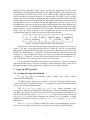
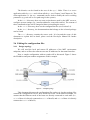
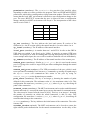
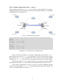
MPT – GRE in UDP based Multipath Communication
Library, User Guide
2015.09.03.
Project leader and main contact: dr. Béla Almási, [email protected],
Faculty of Informatics, University of Debrecen, Debrecen, Hungary.
Developers and members: dr. Márk Kósa, Ferenc Fejes, Róbert Katona, Tamás
Kelemen, Levente Püsök
Table of contents
1
Introduction .................................................................................................... 2
2
Using the MPT project ................................................................................... 3
2.1
Getting the latest distribution ................................................................. 3
2.2
Installing dependencies .......................................................................... 4
2.3
Extracting the tarballs ............................................................................ 4
2.4
Compiling the source code..................................................................... 4
2.5
The directory structure of the MPT environment .................................. 4
2.6
Editing the configuration files ............................................................... 5
2.6.1
Design topology ............................................................................. 5
2.6.2
The interface.conf file ........................................................ 6
2.6.3
Connections.................................................................................... 6
2.6.3.1 General configurations ............................................................... 7
2.6.3.2 Paths ........................................................................................... 9
2.6.3.3 Networks .................................................................................. 11
3
Running the MPT server .............................................................................. 12
4
Sending commands to the server ................................................................. 12
4.1
mpt address ................................................................................... 13
4.2
mpt interface .............................................................................. 13
4.3
mpt reload...................................................................................... 13
4.4
mpt delete...................................................................................... 14
4.5
mpt save .......................................................................................... 14
1
1 Introduction
The current Internet communication environment allows the usage of a single
path only for data transmission in a communication session: the endpoint of a
communication session is identified by the IP address of the host’s interface (and the
port number is also used inside the host for the identification). The single path
assumption is quite acceptable for systems which use a single connection interface or a
“single exit point” to the Internet. On the other hand, a lot of currently used devices
have got factory built-in multiple network interfaces: RJ-45 for the wired network, RF
interface for the Wi-Fi wireless network connection, and mobile phone data transfer
connection interface (e.g., 3G, LTE, or HSPA).
The single-path communication technology is not able to use the advantages of
the multiple available interfaces. The communication performance (e.g., throughput,
reliability) could be highly improved if the networking environment supported the
usage of multiple paths inside a communication session. The term “connection” is used
to refer to the communication session (or probably independent communication
sessions) between two end hosts. The term “path” is used to refer to the pair of the
network cards of the end nodes (identified by the pair of the cards’ IP addresses). Using
a specified path, the packet transmission runs between the given pair of network cards.
To put it simply, the multipath environment means that one connection is able to use
multiple paths (multiple pair of IP addresses) for packet transmission.
The IETF RFC 6824 “TCP Extensions for Multipath Operation with Multiple
Addresses” (MPTCP, published in January of 2013) describes the necessary extensions
for the TCP protocol in order to extend the current TCP implementations for supporting
multiple paths. Actually, the MPTCP works in the transport layer and is restricted to
the TCP protocol.
Figure 1 – The MPT layered architecture
The purpose of the MPT library is to open the possibility for the multipath
environment in the network layer. The architecture of the MPT communication
environment is based on the IETF RFC Draft “GRE in UDP” specification (which is
currently a “work in progress” state specification), but the MPT environment allows
the usage of multiple paths (see Figure 1). In this architecture, we distinguish the
identification of the communication session’s endpoint (application’s socket) and the
physical communication interface. In this mechanism, we create a logical (tunnel)
2
interface on the endpoints, which can be used by the applications for the socket
identification. The IP packets transmitted to the tunnel interface by the application are
encapsulated by the MPT software into a new “GRE in UDP” segment, which will be
sent to the physical network interface for transmission. The MPT server (or MPT
library) offers the possibility to map the packets (coming from the tunnel interface) to
multiple physical interfaces dynamically, so offering the multipath communication for
the application. There is no need to modify the application’s software in this case, as
the application software uses only one single logical interface (the tunnel interface) for
the communication. Also, the application may use the UDP transport protocol over the
tunnel interface, it is not restricted to the TCP protocol. On the other hand, as the MPT
library uses the UDP protocol in the encapsulation process, it will not offer
retransmission and flow control services below the tunnel interface.
Figure 2 – The PDU structure of the MPT-based communication
The structure of the packet transmitted by the MPT environment can be seen in
Figure 2. We have to mention that the fields of “Tunnel IP” and “IP” are absolutely
independent, which means that also the IP versions can be different: it is possible to use
IPv6 for the application (i.e., “Tunnel IP” will be IPv6) and to use IPv4 for the network
interface (i.e., “IP” will be IPv4 in this case). Also, it is possible for the application to
use IPv4 (i.e., “Tunnel IP” will be IPv4) and use IPv6 for the network interface (i.e.,
“IP” will be IPv6). Of course, the two versions can be the same.
To use the MPT multipath communication environment, we have to configure
and start the MPT server (see the next chapters of this document), and we have to use
the tunnel interface for the application’s communication on both endpoints.
2 Using the MPT project
2.1 Getting the latest distribution
To get the MPT
[email protected].
environment,
please
contact
the
e-mail
address
The MPT software library was written in C in Linux. The project is delivered in
various packages as described in Table 1. A package can contain the documentation,
source code, and precompiled binaries.
The mpt-gre-lib32 and mpt-gre-lib64 library packages were
developed for Intel 386 and AMD x86-64 architectures. These distributions contain the
user guide, the header files, the source code of the main program of the MPT server,
and the compiled library files (libmpt.a, cli.a), which can be used to create the
server (mptsrv) and the client (command line interface, mpt) executable. A simple
example configuration is also given in the mpt-gre-lib32 and mpt-gre-lib64
distributions.
The mpt-gre-src package contains the source code including the libraries’
sources, the user guide, the developer’s documentation, and the compiled libraries.
3
File name
Docs
Src
Compiled
library
Executable
mpt-gre-src-YYYY-MM-DD.tar.gz
Yes
Yes
Yes
No
mpt-gre-lib32-YYYY-MM-DD.tar.gz
Yes
No
Yes
Yes
mpt-gre-lib64-YYYY-MM-DD.tar.gz
Yes
No
Yes
Yes
Table 1 – Tarballs
2.2 Installing dependencies
The MPT server needs libc (GNU C Library, including pthread), make, gcc,
iproute, openssl, tar, and gzip packages to be installed. The package names and its
installation method can be different on the various Linux distributions and
architectures. On Debian-based distributions, it can be installed with:
# apt-get install libc6-dev make gcc gcc-multilib libssl-dev iproute
tar gzip
On Intel 386 and AMD x86-64 architectures, the package names may have
different suffixes (e.g., for the Intel 386 architecture this suffix is :i386 , and for AMD
x86-64 architecture this suffix is :amd).
2.3 Extracting the tarballs
The package file contains a complete file structure under a subdirectory called
mpt, which needs to be extracted. We recommend to put this folder into the /opt
directory. To do that, use this command:
$ tar xvzf PACKAGE_FILENAME –C /opt
$ cd /opt/mpt/
2.4 Compiling the source code
On Intel 386 and AMD x86-64 architectures, the mpt and mptsrv can be rebuilt
with the help of the precompiled libraries libmpt.a and cli.a, which can be found
in mpt-gre-lib32 and mpt-gre-lib64 library packages. For this, you can use
the following command:
$ make
You can build both 32-bit and 64-bit version of the programs, depending on the
library package used: you have to use the mpt-gre-lib32 package or the mptgre-lib64 package, respectively. You have to be very careful when using these
libraries because they use the -m32 and -m64 compiler options, which are only valid
on Intel 386 and AMD x86-64 architectures.
If you would like to build the server and the client program for other architectures,
then you have to use the full source package. This package contains a Makefile that
does not use -m32 and -m64 compiler options for building the programs.
2.5 The directory structure of the MPT environment
Everything can be found in the mpt/ folder, every file and folder mentioned later
is relative to that.
4
The binaries can be found in the root of the mpt/ folder. There is a server
application called mptsrv and a client called mpt (see Chapter 3 and Chapter 4). The
client application (i.e. the mpt command) can be used to modify the server working
parameters (e.g. turn off or on a path usage in the system).
In the bin/ directory, there are some scripts that are used by the MPT server to
configure system settings (e.g., interface addresses, route table entries). The content of
these command scripts can be changed without recompiling the source.
In the conf/ directory, there are the configuration files (see Section 2.6).
In the doc/ directory, the documentation that belongs to the selected package
can be found.
The src/ directory contains the source code. It is beyond the scope of this
document to explain this in detail, please read the Developer Manual for further
description.
2.6 Editing the configuration files
2.6.1 Design topology
We will need the local and remote IP addresses of the MPT environment
endpoints, and we will need to allocate two new IP addresses for the tunnel interface.
Now, a sample configuration with two paths will be discussed. Figure 3 shows
the IP address and port number assignments in this example.
Figure 3 – A sample topology
This document discusses the configuration files on host A, but the package files
contain the configuration files for host A and host B too. In the studied example, we
assume that the Ethernet cards of the hosts are directly connected to each other (i.e.,
eth1 of host A is directly connected to eth1 of host B; and eth2 of host A is directly
connected to eth2 of host B).
5
2.6.2 The interface.conf file
The tunnel interface and some general configuration setting can be found in the
conf/interface.conf file. The configuration file is a standard ini file.
Each line has a key and a value part. The name of the key indicates its
functionality. The value is assigned to the key by using the equality (“=”) sign.
Comment lines start with a “;” sign.
[general]
tunnel_num
=
; Accept remote
accept_remote =
cmdport_local =
cmd_timeout
=
1
new connection request
1
60456
25
[tun_0]
name
= tun0
ipv4_addr = 10.0.0.2/24
ipv6_addr = fec0::2/64
Configuration 1 – A sample interface.conf file
The file is made up of sections. The first section contains general information.
Here, we configure how many tunnel and interface we want to handle by using the mpt
software. The current version of mpt handles one tunnel interface, which must be
declared.
In the [general] section the accept_remote key indicates weather the
software enables mptsrv to act like a server. If this parameter is set to 1, then clients
can initiate creating new connections not defined in local configuration files. The server
will accept control commands from remote sites (clients). The cmdport_local
parameter sets the UDP port number which will be used to accept control commands.
The cmd_timeout parameter sets the timeout value (in seconds) of the local client
waiting for the server’s answer (i.e. the mpt command will wait cmd_timeout
seconds for the answer of the server). Usually the server action takes several seconds,
as the server must communicate the action to its peer.
The section [tun_0] describes the tunnel interface parameters. The name key
specifies the name of the tunnel interface, which is used by the operating system to
access to the interface. The ipv4_addr and the ipv6_addr parameters set the IPv4
and IPv6 address (and prefix length) of the tunnel interface. The tunnel interface is
created and configured by the mptsrv application automatically, no further interaction
is required from the user.
2.6.3 Connections
Connection configurations can be found in the conf/connections/
directory and must have .conf extension. An example configuration is shown in
Configuration 2 based on the topology shown in Figure 3.
6
########################## GENERAL INFORMATION ###################
[connection]
name
= MPT_connection_10.0.0.2
permission
= 3
ip_ver
= 4
ip_local
= 10.0.0.2
local_port
= 23456
ip_remote
= 10.0.0.3
remote_port
= 23456
remote_cmd_port
= 60456
path_count
= 2
network_count
= 2
status
= 0
reorder_window
= 0
max_buffdelay_msec = 200
auth_type
= 0
auth_key
= 0
########################## PATHS ############################
[path_0]
interface_name
ip_ver
public_ipaddr
gw_ipaddr
remote_ipaddr
keepalive_time
dead_time
window_size
status
=
=
=
=
=
=
=
=
=
eth1
4
10.1.1.2
10.1.1.2
10.1.1.3
5
11
1
0
[path_1]
interface_name
ip_ver
public_ipaddr
gw_ipaddr
remote_ipaddr
keepalive_time
dead_time
window_size
status
=
=
=
=
=
=
=
=
=
eth2
4
10.2.2.2
10.2.2.2
10.2.2.3
5
11
1
0
####################### NETWORKS #################################
[net_0]
ip_ver
= 4
src_addr
= 11.1.1.0/24
dst_addr
= 21.1.1.0/24
[net_1]
ip_ver
src_addr
dst_addr
= 4
= 12.1.1.0/24
= 22.1.1.0/24
Configuration 2 – A sample connection.conf file
2.6.3.1 General connection configuration – section [connection]
The [connection] section contains the general description of a connection.
Here is the list of the keys of the [connection] section:
name (mandatory): The value is a word (without space) containing the unique name of
the connection. If we use multiple connections, the name must uniquely identify the
connection.
7
permission (mandatory): The permission key may have four possible values
depending on what we want to permit to the program. There are SEND and RECEIVE
permissions, which allow sending and receiving connection updates. The term “SEND”
means that the local MPT environment is allowed to start configuration change to the
peer. The term “RECEIVE” means that the peer is allowed to start a configuration
change, and the local MPT environment will accept it. The interpretation of the values
can be seen in Table 2.
RECEIVE SEND VALUE
-
-
0
-
+
1
+
-
2
+
+
3
Table 2 - Connection update
ip_ver (mandatory): The key indicate the local and remote IP version of the
connection (i.e. the IP version used by the tunnel interface). It can be either 4 or 6.
ip_local (mandatory): The IP address of the tunnel interface.
local_port (mandatory): A number between 1 and 65534. It refers to the GRE in
UDP data port (which is not fixed yet by IANA). It must be an unused UDP port
number. It is going to be used for sending and receiving data packets on any path. If it
is not a unique unused port, the server will be unable to bind and will exit immediately.
ip_remote (mandatory): The IP address of the tunnel interface of the remote peer.
remote_port (mandatory): Similar to local_port, but it is used on the remote
peer. It is going to be used as a target UDP port when sending data through the tunnel
to the peer.
remote_cmd_port (mandatory): The UDP port number of the peer, which is used
to accept control commands. If we start an mpt command (e.g. turning off a path usage)
the mptsrv server will communicate this action to the peer by using its
remote_cmd_port as the destination port number.
path_count (mandatory): The key is an integer p, denoting the number of paths
defined for this connection. The minimum value is 1, the maximum value is 20. This
configuration file must have p sections ([path_n]), where 0 ≤ 𝑛 < 𝑝, describing all
paths of the connection.
network_count (mandatory): The MPT environment can be used to establish tunnel
between networks (i.e. not only the tunnel peers can use the tunnel for communication).
The value must be chosen from the interval [0,20]. This key is an integer l, denoting
the number of networks on which the actual connection is able to route. This
configuration file must have l sections ([net_n]), where 0 ≤ 𝑛 < 𝑙, describing all
networks that belong to the connection.
status (mandatory): The key indicates the initial status of the connection. The value
0 means OK.
reorder_window (optional): The MPT environment can be forced to ensure the
right ordered packet transmission for the tunnel communication. As the delay of the
8
different paths can be different, packet reordering may appear in a packet sequence
transmission. In this case the receiver uses a buffer-array to store the incoming
(unordered) packets. Then the packets are sorted according to the GRE sequence
numbers, so ensuring the ordered transmission to the receiver’s tunnel interface. The
reorder_window value specifies the length (or size) of the buffer-array. The value
of 0 (which is the default value when omitted the key) means, that no sorting will be
performed at the receiver (the packets are transferred to the tunnel interface
immediately when they arrive). The maximum value of the reorder_window
parameter can be 10.000.
max_buffdelay_msec (optional): This key is used only if we require ordered
packet transmission (i.e. reorder_window > 0). If ordered packet transmission is
required max_buffdelay_msec specifies the maximum time (in milliseconds)
while the packet is stored in the buffer-array. If the packet is delayed in the buffer-array
for the specified time it will be transmitted to the tunnel interface, even in the case,
when some packets are missing before the considered packet. The missing packets are
considered as lost packets (i.e. we will not wait more for a lost packet). The arrived
packets are transferred to the tunnel interface according to their GRE sequence number,
so the ordered delivery will be kept also in the case of packet loss.
auth_type (mandatory): The MPT system uses control communication between the
tunnel endpoint. The control communication can be requested to use authentication.
The value 0 means no authentication. Other useable values can be found in Table 3.
auth_key (optional): The auth_key contains the key value of the control
communication authentication. Some algorithms do not need authentication keys. In
this case the specification of the auth_key is not necessary, or will be ignored. The
list of authentication algorithms and their keys required can be found in Table 3.
AUTH. TYPE
AUTH. KEY
Algorithm name
0
No
AUTH_NONE
1
No
AUTH_RAND
2
Yes, 64 byte long in HEX
AUTH_SHA256
Table 3 - Authentication types
2.6.3.2 Path configuration sections – [path_n]
interface_name (mandatory): The value is the name of the physical interface used
by the given path for packet forwarding (e.g. wlan0).
ip_ver (mandatory): Specifies the version of IP used by the path. The value can be 4
or 6.
public_ipaddr (mandatory): Specifies the public IP address of the interface used
for the tunnel communication. If the host is placed into the Global Address Realm, the
public_ipaddr is the IP address of the interface, otherwise (i.e. when the host is
behind a NAT-Box) it is the public address assigned by the NAT-Box to the tunnel
communication session. If the path uses IPv4 and NAT, then the special address value
of “0.0.0.0” can be used to force the mptsrv program to determine the public IP
address automatically.
9
private_ipaddr (optional): The IP address of the physical interface. Can be
omitted, if the public_ipaddr is assigned directly to the interface. When using IPv4
and NAT the special value of “0.0.0.0” can be used to force the mptsrv application to
read and use the first IPv4 address assigned to the interface.
remote_ipaddr (mandatory): Indicates the public IP addresses of the remote
endpoint.
gateway_ipaddr (mandatory): The IP address of the gateway, used to reach the
peer (i.e. remote_ipaddr) using the given path.
keepalive_time (optional): The MPT system monitors the availability of each path
by sending keepalive messages regularly. The key specifies the frequency (ie. the time
between the keepalive messages in seconds) that mptsrv uses for sending keepalives.
The value of zero (which is the default value) means switching off the keepalive
mechanism.
dead_time (optional): If the keepalive mechanism is active, and the host does not
receive keepalive message on the given path from the peer for dead_time seconds
then the path is considered as “dead” and will not be used for data transmission. The
default value is 3*keepalive_time.
weight_out (mandatory): This is the “weight of the path” in the system. The
mptsrv program distributes the outgoing packets between the available paths
according to their weighs. For example, if we have 3 paths with weights 12, 18, 15 then
the “sending cycle” contains 45 packets (the sum of the weights). In each sending cycle
each path will transmit packets according to the weight value. In our example the first
path will transmit 12 packets, the second path will transmit 18, and the third one will
transmit 15 packets in one sending cycle. The sequence of the paths in a sending cycle
is optimized to perform the best approximation to the ratio of the weights at each
timepoint inside a sending cycle.
status (mandatory): This key means the initial state of the path after starting
mptsrv. The value 0 means that the path is usable (working), and the state of the path
is OK.
10
2.6.3.3 Network configuration section – [net_n]
With configured networks in mptsrv, we are able to use the application as a router,
routing the packets among several networks between the tunnel endpoint – establishing
a multipath site-to-site connection.
Figure 4 – A sample topology for networks
####################### NETWORKS #################################
[net_0]
ip_ver
= 4
src_addr
= 11.1.1.0/24
dst_addr
= 21.1.1.0/24
[net_1]
ip_ver
src_addr
dst_addr
= 4
= 12.1.1.0/24
= 22.1.1.0/24
Configuration 3 – The network part of a configuration file.
Every section that belongs to a network configuration start with the “net_”
prefix. In these sections the ip_ver key indicates the version of IP protocol used by
the network. The src_addr describes the source network and its prefix length.
Similarly, the dst_addr key describes the destination network and its prefix length.
With these parameters, we are able to define a route between networks through
the defined connection (i.e. we can establish a multipath connection between sites).
The network configuration can also be used to provide multipath Internet
connection by specifying 0.0.0.0/0 as destination address and prefix length. (The
source is our tunnel address in this case.)
11
3 Running the MPT server
For starting the MPT server, root privileges are necessary. (To obtain root
privileges, the sudo command can be used.) To start the server, just type in:
# ./mptsrv
On successful startup, the output will be something like this:
Tunnel information:
Tunnel interface : tun0
Tunnel device
: /dev/net/tun
Tunnel file desc.: 4
Tunnel ipv4 addr.: 10.0.0.2/24
Tunnel ipv6 addr.: fec0::2/64
CMD server port number : 60456
CMD client port number : 52242
Global server
: 0
If the start was not successful (e.g., root privileges are missing), an error message
will be given, for example:
Tunnel interface IOCTL error. Errno: 77
After the MPT server started, we can check in other terminal windows, whether
the tunnel interface was successfully created.
# ip addr
[...]
5: tun0: <POINTOPOINT,MULTICAST,NOARP,UP,LOWER_UP> mtu 1452 qdisc
pfifo_fast state UNKNOWN qlen 1500
link/none
inet 10.0.0.2/24 scope global tun0
inet6 fec0::2/64 scope site
valid_lft forever preferred_lft forever
After closing the MPT server the IP settings of physical interfaces will not change
back, only the tunnel interface will disappear. If we start the server again, we can calmly
ignore this error message:
RTNETLINK answers: File exists
4 Sending commands to the server
There is a client application called mpt, which can send commands to the server
on the local machine to control its working behavior at runtime. Running the mpt client
without parameters a brief syntax description will be printed (including the available
commands):
$ ./mpt
Usage: mpt [-6] [-port_number] mpt_command mpt_args
-6 : Use IPv6 to communicate with mptsrv
-port_number : The port number of the mptsrv (default: 65010)
[...]
In the following sections the commands of the MPT client will be discussed.
12
4.1 mpt address
This command can be used to add new IP addresses to an interface or remove an
existing one.
A brief description about the usage of this command can be shown by typing mpt
address without arguments:
./mpt address
mpt addr[ess] {add | del} IP_ADDRESS[/PREF_LEN] dev INTERFACE
IP_ADDRESS: The IP address (can be v4 or v6) to manipulate
PREF_LEN:
The prefix length of the manipulated address
Default prefix length: 24 for IPv4, 64 for IPv6.
INTERFACE: The name of the interface related to the manipulated
address
As it can be seen in the description, we can shorten the word address as addr.
There is only two useable operators for this command, add and del (for delete).
The IP address can be given without prefix length or with a prefix length after it,
separated by a “/” sign. It is automatically detected whether the address is IPv4 or IPv6.
If the prefix length is not specified, the default value will be used, which is 24 for IPv4
and 64 for IPv6.
4.2 mpt interface
With this command, we can enable or disable an interface.
A brief description about the usage of this command can be printed by typing
mpt interface without arguments. We can shorten the word interface as int.
Its usage is very simple:
$ ./mpt interface
mpt int[erface] INTEFACE {up | down}
INTEFACE: The name of the interface e.g. eth0
In the example topology, mentioned in Section 2.6.1, you should enable the
physical interfaces after mptsrv is started.
$ ./mpt int eth1 up
$ ./mpt int eth2 up
4.3 mpt reload
This command is used to notify the MPT server that the configuration was
changed and needs to be reloaded. If we do not specify any arguments, the server will
read all connection configuration files from the conf/connections directory
having .conf extension. The server will detect whether the connection is new or
changed in some parameters. We are not able to delete a connection with the mpt
reload command (the mpt delete must be used) for that.
A file name can be specified as an argument in order to reload only that file and
ignore changes in others. (The file name must be given without path.) For example:
13
$ ./mpt reload connection.conf
4.4 mpt delete
To remove a connection, we can use the mpt delete command. It requires an
argument, which is the file name (without path) containing the connection to be
removed. For example:
$ ./mpt delete connection.conf
This command removes all connections described in the connection.conf
file, so we highly recommend to have only one connection in each configuration file.
The configuration file will not be deleted permanently but will be renamed to
*.conf.disabled to prevent them from being loaded next time.
4.5 mpt save
The current configuration can be changed during runtime by remote peers. This
can be enabled as mentioned in Section 2.6.2 with the accept_remote key and in
Section 2.6.3.1 with the permission key.
This command is used to write these connection changes to the configuration
files, so the new settings will remain after server startup or after mpt reload. The
usage of this command can be viewed in mpt help:
mpt save [FILENAME]
FILENAME:
(Optional)
Save changed connection information to config file
The mpt save command can be called without arguments; in this case, all
changes will be written. If the file name is specified (without path), then only changes
related to the connections described in that file will be written.
14
Appendix A – List of figures
Figure 1 – The MPT layered architecture ...................................................................... 2
Figure 2 – The PDU structure of the MPT-based communication ................................ 3
Figure 3 – A sample topology........................................................................................ 5
Appendix B – List of tables
Table 1 – Tarballs .......................................................................................................... 4
Table 2 - Connection update .......................................................................................... 8
Table 3 - Authentication types ....................................................................................... 9
Appendix C – List of configurations
Configuration 1 – A sample interface.conf file .................................................. 6
Configuration 2 – A sample connection.conf file................................................ 7
15