1
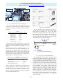
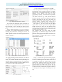
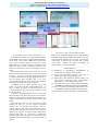
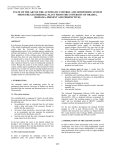
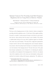
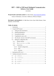
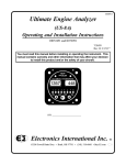
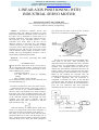
ANNALS OF THE ORADEA UNIVERSITY
Fascicle of Management and Technological Engineering
ISSUE #1, MAY 2014, http://www.imtuoradea.ro/auo.fmte/
LINEAR AXIS POSITIONING WITH
INDUSTRIAL SERVO MOTOR
Xénia Erzsébet TÓTH1, János TÓTH PhD2
email: [email protected]; [email protected]
University of Debrecen Faculty of Engineering
1
goes back from the motor to the controller. It means
that we use a closed-loop system (Fig. 2.).
Abstract— Processions controller devices and
positioning tasks with different conditions are quite
important in industrial automated systems. The aim of
this paper was to materialize a system which is an
industrial application, with using industrial devices.
The main part of his teachable system is a PLC
controlled servo motor. With it the user can set
different positions on the linear axis, with different
velocities; moreover it gives the possibility to define
new places, and to make a program to control a whole
sequential process. The user can control this system
with an industrial display (HMI). Its interface is userfriendly with easy manageability; therefore it can be
used without programming knowledge.
Fig. 1. Structure of a servo motor [3]
Keywords— servo motor, positioning, PLC, HMI,
programming
The user gives the instructions with the HMI, and it
sends them to the PLC. After processing this
information the PLC sends them to the motor controller
which consists of a programmable controller and an
amplifier. The commands about the direction, the
distance, the speed and the acceleration forward to the
actuator (motor). The sensor measures the real values
and sends back the actual information to the controller.
Based on this feedback the controller after the
comparing decides how much correction is necessary.
It continues repeatedly until the instruction is
completed, to maintain the motor at the specified
position and state. The data of the completed motion
goes back to the PLC, and base on this information it
gives the next instruction. The more important
information for the user can be seen on the display.
I. INTRODUCTION
T
HE practical applications of the servo motors is
very important in the industry. In this paper we use
it with a tooth belt linear axis for positioning. It can be
made in different ways, such as
- controlling with a PLC,
- own table which is good for repeatedly
running,
- using a software on the computer.
On the other hand these options can be connected with
an industrial display too.
II. GENERAL INFORMATION ABOUT THE SERVO MOTOR
Positioning means moving a mass from a point to
another. For this we use a FESTO EMMS-AS-55-STM servo motor. The brushless servo motor contains a
three phase stator and a permanent-magnet rotor. The
rotational speed of the rotor depends on the frequency
of the rotational magnetic field through the stator
windings. The rotor moves synchronic with the
magnetic field of the stator, and follows it with the
same revolutions. (Fig. 1.)
With this formula, we can see that the speed of the
motor (n) is proportional with the stator frequency (f)
and in inverse ration to the number of the poles (p).
The name of the used motor means that this three
phased brushless servo motor with the flange size 55
mm is equipped with an inductive multi-turn encoder
mounted on the motor shaft. This feeds information
Fig. 2. The used closed-loop system
139
ANNALS OF THE ORADEA UNIVERSITY
Fascicle of Management and Technological Engineering
ISSUE #1, MAY 2014, http://www.imtuoradea.ro/auo.fmte/
Linear axis
Motor
controller
PLC
HM
I
Fig. 3. The used system
III. USED MOTOR AND ITS CONTROLLER
We use a FESTO EGC-50-600-TB-KF-GK tooth
belt linear axis, with 50 mm axis size, and 600 mm
working stroke. Without it the data of the motor are the
following:
Fig. 4. Driver configuration
For the accuracy of the positioning we use the
encoder which is mounted on the motor shaft, and the
limit switch of the linear axis. We set the home
position with using this Reed sensor. The slider goes to
the limit switch (the side depends on the settings) and
after reaching it, it goes immediately into the opposite
direction. The slider stops when the signal is changing,
this position is taken as the homing point.
TABLE I
GENERAL TECHNICAL DATA OF THE SERVO MOTOR
Nominal torque
Nominal speed
Nominal voltage
Nominal current
Torque at standstill
Maximum speed
Peak torque
Maximum current
0,68 Nm
6600 rpm
360 V
1,2 A
0,98 Nm
7330 rpm
2,7 Nm
5A
With using the linear tooth belt axis, it limits the
range. In this case the maximum speed of the motor is
3000 mm/s, and the maximum acceleration can be 50
mm/s2.
The used motor controller is a FESTO CMMS-AS-C43A-G2 which means the motor technology is AC
synchronous, the nominal current of the motor is 4 A,
and the nominal voltage is 230V AC/50…60 Hz. The
maximal current is 10 A, and the signal speed through
the RS232 port is 9600-115000 bits/s. In Table II the
data of the motor controller can be seen.
Fig. 5. Homing of the linear axis [4]
IV. INTRODUCTION OF THE SYSTEM
The configuration of the motor controller can be
done with the FESTO Configuration Tool program. In
one motor controller with using digital I/O mode we
can store 63 different positions and 8 profiles (velocity,
acceleration and deceleration). To control the system
with the PLC we have to know the pin assignment of
the motor controller, in order to be able to give the
right commands to the enable inputs. During the
process we define the number of the needed positions
with the binary code of the six Record select bits
(Fig.6.). The first one “000000” means the home
position, and after we can choose from 63 positions.
We can define also 8 profiles in the motor controller
and with using these combinations we can make the
PLC program which chooses between them depending
on the user needs.
TABLE II
GENERAL TECHNICAL DATA OF THE MOTOR CONTROLLER
Nominal output current
Peak current
Max. intermediate circuit voltage
Mains frequency
Max. nominal input current
4A
10 A
380 V DC
50 ... 60 Hz
5A
In Fig. 4 the driver configuration can be seen in the
FCT program. Every part of a system should be set
with all parameters by this program, and after it can
calculate the details, for example the maximum speed
which is stored in its memory and it can be found in
the user manual of the devices.
140
ANNALS OF THE ORADEA UNIVERSITY
Fascicle of Management and Technological Engineering
ISSUE #1, MAY 2014, http://www.imtuoradea.ro/auo.fmte/
V. THE CONNECTION BETWEEN PLC AND HMI
The center part of the controlling is a FESTO CPX
Programmable Logic Controller which has a modular
structure and its programming interface is the Festo
Software Tools software. We used an STL
programming language, which describes sequentially
processes.
A Festo FED-500 type HMI (Human-Machine
Interface) provides the necessary information about the
system’s functioning for the user, and makes the
connection between the system and the user. It has a
pressure sensitive (resistive) touch screen and it
communicates with the PC and the PLC via serial port.
The signals of the limit switch and the digital
outputs of the controller go into the two digital inputs
module of the PLC. From the two digital outputs
module of the PLC goes the necessary enable, and
input information towards the motor controller through
a parallel cable which has 25 pins.
The variables that were used during the HMI
programming are defined as flags inside the PLC
program. The structure of the program consists of two
parts: the main program that operates the other lowclass programs, it makes them active or inactive
depends on the criterions.
Fig. 6. Digital I/O of the motor controller
The controller also has digital outputs, with them we
can make sure for example about the errors, the end of
the positioning or the controller is ready for the
operation. In this case we can send the next instruction
to it.
With the Mode Select Bits we can choose between
two modes: “00” is simple positioning and “10” means
teaching new positions or crawling on the axis. In
Single Position Set Mode we use the selection bits to
define positions. We can see the used positions and
profiles in the Fig. 7.
Fig. 7. Used positions, velocities in the FCT
Fig. 9. Part of the main program of the PLC
In Jogging/Teaching Mode with DIN10 and DIN11
inputs we can change the direction and rotate the motor
slowly with 50 mm /s and after 1s the speed changes to
200 mm/s (Fig.8.). With this function we can find new
positions, and with sending an impulse to DIN8 we can
store them to the DIN1-DIN4 defined place.
In Fig. 9. can be seen a part of the main program,
when it is deciding about the mode, in step Mode_sel
the states is checking all the time. With the first “if” it
is looking for whether the Home button has been
pushed or not. With the second “if” it does the same
with the reset button. If these variables are true the
program jumps into another steps. We are also pay
attention of the Mode select bits statements, and base
on them it activates or deactivates programs. If there is
not homing the main program is continually be in this
step.
Fig. 8. Jog parameters
141
ANNALS OF THE ORADEA UNIVERSITY
Fascicle of Management and Technological Engineering
ISSUE #1, MAY 2014, http://www.imtuoradea.ro/auo.fmte/
Fig. 10. The menu structure [6]
VII. CONCLUSION AND RECOMMENDATIONS
VI. INTRODUCTION OF THE USER INTERFACE
This process and these settings can be quite difficult,
and needs the good knowledge of the devices. Our aim
was to create an interface to this system, with a simple
structure for a common user. It means that it can be
used easily without the deep knowledge of
programming, or of using softwares.
For the easier operating we created a menu structure
which can be seen in Fig. 10. With pushing the buttons
on the main screen (in the middle) we can select the
other screens. Before starting the program it goes
automatically to its home position, but with the home
button the user can do it manually whenever it is
necessary. The program can be restarted with the reset
button.
In the Positioning screen (right on the top) we can
select between 8 fixed positions, which can be seen in
the Fig. 7. The long green line under this function
symbolizes the linear axis, and the target position on it.
We can choose fixed velocities (Fig. 7.) to every
position and the indicator lights on the right side show
information about the state of the controller.
In Manual move & Teach position screen (left
below) we can move the dray with pushing move – or
move + buttons. If it stops we can select a place (1-7)
in the controller for the new position, and save it with
the Teach button.
If we have manually taught positions we can load
them with the screen on the left top. We can choose the
number of the position and push the move button. It
will go to the defined place with a fixed velocity (200
mm/s).
With the last screen on the right below, called
Position set table, we can set a whole sequential
program. We can describe the positions, choose a
velocity and set a delay time, which means the time for
waiting before starting the movement. After giving the
details every used line should be fixed, otherwise the
program skips them. If a position is reached the
indicator light of the row shows it. The process starts
repeatedly from the beginning if the repeat button is
pushed.
VIII. REFERENCES
[1] Mohamed A. El-Sharkawi: Fundamentals of
electric drives, Cengage Learning, 2000
[2] János Tóth: Electrical Actuators, University of
Debrecen Faculty of Engineering, 2012
[3] David Hoey, Dan Sandoval, Edward Gasper: TP
800 e-drives - Reference notes, Festo Didactic
GmbH & Co., D-73770 Denkendorf, 2002
[4] http://www.festo.com/net/SupportPortal/Files/102
73/EMMS-AS_ENUS.pdf download: 20.04.2014.
[5] http://www.festo.com/net/SupportPortal/Files/102
72/CMMS-AS_ENUS.pdf download: 20.04.2014.
[6] http://www.youtube.com/watch?v=c2RhXUsSxtE
142