1
Drive Technology \ Drive Automation \ System Integration \ Services
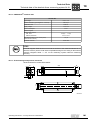
SL2 Synchronous Linear Motors
Edition 11/2008
16630815 / EN
Operating Instructions
SEW-EURODRIVE – Driving the world
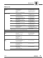
Contents
1
General Information .......................................................................................... 5
1.1 How to use the operating instructions....................................................... 5
1.2 Structure of the safety notes ..................................................................... 5
1.3 Rights to claim under warranty ................................................................. 6
1.4 Exclusion of liability................................................................................... 6
1.5 Copyright notice ........................................................................................ 6
2
Safety Notes ...................................................................................................... 7
2.1 Preliminary information ............................................................................. 7
2.2 General information .................................................................................. 8
2.3 Target group ............................................................................................. 9
2.4 Designated use ......................................................................................... 9
2.5 Integral part of the product...................................................................... 10
2.6 Behavior and immediate measures in case of accidents........................ 10
2.7 Waste disposal........................................................................................ 10
3
Product Description and Overview of Types................................................ 11
3.1 System environment ............................................................................... 11
3.2 Documentation........................................................................................ 12
3.3 SL2 product designs ............................................................................... 13
3.4 System components for SL2-Advance System and SL2-Power System 14
3.5 Type code ............................................................................................... 16
3.6 Nameplate............................................................................................... 20
3.7 Scope of delivery for system components .............................................. 22
4
Transportation and Storage ........................................................................... 23
4.1 Notes....................................................................................................... 23
4.2 Transport................................................................................................. 23
4.3 Packaging ............................................................................................... 26
4.4 Corrosion protection and storage conditions .......................................... 29
4.5 Coating.................................................................................................... 29
4.6 Return delivery to SEW-EURODRIVE .................................................... 29
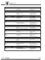
5
Mechanical Installation................................................................................... 30
5.1 Notes....................................................................................................... 30
5.2 Installation tolerances ............................................................................. 31
5.3 Required tools......................................................................................... 32
5.4 Installing SL2-Basic ................................................................................ 33
5.5 Installing the SL2-Advance System and SL2-Power System ................. 34
5.6 Installing the SL2 secondaries ................................................................ 36
5.7 Installing the AL1H measuring system.................................................... 38
5.8 Mechanical load capacity SL2-Advance and SL2-Power ....................... 39
5.9 Installing customer components on primary ........................................... 40
6
Electrical Installation ...................................................................................... 42
6.1 Electrical connection .............................................................................. 43
6.2 Prefabricated cables for SL2-Advance System / SL2 -Power System.... 47
7
Startup.............................................................................................................. 63
7.1 Prerequisites for startup.......................................................................... 64
7.2 Commutation travel process ................................................................... 64
7.3 MOVIDRIVE®: Startup procedure ........................................................... 66
7.4 MOVIDRIVE®: Calculating travel parameters ......................................... 70
7.5 MOVIAXIS®: Startup procedure.............................................................. 72
8
Malfunctions .................................................................................................... 77
8.1 MOVIDRIVE®: Faults during commutation search ................................. 78
8.2 MOVIDRIVE®: Problems during operation ............................................. 79
8.3 MOVIAXIS®: Problems during commutation search ............................... 80
8.4 MOVIAXIS®: Problems during operation ................................................ 81
Operating Instructions – SL2 Synchronous Linear Motors
3
Contents
4
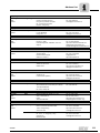
9
Inspection / Maintenance ............................................................................... 82
9.1 Notes....................................................................................................... 82
9.2 General maintenance work ..................................................................... 83
9.3 Additional maintenance for Power version.............................................. 83
10
Technical Data................................................................................................. 84
10.1 SL2-Basic motor data ............................................................................. 84
10.2 SL2-Advance System motor data ........................................................... 86
10.3 SL2-Power System motor data ............................................................... 88
10.4 Derating ................................................................................................. 90
10.5 Maximum force with MOVIDRIVE® MDX61B ......................................... 91
10.6 Maximum forces with MOVIAXIS® .......................................................... 94
10.7 Unit designation for MOVIDRIVE® MDX61B .......................................... 97
10.8 Unit designation for MOVIAXIS® basic units .......................................... 98
10.9 Technical data of the absolute linear measuring system AL1H ............ 100
10.10 Technical data for linear guide systems................................................ 103
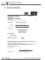
11
Declaration of Conformity ............................................................................ 106
11.1 SL2 synchronous linear motors ............................................................ 106
12
Index............................................................................................................... 116
Operating Instructions – SL2 Synchronous Linear Motors
General Information
How to use the operating instructions
1
General Information
1.1
How to use the operating instructions
1
Betriebsanleitung
The operating instructions are an integral part of the product and contain important
information for operation and service. The operating instructions are written for all
employees who assemble, install, startup, and service this product.
The operating instructions must be kept available in a legible condition. Ensure that
persons responsible for the system and its operation, as well as persons who work
independently on the unit, have read through the operating instructions completely and
understood them. If you are unclear about any of the information in this documentation,
or if you require further information, please contact SEW-EURODRIVE.
1.2
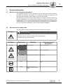
Structure of the safety notes
The safety notes in these operating instructions are designed as follows:
Pictogram
SIGNAL WORD!
Type and source of danger.
Possible consequence(s) if the safety notes are disregarded.
•
Pictogram
Example:
Measure(s) to prevent the hazard.
Signal word
Meaning
Consequences if
disregarded
DANGER
Imminent danger
Severe or fatal injuries
WARNING
Possible dangerous situation
Severe or fatal injuries
CAUTION
Possible dangerous situation
Minor injuries
STOP
Possible damage to property
Damage to the drive system or its environment
NOTE
Useful information or tip
Simplifies handling of the drive
system.
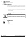
General hazard
Specific hazard,
e.g. electric shock
Operating Instructions – SL2 Synchronous Linear Motors
5
General Information
Rights to claim under warranty
1
1.3
Rights to claim under warranty
Adhering to the operating instructions is a prerequisite for fault-free operation and the
fulfillment of any right to claim under warranty. Therefore, read the operating instructions
before you start working with the unit!
Make sure that the operating instructions are available to persons responsible for the
plant and its operation, as well as to person who work independently on the unit. You
must also ensure that the documentation is legible.
1.4
Exclusion of liability
You must comply with the information contained in these operating instructions to
ensure safe operation of the SL2 linear motor and to achieve the specified product
characteristics and performance features. SEW-EURODRIVE assumes no liability for
injury to persons or damage to equipment or property resulting from non-observance of
the operating instructions. In such cases, any liability for defects is excluded.
1.5
Copyright notice
© <2008> - SEW-EURODRIVE. All rights reserved.
Copyright law prohibits the duplication, modification, distribution, and use of any part of
this document for ulterior purposes.
6
Operating Instructions – SL2 Synchronous Linear Motors
Safety Notes
Preliminary information
2
Safety Notes
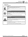
2.1
Preliminary information
2
NOTE
Due to the strong permanent magnets installed in the secondaries of the SL2 linear
motors, the following safety regulations must be observed.
Also observe the supplementary safety notes in the individual sections of this
manual.
DANGER
The strong magnetic fields and the associated high ferromagnetic attraction
forces can be directly harmful to your health, for example for persons with
cardiac pacemakers, or indirectly as a result of fast motor movements and high
thrust forces.
Severe or fatal injuries.
•
Work must not be carried out by persons with cardiac pacemakers.
DANGER
Danger caused by magnetic field
Even at a distance of 100 mm, the magnetic flux density of the secondaries present is
< 5 mT (at 150 mm < 0.5 mT). Since the magnetic flux density in SL2 linear motors is
generated exclusively by the magnetic fields of the secondaries, this value is independent from the operating status of the SL2 linear motor.
Severe or fatal injuries.
•
Special caution needs to be the rule in close proximity (distances < 50 mm) to the
secondaries due to the high attraction forces. Magnetic forces are often underestimated since they are not visible.
•
Magnetic attraction forces often arise abruptly in the immediate proximity range and
can grow in excess of several 100 kg for medium-sized objects.
Operating Instructions – SL2 Synchronous Linear Motors
7
Safety Notes
General information
2
2.2
General information
DANGER
During operation, the linear motor can have movable parts.
Severe or fatal injuries.
•
All work related to transportation, putting into storage, setup/mounting, connection,
startup, maintenance and repair may only be carried out by qualified personnel
observing
– The relevant detailed operating instructions
– The warning and safety signs on the motor
– All other project planning documents, operating instructions and wiring diagrams
related to the drive
– The specific regulations and requirements for the system
– The national/regional regulations governing safety and the prevention of
accidents
•
Never install damaged products
•
Removing covers without authorization, improper use as well as incorrect installation or operation may result in severe injuries to persons or damage to property.
•
Do not lead any metallic objects that are heavy (> 1 kg) or have a wide surface
(> 1 dm²) to the secondary with unprotected hands to the secondary.
•
Place at least two pointed wedges made of firm, non-magnetic material, such as
brass or stainless steel (edge angle approx. 10° - 15°) and a hammer ready to free
parts of the body that have been trapped. If necessary, e.g. if mounting space is
limited, customized installation appliances should be used to facilitate and safeguard work.
•
Do not bring watches and magnetizable data carriers (such as credit cards, disks,
etc.) into close proximity <100 mm of SL2 linear motors.
Refer to the documentation for additional information.
WARNING
Touching the linear motors when they have not cooled down could result in burns.
Linear motors can have a surface temperature of over 100 °C.
Danger of burns
•
8
Never touch the linear motor during operation or in the cool down phase once it has
been switched off.
Operating Instructions – SL2 Synchronous Linear Motors
Safety Notes
Target group
2.3
2
Target group
SL2 linear motors represent a potential hazard for persons and property. Consequently,
assembly, installation, startup and service work may only be performed by trained
personnel who are aware of the potential hazards.
Staff must be appropriately qualified for the task in hand and be familiar with the assembly, installation, startup and operation of the product. They must read the operating
instructions, in particular the safety notes section, carefully and ensure that they understand and comply with them.
2.4
Designated use
SL2 synchronous linear motors are motors for industrial and commercial systems. If
motors are subject to loads other than those permitted, or if they are used areas of
application other than industrial and commercial systems, you must first consult with
SEW-EURODRIVE.
Do not operate the unit until you have ensured that the machine complies with the Low
Voltage Directive 73/23/EEC and that the conformity of the end product has been determined to comply with the Machinery Directive 98/37/EC.
Technical data and information about permissible conditions can be found on the nameplate and in the documentation.
Operating environment
The following uses are prohibited unless the units are expressly designed for the
purpose:
•
Use in potentially explosive areas.
•
Use in areas exposed to harmful oils, acids, gases, vapors, dust, radiation. Please
contact SEW-EURODRIVE if you have any questions on the environmental conditions.
•
Use in non-stationary applications that are subject to mechanical vibration and
impact loads in excess of the requirement of EN 50178.
Safety functions
SL2 linear motors are not allowed to perform any safety functions unless they are
subordinate to other safety systems.
Use higher-level safety systems to ensure protection of equipment and personnel.
Operating Instructions – SL2 Synchronous Linear Motors
9
Safety Notes
Integral part of the product
2
2.5
Integral part of the product
The operating instructions are an integral part of the SL2 linear motors and contain
important information for operation and service. The operating instructions are written
for all assembly, installation, startup and service staff who are involved in the installation
and maintenance of SL2 synchronous linear motors.
2.6
Behavior and immediate measures in case of accidents
•
If the machine is connected to the power supply system, press the EMERGENCY
OFF button immediately.
•
Request first aid immediately.
•
You need the tools mentioned previously to free body parts jammed in between two
secondaries or a secondary and a ferromagnetic component (e.g. steel plate, steel
carrier, machine bed, tool). Separate the components at the separation gap using the
pointed wedge.
WARNING
Danger caused by magnetic field
Severe or fatal injuries.
•
2.7
The magnetic forces are always present regardless of the operating status of the
system.
Waste disposal
This product consists of:
•
Iron
•
Aluminum
•
Copper
•
Plastics
•
Electronic components
Dispose of all components in accordance with applicable regulations.
10
Operating Instructions – SL2 Synchronous Linear Motors
Product Description and Overview of Types
System environment
3
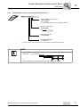
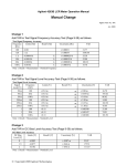
Product Description and Overview of Types
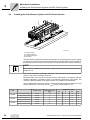
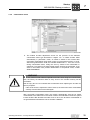
3.1
System environment
MOVITOOLS
®
3
Startup synchronous linear motors
Documentation
SL2 catalog
MOVIDRIVE®
frequency inverter
MOVIAXIS ®
multi-axis servo inverter
Drive Engineering
Practical Implementation
SL2 operating instructions
SL2 Synchronous Linear Motors
SL2-Basic
Power cable
Feedback cable
SL2-Advance System
SL2-Power System
Length measuring system
AL1H
63372AEN
Operating Instructions – SL2 Synchronous Linear Motors
11
Product Description and Overview of Types
Documentation
3
3.2
Documentation
Internet
You will find the current documentation on SL2 synchronous linear motors in many
languages on the SEW-EURODRIVE homepage (http://www.sew-eurodrive.com).
Here, you can download the files directly or order a printed copy from SEWEURODRIVE.
Manuals
CAD data
Documentation
12
•
MOVIDRIVE® B
•
MOVIAXIS® project planning manual
CAD data is available from SEW-EURODRIVE for all sizes on request.
•
2D-DXF, DWG and TIF
•
3D-IGES, STEP
•
"SL2 Synchronous Linear Motors" catalog
Operating Instructions – SL2 Synchronous Linear Motors
Product Description and Overview of Types
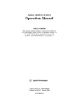
SL2 product designs
3.3
3
SL2 product designs
SEW-EURODRIVE offers three product designs for SL2 linear motors:
3.3.1
SL2-Basic
Motor package and secondaries
SL2-Advance
System
Motor package integrated in cooling unit and secondaries. Prepared
for installation of linear guides and the linear encoder.
SL2-Power
System
Motor package integrated in motor cooling unit with forced cooling
fan and secondaries. Prepared for installation of linear guides and
the linear encoder.
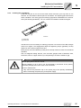
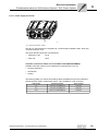
SL2-Basic
[1]
[2]
[3]
52619AXX
[1] Primary
[2] Electrical connection in form of a cable extension
[3] Secondaries with permanent magnets
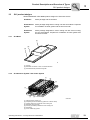
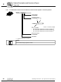
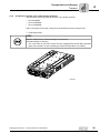
3.3.2
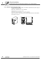
SL2-Advance System / SL2-Power System
[1]
[2]
[5]
[3]
[7]
[4]
[6]
55394AXX
[1]
[2]
[3]
[4]
[5]
[6]
[7]
Optional motor cooling unit
Prepared grooves as retaining system for customer setup
Forced cooling fan of optional motor cooling unit
Electrical plug connector
Primary (not visible) installed in motor cooling unit
Secondary
Linear measuring system
Operating Instructions – SL2 Synchronous Linear Motors
13
Product Description and Overview of Types
System components for SL2-Advance System and SL2-Power System
3
3.4
System components for SL2-Advance System and SL2-Power System
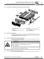
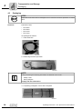
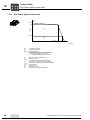
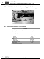
3.4.1
System description
The linear motor is installed into a motor cooling unit at the factory for product groups
SL2-Advance System and SL2-Power System.
55388AXX
For motor sizes
•
SL2-P050,
•
SL2-P100,
•
SL2-P150,
the motor cooling unit is available for all lengths (except for SL2-P150VS) as system
components.
14
Operating Instructions – SL2 Synchronous Linear Motors
Product Description and Overview of Types
System components for SL2-Advance System and SL2-Power System
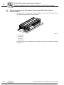
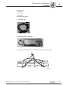
3.4.2
3
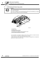
Part drawing of the SL2-Advance System and SL2-Power System
[7]
[5]
[4]
[1]
[2]
[3]
[8]
[6]
55392AXX
[1]
[2]
[3]
[4]
Motor cooling unit
Forced cooling fan (in SL2-Power System only)
Primary
Integrated floating bearing for temperature
compensation
[5] End plate
[6] Front panel with power plug and fan guard
[7] Slots for installation of components by customer
(T-slot nuts supplied)
[8] Linear measuring system
3.4.3
Design of the subsystems
The motor is installed into the motor cooling unit by SEW-EURODRIVE and connected
to a standardized power plug. The 24 V power supply for the fans is provided by a
separate plug when using forced cooling fans.
3.4.4
Fields of application for the SL2-Advance System
The SL2-Advance System can basically be used in all fields of application for the SL2
linear motor. There are no limitations.
WARNING
When using in hoists
The motor system is not equipped with its own holding brake. With incremental
encoder, commutation search is required after each reset.
Severe or fatal injuries.
•
3.4.5
SEW-EURODRIVE strongly recommends that you use an absolute measuring
system when using the system as hoist drive. You find information in section 5 of
the "SL2 Synchronous Linear Motors" catalog.
Fields of application for the SL2-Power System
The use of the motor cooling unit with forced cooling fans is limited to enclosure IP54.
Operating Instructions – SL2 Synchronous Linear Motors
15
Product Description and Overview of Types
Type code
3
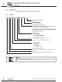
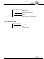
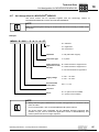
3.5
Type code
The following diagram shows the type code structure.
3.5.1
Primary
SL2 - P 050 VS - 030 - T - B - KVX1 - 490 - 00
Standard / Special design
Winding voltage
DC link voltage 490 V
Cable extension (SL2-Basic)
For more information on the position and length, see the
following page (combination overview 1)
or plug connector (SL2-Power System and SL2-Advance
System) position, special design, see the following page
(combination overview 2)
Motor design
B = SL2-Basic
A = SL2-Advance System
P = SL2-Power System
T = Temperature sensor TF / K = KTY
Vrated: 010 = 1 m/s; 030 = 3 m/s; 060 = 6 m/s
Length of primary
VS = very short
S = short
M = medium
ML = medium long
Active width of the primary
25 mm, 50 mm, 100 mm, 150 mm, 200 mm or 250 mm.
Primary
Second generation of synchronous linear motor
NOTE
The standard design appears in bold.
16
Operating Instructions – SL2 Synchronous Linear Motors
Product Description and Overview of Types
Type code
3.5.2
3
1. Combination overview for SL2-Basic/cable extension
SL2-P...-...-K V X 1-...
Length of cable extension in [m]
1 m = standard
4 m = optional
0 = 0.5 m cable length only for connection version1)
Position of cable outlet
X = standard
X
Electrical connection
V = connected
K = Cable extension
A = Connector
1) Connector version AVX= refers to a 0.5 m cable extension with prefabricated connector
NOTE
•
The SL2-Basic version with Irated ≤ 26 A is available with Intercontec round
connector → → type AVX0 .
0,5 m
•
SL2 primaries with a cable length of 2 m are no longer available.
Operating Instructions – SL2 Synchronous Linear Motors
17
Product Description and Overview of Types
Type code
3
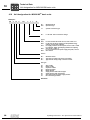
3.5.3
2. Combination overview for SL2-Advance and SL2-Power System / connector position
SL2-P...-...-S S X S-...
Special design
S = Standard
Connector position
X = Standard (Y, Z, W)
Z
Y
X
W
The following combinations of motor + connector position
are not available:
• SL2-050 Power System with connector position Z1)
• SL2-100 Power System with connector position W1)
• SL2-150 Power System with connector position Z1)
Mechanical design
S = Standard
Connector
1) Collision with M12 24 V connector
NOTE
The standard design appears in bold.
18
Operating Instructions – SL2 Synchronous Linear Motors
Product Description and Overview of Types
Type code
3.5.4
3
Secondary
SL2 - S 050 - 128
Length of secondary
64 mm, 128 mm, 256 mm and 512 mm
Active magnet width of the secondary
25 mm, 50 mm, 100 mm, 150 mm, 200 mm and 250 mm
Secondary
Second generation of synchronous linear motor
3.5.5
Linear measuring system
AL1H
HIPERFACE® interface
Version
Linear measuring system
Absolute encoder
Operating Instructions – SL2 Synchronous Linear Motors
19
Product Description and Overview of Types
Nameplate
3
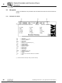
3.6
Nameplate
Labels are attached to the primaries and secondaries that show the technical data as
follows:
3.6.1
Nameplate SL2-Basic
[1]
[2]
[3]
[4]
SL2 – P050VS – 030 – T – B – KVX1 – 490 –00
561433
AB 01.30758540.03.0001.04
FPEAK [N]
F1 [N]
Fnenn [N]
ke [vs/m]
RU-V [Ω]
:
:
:
:
:
IPEAK [A]
I1 [A]
Inenn [A]
kf [N/A]
LU-V [mH]
:
:
:
:
:
Sach-Nr. 13326414
Iso.Kl.
IP65
U [VDC ] :
v nenn [m/s] :
m [kg]
:
Bruchsal / Germany
53352AXX
[1]
[2]
[3]
[4]
FPeaK
F1
Fnenn
ke
RU-V
IPEAK
l1
Inenn
kf
LU-V
Iso.KL.
IP
U
vnenn
m
=
=
=
=
=
=
=
=
=
=
=
=
=
=
=
=
=
=
=
Type code
Customer order number
Production number
Part number
Peak force
Maximum force available up to v1
Permanent force
Voltage constant
Winding resistance1)
Maximum current
Current at F1
Rated current
Force factor
Inductance1)
Insulating material class
Degree of protection
Voltage
Velocity up to which the rated force is available
Mass
1) Half the conductor value (UV value) is used for startup.
20
Operating Instructions – SL2 Synchronous Linear Motors
Product Description and Overview of Types
Nameplate
3.6.2
3
Nameplate SL2-Advance System SL2-Power System
76646 Bruchsal/Germany
Type SL2-P050S-30-T-P-SSXS-490-00
No. 01.1234567801.0001.06
F peak 1300 N
I peak 11,8 A
kg
1000 N
8,7 A
F1
I1
IP
760 N
6,1 A
FN
IN
76 vs/m
131 N/A
ke
kf
7,0
R U-V
L U-V 45,0 mH
490 V DC
B
U
Ins.Cl.
3,4 m/s
vN
Part-No.
12,3
54
Made in Germany
1332 783 6
59476AXX
Type
No.
FPeaK
F1
FN
ke
RU-V
U
vN
IPEAK
l1
IN
kf
LU-V
Ins.Cl.
Part no.
kg
IP
=
=
=
=
=
=
=
=
=
=
=
=
=
=
=
=
=
=
Type code
Customer order number
Peak force
Maximum force available up to v1
Permanent force
Voltage constant
Winding resistance1)
Voltage
Velocity up to which the rated force is available
Maximum current
Current at F1
Rated current
Force factor
Inductance1)
Insulating material class
Part number
Weight
Degree of protection
1) Half the conductor value (UV value) is used for startup.
3.6.3
Nameplate for secondaries
[1]
[2]
[3]
SL2 – S050 – 128
AB 01.30758450.03.0002.04
[5]
Sach-Nr. 13327046
Bruchsal / Germany
561433
[4]
53353AXX
[1]
[2]
[3]
[4]
[5]
= Type code
= Customer order number
= Date of production
= Production number
= Part number
Operating Instructions – SL2 Synchronous Linear Motors
21
Product Description and Overview of Types
Scope of delivery for system components
3
3.7
Scope of delivery for system components
The scope of delivery for SL2 linear motors comprises:
•
Primaries
•
Secondaries with permanent magnets
•
SL2-Advance System
– Primary installed in motor cooling unit
– Electrical plug connector
– T-slot nuts for mounting of customer loads are included
•
SL2-Power System
– Primary installed in motor cooling unit
– Electrical plug connector
– Forced cooling fan completely assembled and electrically wired to M12 plug
connector
– T-slot nuts for mounting of customer loads are included
Not included in
the scope of
delivery:
22
•
Prefabricated power and feedback cables
•
Control and regulation systems such as MOVIDRIVE®
•
Linear measuring system
•
Encoder mount-on components
•
Linear guide systems
•
Linear measurement systems (except for AL1H)
•
Cable carriers
•
Brake systems
•
Buffers / shock absorbers
Operating Instructions – SL2 Synchronous Linear Motors
Transportation and Storage
Notes
4
Transportation and Storage
4.1
Notes
4
STOP
Improper transport may result in damages to the linear motor.
Potential damage to property!
•
Strictly observe the notes in this chapter.
•
Use suitable, sufficiently rated handling equipment if necessary.
•
Inspect the shipment immediately upon receipt for any damage that may have
occurred during transportation. Inform the shipping company immediately in the
event of damage. It may be necessary to preclude startup.
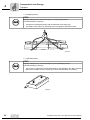
Use suitable means of transport with adequate space if necessary. Remove securing
devices used for transportation prior to startup.
•
Mark the storage locations of secondaries ("Danger! Strong magnetic fields",
pictograms).
•
Never store secondaries unpacked; use non-magnetic packaging material with a
thickness of at least 2 cm on the magnetic side.
•
Observe the warning instructions on the packaging.
•
Keep storage area dry.
•
Protect storage sites from heat.
•
For transportation of machines or components with primaries or secondaries already
installed on travel axis/axes: Lock the axis/axes to prevent accidental movement
(due to missing self-locking mechanism).
4.2
Transport
4.2.1
SL2-Basic primaries
Primaries of the SL2-Basic
•
SL2-P100M/ML
•
SL2-P150S/M/ML
•
SL2-P200S/M/ML
•
SL2-P250VS/S/M/ML
with a net weight of more than 18 kg are equipped with the following transportation aids:
Operating Instructions – SL2 Synchronous Linear Motors
23
4
Transportation and Storage
Transport
1. Packaged primary
STOP
Improper transport may result in damages to the packaged primary
Potential damage to property!
•
Transport the packaged primary with the attached crane slings only.
•
The weight of the primary is indicated on the nameplate or dimension sheet.
53465AXX
2. Unpacked primary
STOP
Improper transport may result in damages to the unpackaged primary.
Potential damage to property!
•
The primary is equipped with two M6 threads for transportation with lifting eyebolts
(parts not included in scope of delivery) for further transportation or handling.
53366AXX
24
Operating Instructions – SL2 Synchronous Linear Motors
Transportation and Storage
Transport
4.2.2
4
SL2-Advance System / SL2 -Power System primaries
The primaries of the SL2-Advance Systems / SL2-Power Systems
•
SL2-P050M/ML
•
SL2-P100S/M/ML
•
SL2-P150S/M/ML
with a net weight of more than 18 kg can be removed from the box using a hoist.
1. Unpacked primary
STOP
Improper transport may result in damages to the primary.
Potential damage to property!
•
The T-slot nuts on the motor cooling unit are equipped with two M8 lifting eyebolts
(parts not included in scope of delivery) for further transportation or handling.
55488AXX
Operating Instructions – SL2 Synchronous Linear Motors
25
Transportation and Storage
Packaging
4
4.3
Packaging
STOP
Protective cover must not be damaged since it ensures corrosion protection of metal
parts.
Primaries
Primaries of size:
•
SL2-P025
•
SL2-P050
•
SL2-P100
•
SL2-P150
are packaged as follows:
1. Cable extension
53321AXX
2. Plastic bag/corrosion protection
53322AXX
NOTE
A bag containing the following information is attached to the motor:
•
Safety notes
•
Wiring diagram
Comply with this information.
3. Completely packaged in carton with nameplate
53323AXX
26
Operating Instructions – SL2 Synchronous Linear Motors
Transportation and Storage
Packaging
4
Primaries of size:
•
SL2-P150
•
SL2-P200
•
SL2-P250
are packaged as follows:
1. Cable extension
53321AXX
2. Plastic bag/corrosion protection
53322AXX
3. Completely packaged in carton with plywood support or transport slings
53465AXX
Operating Instructions – SL2 Synchronous Linear Motors
27
4
Transportation and Storage
Packaging
Secondary for all
motor types
STOP
Protective cover must not be damaged since it ensures corrosion protection of metal
parts.
1. Box with packaging straps
53325AXX
2. Contents secondary box:
•
•
•
28
Secondary packed in protective cover
Safety notes and warning labels enclosed loose inside box
Touch guard magnetic surface (wooden board)
Operating Instructions – SL2 Synchronous Linear Motors
Transportation and Storage
Corrosion protection and storage conditions
4.4
4
Corrosion protection and storage conditions
The motor parts are protected against corrosion for five years in closed original
packaging.
Observe the following storage conditions for SL2 linear motors:
•
Store the SL2 linear motors inside.
•
Keep storage area clean and dry.
•
Maintain a storage temperature between –5 °C and +70 °C
•
Relative humidity not to exceed 95 %
•
Original packaging must be free from damages
Stored SL2 linear motors must be equipped with the following warning labels:
Warning
4.5
Magnetic
Coating
SL2-Basic
The motor parts are coated black matte (EPOXY two-component single coat paint) as
standard.
SL2-Advance System / SL2 -Power System
With the exception of the front area, all motor parts are anodized with a black coating.
The front side of the motor is coated with black matte.
4.6
Return delivery to SEW-EURODRIVE
Return primary and secondary components in original packaging only.
WARNING
Danger caused by magnetic field
Severe or fatal injuries.
•
Cover the magnetic side of the secondaries with a wooden board (thickness 2 cm)
over the entire surface and connect. Special caution needs to be the rule in close
proximity (distances < 50 mm) to the secondaries due to the high attraction forces.
Magnetic forces are often underestimated since they are not visible.
•
Magnetic attraction forces often arise abruptly in the immediate proximity range.
Operating Instructions – SL2 Synchronous Linear Motors
29
Mechanical Installation
Notes
5
5
Mechanical Installation
5.1
Notes
DANGER
Danger caused by magnetic field
Severe or fatal injuries.
•
Never place secondaries on metal.
•
Never place a primary directly on a secondary.
•
Hold the tools firmly (with both hands). Slowly guide the tools to the secondary.
•
Wear work gloves during installation.
•
Do not remove the packaging of the secondary until directly before it is installed.
•
Carry out installation work in pairs only.
•
Cover already installed secondaries with at least 2 cm of non-magnetic material
(e.g. wood) during installation.
•
Use customized installation appliances to facilitate and safeguard work, if necessary (e.g. if mounting space is limited).
•
Make sure that the primary is grounded according to regulations with the PE
grounding bar in the control cabinet as a reference potential.
•
Attach the enclosed warning sign in a prominent position or in the vicinity of the
secondaries installed.
DANGER
Risk of injury due to electric shock.
Severe or fatal injuries.
•
30
Make sure that the primary is grounded according to regulations with the PE
grounding bar in the control cabinet as a reference potential.
Operating Instructions – SL2 Synchronous Linear Motors
Mechanical Installation
Installation tolerances
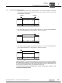
5.2
5
Installation tolerances
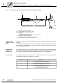
[1]
[2]
+/-0.1
+/-0.1
[3]
L2
L1
+/-0.2
+/-0.2
53649AXX
[1] Installation of primary
with reference to the largest primary, max. deflection length / width 0.1 mm
[2] Secondary
with reference to 512 mm length, max. deflection 0.1 mm
[3] Installation of secondary
[L1] ± 0.3 mm with reference to total length
[L2] ± 0.2 mm with reference to total length
Operating Instructions – SL2 Synchronous Linear Motors
31
Mechanical Installation
Required tools
5
NOTE
For information on the air gap, refer to the "Derating" section (see chapter 10.4).
The tolerance of the air gap is ± 0.05 mm.
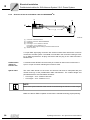
[1]
0,1
0,1
0,1
[2]
[3]
64018AXX
[1] Installation of primary (mounting plate)
[2] Installation of secondary (basic body, e. g machine base)
[3] Air gap
Shape and position tolerances in reference to 1000 mm length
The shape and position tolerances must be observed for the function of the SL2 linear
motor. Depending on the used measuring system, it may be necessary to have a greater
accuracy of the mounted parts for safe operation. These accuracies are sufficient for the
functionality of the AL1H encoder system.
These shape and position tolerances will have to be observed in operating mode at
steady-state temperature of the SL2 linear motor. Also take into consideration the influence of the loads applied by the customer.
5.3
32
Required tools
•
Standard tools
•
Operation with conductor end sleeves: Crimping tool and conductor end sleeves
(without insulation shroud, DIN 46228, Part 1, Material E-Cu)
•
Crimping tool for plug connectors
Operating Instructions – SL2 Synchronous Linear Motors
Mechanical Installation
Installing SL2-Basic
5.4
Installing SL2-Basic
5.4.1
Before you start
Check that
•
The entries on the nameplate of the drive and/or the output voltage of the inverter
match the voltage supply system,
•
The drive is undamaged (no damage caused by transportation or storage)
•
Ensure that the following requirements have been met:
5
– Ambient temperature between +5 °C and +40 °C1)
– No harmful oils, acids, gases, vapors, radiation etc. in the vicinity
– Installation altitude max. 1000 m above sea level1)
NOTE
Start with the installation of the primary. Install the secondaries once all other installation work has been completed, immediately prior to startup of the drive. Observe the
safety notes about handling the secondaries (see chapter 2).
5.4.2
Preparing the SL2-Basic primary for installation
[1]
53349AXX
Mounting surfaces [1]:
The mouting surfaces of the primary were treated with an anti-corrosion agent at the
factory. Do not remove this protection layer. Before installing the surface, wipe the
surface with a lint free cloth to remove any dust, dirt, etc. clinging to the surface.
Retaining screws:
Use all M5 tapped holes in the mouting surface for retaining purposes. Use screws of
size M5, strength class 8.8 or higher. The minimum depth of engagement is 8 mm. The
tightening torque is always 6 Nm and may not be exceeded, even with screws of a
higher strength class.
1) Observe the derating data in chapter 10.4 of the catalog.
Operating Instructions – SL2 Synchronous Linear Motors
33
Mechanical Installation
Installing the SL2-Advance System and SL2-Power System
5
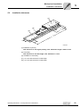
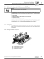
5.5
Installing the SL2-Advance System and SL2-Power System
[4]
[3]
[2]
[1]
56147AXX
[1]
[2]
[3]
[4]
Guide carriage
Fixed bearing end
Floating bearing end
End plate
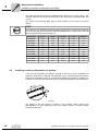
The SL2-Advance System and SL2-Power System are screwed onto the guide carriage
[1]. Bores for cylinder screws to DIN EN ISO 4762 (previously DIN 912) are provided for
this purpose on the primary housing (screws are not included in the scope of delivery).
NOTE
Guide systems available for SL2-Advance System and SL2-Power System are listed in
chapter 10.10.
This screw connection essentially determines the mechanical load capacity of the
primary. Use screws of strength class 8.8.
Deviating loads of the screw connection must be determined in accordance with the
standard calculation procedures used in mechanical engineering (VDI 2230). The
customer loads and design of the guide system are included in the calculation.
The calculation basis must not exceed a maximum interface pressure under the screw
head of 230 N/mm². The friction value μhead under the screw head is 0.15.
Type
SL2-050
SL2-100
SL2-150
34
Size of screw
Tightening torque
[Nm]
Number of screws
VS
S
M
ML
Fixed bearing end [2]
M6x12
10
8
8
12
12
Floating bearing end [3]
M6x16
10
8
8
12
12
Fixed bearing end [2]
M8x16
20
8
8
12
12
Floating bearing end [3]
M8x20
20
8
8
12
12
Fixed bearing end [2]
M8x16
20
8
8
12
Floating bearing end [3]
M8x20
20
8
8
12
Operating Instructions – SL2 Synchronous Linear Motors
Mechanical Installation
Installing the SL2-Advance System and SL2-Power System
5.5.1
Prerequisite for assembly
First assemble the guide system including the guide carriage according to the manufacturer’s specifications. Note in particular the requirements regarding the accuracy of the
mounting surfaces (→ chapter. 5.2 "Installation tolerances")
5.5.2
Starting the installation
5
WARNING
Improper installation may result in hazardous situations.
Severe or fatal injuries!
•
5.5.3
Install the secondaries once all other installation work has been completed,
immediately prior to startup of the drive. Observe the safety notes about handling
the secondaries in the individual chapters.
Installing the primary
1. Wipe the surface of the primary lightly with a lint free cloth to remove any dust, dirt,
etc.
2. Align the guide carriages [1] on the guide rails ( see figure on the previous page) so
that the primary can be installed.
3. Place the primary onto the guide carriage [1]. Use suitable hoists for heavy parts (see
chapter 2.1 Transportation).
4. Attach all the screws to connect the primary with the guide carriages [1]. Do not
grease or oil the screws.
NOTE
Use a magnetic hexagon socket tool to attach the screws. They prevent screws from
falling out in unfavorable mounting positions. If screws fall inside the primary housing,
it is essential that you remove them. The end plate [4] can be removed for easier
access (see illustration on the previous page).
5. First tighten the screws at the fixed bearing end [2] in accordance with the tightening
torque (see table on the previous page).
6. Then tighten the screws at the floating bearing end [3].
Operating Instructions – SL2 Synchronous Linear Motors
35
Mechanical Installation
Installing the SL2 secondaries
5
5.6
Installing the SL2 secondaries
5.6.1
Perparing the secondaries for installation
WARNING
Danger caused by magnetic field
Severe or fatal injuries!
•
Do not unpack parts until you are ready for installation.
Preparing installation of secondaries size 050-200
First prepare the M6 retaining threads in the machine base to install the secondaries.
Preparing installation of secondaries size 250
Parallel pins are additionally needed to install size SL2-S 250. Pin holes with a bore
diameter of 5 H7 mm must be provided in the machine base. Observe a distance tolerance of ± 0.02 mm for the bores.
Use cylinder pins according to ISO 2338-5m6 for securing by pins.
For blind holes we recommend to use parallel pins with internal thread according to
DIN 7979-5m6 to facilitate removing the pins in case of disassembly.
STOP
The pins have to be fitted securely in the bore to prevent them from coming loose during
linear motor operation. Please check for proper pin connection.
The mouting surfaces of the secondary were treated with an anti-corrosion agent at the
factory. Do not remove this protection layer. Before installing the surface, wipe the
surface with a lint free cloth to remove any dust, dirt, etc. clinging to the surface.
36
Operating Instructions – SL2 Synchronous Linear Motors
Mechanical Installation
Installing the SL2 secondaries
5.6.2
5
Installing the secondaries
Install the first part at one end of the travel section and work your way down in one
direction. The orientation of the first part can be random. The adjoining part will have the
same orientation. The north [1] (N) and south [2] (S) poles are identified on the secondaries (see following illustration). You can combine secondaries of different lengths.
[1]
[2]
53354AXX
[1] North pole
[2] South pole
Use all bores of the secondary for retaining purposes. Use screws of size M6, strength
class 8.8 or higher. The engagement depth and tightening torque (generally 10 Nm)
depend on the customer support structure.
Move primary over secondaries by hand prior to startup of drive to check for unhindered
operation.
Use non-magnetic testing devices, such as feeler gauges made of stainless steel,
aluminum, brass or copper sheets if you are planning to check the visible air gap.
DANGER
Risk of injury due to electric shock.
Induced voltages of up to 500 V can be generated by movement of the primary
(generator principle) even if the motor is not connected.
Severe or fatal injuries!
•
Only remove the protection cap on the power plug of the primary immediately
before connecting the power plug to the power supply.
Operating Instructions – SL2 Synchronous Linear Motors
37
Mechanical Installation
Installing the AL1H measuring system
5
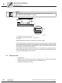
5.7
Installing the AL1H measuring system
STOP
•
It is essential that you read the manufacturer’s operating instructions provided with
the encoder system.
•
Note for installation of the measuring tape [2] that the end identified by a dot [5] is
stuck-on in the direction of the connecting plug.
[6]
[3]
[1]
[7]
[4]
[2]
[5]
56178AXX
[1]
[2]
[3]
[4]
[5]
[6]
[7]
Linear sensor
Measuring tape
Encoder mount-on components
Connection of the linear sensor
Identification of the installation direction of the measuring tape
Screw for primary housing/mount-on components
Screw for linear sensor/mount-on components
Use the M8x20 non-magnetic stainless steel screws provided to connect the linear
sensor/mount-on components [7] (tightening torque 16 Nm).
Tighten the M5x12 screws lightly to secure the primary housing/mount-on components
[6] (maximum tightening torque 5 Nm).
38
Operating Instructions – SL2 Synchronous Linear Motors
Mechanical Installation
Mechanical load capacity SL2-Advance and SL2-Power
5.8
5
Mechanical load capacity SL2-Advance and SL2-Power
STOP
Check the following points in each application.
The permitted mechanical load capacity of the entire linear drive system depends on the
size, position and type of the forces caused by the loads mounted by customers and the
permitted loads from:
•
Guide system
•
Retaining screws for guide carriages on the cooling unit
•
Cooling unit housing
•
Loads mounted via slots/T-slot nuts
However, to help with the selection, the permitted loads have been reduced to simple
applications and clear calculation models. Depending on the individual application,
greater loads may occur. Contact SEW-EURODRIVE for more information.
5.8.1
Guide systems
The detailed project planning process for the linear guide system must be performed
together with the manufacturer of the guide system and is not the responsibility of SEWEURODRIVE.
5.8.2
Housing of the motor cooling unit
Mz Fz
Mx
My
Fy
55389AXX
[Mx]
[My]
[Mz]
[Fy]
[Fz]
= Permitted load torque on the X axis
= Permitted load torque on the Y axis
= Permitted load torque on the Z axis
= Permitted force in Y direction
= Permitted force in Z direction
Operating Instructions – SL2 Synchronous Linear Motors
39
Mechanical Installation
Installing customer components on primary
5
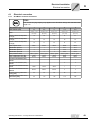
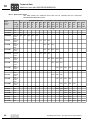
The table (see below) shows the permitted static loads on the entire primary. The
magnetic attraction forces between the primary and secondary are already taken into
account.
The values in the following table apply to both directions for the forces and torque
ratings.
STOP
The housing is only allowed to be subjected to one load value. If several forces/torques
act on the housing at the same time, SEW-EURODRIVE can calculate the exact load
bearing capacity of the motor cooling unit.
5.9
Motor type
Mx [Nm]
Fy [N]
My [Nm]
Fz [N]
Mz [Nm]
SL2-050VS
1500
1600
2500
12000
150
SL2-050S
1700
1800
4500
14000
220
SL2-050M
2500
2800
10000
20000
550
SL2-050ML
2800
3000
16000
20000
800
SL2-100VS
3400
3100
3200
12000
200
SL2-100S
3800
3400
8000
14000
400
SL2-100M
5500
5300
20000
20000
1000
SL2-100ML
5800
5700
32000
20000
1500
SL2-150S
5300
4000
10000
19000
400
SL2-150M
6000
4600
20000
26000
700
SL2-150ML
8500
6500
45000
32000
1800
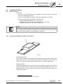
Installing customer components on primary
T-slot nuts are inserted in the primary housing at the factory for the installation of
customer components. If required, the distribution of the T-slot nuts within the primary
housing can be adapted. To do so, unscrew the end plate [4] (see figure in chapter 5.5),
insert the T-slot nuts in the required slot using a spring and screw the end panel plate on.
L
Fz
Fx
Fy
55065AXX
The design of the slot system is based on the modular profile system from
Bosch/Rexroth so that components from this modular system or similar modular
systems can be used.
40
Operating Instructions – SL2 Synchronous Linear Motors
Mechanical Installation
Installing customer components on primary
5
Permitted static load for the slot:
In direction
Fz
12000 N
In direction
Fx
1000 N
In direction
Fy
1000 N
(plastic deformation starts)
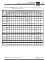
NOTE
Rule of thumb: 1000 N (≈ 100 kg) per T-slot nut in every direction
As long as the minimum distance [L] between the T-slot nuts is observed, the T-slot nuts
can be distributed as required within the customer mounting surface.
Motor type
Number of T-slot nuts enclosed
Min. distance (L) between the Tslot nuts [mm]
SL2-050VS
6
70
SL2-050S
8
80
SL2-050M
10
90
SL2-050ML
10
90
SL2-100VS
8
70
SL2-100S
8
80
SL2-100M
10
90
SL2-100ML
10
90
SL2-150S
10
80
SL2-150M
12
90
SL2-150ML
14
90
To make it easier for customers to install/remove loads, each cooling unit comes
equipped with pin holes for positioning. Additionally, the T-slot nuts are secured to
ensure that they do not shift.
Any other loads acting on the screw connection of the T-slot nuts must be determined
in accordance with the standard calculation procedures used in mechanical engineering
(VDI 2230). The customer loads and design of the mount-on components are included
in the calculation.
Generally, the permitted load of the primary is limited by the screw itself.
Operating Instructions – SL2 Synchronous Linear Motors
41
Electrical Installation
Installing customer components on primary
6
6
Electrical Installation
DANGER
Risk of injury due to electric shock.
Severe or fatal injuries.
•
Strictly observe the safety notes in the individual chapters.
•
When motors are powered from inverters, you must adhere to the wiring instructions issued by the inverter manufacturer. Adhere to the operating instructions for
the inverter.
NOTE
A bag containing the following information is attached to the motor:
•
Safety notes
•
Wiring diagram
Comply with this information.
42
Operating Instructions – SL2 Synchronous Linear Motors
Electrical Installation
Electrical connection
6.1
Electrical connection
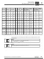
6.1.1
SL2-Basic electrical connection
6
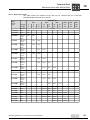
STOP
The current carrying capacity only applies to the SL2-Basic design with standard cable
length 1m.
Cable extension type
Outer diameter [mm]
1
2
3
4
5
9.6
10.8
13
17.5
20.5
4 x 1.5 + 1 x
(2 x 0.5)
4 x 2.5 + 1 x
(2 x 0.5)
4x4+1x
(2 x 0.5)
4x6+1x
(3 x 1.5)
4 x 10 + 1 x
(3 x 1.5)
Load A at ambient temperature
30 °C [A]
18
26
34
44
61
Load A at ambient temperature
40 °C [A]
16
23
30
40
55
Load A at ambient temperature
60 °C [A]
12
17
24
31
43
Color of power cores
Black
Black
Black
Black
Black
Identification phase U
1
1
1
U/L1
U/L1
Identification phase V
2
2
2
V/L2
V/L2
Cores
Identification phase W
3
3
3
W/L3
W/L3
Color protective earth
Yellow / green
Yellow / green
Yellow / green
Yellow / green
Yellow / green
Color of thermistor core (TF1)
White
White
White
Black
Black
Color of thermistor core (TF2)
Brown
Brown
Brown
Black
Black
Thermistor identification (TF1)
PTC140
-
-
-
1
1
Thermistor identification (TF2)
PTC140
-
-
-
2
2
Thermistor identification KTY-84
Anode
White
White
White
1
1
Thermistor identification KTY-84
Kathode
Brown
Brown
Brown
2
2
Minimum bending radius fixed
routing [mm]
20
22
26
53
62
Minimum bending radius at constant motion [mm]
96
110
130
175
205
Operating Instructions – SL2 Synchronous Linear Motors
43
Electrical Installation
Electrical connection
6
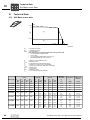
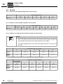
6.1.2
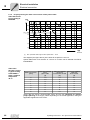
Project planning for cable cross section of the power cable
Cable dimensioning according to
EN 60402
l [m]
150
25 mm²
130
16 mm²
10 mm²
110
6 mm²
100
[1]
4 mm²
90
2,5 mm²
1,5 mm²
70
50
30
10
0
20
30
40
50
60
70
80
90
100
I [A]
55258AXX
[1]
Max. permitted cable length to SEW specification = 100 m
The diagram (see figure above) is the basis for chapters 4.2 and 4.3.
Hybrid cables with cross sections of 1.5 mm2 to 10 mm2 can be ordered from SEWEURODRIVE.
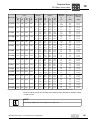
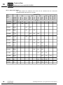
Cable load
through current I
in [A] according
to EN 60204-1
table 5, ambient
temperature
40 °C
Cable cross section
[mm2]
Three-core sheathed
line in
pipe or cable
[A]
Three-core sheathed
line on top
of one another on wall
[A]
Three-core sheathed
cable next
to one another
[A]
1.5
12.2
15.2
16,1
2.5
16.5
21
22
4
23
28
30
6
29
36
37
10
40
50
52
16
53
66
70
25
67
84
88
35
83
104
114
These data are merely recommended values and are no substitute for detailed
project planning of the supply cables depending on the actual application, taking the
applicable regulations into account!
44
Operating Instructions – SL2 Synchronous Linear Motors
Electrical Installation
Electrical connection
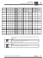
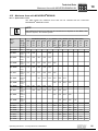
6.1.3
6
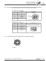
Pin assignment of the power connection for the SL2-Advance System and SL2 -Power System
The following pin assignments are described as viewed onto the motor.
Size SL2-P050 and design AVX0
Pin
Assigned
1
U
4
V
3
W
2
PE
A
TF1/KTY-A
B
TF2/KTY-K
C
n.c.
D
n.c.
Plug connector
BEGA 089
W
D
TF2/KTY-K
PE
3
C
4
2
V
B
A
1
U
TF1/KTY-A
Size SL2-P100, SL2-P150
6.1.4
Pin
Assigned
U1
U1
V1
V1
W1
W1
PE
Green / yellow
3
n.c
4
(TF1)/KTY-A
5
(TF2)/KTY-K
Plug connector
C148U connector with socket contacts
Pin assignment for the power supply to the fan in the SL2-Power System
[2]
[1]
56377AXX
[1] +24 V
[2] Grounding
Operating Instructions – SL2 Synchronous Linear Motors
45
Electrical Installation
Electrical connection
6
6.1.5
Safety notes
EMC measures
SEW-EURODRIVE SL2 synchronous linear motors are designed for use as components for installation in machinery and systems. The designer of the machine or system
is responsible for complying with the EMC Directive 89/336/EEC. For more detailed
information on this subject, refer to the SEW publications:
"Drive Engineering Practical Implementation Volume 7, Project Planning for
Drives" and "Drive Engineering Practical Implementation Volume 9, EMC in Drive
Engineering".
Encoder
connection
Observe the following instructions when connecting an encoder:
•
Use a shielded cable with twisted pair conductors only.
•
Connect the shield to the PE potential on both ends over a large surface area.
•
Route signal cables separately from power cables or brake cables (min. distance
200 mm).
Thermal motor
protection
STOP
Risk of unwanted axis movements due to interference from parasitic signals (EMC) via
the motor cable.
When an older MOVIDRIVE® compact MCH inverter is used, SEW-EURODRIVE
strongly recommends that you use an external TF evaluation unit (e.g. EMT6-K from
Möller or 3RN1011 from Siemens).
Under extreme EMC conditions, the TF line can be wound, for example with 5 windings
around a ferrite ring choke or an HD002 output choke.
STOP
If you use a KTY temperature sensor (KTY84...140), it is essential that you contact
SEW-EURODRIVE.
STOP
If you use inverters from another manufacturer, contact SEW-EURODRIVE. This is to
ensure that thermal motor monitoring is ensured for the customer’s installation.
46
Operating Instructions – SL2 Synchronous Linear Motors
Electrical Installation
Prefabricated cables for SL2-Advance System / SL2 -Power System
6.2
6
Prefabricated cables for SL2-Advance System / SL2 -Power System
NOTE
Cables with line cross sections of 1.5 and 2.5 mm2 have low capacitive properties for
operation on inverters. Older cables without low capacitive properties have another
outer diameter.
6.2.1
Prefabricated power cables
For the motor designs
•
SL2-Advance System
•
SL2-Power System
SEW-EURODRIVE offers prefabricated power and feedback cables from 1 m to 100 m
for straightforward and reliable connection.
The opposite cable end is fitted with cable lugs (for power cables) or conductor end
sleeves. The shielding is connected to the mating connector.
Prefabricated power cables are used to connect the:
6.2.2
•
Motor power
•
Motor protection (TF or KTY)
Prefabricated feedback cable
SEW-EURODRIVE offers a feedback cable for the AL1H linear measuring system. The
cable is fitted with plug connectors for connection to the encoder and the inverter.
The cables are only available as cable carrier cables. Cables from the company Nexan
are used.
6.2.3
SL2 unit designation
Power cables of the SL2-P050... motors correspond to the brakemotor cables of the
CM71 motor series with an SB71-74 round plug connector.
The power cables for the motor sizes SL2-P100 and SL2-P150 correspond to the brake
motor cables of the CM motor series with SB51-59 plug connectors.
NOTE
Observe the data given in the specification in chapters 6.1 and 6.2.
Operating Instructions – SL2 Synchronous Linear Motors
47
Electrical Installation
Prefabricated cables for SL2-Advance System / SL2 -Power System
6
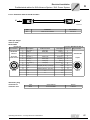
6.2.4
Structure of power cables for SL2-050 motors and AVX0 design
[5]
[1]
[6]
[2]
500 ±
X
5
[3]
[4]
55778AXX
[1]
[2]
[3]
[4]
[5]
[6]
48
Connector: Intercontec BSTA 078
SEW-EURODRIVE logo printed on cable
Nameplate
Line length ≤ 10 m: Tolerance +200 mm
Line length ≥ 10 m: Tolerance +2 %
Permitted cable length according to the technical documents
Prefabricated cable end for inverter
Required loose parts are supplied with the cable
Shielding 20 mm, pulled back approximately + 5 mm
Prefabricated
cables for motor
side
The power cables on the motor side consist of an 8-pin plug connector and socket
contacts.
Prefabricated
cables for
inverter end
The individual cable cores of the power cables are exposed and the shield is prepared
for connection in the control cabinet. The cable for the inverter end has yet to be assembled. The loose parts required are supplied with the cable in a separate bag.
Loose parts
The following loose parts are supplied in accordance with the core cross sections for
connection to the power terminals on the inverter:
The shield is connected in the connector housing according to EMC requirements. All
plug connectors seal the plug on the cable end with a lamellar seal and ensure cable
relief according to EN 61884.
Bag no.
Contents
1
4 x conductor end sleeves 1.5 mm2 , insulated
4 x M6 U-shaped cable lugs 1.5 mm2
2
4 x conductor end sleeves 2.5 mm2 , insulated
4 x M6 U-shaped cable lugs 2.5 mm2
3
4 x conductor end sleeves 4 mm2 , insulated
4 x M6 U-shaped cable lugs 4 mm2
4 x M10 U-shaped cable lugs 4 mm2
Operating Instructions – SL2 Synchronous Linear Motors
Electrical Installation
Prefabricated cables for SL2-Advance System / SL2 -Power System
6.2.5
6
Structure of power cables for SL2-100 and SL2-150 motors
[1]
[5]
[2]
X
[6]
500 ±5
[3]
[4]
55779AXX
[1]
[2]
[3]
[4]
[5]
[6]
Connector: Amphenol
SEW-EURODRIVE logo printed on cable
Nameplate
Line length ≤ 10 m: Tolerance +200 mm
Line length ≥ 10 m: Tolerance +2 %
Permitted cable length according to the technical documents
Prefabricated cable end for inverter
Required loose parts are supplied with the cable
Shielding 20 mm, pulled back approximately + 5 mm
Prefabricated
cables for motor
side
The power cables on the motor end have a 6-pin EMC Amphenol plug connector and
socket contacts.
Prefabricated
cables for
inverter end
The individual cable cores of the power cables are exposed and the shield is prepared
for connection in the control cabinet. The cable for the inverter end has yet to be assembled. The loose parts required are supplied with the cable in a separate bag.
Loose parts
The following loose parts are supplied in accordance with the core cross sections for
connection to the power terminals on the inverter:
The shield is connected in the connector housing according to EMC requirements. All
plug connectors seal the plug on the cable end with a lamellar seal and ensure cable
relief according to EN 61884.
Bag no.
Contents
1
4 x conductor end sleeves 1.5 mm2 , insulated
4 x M6 U-shaped cable lugs 1.5 mm2
2
4 x conductor end sleeves 2.5 mm2 , insulated
4 x M6 U-shaped cable lugs 2.5 mm2
3
4 x conductor end sleeves 4 mm2 , insulated
4 x M6 U-shaped cable lugs 4 mm2
4 x M10 U-shaped cable lugs 4 mm2
4
4 x M6 U-shaped cable lugs 6 mm2
4 x M10 U-shaped cable lugs 6 mm2
5
4 x M6 U-shaped cable lugs 10 mm2
4 x M10 ring-type cable lugs 10 mm2
Operating Instructions – SL2 Synchronous Linear Motors
49
Electrical Installation
Prefabricated cables for SL2-Advance System / SL2 -Power System
6
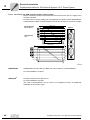
6.2.6
Structure of the AL1H feedback cable for MOVIDRIVE® B
[1]
[2]
[5]
X
[3]
[4]
56488AXX
[1]
[2]
[3]
[4]
[5]
Connector: Intercontec ASTA
Printed on connector: SEW-EURODRIVE
Nameplate
Line length ≤ 10 m: Tolerance +200 mm
Line length ≥ 10 m: Tolerance +2 %
Permitted cable length according to the technical documents
Sub-D connector
A 12-pin EMC signal plug connector with socket contacts from Intercontec is used to
connect the encoder system. The shield is connected in the connector housing according to EMC requirements. All plug connectors seal the plug on the cable end with a
lamellar seal.
Prefabricated
cables for
inverter end
A commercial sub-D EMC connector with pin contacts is used on the inverter end. A
9-pin or 15-pin connector matching the inverter is used.
Hybrid cable
The outer cable sheath on the motor and inverter end bears a nameplate with part
number and logo of the prefabricated cable manufacturer. The ordered length and
permitted tolerance are interrelated as follows:
•
Line length ≤ 10 m: Tolerance 200 mm
•
Line length ≥ 10 m: Tolerance +2 %
NOTE
Refer to the system manual of the inverter for determining the maximum cable length.
Make sure that an EMC-compliant environment is maintained during project planning.
50
Operating Instructions – SL2 Synchronous Linear Motors
Electrical Installation
Prefabricated cables for SL2-Advance System / SL2 -Power System
6.2.7
6
Structure of the AL1H feedback cable for MOVIAXIS®
[4]
500
[1]
[2]
X
[3]
Y
63286AXX
[1]
[2]
[3]
[4]
Connector: Intercontec ASTA
Nameplate
Sub-D connector
Screw terminal
A 12-pin EMC signal plug connector with socket contacts from Intercontec is used to
connect the encoder system. The shield is connected in the connector housing according to EMC requirements. All plug connectors seal the plug on the cable end with a
lamellar seal.
Prefabricated
cables for
inverter end
Hybrid cable
A sub-D EMC connector with pin contacts is used on the inverter end. A 9-pin or 15-pin
connector matching the inverter is used.
With MOVIAXIS®, the temperature sensor of the linear motor can be connected using
screw terminals. The sensor can be evaluated via encoder input.
The outer cable sheath on the motor and inverter end bears a nameplate with part
number and logo of the prefabricated cable manufacturer. The ordered length and
permitted tolerance are interrelated as follows:
•
Line length ≤ 10 m: Tolerance 200 mm
•
Line length ≥ 10 m: Tolerance +2 %
NOTE
Refer to the system manual of the inverter for determining the maximum cable length.
Make sure that an EMC-compliant environment is maintained during project planning.
Operating Instructions – SL2 Synchronous Linear Motors
51
Electrical Installation
Prefabricated cables for SL2-Advance System / SL2 -Power System
6
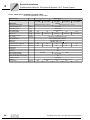
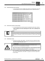
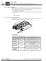
6.2.8
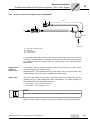
Pin assignment of power cable SL2-050 and AVX0 design
X
5
500 ±
54620AXX
The customer assembles the cable with a Phoenix plug connector. The connector can
be cut off because it is not required for the TF connection.
Plug connector
Pin
BSTA 078
1
4
W
P
V
C
4
2
1
Assigned
Black with white lettering U, V,
W
2
Green/yellow
PE
TF1/KTY-A
A
Black 1
TF1/KTY-A
A
U
View X
Extra
V
TF2/KTY-K
B
Contact type
U
3
D
3
Core identification
W
B
Black 2
TF2/KTY-K
C
Black 3
n.c.
D
–
n.c.
Cut off Phoenix connector
Bag of loose
parts
Ground in
control cabinet
Part no.
Installation type
LC1)
SB71 / SB81
4 x 1.5 mm2
3 x 1 mm2
(AWG 16)
(AWG 17)
0590 631 8
Cable carrier
installation
X
SB72 / SB82
4 x 2.5 mm2 (AWG 14)
3 x 1 mm2 (AWG 12)
0590 632 6
Cable carrier
installation
X
SB74 / SB84
4 x 4 mm2 (AWG 12)
3 x 1 mm2 (AWG 17)
0590 484 6
Cable carrier
installation
Plug connector type
Number of cores and line cross section
1) Cable with low capacitance characteristics (LC = low capacity).
Alternative plug
connector at
customer end
Plug connectors for power supply with socket contacts (complete).
Type
Number of cores and line cross section
Part no.
SB71 / SB81
4 x 1.5 mm2 (AWG 16)
3 x 1 mm2 (AWG 17)
0198 919 7
SB72 / SB82
4 x 2.5 mm2 (AWG 14)
3 x 1 mm2 (AWG 12)
0198 919 7
SB74 / SB84
4 x 4 mm2 (AWG 12)
3 x 1 mm2 (AWG 17)
0199 163 9
NOTE
The pin assignment deviates from SEW servomotor cables for DS and CMP motors.
52
Operating Instructions – SL2 Synchronous Linear Motors
Electrical Installation
Prefabricated cables for SL2-Advance System / SL2 -Power System
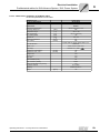
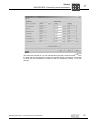
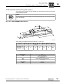
6.2.9
6
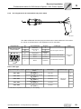
Pin assignment for SL-100 and SL2-150 power cables
X
500 ±5
54613AXX
The cable is fitted with a Phoenix plug connector at the control cabinet end. The connector can be cut off because it is not required for the TF connection.
Plug connector
C148U connector with
socket contacts
5
4
Pin
U1
V1
W1
Core identification
Assigned
Black with
white lettering
U, V, W
U
Contact type
V
Cut-off, length ca. 250 mm
W
PE
Green/yellow
(protective
earth)
3
Black 1
n.c
4
Black 2
TF1/KTY-A
5
Black 3
TF2/KTY-K
3
Extra
Ground in control cabinet
Bag of loose
parts
Cut off Phoenix connector
View X
Power cable type
Plug connector type, complete
Number of cores and line cross
section
Part number
SB51 / SB61
4 x 1.5 mm2 (AWG 16) + 3 x 1.0
mm2 (AWG 17)
1333 116 7
X
SB52 / SB62
4 x 2.5 mm2 (AWG 12) + 3 x 1.0
mm2 (AWG 17)
1333 117 5
X
SB54 / SB64
4 x 4 mm2 (AWG 10) + 3 x 1.0
mm2 (AWG 17)
199 194 9
SB56 / SB66
4 x 6 mm2 (AWG 10) + 3 x 1.5
mm2 (AWG 16)
199 196 5
SB59 / SB69
4 x 10 mm2 (AWG 10) + 3 x 1.5
mm2 (AWG 17)
199 198 1
Installation type
LC1)
Cable carrier
installation
1) Cable with low capacitance characteristics (LC = low capacity).
Operating Instructions – SL2 Synchronous Linear Motors
53
Electrical Installation
Prefabricated cables for SL2-Advance System / SL2 -Power System
6
6.2.10 Pin assignment for SL-100 and SL2-150 power extension cables
X
Y
57074AXX
Pin assignment
for extension
cables
Plug connector
C148U adapter with pin
contacts
5
4
3
Pin
Core identification
Pin
W1
Black with
white lettering
U, V, W
U1
PE
Green/yellow
PE
n.c
Black 1
n.c
4 TF1/KTY-A
Black 2
4 TF1/KTY-A
5 TF1/KTY-K
Black 3
5 TF1/KTY-K
U1
V1
Plug connector
C148U connector with
socket contacts
V1
W1
View X
View Y
The extension cable has the same pin assignment as all other contacts.
Power extension
cable types
Plug connector
type, complete
Number of cores and line
cross section
Part number
SK51 / SK61
4 x 1.5 mm2 (AWG 16) + 3 x
1.0 mm2 (AWG 17)
1333 120 5
X
SK52 / SK62
4 x 2.5 mm2 (AWG 12) + 3
x 1.0 mm2(AWG 17)
1333 121 3
X
SK54 / SK64
4 x 4 mm2 (AWG 10) + 3 x
1.0 mm2 (AWG 17)
0199 204 X
SK56 / SK66
4 x 6 mm2 (AWG 10) + 3 x
1.5 mm2 (AWG 16)
0199 206 6
SK59 / SK69
4 x 10 mm2 (AWG 10) + 3 x
1.5 mm2 (AWG 17)
0199 208 2
Installation type
LC1)
Cable carrier
installation
1) Cable with low capacitance characteristics (LC = low capacity).
Alternative plug
connector at
customer end
54
Plug connectors for power supply with socket contacts (complete).
Type
Cross sections
Part no.
SB51 / SB61
4 x 1.5 mm2 (AWG 16) + 3 x 1.0 mm2 (AWG 17)
199 142 6
SB52 / SB62
4 x 2.5 mm2 (AWG 12) + 3 x 1.0 mm2 (AWG 17)
199 143 4
SB54 / SB64
4 x 4 mm2 (AWG 10) + 3 x 1.0 mm2 (AWG 17)
199 144 2
SB56 / SB66
4 x 6 mm2 (AWG 10) + 3 x 1.5 mm2 (AWG 16)
199 145 0
SB59 / SB69
4 x 10 mm2 (AWG 10) + 3 x 1.5 mm2 (AWG 17)
199 146 9
Operating Instructions – SL2 Synchronous Linear Motors
Electrical Installation
Prefabricated cables for SL2-Advance System / SL2 -Power System
6
6.2.11 Cable for AL1H encoder MOVIDRIVE®
.
X
Y
54629AXX
Type
SL2
Installation
Part number
®
Cable carrier installation (MOVIDRIVE B)
0595 151 8
Cable pin assignment for feedback cables
Connecting MOVIDRIVE® MDX..B
Encoder end
Plug connector
Contact
Description
no.
Cable core color
Description Contact no. Plug connector
1
S3 (cosine -)
Blue (BU)
S3 (cosine -)
9
ASTA021FR
2
Data (+)
Black (BK)
Data (+)
4
198 921 9
3
n. c.
n. c.
3
4
n. c.
n. c.
5
12-pin with
socket contacts
8
9
1
E
7 12
6
2
10 3
11
5 4
View X
5
S2 (sine +)
Yellow (YE)
S2 (sine +)
2
6
S4 (sine -)
Green (GN)
S4 (sine -)
10
7
Data (-)
Violet (VT)
Data (-)
12
8
S1 (cosine +)
Red (RD)
S1 (cosine +)
1
9
n. c.
10
GND
11
n. c.
12
Us
Grey/pink (GY-PK ) / pink (PK)
red/blue (RD-BU) / gray (GY)
n. c.
6
GND
8
n. c.
7
Sub-D 15-pin
9
15
1
8
Us
15
n. c.
n. c.
n. c.
11
MOVIDRIVE B
n. c.
n. c.
n. c.
13
View Y
n. c.
n. c.
n. c.
14
Operating Instructions – SL2 Synchronous Linear Motors
®
55
Electrical Installation
Prefabricated cables for SL2-Advance System / SL2 -Power System
6
6.2.12 Cable for AL1H encoder MOVIAXIS®
Using the following cable, also the temperature switch of the linear motor can be
connected to the encoder input. If this is not necessary, you can use the previously
described MOVIDRIVE® cable
X
Y
63627AXX
Type
Installation
Part number
SL2
Cable carrier installation
1333 224 4
Cable pin assignment for feedback cables
Connecting MOVIDRIVE® MDX..B
Encoder end
Plug connector
Contact no. Description
Cable core color
Description Contact no. Plug connector
1
S3 (cosine -)
Blue (BU)
S3 (cosine -)
9
ASTA021FR
2
Data (+)
Black (BK)
Data (+)
4
198 921 9
3
n. c.
n. c.
3
4
n. c.
n. c.
5
5
S2 (sine +)
Yellow (YE)
S2 (sine +)
2
6
S4 (sine -)
Green (GN)
S4 (sine -)
10
7
Data (-)
Violet (VT)
Data (-)
12
8
S1 (cosine +)
Red (RD)
S1 (cosine +)
1
9
n. c.
10
GND
12-pin with
socket contacts
8 9 1
7 12 10
2
11
6
3
5
4
11
n. c.
12
Us
View X
Grey/pink (GY-PK ) / pink (PK)
red/blue (RD-BU) / gray (GY)
n. c.
6
GND
8
n. c.
7
Us
15
n. c.
n. c.
n. c.
11
n. c.
n. c.
n. c.
13
Sub-D 15-pin
View Y
n. c.
1
2
3
56
1
TF/TH/KTY+
BN
TF/TH/KTY+
14
2
TF/TH/KTY-
WH
TF/TH/KTY-
6
3
Shielding
PE
Operating Instructions – SL2 Synchronous Linear Motors
Electrical Installation
Prefabricated cables for SL2-Advance System / SL2 -Power System
6
6.2.13 Extension cable for AL1H encoders
Y
X
63607AXX
Type
Installation
Part number
SL2
Cable carrier installation
1333 387 9
Cable pin assignment for feedback cables
Connecting MOVIDRIVE® MDX..B
Encoder end
Plug connector
Contact no. Description
Cable core color
Description Contact no. Plug connector
1
S3 (cosine -)
Blue (BU)
S3 (cosine -)
1
ASTA021FR
2
Data (+)
Black (BK)
Data (+)
2
198 921 9
3
n. c.
n. c.
3
4
n. c.
n. c.
4
5
S2 (sine +)
Yellow (YE)
S2 (sine +)
5
6
S4 (sine -)
Green (GN)
S4 (sine -)
6
7
Data (-)
Violet (VT)
Data (-)
7
8
S1 (cosine +)
Red (RD)
S1 (cosine +)
8
9
n. c.
10
GND
12-pin with
socket contacts
8 9 1
7 12 10
2
11
6
3
5
4
View X
11
n. c.
12
Us
Grey/pink (GY-PK ) / pink (PK)
Red/blue (RD-BU) / gray (GY)
n. c.
9
GND
10
n. c.
11
Us
12
n. c.
n. c.
n. c.
n. c.
n. c.
n. c.
AKUA020 MR
12-pole
View Y
n. c.
Alternative plug
connector at
customer end
Type
Cross sections
Part no.
ALH1
6 x 2 x 0.25 mm2
01986732
Operating Instructions – SL2 Synchronous Linear Motors
57
Electrical Installation
Prefabricated cables for SL2-Advance System / SL2 -Power System
6
6.2.14 Cable carrier installation of power cables
Technical specifications of the cable
Installation type
Cable carrier
4 x 1.5 mm2 +
3 x 1 mm2
Cable cross sections
4 x 2.5 mm2 +
3 x 1 mm2
Manufacturer
4 x 10 mm2 +
3 x 1.5 mm2
PSL(LC)C11Y-J 4x...+3A.../C
[VAC]
PSL11YC11Y-J 4x... +3A.../C
600 / 1000
Temperature range
[°C]
–20 to + 60
Max. temperature
[°C]
+ 90 (conductor)
Min. bending radius
[mm]
150
170
155
175
200
Diameter D
[mm]
15.0 ±1.4
16.2 ±0.7
15.3 ±0.5
17.4 ±0,5
20.5 ±0.5
Maximum acceleration
[m/s2]
20
[m/min]
200 at max. travel distance of 5 m
Max. velocity
Core identification
BK with lettering WH + GN/YE
Sheath color
Orange similar to RAL 2003
Approval(s)
DESINA / VDE / UL /
Capacitance core / shielding
[nF/km]
105
105
170
170
170
Capacitance core / core
[nF/km]
65
65
95
95
95
Halogen-free
Yes
Silicone-free
Yes
CFC-free
Yes
Inner insulation (cable)
Polyolefin
TPM
Outer insulation (sheath)
TPU (PURE)
Flame-retardant/self-extinguishing
Yes
Conductor material
E-Cu blank
Shielding
Weight (cable)
58
4 x 6 mm +
3 x 1.5 mm2
Nexans
Manufacturer designation
Operating voltage Uo/
4 x 4 mm2 +
3 x 1 mm2
Braided tinned Cu shield (optically covered > 85 %)
[kg/km]
280
380
410
540
750
Operating Instructions – SL2 Synchronous Linear Motors
Electrical Installation
Prefabricated cables for SL2-Advance System / SL2 -Power System
6
6.2.15 Cable carrier installation of feedback cable:
Technical specifications of the cable
Installation type
Cable carrier
Accessory designation
AL1H / ES1H
6 x 2 x 0.25 mm2
Cable cross sections
Manufacturer
Nexans
Manufacturer designation
Operating voltage Uo/
SSL11YC11Y6x 2 x 0.25
[VAC]
300
[°C]
–20 to + 60
Max. temperature
[°C]
+90 (on conductor)
Min. bending radius
[mm]
100
Diameter D
[mm]
9.8 ± 0.2
Maximum acceleration
[m/s2]
20
[m/min]
200
Temperature range
Max. velocity
WH/BN, GN/YE, GY/PK, BU/RD, BK/VT, GYPK/RD-BU
Core identification
Sheath color
Green similar to RAL 6018
Approval(s)
DESINA / UL / VDE /
Capacitance core/shielding
[nF/km]
Capacitance core / core
[nF/km]
100
55
Halogen-free
Yes
Silicone-free
Yes
CFC-free
Yes
Inner insulation (core)
PP
Outer insulation (sheath)
TPE-U
Flame-retardant/self-extinguishing
Yes
Conductor material
E-Cu blank
Shielding
Weight
Operating Instructions – SL2 Synchronous Linear Motors
Braided tinned Cu
[kg/km]
130
59
Electrical Installation
Prefabricated cables for SL2-Advance System / SL2 -Power System
6
6.2.16 Connecting non-SEW encoders with 5 V supply voltage
Many incremental encoders are not suited for direct connection to the 12 V supply of the
encoder evaluation.
Encoders with 5 V supply voltage can be supplied by the SEW inverters MOVIDRIVE®
or MOVIAXIS® if a DWI11A isused between inverter and encoder to convert the voltage.
max. 5 m
MOVIAXIS®
X13
1
6
2
7
3
8
9
5
BK
VT
쵰
max. 100 m
6
9
1
5
쵰
1
6
2
7
3
8
9
5
4*
쵰
DWI11A
X1: MOVIDRIVE
YE
GN
RD
BU
PK
GY
WH
BN
9
X2: Encoder
MOVIDRIVE®
DEH11Bx15
6
5
1
쵰
63296AXX
MOVIDRIVE®
HIPERFACE® encoder card type DEH X15 option: DWI11A X1: MOVIDRIVE®
For fixed installation: 8179573
MOVIAXIS®
Encoder connection X13: DWI11A X1
For fixed installation 13331531
The cable of MOVIDRIVE® can be used if not temperature sensor is additionally
evaluated on the encoder input.
60
Operating Instructions – SL2 Synchronous Linear Motors
Electrical Installation
Prefabricated cables for SL2-Advance System / SL2 -Power System
6
6.2.17 Power supply for the fan
[1]
55387AXX
[1]
M12 fan connection, 5-pole
The fans in power design are supplied via a commercially available 5-pole, M12 plug
connection with DC 24 V.
The power demand of the fan is as follows for
•
Sizes 50 to 100:
7.2 W
•
Size 150:
18 W
Customer connection cables are not available from SEW-EURODRIVE.
Suitable connection cables can be ordered from manufacturers, such as:
•
Phoenix CONTACT
•
Hirschmann
•
Harting
The following table is an extract from trailing cables available from Phoenix CONTACT:
Sensor/actuator cables, straight M12 socket, 3-pin (suitable for 5-pin connector)
Cable length
Article designation
Article number
3m
SAC-3P-3,0-PUR/M12FS
16 94 49 9
5m
SAC-3P-5.0-PUR/M12FS
16 83 51 0
10 m
SAC-3P-10,0-PUR/M12FS
16 93 03 4
Operating Instructions – SL2 Synchronous Linear Motors
61
6
Electrical Installation
Prefabricated cables for SL2-Advance System / SL2 -Power System
6.2.18 UWU51A switched-mode power supply
For the SL2-Power System design, the UWU51A switched-mode power supply is
available for powering the fan.
Input: 100 ... AC 240 V –6 % / +10 %, 50/60 Hz
Output: DC 24 V, 1 % / +2 %, 1.25 A
Connection: Terminal screws 0.2 ... 2.5 mm2, separable.
Degree of protection: IP20; attachment to EN 5022 support rail in the control cabinet
77
Part number: 0 187 441 1
38
76
86.5
64016AXX
62
Operating Instructions – SL2 Synchronous Linear Motors
Startup
Prefabricated cables for SL2-Advance System / SL2 -Power System
7
kVA
i
f
n
7
P Hz
Startup
DANGER
Risk of injury due to electric shock.
Severe or fatal injuries!
•
When motors are powered from inverters, you must adhere to the wiring instructions issued by the inverter manufacturer. Observe the operating instructions for
the inverter.
STOP
Improper startup may result in damages to the linear motor.
Potential damage to property!
•
Do closely observe the notes in this chapter.
•
Never work in the travel range when the machine is switched on.
•
Ensure free axis travel.
•
Check the final positions.
•
Check the linear measuring system prior to turning on the machine.
•
Limit the maximum power in the inverter.
•
Set the velocity limits in the inverter to small values.
•
SL2-Basic, SL2-Advance System and SL2-Power System are started up in the same
way.
•
Observe the safety notes in the individual chapters.
Operating Instructions – SL2 Synchronous Linear Motors
63
kVA
7
i
7.1
f
n
Startup
Prerequisites for startup
P Hz
Prerequisites for startup
Before startup,
make sure that
•
The primary moves along the entire travel distance easily, without collisions and free
from mechanical contact between the primary and secondary
•
All connections have been made properly
•
All protection devices have been installed correctly
•
All motor protection devices are active
•
The brake works correctly in hoists
•
You have a MOVIDRIVE® unit with firmware that supports SL2 linear motors, such
as MOVIDRIVE® B MDX...-0T (firmware 824 854 0.18 avaiable since week 14/2007),
or older inverter (special design -08;)
or
You have a MOVIAXIS® with firmware that supports SL2 linear motors (such as
MOVIAXIS® with firmware 21 or higher (available since February 2007)
7.2
•
There are no other sources of danger present
•
The MOVITOOLS® MotionStudio startup software is installed on your PC.
Commutation travel process
Unlike rotating systems, there is no mechanical connection between encoder system,
primary and secondary in SL2 linear motors.
This connection must be made during startup. The synchronous linear motor can then
be controlled directly by the inverter.
This process is referred to as commutation search or commutation travel.
This takes place
•
Once after "encoder adjustment" for absolute distance measuring systems
•
Every time the unit is turned on or reset in case of incremental distance measuring
systems.
Below a description of the standard communication travel type. How the communication
travel type is actived in the relevant inverter is described in the startup procedures for
the relevant MOVIDRIVE® and MOVIAXIS® inverters.
NOTE
Depending on the drive axis, more types are available on request if the standard
commutation travel type is not useful for your specific application.
64
Operating Instructions – SL2 Synchronous Linear Motors
Startup
Commutation travel process
7.2.1
kVA
i
f
n
7
P Hz
Commutation travel process
1. The linear motor moves to a random position. This can be a distance of between
0 mm to max. 16 mm in either direction from the start position. The linear motor stops
here for about one second.
-
≤ 16 mm
≤ 16 mm
+
53461AXX
2. The SL2 linear motor is moved in positive direction S = 32 mm with MOVIDRIVE®
(64 mm with MOVIAXIS®). It stops here for about one second.
s
-
+
64409AXX
3. The linear motor is moved in negative direction S = 32 mm with MOVIDRIVE®
(64 mm with MOVIAXIS®). It stops here for about one second.
-
S
+
64410AXX
®
With MOVIDRIVE , the linear motor repeats the commutation travel if it hits a hardware
limit switch during the travel. As a result, the linear motor moves to a new start position,
32 mm away from the limit switch and repeats commutation travel. For MOVIAXIS®, this
function was in preparation when this publication was printed.
You will then hear a quiet cracking noise and the linear motor switches from
controlled to automatic mode.
Operating Instructions – SL2 Synchronous Linear Motors
65
kVA
7
i
7.3
f
n
Startup
MOVIDRIVE® startup procedure
P Hz
MOVIDRIVE® startup procedure
Proceed as follows:
7.3.1
Parameterization
1.
Make sure that the inverter is in controller inhibit or 24 V mode.
2.
Execute startup for linear motors in MOVITOOLS® Shell starting with the factory
setting.
Refer to the online help for linear motor startup. Parameter setting is complete
once you have pressed the "Download" button twice and the below window is
displayed again. Exit the startup window at this point.
10394AEN
7.3.2
Checking encoder evaluation
3. Manually move the primary in one direction and observe parameter P003 (actual
position) in MOVITOOLS® Shell. Determine the positive direction of movement.
Then slide the linear motor once over the entire travel distance to check if the
encoder works correctly in all areas.
66
Operating Instructions – SL2 Synchronous Linear Motors
Startup
MOVIDRIVE® startup procedure
7.3.3
kVA
i
f
n
7
P Hz
Checking hardware limit switches
4. Set the parameters for the hardware limit switches, for example like in the figure,
and check their function by manually sliding the primary to the limit switches.
10396AEN
7.3.4
Activate drive limits for initial startup
5. For initial startup limit the maximum speed via parameter P302 (max. speed 1)
and the maximum force with parameter P304 (torque limit) so that the motor
cannot develop its full force and speed in case of an uncontrolled axis
movement.
NOTE
Do not limit the maximum force with parameter P303 (current limit 1) and do not limit
the maximum speed in the first dialog of the linear motor startup (this is the dialog that
appears after the illustration) because these parameters also affect internal system
values.
7.3.5
Commutation travel
6. Deactivate controller inhibit DI00=1. The linear motor now starts the above
described commutation process. See chapter 8 for troubleshooting of errors that
may occur during commutation travel.
WARNING
Under no circumstances may enable be present during commutation travel.
Risk of injury due to non-controlled axis movements.
•
Risk of injury due to non-controlled axis movements. This hazard does not exist any
longer since firmware 824 854 0.18 (available since week 14/2007) because this
situation is compensated by fault message "81 – start condition".
Once commutation travel is complete, the inverter sets variable H458 to 1. This
value will be evaluated later in the IPOSplus® program or in the PLC to permit the
inverter enable.
Operating Instructions – SL2 Synchronous Linear Motors
67
7
kVA
i
7.3.6
f
n
Startup
MOVIDRIVE® startup procedure
P Hz
Optimizing the axis
7. Write a short program to have the linear motor move cyclically between two positions.
Start the program and in the linear motor startup, carry out the point "V/X controller
startup only." If the linear motor moves correctly, set the current and force limits to
their original values (see point 5) and optimize the drive control loop via "Stiffness"
and the "Estimate" button as you would with rotary servomotors.
10529AEN
68
Operating Instructions – SL2 Synchronous Linear Motors
Startup
MOVIDRIVE® startup procedure
7.3.7
kVA
i
f
n
7
P Hz
Further settings
8.
With an absolute encoder, you will now execute the menu item "Encoder adjustment". The linear motor is then ready for operation immediately once the system
is turned on. If you do not execute the menu item "Encoder adjustment", an
absolute encoder will behave like an incremental encoder and the linear motor
will carry out a commutation travel once the controller inhibit has been removed
and the unit switched on.
9.
If you need a different positive encoder counting direction for your linear axis,
activate the reversal option for the motor rotation via parameter P350.
10. Remove the TF line from the inverter with enabled motor check whether TF
monitoring is responding (fault 31; TF trigger).
11. If the drive has an external brake, we recommend that you control it directly. The
brake is controlled using parameters P730 - P732.
12. For easier handling of sensor head replacement of the AL1H for servicing
purposes, set P948 "Automatic encoder detection" to OFF. If P948 is set to ON,
the inverter will automatically reset bit H473, bit 25 "LSM commutates" and
forces another commutation travel. P948 = OFF is recommended by SEW
because the absolute information is in the measuring tape and the actual
position and commutation information is maintained after sensor replacement.
Operating Instructions – SL2 Synchronous Linear Motors
69
kVA
7
i
7.4
f
n
Startup
MOVIDRIVE®: Calculating travel parameters
P Hz
MOVIDRIVE®: Calculating travel parameters
The inverter and the integrated IPOSplus® sequence control work internally with rotatory
values. During startup, the program determines conversion factors for linear values to
rotatory values.
10395AEN
Example:
A 100M-030 synchronous linear motor with HIPERFACE® encoder is to be operated
with the following travel information:
v = 1 m/s
s = 1000 mm
a = 5 m/s2
Based on the conversion factors shown above, the following rotary information will be
displayed in IPOSplus® or via fieldbus:
Speed = 0.0007 / velocity = 1428 rpm
Distance = 64 / 625 x 1000 = 102400 increments
Ramp = 2.000 / 5 = 0.4 s
70
Operating Instructions – SL2 Synchronous Linear Motors
Startup
MOVIDRIVE®: Calculating travel parameters
kVA
i
f
n
7
P Hz
10530AEN
The values are rounded off. You can calculate the exact rotary values for IPOSplus® from
the linear values in the last screen of the V/X controller startup. In the figure, a set speed
of 1500 rpm was calculated for IPOSplus® after the positioning velocity 1 m/s was
entered.
Operating Instructions – SL2 Synchronous Linear Motors
71
kVA
7
i
7.5
f
n
Startup
MOVIAXIS®: Startup procedure
P Hz
MOVIAXIS®: Startup procedure
Proceed as follows:
7.5.1
Parameterization
1. Make sure that the inverter is in controller inhibit or 24 V mode.
2.
Execute startup for linear motors in MOVITOOLS® MotionStudio starting with the
factory setting. The following dialogs show the typical settings for this process.
64391AEN
+
64392AEN
72
Operating Instructions – SL2 Synchronous Linear Motors
Startup
MOVIAXIS®: Startup procedure
kVA
i
f
n
7
P Hz
64393AEN
64394AEN
Operating Instructions – SL2 Synchronous Linear Motors
73
7
kVA
i
7.5.2
f
n
Startup
MOVIAXIS®: Startup procedure
P Hz
Checking encoder evaluation
3. Manually move the primary in one direction and observe index 9704, subindex 2
(actual position) in Shell of MOVITOOLS® MotionStudio. Determine the positive
direction of movement. Then slide the linear motor once over the entire travel
distance to check if the encoder works correctly in all areas.
7.5.3
Checking hardware limit switches
4. Set the hardware limit switch parameters and check their function by manually
sliding the primary to the limit switches.
7.5.4
Activate drive limits for initial startup
5. For initial startup, limit the maximum speed and the maximum force via the
application limit values so that the motor cannot develop its full force and speed
in case of a non-controlled axis movement.
64396AEN
74
Operating Instructions – SL2 Synchronous Linear Motors
Startup
MOVIAXIS®: Startup procedure
7.5.5
kVA
i
f
n
7
P Hz
Commutation travel
64397AEN
6. The FCB18 encoder adjustment serves for the process of the standard
commutation travel type described in chapter 7.2.1 In "Write encoder offset
automatically in parameter" mode, an offset is stored in the inverter after
successful commutation travel when using an incremental encoder or AL1H.
After having selected the FCB, set controller inhibit DI00 = 1. If an error occurs
during commutation travel, rectify the error by means of the information in
chapter 8. If you want to use other FCB18 modes, observe the note below. If you
want to use FCB25 rotor position identification in exceptional cases, consult
SEW-EURODRIVE.
WARNING
Never use „Write encoder offset to Hipferface encoder“ when using AL1H and FCB18.
Else, the factory set identical offset of every AL1H in the encoder memory will be
overwritten.
Risk of injury due to non-controlled axis movements when replacing the encoder for
service purposes.
•
If the AL1H sensor is replaced in case of service, the motor will not be commutated
correctly unless FCB18 is executed again.
After successful commutation travel, the inverter automatically sets the bit "Motor
commutated" in the status word. This value is later to be evaluated in the PLC to permit
inverter enable. With absolute encoders such as AL1H, the bit "Motor commutated" is
not generated and will therefore not be set after calibration.
Operating Instructions – SL2 Synchronous Linear Motors
75
7
kVA
i
7.5.6
f
n
Startup
MOVIAXIS®: Startup procedure
P Hz
Optimizing the axis
7. In the controller setting dialog at startup, you can determine the external axis mass
and the external mass moment of inertia of the load of a rotative axis by clicking
the "Measure" button. Reset the application limit values of current and force to the
original values (see point 5) and optimize the control loop of the drive as usual for
rotative servomotors.
7.5.7
Further settings
8. With MOVIAXIS® you can adjust the counting direction of the encoder to the counting direction of the motor phase without having to swap two motor phases. Use
index 9719 subindex for this purpose. It can be set, for example with the
subsequent subdialog at the startup for encoder configuration.
64399AEN
9. If you need another positive encoder counting direction for your linear axis,
activate the reversal option for the motor rotation via index "Direction of rotation
reversal" 8537 subindex 0.
10. Remove the TF line from the encoder plug of MOVIAXIS® when the motor is at
standstill and enabled to check whether TF monitoring is responding.
11. If the drive has an external brake, we recommend that you control it from the
inverter. Use the indexes of the brake in the motor parameters to control the
brake and set the time for brake release and brake application.
76
Operating Instructions – SL2 Synchronous Linear Motors
Malfunctions
MOVIAXIS®: Startup procedure
8
8
Malfunctions
The inverter indicates malfunctions depending on the type via diagnostic LEDs or a
7-segment display and an error code. To rectify the error, consult the system manual or
operating instructions of the relevant MOVIDRIVE® and MOVIAXIS® unit. The following
notes offer additional information for troubleshooting in particular for linear motors.
NOTE
Faults may be hard to localize if the EMC wiring is not carried out correctly. These are
often coupled into the inverter by the TF lines running in the same duct as the motor
cable. To exclude this fault, we recommend that you disconnect the TF for test
purposes (set the "Fault response to motor overtemperature" to no response) during
commutation travel.
STOP
Motor monitoring is disabled. Make sure that there is no thermal overload at the linear
motor.
Potential damage to property.
•
Make sure to connect TF monitoring after successful troubleshooting and set the
"Fault response to motor overtemperature" parameter to EMERGENCY STOP
/FAULT.
Operating Instructions – SL2 Synchronous Linear Motors
77
Malfunctions
MOVIDRIVE®: Faults during commutation search
8
8.1
MOVIDRIVE®: Faults during commutation search
Fault
Encoder error (14) when
linear motor is moved
manually
Linear motor does not
start after removal of
CONTROLLER INHIBIT
n-monitoring/lag error
during commutation travel
Encoder fault after
commutation travel.
Compensation movement
(1st movement) without
noticeable 2nd movement.
Encoder fault after
commutation travel in
positive direction (2nd
movement)
Encoder error after
commutation travel in
negative direction (3rd
movement)
Possible cause
Remedy
Encoder not installed correctly
Check installation using the encoder manufacturer information:
1. Air gap encoder - measuring tape
2. Alignment encoder - measuring tape
3. With HIPERFACE® encoder: Check mounting direction
so that cable output shows in the direction of the smaller
absolute values (direction "dot" on the measuring tape if
available)
Encoder not connected correctly
Check pin assignment, operate HIPERFACE® encoder as
sin/cos encoder for test purposes.
Motor cable interrupted
Check linear motor connection
Brake function P730 = ON
P730 must be set to OFF for commutation search
(only for HIPERFACE® encoder)
inverter reports that encoder has
already been adjusted (H458=1)
If you want to perform commutation travel, select "Encoder
adjustment" in the startup screen. In this case, the inverter
will reset the bit automatically.
Inverter not in status "NO ENABLE"
because enable is set in addition to
CONTROLLER INHIBIT or a terminal
has been programmed to "ENABLE".
Assign binary input directly on unit via IPOSplus® control word
or via fieldbus with ENABLE, e.g. P603 = ENABLE/STOP
EMC problems
See system manual and volume 9 "Practical Drive Engineering". Check for correct shielding, equipotential bonding and
observe the note at the beginning of this chapter
Check linear motor connection
Motor cable interrupted; an alternating
field can be established but no rotating
field
Counting direction of the encoder does
not correspond to U,V,W phase
sequence of motor
Check to see if encoder counts positive in the direction that
the primary was moving. If not, swap connections of U and W
motor cables.
Resolution of encoder system incorrect
/ encoder defective
Slide the linear motor for a defined distance and check
whether the displayed increments correspond to the
calculated value using the calculation displayed by
MOVITOOLS® MotionStudio. Adjust the encoder resolution in
the linear motor startup, if necessary, and check the distance
between scanner and measuring tape.
Current limit reduced too far
Reset P303 to the value set by linear motor startup. Use
parameter P304 for force reduction
Travel distances are not identical
because axis is mechanically sluggish
Make sure that the drive travels with easy movement for the
entire distance and no other forces are at play (process
forces, weight forces)
Travel distances are not identical
because encoder is defective
Slide the linear motor for a defined distance and check
whether the displayed increments correspond to the
calculated value using the calculation displayed by
MOVITOOLS® MotionStudio. Adjust the encoder resolution in
the linear motor startup, if necessary, and check the distance
between scanner and measuring tape.
Current limit reduced too far
Reset P303 to the value set by linear motor startup. Use
parameter P304 to reduce the force.
EMC problems
See system manual and volume 9 "Practical Drive Engineering". Check for correct shielding, equipotential bonding and
observe the note at the beginning of this chapter
Defective spot in linear scale
Slide the linear motor for a defined distance and check
whether the displayed increments correspond to the calculated value using the calculation displayed by MOVITOOLS®
MotionStudio. Perform checks at several spots and check the
distance between scanner and measuring tape.
Linear motor rotates too
far
78
Operating Instructions – SL2 Synchronous Linear Motors
Malfunctions
MOVIDRIVE®: Problems during operation
8.2
8
MOVIDRIVE®: Problems during operation
Fault
Possible cause
Remedy
Linear motor with AL1H
performs commutation
travel automatically after
encoder replacement or
reports fault 81 start condition
Bit 25 in H473 was cleared after installing a replacement encoder because
P948 Automatic encoder detection was
set to ON.
•
Fault 81 Start condition
when using incremental
encoder
Controller changes to "Enable" without
bit 25 in H473 LSM commuted = 1
Linear motor does not
start
Motor cable interrupted
Check motor connection
Brake does not release
Check brake control; check air supply for pneumatic brakes
Fault on encoder cable
See system manual and volume 9 "Practical Drive Engineering". Check for correct shielding, equipotential bonding and
observe the note at the beginning of this chapter
Linear motor makes
humming noise or does
not run smoothly
•
See problems during commutation search
Controller parameters set incorrectly
Perform startup of control loop once again
Encoder connection with primary not
rigid enough
Check to see if mechanical connection between encoder and
primary is rigid enough.
•
Permitted operating temperature of
encoder exceeded
•
•
•
Linear motor heats up
excessively
Before you retrofit the new sensor, install old AL1H sensor, load data backup, set P948 to OFF. This procedure is
preferred for hoists. Check actual position of axis to old
value and carefully check for proper functioning of axis in
manual mode. - OR
Recalibrate new AL1H sensor in startup screen for
encoder adjustment (see startup chapter).
Select the travel cycle so that the effective value of the
output current is less than the rated current of the motor
Arrange for better heat dissipation of primary
Decouple encoder thermally (mounting with plastic
distance plate)
Use encoder system with higher permitted operating
temperature
Overload
Select the travel cycle so that the effective value of the output
current is less than the rated current of the motor
Insufficient cooling
Improve cooling or install fan
Air gap too large, resulting in power
loss at same current (see derating table
in catalog)
Adjust air gap
Ambient temperature is too high
Select travel cycle so that effective value of output current is
less than rated current of SL2 linear motor
Problems on encoder cable
If the problems do not occur during manual sliding, they are
often caused by problems in the encoder or TF line. Consult
the system manual or volume 9 of Practical Drive Engineering
for troubleshooting. Check for correct shielding, equipotential
bonding and observe the note at the beginning of this chapter
Encoder not installed correctly
Check installation using the encoder manufacturer information:
1. Air gap encoder - measuring tape
2. Alignment encoder - measuring tape
3. With HIPERFACE® encoder: Check mounting direction
so that cable output shows in direction smaller absolute
values (direction "dot" on the measuring tape if present)
Check rigidity of encoder mounting. Observe the manufacturer tolerances even with fast accelerations.
HIPERFACE® encoder
fault
Operating Instructions – SL2 Synchronous Linear Motors
79
Malfunctions
MOVIAXIS®: Problems during commutation search
8
8.3
MOVIAXIS®: Problems during commutation search
Fault
Encoder error (14) when
linear motor is moved
manually
Linear motor does not
start after removal of
CONTROLLER INHIBIT
Error E16 subcode 1042
with arbitrary FCB selection except for FCB18 or
FCB25
Possible cause
Remedy
Encoder not installed correctly
Check installation using the encoder manufacturer information: 1. Air gap encoder - measuring tape 2. Alignment
encoder - measuring tape 3. With HIPERFACE® encoder:
Check mounting direction so that cable output shows in the
direction of the smaller absolute values (direction "dot" on the
measuring tape if available).
Encoder not connected correctly
Check pin assignment, operate HIPERFACE® encoder as
sin/cos encoder for test purposes.
Check linear motor connection.
Motor cable interrupted
Commutate motor first with FCB18 or FCB25.
Motor not commutated
n-monitoring/lag error
during commutation travel
or encoder error at the
first moment when the
motor receives current.
EMC problems
Encoder error after commutation travel. Compensation movement (1st
movement) without noticeable 2nd movement.
Motor cable interrupted; an alternating
field can be established but no rotating
field
Encoder error after commutation travel in positive
direction (2nd movement)
Encoder error after commutation travel in negative direction (3rd
movement)
Check linear motor connection.
Counting direction of the encoder does
not correspond to U,V,W phase
sequence of motor
Check to see if encoder counts positive in the direction that
the primary was moving. If not, swap connections of U and W
motor cables, or invert sense of rotation of encoder to that of
the motor (see Startup chapter, point 8).
Resolution of encoder system incorrect / encoder defective
Slide the linear motor for a defined distance and compare the
measured distance with the distance in the actual position.
Adjust the encoder resolution in the encoder configuration of
motor startup and check the distance between scanner and
measuring tape.
Torque limit reduced too far
Adjust application limit and system limit maximum torque.
Travel distances are not identical
because axle is mechanically sluggish
Make sure that the drive travels with easy movement for the
entire distance and no other forces are at play (process
forces, weight forces).
Travel distances are not identical
because encoder is defective
Slide the linear motor for a defined distance and compare the
measured distance with the distance in the actual position. If
necessary, adjust the encoder resolution in the encoder
configuration of motor startup and check the distance
between scanner and measuring tape.
Torque limit reduced too far
Adjust application limit and system limit maximum torque.
EMC problems
See system manual and volume 9 "Practical Drive Engineering". Check for correct shielding, equipotential bonding and
observe the note at the beginning of this chapter.
Defective spot in linear scale
Slide the linear motor for a defined distance and compare the
measured distance with the distance in the actual position. If
necessary, adjust the encoder resolution in encoder configuration of motor startup and check the distance between
scanner and measuring tape.
Linear motor rotates too
far
80
See system manual and volume 9 "Practical Drive Engineering". Check for correct shielding, equipotential bonding and
observe the note at the beginning of this chapter.
Operating Instructions – SL2 Synchronous Linear Motors
Malfunctions
MOVIAXIS®: Problems during operation
8.4
8
MOVIAXIS®: Problems during operation
Fault
Possible cause
Error start condition (81)
with arbitrary FCB selection except for FCB18 or
FCB25
Motor not commutated
Linear motor does not
start
Linear motor makes humming noise or does not
run smoothly
Remedy
Commutate motor first with FCB18 or FCB25
Motor cable interrupted
Check motor connection
Brake does not release
Check brake control; check air supply for pneumatic brakes
Fault on encoder cable
See system manual and volume 9 "Practical Drive Engineering". Check for correct shielding, equipotential bonding and
observe the note at the beginning of this chapter
Controller parameters set incorrectly
Perform startup of control loop once again
Encoder connection with primary not
rigid enough
Check to see if mechanical connection between encoder and
primary is rigid enough.
•
Permitted operating temperature of
encoder exceeded
•
•
•
Linear motor heats up
excessively
Select the travel cycle so that the effective value of the
output current is less than the rated current of the motor
Arrange for better heat dissipation of primary
Decouple encoder thermally (mounting with plastic
distance plate)
Use encoder system with higher permitted operating
temperature
Overload
Select the travel cycle so that the effective value of the output
current is less than the rated current of the motor
Insufficient cooling
Improve cooling or install fan
Air gap too large, resulting in power
loss at same current (see derating table
in catalog)
Adjust air gap
Ambient temperature is too high
Select travel cycle so that effective value of output current is
less than rated current of the SL2 linear motor
Problems on encoder cable
If the problems do not occur during manual sliding, they are
often caused by problems in the encoder or TF line. Consult
the system manual or volume 9 of "Practical Drive Engineering" for troubleshooting. Check for correct shielding, equipotential bonding and observe the note at the beginning of this
chapter
Encoder not installed correctly
Check installation using the encoder manufacturer information:
1. Air gap encoder - measuring tape
2. Alignment encoder - measuring tape
3. With HIPERFACE® encoder: Check mounting direction
so that cable output shows in direction smaller absolute
values (direction "dot" on the measuring tape if present)
Check rigidity of encoder mounting. Observe the manufacturer tolerances even with fast accelerations.
HIPERFACE® encoder
fault
Operating Instructions – SL2 Synchronous Linear Motors
81
Inspection / Maintenance
Notes
9
9
Inspection / Maintenance
9.1
Notes
DANGER
Risk of injury due to electric shock.
Induced voltages of up to 500 V can be generated by movement of the primary
(generator principle) even if the motor is not connected. Do not remove the protection
cap on the power plug of the primary until immediately before connecting the power
plug to the power supply.
Severe or fatal injuries.
•
After separating the inverter from the supply voltage, wait for at least five minutes
before you touch any live parts (e.g. contacts, thread bolts) or loosen connections.
Measure the voltage on the DC link and wait until the voltage has dropped below
40 V.
WARNING
Touching the linear motors when they have not cooled down could result in burns.
Linear motors can have a surface temperature of over 100 °C.
Danger of burns
•
Never touch the linear motor during operation or in the cool down phase once it has
been switched off.
STOP
Improper inspection and maintenance may result in damages to the linear motor.
Potential damage to property.
82
•
Do closely observe the notes in this chapter.
•
Keep motor area free from chips.
•
Listen for and note any noise.
•
Power connections can conduct voltages even if the motor is not turning. Never disconnect electrical connections of motors while they are energized.
•
Wear work gloves when carrying out maintenance and repair work.
•
Ensure safe disconnection from the voltage supply before working on the machine.
•
Never work in the travel range when the machine is switched on.
•
Remove any chips from the motor area on a regular basis.
•
Use only genuine spare parts in accordance with the valid parts list.
•
Motors can become very hot during operation – danger of burns.
•
Disconnect the linear motor from the power supply before starting work and protect
it against unintentional re-start.
Operating Instructions – SL2 Synchronous Linear Motors
Inspection / Maintenance
General maintenance work
9.2
9
General maintenance work
The primaries and secondaries are maintenance-free and cannot be repaired. Replace
defective parts.
Remove any traces of dirt, chips, dust, etc. from the secondaries with a soft cloth.
Note that mobile cables are subject to wear. They have to be checked for external
changes on a regular basis.
9.3
Additional maintenance for Power version
Keep air entry screen on fans free from congestion.
Operating Instructions – SL2 Synchronous Linear Motors
83
kVA
10
i
f
n
Technical Data
SL2-Basic motor data
P Hz
10
Technical Data
10.1
SL2-Basic motor data
FPeak MAX
F1
F(N)
[1]
Frated
[2]
v (m/s) v 1
vrated vL
53105AEN
[1]
[2]
Frated
= Dynamic limit forces
= Thermal limit forces
= Permanent force
when mounting to a horizontal aluminum cooling surface with
• four times primary flange surface
• 10 mm thick
• up to an ambient temperature of up to 40 °C
• an installation altitude of up to 1000 m
F1
FPeak
vL
v1
vrated
Irated
I1
IPeak
FD
= Maximum force available up to v1
= Maximum force
= Theoretical maximum traveling velocity
= Velocity up to which force F1 is available
= Velocity up to which the rated force is available
= Rated current
= Current at F1
= Maximum current
= Force through magnetic attraction
Force
Motor type
84
FPeak
F1
Frated
Velocity
FD
v1
vrated
Current
IPeak
I1
Irated
Winding
resistance
Inductance
R1
L1
Cable cross
section1)
[N]
[N]
[N]
[N]
[m/s]
[m/s]
[A]
[A]
[A]
[Ω]
[mH]
[mm]
SL2-025VS
330
240
125
750
3
3.2
3.0
2.0
0.95
22,5
100
3 x 1,5
SL2-025VS
330
225
125
750
6
6.8
6.0
4.0
2.0
4.75
25.5
3 x 1.5
SL2-025S
650
470
240
1450
1.5
1.6
3.0
1.95
0.9
45.1
201
3 x 1.5
SL2-025S
650
460
240
1450
3
3.2
6.0
3.9
1.8
11.2
100.5
3 x 1.5
3.4
8.0
6.0
13.9
4.4
10.3
2.2
5.3
7.0
1.2
43
8
3 x 1.5
3 x 1.5
SL2-050VS
650
500
280
1480
3
6
SL2-050S
1300
1000
560
2880
1
3
6
1.3
3.4
6.9
4.8
11.8
24.5
3.5
8.7
17.8
1.8
4.5
9.0
24.4
3.6
0.8
130
27.5
6.0
3 x 1.5
3 x 1.5
3 x 1.5
SL2-050M
1950
1500
840
4300
1
3
6
1.1
3.3
6.4
5.9
18.0
33.0
4.4
12.8
24.6
2.2
6.5
12.6
21.0
2.4
0.6
130
16.5
4.5
3 x 1.5
3 x 1.5
3 x 1.5
SL2-050ML
2600
2000
1120
5700
1
3
6
1.1
3.4
6.9
7.8
24.0
48.0
5.8
17.8
35.5
2.9
9.1
18.2
15.2
1.6
0.4
100
11.5
3.0
3 x 1.5
3 x 1.5
3 x 2.5
Operating Instructions – SL2 Synchronous Linear Motors
Technical Data
SL2-Basic motor data
Force
Motor type
Velocity
Winding
resistance
Current
kVA
i
Inductance
f
n
10
P Hz
Cable cross
section1)
FPeak
F1
Frated
FD
v1
vrated
IPeak
I1
Irated
R1
L1
[N]
[N]
[N]
[N]
[m/s]
[m/s]
[A]
[A]
[A]
[Ω]
[mH]
[mm]
SL2-100VS
1325
1000
600
2950
1
3
6
1.1
3.8
6.9
4.8
14.2
24.6
3.4
10.3
17.8
1.9
5.6
9.7
19.2
1.9
0.65
142.5
15.5
6.0
3 x 1.5
3 x 1.5
3 x 1.5
SL2-100S
2650
2000
1200
5760
1
3
6
1.1
3.4
6.9
8.0
25.0
49.0
5.8
17.8
35.5
3.1
9.7
20
12.5
1.3
0.3
100
11.5
3.0
3 x 1.5
3 x 1.5
3 x 2.5
SL2-100M
3970
3000
1800
8570
1
3
6
1.3
3.2
6.9
14.2
35.0
75.0
10.3
24.6
53.3
5.6
13.5
29.2
5.9
1.0
0.2
46.0
9.0
2.0
3 x 1.5
3 x 1.5
3 x 4.0
SL2-100ML
5300
4000
2400
11380
1
3
6
1.1
3.4
7.0
16.0
49.0
100.0
11.5
35.5
74.4
6.3
19.5
40.7
6.3
0.6
0.1
50.0
6.5
1.5
3 x 1.5
3 x 2.5
3 x 6.0
SL2-150VS
2000
1500
900
4420
1
3
6
1.1
3.3
6.4
6.1
18.0
35.0
4.4
12.8
24.6
1.9
7.0
13.5
16.1
1.75
0.5
127.5
16.0
4.5
3 x 1.5
3 x 1.5
3 x 1.5
SL2-150S
3900
3000
1800
8640
1
3
6
1.1
3.2
6.4
12.0
33.5
67.0
8.7
24.5
49.0
4.8
13.5
27.0
8.0
0.9
0.2
65.0
9.0
2.5
3 x 1.5
3 x 1.5
3 x 4.0
SL2-150M
5800
4500
2700
12860
1
3
6
1.1
3.4
6.4
18.0
53.0
100.0
13.1
39.0
74.5
7.2
21.5
40.7
5.4
1.1
0.1
42.5
6.0
1.5
3 x 1.5
3 x 2.5
3 x 6.0
SL2-150ML
7700
6000
3600
17000
1
3
6
1.1
3.7
6.4
24.0
76.0
132.0
17.4
56.7
98.0
9.4
31.0
53.8
4.0
0.3
0.1
32.5
3.5
1.3
3 x 1.5
3 x 4.0
3 x 6.0
SL2-200VS
2700
2000
1260
5900
1
3
6
1.1
3.4
7.6
8.1
25.0
55.0
5.7
17.8
39.2
3.3
10.2
22.5
11.2
1.2
0.2
100
11.5
2.5
3 x 1.5
3 x 1.5
3 x 2.5
SL2-200S
5200
4000
2520
11520
1
3
6
1.1
3.4
7.2
15.6
48.2
101
11.5
35.5
74.4
6.6
20.4
42.7
5.6
0.6
0.1
50.0
6.0
1.5
3 x 1.5
3 x 2.5
3 x 6.0
SL2-200M
7800
6000
3780
17150
1
3
1.1
3.4
23.4
72.0
17.2
53.3
9.9
30.1
3.7
0.4
32
3.3
3 x 1.5
3 x 4.0
SL2-200ML
10350
8000
5040
22780
1
3
1.1
3.6
30.6
100.0
22.7
74.4
13.0
42.8
2.9
0.2
25
3
3 x 1.5
3 x 6.0
SL2-250VS
3170
2400
1500
7370
1
3
6
1.2
3.5
6.6
10.0
30.0
57.0
7.3
21.8
41.2
4.1
12.4
23.5
8.4
0.9
0.2
77.5
8.0
2.3
3 x 1.5
3 x 1.5
3 x 2.5
SL2-250S
6300
4800
3000
14400
1
3
6
1.1
3.3
6.6
18.7
57.0
113.0
13.6
41.2
82.4
7.8
23.5
47.0
4.5
0.4
0.1
40
4.5
1.2
3 x 1.5
3 x 4.0
3 x 6.0
SL2-250M
9450
7200
4500
21430
1
3
1.1
3.5
30.0
90.0
21.8
65.0
12.4
37.2
2.6
0.3
13.5
2.6
3 x 1.5
3 x 6.0
SL2-250ML
12600
9600
6000
28450
1
3
1.1
3.3
37.0
113.0
27.2
82.5
15.5
47.0
2.2
0.2
20
2.2
3 x 1.5
3 x 6.0
1) Cable cross section on SL2-Basic primary (for configuration of cable cross sections for the inverter, see section 4.11)
Electrical values refer to sine-shaped commutation and are indicated as effective values
or refer to them.
NOTE
For inverter assignment, see chapters 10.5 and 10.6.
Operating Instructions – SL2 Synchronous Linear Motors
85
10
kVA
i
10.2
f
n
Technical Data
SL2-Advance System motor data
P Hz
SL2-Advance System motor data
FPeak MAX
F(N)
F1
[1]
Frated
[2]
v (m/s) v 1
vrated vL
53105AEN
86
[1]
[2]
Frated
= Dynamic limit forces
= Thermal limit forces
= Permanent force
Rated characteristics refer to operation at
• an ambient temperature of 40 °C
• an installation altitude of up to 1000 m
F1
FPeak
vL
v1
vrated
Irated
I1
IPeak
FD
= Maximum force available up to v1
= Maximum force
= Theoretical maximum traveling velocity
= Velocity up to which force F1 is available
= Velocity up to which the rated force is available
= Rated current
= Current at F1
= Maximum current
= Force through magnetic attraction
Operating Instructions – SL2 Synchronous Linear Motors
Technical Data
SL2-Advance System motor data
Force
Motor type
FPeak
F1
Current
Frated
FD
[N]
v1
IPeak
[m/s]
I1
Irated
[A]
Cable
cross
section
To
cable
lengths
[mm2]
[m]
Part no.
cable
100
100
0590 631 8
0590 631 8
P Hz
Cable
cross
section
To
cable
lengths
[mm2]
[m]
Part no.
cable
500
280
1480
SL2-050S
1300
1000
560
2880
1
3
6
4.8
11.8
24.5
3.5
8.7
17.8
1.8
4.5
9.0
1.5
1.5
1.5
100
100
57
0590 631 8
0590 631 8
0590 631 8
2.5
100
0590 632 6
4300
1
3
6
5.9
18.0
33.0
4.4
12.8
24.6
2.2
6.5
12.6
1.5
1.5
2.5
100
100
71
0590 631 8
0590 631 8
0590 632 6
4.0
100
0590 484 6
7.8
24.0
48.0
5.8
17.8
35.5
2.9
9.1
18.2
1.5
1.5
4.0
100
57
100
0590 631 8
0590 631 8
0590 484 6
2.5
100
0590 632 6
840
1.5
1.5
10
650
1500
2.2
5.3
n
SL2-050VS
1950
4.4
10.3
i
f
3
6
SL2-050M
6.0
13.9
kVA
SL2-050ML
2600
2000
1120
5700
1
3
6
SL2-100VS
1325
1000
600
2950
1
3
6
4.8
14.2
24.6
3.4
10.3
17.8
1.9
5.6
9.7
1.5
1.5
1.5
100
100
57
1333 116 7
1333 116 7
1333 116 7
2.5
100
1333 117 5
8.0
25.0
49.0
5.8
17.8
35.5
3.1
9.7
20
1.5
1.5
4.0
100
57
100
1333 116 7
1333 116 7
0199 194 9
2.5
100
1333 117 5
4.0
100
0199 194 9
4.0
100
0199 194 9
2.5
10.0
100
100
1333 117 5
0199 198 1
SL2-100S
2650
2000
1200
5760
1
3
6
SL2-100M
3970
3000
1800
8570
1
3
6
14.2
35.0
75.0
10.3
24.6
53.3
5.6
13.5
29.2
1.5
2.5
6.0
100
71
100
1333 116 7
1333 117 5
0199 196 5
SL2-100ML1)
5300
4000
2400
11380
1
3
16.0
49.0
11.5
35.5
6.3
19.5
1.5
4.0
100
100
1333 116 7
0199 194 9
SL2-150S
3900
3000
1800
8640
1
3
6
12.0
33.5
67.0
8.7
24.5
49.0
4.8
13.5
27.0
1.5
2.5
6.0
100
71
100
1333 116 7
1333 117 5
0199 196 5
SL2-150M1)
5800
4500
2700
12860
1
3
18.0
53.0
13.1
39.0
7.2
21.5
1.5
4.0
100
82
1333 116 7
0199 194 9
SL2-150ML1)
7700
6000
3600
17000
1
3
24.0
76.0
17.4
56.7
9.4
31.0
1.5
6.0
57
77
1333 116 7
0199 196 5
1) Not available in speed class 6 m/s.
Electrical values refer to sine-shaped commutation and are indicated as effective values
or refer to them.
NOTE
R1, and L1 see chapter 10.1 "SL2-Basic motor data"
Fpeak = identical to Fpeak of SL2-Basic
NOTE
For inverter assignment, see chapters 10.5 and 10.6.
Operating Instructions – SL2 Synchronous Linear Motors
87
10
kVA
i
10.3
f
n
Technical Data
SL2-Power System motor data
P Hz
SL2-Power System motor data
FPeak MAX
F(N)
F1
[1]
Frated
[2]
v (m/s) v 1
vrated vL
53105AEN
88
[1]
[2]
Frated
= Dynamic limit forces
= Thermal limit forces
= Permanent force
Rated characteristics refer to operation at
• an ambient temperature of 40 °C
• an installation altitude of up to 1000 m
F1
FPeak
vL
v1
vrated
Irated
I1
IPeak
FD
= Maximum force available up to V1
= Maximum force
= Theoretical maximum traveling velocity
= Velocity up to which force F1 is available
= Velocity up to which the rated force is available
= Rated current
= Current at F1
= Maximum current
= Force through magnetic attraction
Operating Instructions – SL2 Synchronous Linear Motors
Technical Data
SL2-Power System motor data
Force
Motor type
FPeak
F1
Current
Frated
FD
[N]
v1
IPeak
[m/s]
I1
Irated
[A]
Cable
cross
section
To
cable
lengths
[mm2]
[m]
Part no.
cable
kVA
i
f
n
10
P Hz
Cable
cross
section
To
cable
lengths
[mm2]
[m]
Part no.
cable
SL2-050VS
650
500
400
1480
3
6
6.0
13.9
4.4
10.3
3.1
7.6
1.5
1.5
100
100
0590 631 8
0590 631 8
SL2-050S
1300
1000
760
2880
1
3
6
4.8
11.8
24.5
3.5
8.7
17.8
2.4
6.1
12.2
1.5
1.5
1.5
100
100
57
0590 631 8
0590 631 8
0590 631 8
2.5
100
0590 632 6
1
3
6
5.9
18.0
33.0
4.4
12.8
24.6
2.6
7.6
14.7
1.5
1.5
2.5
100
100
71
0590 631 8
0590 631 8
0590 632 6
4.0
100
0590 484 6
2.5
100
0590 632 6
2.5
100
1333 117 5
2.5
100
1333 117 5
2.5
100
1333 117 5
6.0
100
0199 196 5
SL2-050M
1950
1500
980
4300
SL2-050ML
2600
2000
1280
5700
1
3
6
7.8
24.0
48.0
5.8
17.8
35.5
3.3
10.4
20.8
1.5
1.5
4.0
100
57
82
0590 631 8
0590 631 8
0590 484 6
SL2-100VS
1325
1000
780
2950
1
3
6
4.8
14.2
24.6
3.4
10.3
17.8
2.5
7.3
12.6
1.5
1.5
1.5
100
100
57
1333 116 7
1333 116 7
1333 116 7
SL2-100S
2650
2000
1570
5760
1
3
6
8.0
25.0
49.0
5.8
17.8
35.5
4.1
12.7
25.5
1.5
1.5
6.0
100
57
100
1333 116 7
1333 116 7
0199 196 5
SL2-100M
3970
3000
2540
8570
1
3
6
14.2
35.0
75.0
10.3
24.6
53.3
7.9
19.1
41.2
1.5
4.0
10.0
57
100
100
1333 116 7
0199 194 9
0199 198 1
SL2-100ML1)
5300
4000
2700
11380
1
3
16.0
49.0
11.5
35.5
7.1
21.9
1.5
4.0
100
82
1333 116 7
0199 194 9
12.0
33.5
67.0
8.7
24.5
49.0
7.2
20.3
40.5
1.5
4.0
10.0
100
100
100
1333 116 7
0199 194 9
0199 198 1
SL2-150S
3900
3000
2700
8640
1
3
6
SL2-150M1)
5800
4500
3800
12860
1
3
18.0
53.0
13.1
39.0
10.1
30.1
1.5
6.0
57
100
1333 116 7
0199 196 5
2.5
100
1333 117 5
SL2-150ML1)
7700
6000
5500
17000
1
3
24.0
76.0
17.4
56.7
14.4
47.4
2.5
10.0
71
100
1333 117 5
0199 198 1
2.5
100
1333 117 5
1) Not available in speed class 6 m/s.
Electrical values refer to sine-shaped commutation and are indicated as effective values
or refer to them.
NOTE
R1, and L1 see chapter 10.1 "SL2-Basic motor data"
Fpeak = identical to Fpeak of SL2-Basic
NOTE
For inverter assignment, see chapters 10.5 and 10.6.
Operating Instructions – SL2 Synchronous Linear Motors
89
kVA
10
i
10.4
f
n
Technical Data
Derating
P Hz
Derating
10.4.1 Influence of the ambient temperature on linear motors
Ambient temperature [°C]
Rated thrust
0...40
45
50
55
60
1.0 x FN
0.96 x FN
0.92 x FN
0.87 x FN
0.82 x FN
10.4.2 Influence of the installation altitude on linear motors
Installation altitude [m]
Rated thrust
up to 1000
1500
2000
2500
3000
3500
4500
1.0 x FN
0.97 x FN
0.94 x FN
0.9 x FN
0.86 x FN
0.82 x FN
0.77 x FN
10.4.3 Influence of increasing the mechanical air gap S in linear motors
NOTE
•
SEW-EURODRIVE recommends that customers set an air gap of 1 mm for the SL2Basic, SL2-Advance System und SL2-Power System motors (smaller air gaps are
only possible if the customer’s surrounding structure is very stable).
•
The following feasible thrust forces require that air gap tolerances of ± 0.05 mm are
observed.
Mechanical air gap [dmech1)] [mm]
Σ
0.5
0.6
0.7
0.8
0.9
Maximum
force F1
1.0 x F1
0.995 x F1
0.99 x F1
0.983 x F1
0.975 x F1
Magnetic
attraction
force FD
1.0 x FD
0.99 x FD
0.98 x FD
0.967 x FD
0.95 x FD
1) visible air gap between primary and secondary in installed state of motor, referred to as SIGMA Σ.
Mechanical air gap [dmech1)] [mm]
SEW-EURODRIVE
recommendation
1.0
1.1
1.2
1.3
1.4
1.5
Maximum
force F1
0.965 x F1
0.955 x F1
0.94 x F1
0.93 x F1
0.915 x F1
0.90 x F1
Magnetic
attraction
force FD
0.93 x FD
0.90 x FD
0.865 x FD
0.83 x FD
0.78 x FD
0.73 x FD
Σ
1) visible air gap between primary and secondary in installed state of motor, referred to as SIGMA Σ.
90
Operating Instructions – SL2 Synchronous Linear Motors
Technical Data
Maximum force with MOVIDRIVE®MDX61B
10.5
kVA
i
f
n
10
P Hz
Maximum force with MOVIDRIVE®MDX61B
10.5.1 Speed class 1 m/s
The table shows the maximum force that can be reached with the connected
MOVIDRIVE® MDX61B inverter.
NOTE
The maximum forces (Fmax) that can be reached do not depend on SL2-Basic, SL2Advance System, SL2-Power System.
MOVIDRIVE® MDX61B_A...-5_3 (400/500 V unit) in SERVO operating modes (P700)
Motor
Vrated =
1 m/s
P [kW]
0005
0008
0011
0014
0015
0022
0030
Irated [A]
2
2,4
3,1
4
4
5,5
7
Imax [A]
4
4,8
6,2
8
6
8,25
10,5
0040
0055
0075
0110
0150
9,5
12,5
16
24
32
14,25
18,75
24
36
48
Fmax [N]
Systems
SL2-P025S
Basic
650
SL2-050S
Basic
Advance
Power
1115
1300
SL2-050M
Basic
Advance
Power
1380
1620
1950
1950
1950
SL2-050ML
Basic
Advance
Power
1453
1696
2120
2600
2070
SL2-100VS
Basic
Advance
Power
1140
1325
1325
1325
1325
SL2-100S
Basic
Advance
Power
1467
1703
2118
2650
2060
2650
SL2-100M
Basic
Advance
Power
1953
2412
1902
2475
3050
3970
SL2-100ML
Basic
Advance
Power
3000
3710
4800
SL2-150VS
Basic
SL2-150S
Basic
Advance
Power
2880
3490
3900
SL2-150M
Basic
Advance
Power
3100
3750
4830
5800
SL2-150ML
Basic
Advance
Power
4330
5240
6330
SL2-200VS
Basic
SL2-200S
Basic
SL2-200M
Basic
SL2-200ML
Basic
SL2-250VS
Basic
SL2-250S
Basic
SL2-250M
Basic
SL2-250ML
Basic
1380
1300
1615
2000
2000
1970
1800
2230
2785
2170
2145
2670
2090
2600
2600
Operating Instructions – SL2 Synchronous Linear Motors
2040
7700
2700
3050
2090
5300
2670
3710
4810
5200
5150
6450
7800
6840
8390
10350
3170
3890
5000
6300
5140
6370
7810
9450
7020
8620
12300
12600
91
kVA
10
i
f
n
Technical Data
Maximum force with MOVIDRIVE®MDX61B
P Hz
10.5.2 Speed class 3 m/s
The table shows the maximum force that can be reached with the connected
MOVIDRIVE® MDX61B inverter.
MOVIDRIVE® MDX61B_A...-5_3 (400/500 V unit) in SERVO operating modes (P700)
Motor
Vrated =
3 m/s
P [kW]
0005
0008
0011
0014
0015
0022
0030
Irated [A]
2
2,4
3,1
4
4
5,5
7
Imax [A]
4
4,8
6,2
8
6
8,25
10,5
0040
0055
0075
0110
0150
0220
0300
9,5
12,5
16
24
32
46
60
73
89
14,25
18,75
24
36
48
69
90
109,5
133,5
0450
5200
5300
Fmax [N]
Systems
SL2-P025VS
Basic
330
SL2-P025S
Basic
650
SL2-050VS
Basic
Advance
Power
460
SL2-050S
Basic
Advance
Power
SL2-050M
537
650
650
650
738
926
717
1175
1300
Basic
Advance
Power
1280
1640
1950
SL2-050ML
Basic
Advance
Power
1290
1650
2090
2600
SL2-100VS
Basic
Advance
Power
1020
1325
SL2-100S
Basic
Advance
Power
2090
2560
2650
SL2-100M
Basic
Advance
Power
2455
2950
3970
SL2-100ML
Basic
Advance
Power
2950
4050
SL2-150VS
Basic
SL2-150S
Basic
Advance
Power
2950
3900
SL2-150M
Basic
Advance
Power
3070
4200
5330
5800
SL2-150ML
Basic
Advance
Power
4250
5400
7080
7700
SL2-200VS
Basic
SL2-200S
Basic
SL2-200M
Basic
SL2-200ML
Basic
SL2-250VS
Basic
SL2-250S
Basic
SL2-250M
Basic
SL2-250ML
Basic
92
0370
955
830
1680
1065
1280
1650
2000
2425
1650
2120
2100
2610
2610
2700
2920
4050
5200
4340
5490
7480
7800
5680
7510
9430
5410
6300
5670
7560
9450
8270
10340
10350
3170
4310
12260
Operating Instructions – SL2 Synchronous Linear Motors
12600
Technical Data
Maximum force with MOVIDRIVE®MDX61B
kVA
i
f
n
10
P Hz
10.5.3 Speed class 6 m/s
The table shows the maximum force that can be reached with the connected
MOVIDRIVE® MDX61B inverter.
MOVIDRIVE® MDX61B_A...-5_3 (400/500 V unit) in SERVO operating modes (P700)
Motor
Vrated =
6 m/s
P [kW]
0005
0008
0011
0014
0015
0022
0030
Irated [A]
2
2,4
3,1
4
4
5,5
7
Imax [A]
4
4,8
6,2
8
6
8,25
10,5
0040
0055
0075
0110
0150
0220
0300
0370
0450
9,5
12,5
16
24
32
46
60
73
89
14,25
18,75
24
36
48
69
90
109,5
133,5
1040
1280
1300
1200
1470
1950
1450
2025
1300
1325
Fmax [N]
Systems
SL2-P025VS
Basic
330
SL2-050VS
Basic
Advance
Power
SL2-050S
Basic
Advance
Power
SL2-050M
Basic
Advance
Power
SL2-050ML
Basic
Advance
Power
SL2-100VS
Basic
Advance
Power
SL2-100S
Basic
Advance
Power
2025
2600
2650
SL2-100M
Basic
Advance
Power
2025
2765
3700
3970
SL2-100ML
Basic
2800
3750
4780
5300
SL2-150VS
Basic
SL2-150S
Basic
Advance
Power
2950
3900
SL2-150M
Basic
Advance
Power
3150
4220
5290
5800
SL2-150ML
Basic
Advance
Power
5600
6570
SL2-200VS
Basic
SL2-200S
Basic
4710
5200
SL2-250VS
Basic
SL2-250S
Basic
5180
6130
400
320
415
Operating Instructions – SL2 Synchronous Linear Motors
510
650
675
840
850
1045
1220
1470
2600
2000
2350
1860
2390
2700
3760
2150
2730
7700
3170
4150
6300
93
10
kVA
i
f
n
Technical Data
Maximum forces with MOVIAXIS®
P Hz
10.6
Maximum forces with MOVIAXIS®
10.6.1 Speed class 1 m/s
The table shows the maximum force that can be reached with the connected
MOVIAXIS® MX..6300 multi-axis servo inverter.
NOTE
The maximum forces (Fmax) that can be reached do not depend on SL2-Basic, SL2Advance System, SL2-Power System.
MOVIAXIS® MX
Motor
Vrated =
1 m/s
BG1
BG2
BG4
BG5
BG6
Irated [A]
2
4
8
12
16
24
32
48
64
100
Imax [A]
5
10
20
30
40
60
80
120
160
250
650
Fmax [N]
Systems
94
BG3
SL2-P025S
Basic
285
SL2-050S
Basic
Advance
Power
1300
SL2-050M
Basic
Advance
Power
1705
1950
SL2-050ML
Basic
Advance
Power
1798
2600
SL2-100VS
Basic
Advance
Power
1367
1082
SL2-100S
Basic
Advance
Power
1817
2650
SL2-100M
Basic
Advance
Power
2979
3970
SL2-100ML
Basic
Advance
Power
3583
5300
SL2-150VS
Basic
SL2-150S
Basic
Advance
Power
3399
3900
SL2-150M
Basic
Advance
Power
3579
5800
SL2-150ML
Basic
Advance
Power
SL2-200VS
Basic
SL2-200S
Basic
SL2-200M
Basic
SL2-200ML
Basic
SL2-250VS
Basic
SL2-250S
Basic
SL2-250M
Basic
SL2-250ML
Basic
1694
1325
2000
6919
1805
2700
3610
1768
7700
5200
6955
7800
7319
10350
3170
3701
6300
6813
9450
10645
12600
Operating Instructions – SL2 Synchronous Linear Motors
kVA
Technical Data
Maximum forces with MOVIAXIS®
i
f
n
10
P Hz
10.6.2 Speed class 3 m/s
The table shows the maximum force that can be reached with the connected
MOVIAXIS® MX multi-axis servo inverter.
MOVIAXIS® MX
Motor
Vrated =
3 m/s
BG1
BG2
BG3
BG4
BG5
BG6
Irated [A]
2
4
8
12
16
24
32
48
64
100
Imax [A]
5
10
20
30
40
60
80
120
160
250
330
Fmax [N]
Systems
SL2-P025VS
Basic
225.4
SL2-P025S
Basic
650
SL2-050VS
Basic
Advance
Power
568
SL2-050S
Basic
Advance
Power
1116
1300
SL2-050M
Basic
Advance
Power
1220
1950
SL2-050ML
Basic
Advance
Power
SL2-100VS
Basic
Advance
Power
SL2-100S
Basic
Advance
Power
2246
2650
SL2-100M
Basic
Advance
Power
2528
3587
3970
SL2-100ML
Basic
Advance
Power
3485
4473
SL2-150VS
Basic
SL2-150S
Basic
Advance
Power
3587
3900
SL2-150M
Basic
Advance
Power
3594
4630
5800
SL2-150ML
Basic
Advance
Power
4467
6387
SL2-200VS
Basic
SL2-200S
Basic
4521
5200
SL2-200M
Basic
4816
6877
7800
SL2-200ML
Basic
6737
8678
SL2-250VS
Basic
SL2-250S
Basic
SL2-250M
Basic
6813
8727
9450
SL2-250ML
Basic
7373
9524
12600
650
2211
993
1223
2600
1325
5300
2000
2528
2260
2700
3516
2271
7700
10350
3170
3686
Operating Instructions – SL2 Synchronous Linear Motors
4762
6300
95
10
kVA
i
f
n
Technical Data
Maximum forces with MOVIAXIS®
P Hz
10.6.3 Speed class 6 m/s
The table shows the maximum force that can be reached with the connected
MOVIAXIS® MX multi-axis servo inverter.
MOVIAXIS® MX
Motor
Vrated =
6 m/s
BG1
BG2
BG4
BG5
BG6
Irated [A]
2
4
8
12
16
24
32
48
64
100
Imax [A]
5
10
20
30
40
60
80
120
160
250
274
330
Fmax [N]
Systems
96
BG3
SL2-P025VS
Basic
SL2-050VS
Basic
Advance
Power
SL2-050S
Basic
Advance
Power
1116
1300
SL2-050M
Basic
Advance
Power
1254
1771
1950
SL2-050ML
Basic
Advance
Power
1728
2211
2600
SL2-100VS
Basic
Advance
Power
SL2-100S
Basic
Advance
Power
2237
2650
SL2-100M
Basic
Advance
Power
2357
3360
3970
SL2-100ML
Basic
3355
4314
SL2-150VS
Basic
SL2-150S
Basic
Advance
Power
3587
3900
SL2-150M
Basic
Advance
Power
3775
4854
5800
SL2-150ML
Basic
Advance
Power
5072
7195
SL2-200VS
Basic
SL2-200S
Basic
4348
5200
SL2-250VS
Basic
SL2-250S
Basic
4762
6300
486
650
1123
1325
1742
1264
1793
2528
1610
2077
2381
7700
2700
3376
1843
5300
2000
3170
3686
Operating Instructions – SL2 Synchronous Linear Motors
Technical Data
Unit designation for MOVIDRIVE® MDX61B
10.7
kVA
i
f
n
10
P Hz
Unit designation for MOVIDRIVE® MDX61B
SL2 linear motors can be operated together with the technology version of
MOVIDRIVE® MDX61B inverters from SEW-EURODRIVE.
NOTE
Make sure that the guide carriage is unobstructed and can move freely in relation to the
secondary.
Example
MDX60 B 0011 - 5 A 3 - 4 0T
Type
00 = Standard
0T = Application
XX = Special unit
Quadrants
4 = 4Q (with brake chopper)
Connection type
3 = 3-phase
Radio interference
suppression on the
line side
B = Radio interference suppression B
A = Radio interference suppression A
0 = No radio interference suppression
Supply voltage
Recommended
motor power
5 = 380 ... AC 500 V
2 = 200 ... AC 230 V
0011 = 1.1 kW
Version B
Series
60 = no options can be installed
61 = options can be installed
NOTE
•
Always use the option HIPERFACE® encoder card type DEH to connect the AL1H
motor encoder.
•
For more information, refer to the MOVIDRIVE® B system manual.
•
The linear motors were integrated into the standard firmware beginning with
firmware 18 (you have to choose the application version of MOVIDRIVE®). This
means special unit 08 is no longer required.
Operating Instructions – SL2 Synchronous Linear Motors
97
kVA
10
i
f
n
Technical Data
Unit designation for MOVIAXIS® basic units
P Hz
Unit designation for MOVIAXIS® basic units
10.8
Example:
MX
A
80
A
-004
5
0
3
- 00
00 =
XX =
Standard design
Special design
3=
3-phase connection type
50 =
U = AC 380 - 500 V connection voltage
Types:
004 =
050 =
010 =
050 =
060 =
For axis modules the rated current, such as 004 = 4 A
For DC link discharge modules the dissipatable energy
quantity, such as 050 = 5000 Ws
For supply modules the rated power, such as 010 = 10 kW
For capacitor, buffer and damping modules the capacity,
such as 050 = 5,000 μF
For 24 V switched-mode power supply the power, such as
060 = 600 W
Version
80 =
81 =
82 =
Standard version
Type with one safety relay in the axis module
Type with two safety relays in the axis module
Unit type:
A=
B=
C=
D=
M=
P=
R=
S=
Z=
Axis module
Buffer module
Capacitor module
Damping module
Master module
Supply module with brake chopper
Supply module with regeneration
24 V switched-mode power supply module
DC link discharge module
MOVIAXIS®
98
Operating Instructions – SL2 Synchronous Linear Motors
Technical Data
Unit designation for MOVIAXIS® basic units
kVA
i
f
n
10
P Hz
Unit designation for the axis module:
MXA80A-004-503-00
=
Axis module with 4 A rated current
Unit designation for the buffer module component
MXB80A-050-503-00
=
Buffer module
Unit designation for the capacitor module component
MXC80A-050-503-00
=
Capacitor module
Unit designation for the master module component:
MXM80A-000-000-00
=
Master module
Unit designation for the supply module:
MXP80A-010-503-00
=
10 kW supply module
MXR80A-025-503-00
=
25 kW supply module with regeneration (in preparation)
Unit designation for the 24 V switched-mode power supply module component
MXS80A-060-503-00
=
24 V switched-mode power supply module
Unit designation DC link discharge module component:
MXZ80A-050-503-00
=
DC link discharge module with a dissipatable energy quantity of
5000 Ws
Operating Instructions – SL2 Synchronous Linear Motors
99
10
kVA
i
10.9
f
n
Technical Data
Technical data of the absolute linear measuring system AL1H
P Hz
Technical data of the absolute linear measuring system AL1H
The absolute linear measuring system corresponds to the linear measuring system from
SICK / Stegmann.
[1]
55571AXX
10.9.1 Technical data and characteristic features to DIN 32878
General data
Measuring length
max. 40 m
Magnetic tape length of the measuring length
+130 mm1)
±10 μm
Reproducibility
type ± 0.3 mm/m at 20 °C
Measurement accuracy
Max. traveling velocity
6 m/s
Temperature expansion coefficient Tk steel band
Position tolerances and dimensions
Mass
• Sensor part
• Magnetic tape
16 μm/°C/m
See scale drawing
0.693 kg
0.433 kg/m
Materials
• Sensor parts
• Magnetic tape
• Stainless steel band
AlmgSiPbF28
Tromaflex 928
No. 1.4435
Ambient temperature, operation
0 °C ... +60 °C
Degree of protection
IP65
1) Constant due to technical limitations
100
Operating Instructions – SL2 Synchronous Linear Motors
Technical Data
Technical data of the absolute linear measuring system AL1H
kVA
i
n
f
10
P Hz
10.9.2 HIPERFACE® interface data
General data
Cycle length
5 mm ± 3 %
Position resolution (cycle length/32 = 5 mm/32)
156.25 μm
Initialization time
2500 ms
Supply voltage
7 V to 12 V
Power consumption
4.3 W
Interface signals
Process data channel
• SIN, COS
• REFSIN, REFCOS
0.9 Vpp ... 1.1 Vpp
2.2 V to 2.8 V
Non-linearity within a sine, cosine period,
differential non-linearity
± 50 μm
Parameter channel
to EIA 485
STOP
External magnetic fields should not exceed the surface of the material measure 64 mT
(640 Oe; 52 kA/m) as this could cause irreparable damage to the coding on the material
measure. Magnetic fields > 1 mT on the measuring system influence measuring
accuracy.
10.9.3 Scale drawings and position tolerances
General tolerances to DIN ISO 2768-mk
230
57
24
M8
39
1 +- 0,8
20
28.5
2, 5
12.5±1
40
25
198
55043AXX
Operating Instructions – SL2 Synchronous Linear Motors
101
10
kVA
i
f
n
Technical Data
Technical data of the absolute linear measuring system AL1H
P Hz
10.9.4 Additional information
Data for the AL1H linear measuring system in this documentation were based on the
data available from SICK / Stegmann at the time of printing. The design and units are
subject to change. The data from SICK / Stegmann apply.
Current information can be found in
•
the operating instructions from SICK / Stegmann, which are enclosed with the linear
motor
or
•
at www.stegmann.de
10.9.5 Encoder mount-on components
For the SL2-Advance System and SL2-Power System, mount-on components are
available for these encoders under the part number 13328301.
[3]
[1]
[2]
55411AXX
[1] Linear sensor
[2] Measuring tape
[3] Encoder mount-on components
Function
SEW part number
Description
Linear sensor
1332 8263
AL1H, HIPERFACE®, 12-pin unit connector M23
Measuring tape
1332 8271
Magnet tape with adhesive tape
Mount-on
components
1332 8301
LinCoder® L230 mount-on components for SL2Advance System / SL2-Power System cooling unit
0595 1518
Encoder cable for MOVIDRIVE®, approved for use with
cable carriers. The maximum permitted length of the
encoder cable is 85 m
Feedback cable
MOVIAXIS®
1333 2244
Encoder cable for MOVIAXIS®, approved for use with
cable carriers.
Note: The maximum permitted cable length with
®
MOVIAXIS is 34 m when connected to X13 basic unit,
and 75 m when connected to XGH multi-encoder card.
Feedback extension cable
MOVIAXIS®
MOVIDRIVE®
1333 3879
Encoder cable extension for MOVIDRIVE® and
MOVIAXIS®, approved for use with cable carriers
Feedback cable
MOVIDRIVE®
102
Operating Instructions – SL2 Synchronous Linear Motors
kVA
Technical Data
Technical data for linear guide systems
i
f
n
10
P Hz
10.10 Technical data for linear guide systems
The following guide systems can be installed on the SL2-Advance System and the SL2Power System primaries.
STOP
It is essential that you check that the primary/guide carriage can move freely in relation
to the secondaries.
10.10.1 SL2 - P050VS/S/M/ML Advance/Power
C
D
B
G
H
L
S
W
54491AXX
Guide systems (standard mounting) to DIN 645-1 version 3M
Lmax.1)
B
C
D
H
W
Smax.
G
40
23
24
M6x8
[mm]
SL2-P050VS = 94
SL2-P050S = 133
SL2-P050M = 144
SL2-P050ML = 190
48
35
35
1) The max. length is dependent on the size
Manufacturer
Size
THK
HSR 25 R (standard)
SHS 25 R (with ball chain)
INA
KUVE 25 B H
KUVE 25 B KT H (with Quadspacer)
NSK
LAH 25 ANZ
Schneeberger
BMC 25
HIWIN
HGH25CA
Operating Instructions – SL2 Synchronous Linear Motors
103
10
kVA
i
f
n
Technical Data
Technical data for linear guide systems
P Hz
10.10.2 SL2 - P100VS/S/M Advance/Power
Guide systems (standard mounting) to DIN 645-1 version 3M
Lmax.1)
B
C
D
H
W
Smax.
G
45
28
25
M8x10
[mm]
SL2-P100VS = 94
SL2-P100S = 140
SL2-P100M = 140
60
40
40
1) The max. length is dependent on the size
Manufacturer
Size
THK
HSR30R
SHS 30R (with ball chain)
INA
KUVE 30 B H
KUVE 30 B KT H (with Quadspacer)
10.10.3 SL2 - P100ML Advance/Power
Guide systems (standard mounting, long guide carriages ) to DIN 645-1 version 3L
Lmax.
B
C
D
170
60
60
40
H
W
Smax.
G
45
28
25
M8x10
[mm]
Manufacturer
Size
THK
HSR30LR
SHS 30LR (with ball chain)
INA
KUVE 30 B HL
KUVE 30 B KT HL (with Quadspacer)
10.10.4 SL2 - P150S/ML Advance/Power
Guide systems (standard mounting) to DIN 645-1 version 3M
Lmax.
B
C
D
H
W
Smax.
G
55
34
29,8
M8x10
[mm]
170
104
70
50
50
Manufacturer
Size
THK
HSR 35R
SHS 35R (with ball chain)
INA
KUVE 35 B H
KUVE 35 B KT H (with Quadspacer)
NSK
LAH 35 ANZ
Schneeberger
BMC 35
HIWIN
HGH35CA
Operating Instructions – SL2 Synchronous Linear Motors
Technical Data
Technical data for linear guide systems
kVA
i
f
n
10
P Hz
10.10.5 SL2 - P150M Advance/Power
Guide systems (standard mounting) to DIN 645-1 version 3L
Lmax.
B
C
D
H
W
Smax.
G
55
34
29,8
M8x10
[mm]
250
70
72
50
Manufacturer
Size
THK
HSR 35LR
SHS 35LR (with ball chain)
INA
KUVE 35 B HL
KUVE 35 B KT HL (with Quadspacer)
NSK
LAH 35 BNZ
Schneeberger
BMD 35
HIWIN
HGH35HA
Operating Instructions – SL2 Synchronous Linear Motors
105
Declaration of Conformity
SL2 synchronous linear motors
11
11
Declaration of Conformity
11.1
SL2 synchronous linear motors
DIN EN ISO 9001
SEW-EURODRIVE GmbH & Co KG
Ernst-Blickle-Str. 42
D-76646 Bruchsal
Konformitätserklärung
für Linearmotoren
nach ISO/IEC Guide 22, nach DIN EN 45014
Seite 1/1
Declaration of conformity
for linear motors
in accordance with ISO/IEC Guide 22, in accordance with DIN EN 45014
SEW-EURODRIVE
Typ / Model
Page 1/1
erklärt die Konformität des Produktes
declares that the following product
Synchrone-Linearmotor Reihe SL2-...
Ab.-Nr./ AB.-No.
mit der
are conform with the
Niederspannungsrichtlinie 73/23EG
Low Voltage Directive 73/23EC
und der / and the
EMV-Richtlinie 89/336EG
EMC Directive 89/336EC
auch in Verbindung mit
also when combined with
Optionen und Zubehör
options and asseccories
Angewandte harmonisierte Normen:
applied harmonized standards:
EN 60204-1
EN 50081-1
EN 50082-2
Die Einhaltung der EMV-Richtlinie setzt einen EMV-gerechten Einbau der Produkte, die Beachtung
der spezifischen Installationshinweise und der Produktdokumentation voraus. Dies wurde an
bestimmten Anlagekonfigurationen nachgewiesen.
Adherence to the EMC-Directive requires EMC-compliant installation of the products and compliance
with the specific installation instructions and product documentation.
Conformity with these Directives was established based on certain plant configurations.
SEW-EURODRIVE GmbH & Co KG
Bruchsal , 25.02.2004
Ort und Datum der Ausstellung
Place and date of issue
106
ppa.
Funktion:
Function:
E. Dörr
Vertriebsleitung / Deutschland
Head of Sales / Germany
Operating Instructions – SL2 Synchronous Linear Motors
Address List
Address List
Germany
Headquarters
Production
Sales
Bruchsal
SEW-EURODRIVE GmbH & Co KG
Ernst-Blickle-Straße 42
D-76646 Bruchsal
P.O. Box
Postfach 3023 • D-76642 Bruchsal
Tel. +49 7251 75-0
Fax +49 7251 75-1970
http://www.sew-eurodrive.de
[email protected]
Service
Competence Center
Central
SEW-EURODRIVE GmbH & Co KG
Ernst-Blickle-Straße 1
D-76676 Graben-Neudorf
Tel. +49 7251 75-1710
Fax +49 7251 75-1711
[email protected]
North
SEW-EURODRIVE GmbH & Co KG
Alte Ricklinger Straße 40-42
D-30823 Garbsen (near Hannover)
Tel. +49 5137 8798-30
Fax +49 5137 8798-55
[email protected]
East
SEW-EURODRIVE GmbH & Co KG
Dänkritzer Weg 1
D-08393 Meerane (near Zwickau)
Tel. +49 3764 7606-0
Fax +49 3764 7606-30
[email protected]
South
SEW-EURODRIVE GmbH & Co KG
Domagkstraße 5
D-85551 Kirchheim (near München)
Tel. +49 89 909552-10
Fax +49 89 909552-50
[email protected]
West
SEW-EURODRIVE GmbH & Co KG
Siemensstraße 1
D-40764 Langenfeld (near Düsseldorf)
Tel. +49 2173 8507-30
Fax +49 2173 8507-55
[email protected]
Electronics
SEW-EURODRIVE GmbH & Co KG
Ernst-Blickle-Straße 42
D-76646 Bruchsal
Tel. +49 7251 75-1780
Fax +49 7251 75-1769
[email protected]
Drive Service Hotline / 24 Hour Service
+49 180 5 SEWHELP
+49 180 5 7394357
Additional addresses for service in Germany provided on request!
France
Production
Sales
Service
Haguenau
SEW-USOCOME
48-54, route de Soufflenheim
B. P. 20185
F-67506 Haguenau Cedex
Tel. +33 3 88 73 67 00
Fax +33 3 88 73 66 00
http://www.usocome.com
[email protected]
Production
Forbach
SEW-EUROCOME
Zone Industrielle
Technopôle Forbach Sud
B. P. 30269
F-57604 Forbach Cedex
Tel. +33 3 87 29 38 00
Assembly
Sales
Service
Bordeaux
SEW-USOCOME
Parc d'activités de Magellan
62, avenue de Magellan - B. P. 182
F-33607 Pessac Cedex
Tel. +33 5 57 26 39 00
Fax +33 5 57 26 39 09
Lyon
SEW-USOCOME
Parc d'Affaires Roosevelt
Rue Jacques Tati
F-69120 Vaulx en Velin
Tel. +33 4 72 15 37 00
Fax +33 4 72 15 37 15
Paris
SEW-USOCOME
Zone industrielle
2, rue Denis Papin
F-77390 Verneuil I'Etang
Tel. +33 1 64 42 40 80
Fax +33 1 64 42 40 88
Additional addresses for service in France provided on request!
12/2008
107
Address List
Algeria
Sales
Alger
Réducom
16, rue des Frères Zaghnoun
Bellevue El-Harrach
16200 Alger
Tel. +213 21 8222-84
Fax +213 21 8222-84
[email protected]
Buenos Aires
SEW EURODRIVE ARGENTINA S.A.
Centro Industrial Garin, Lote 35
Ruta Panamericana Km 37,5
1619 Garin
Tel. +54 3327 4572-84
Fax +54 3327 4572-21
[email protected]
http://www.sew-eurodrive.com.ar
Melbourne
SEW-EURODRIVE PTY. LTD.
27 Beverage Drive
Tullamarine, Victoria 3043
Tel. +61 3 9933-1000
Fax +61 3 9933-1003
http://www.sew-eurodrive.com.au
[email protected]
Sydney
SEW-EURODRIVE PTY. LTD.
9, Sleigh Place, Wetherill Park
New South Wales, 2164
Tel. +61 2 9725-9900
Fax +61 2 9725-9905
[email protected]
Wien
SEW-EURODRIVE Ges.m.b.H.
Richard-Strauss-Strasse 24
A-1230 Wien
Tel. +43 1 617 55 00-0
Fax +43 1 617 55 00-30
http://sew-eurodrive.at
[email protected]
Minsk
SEW-EURODRIVE BY
RybalkoStr. 26
BY-220033 Minsk
Tel.+375 (17) 298 38 50
Fax +375 (17) 29838 50
[email protected]
Assembly
Sales
Service
Brüssel
SEW Caron-Vector
Avenue Eiffel 5
B-1300 Wavre
Tel. +32 10 231-311
Fax +32 10 231-336
http://www.sew-eurodrive.be
[email protected]
Service
Competence Center
Industrial Gears
SEW Caron-Vector
Rue de Parc Industriel, 31
BE-6900 Marche-en-Famenne
Tel. +32 84 219-878
Fax +32 84 219-879
http://www.sew-eurodrive.be
[email protected]
Antwerp
SEW Caron-Vector
Glasstraat, 19
BE-2170 Merksem
Tel. +32 3 64 19 333
Fax +32 3 64 19 336
http://www.sew-eurodrive.be
[email protected]
Sao Paulo
SEW-EURODRIVE Brasil Ltda.
Avenida Amâncio Gaiolli, 152 - Rodovia
Presidente Dutra Km 208
Guarulhos - 07251-250 - SP
SAT - SEW ATENDE - 0800 7700496
Tel. +55 11 2489-9133
Fax +55 11 2480-3328
http://www.sew-eurodrive.com.br
[email protected]
Argentina
Assembly
Sales
Service
Australia
Assembly
Sales
Service
Austria
Assembly
Sales
Service
Belarus
Sales
Belgium
Brazil
Production
Sales
Service
Additional addresses for service in Brazil provided on request!
Bulgaria
Sales
108
Sofia
BEVER-DRIVE GmbH
Bogdanovetz Str.1
BG-1606 Sofia
Tel. +359 2 9151160
Fax +359 2 9151166
[email protected]
12/2008
Address List
Cameroon
Sales
Douala
Electro-Services
Rue Drouot Akwa
B.P. 2024
Douala
Tel. +237 33 431137
Fax +237 33 431137
Toronto
SEW-EURODRIVE CO. OF CANADA LTD.
210 Walker Drive
Bramalea, Ontario L6T3W1
Tel. +1 905 791-1553
Fax +1 905 791-2999
http://www.sew-eurodrive.ca
[email protected]
Vancouver
SEW-EURODRIVE CO. OF CANADA LTD.
7188 Honeyman Street
Delta. B.C. V4G 1 E2
Tel. +1 604 946-5535
Fax +1 604 946-2513
[email protected]
Montreal
SEW-EURODRIVE CO. OF CANADA LTD.
2555 Rue Leger
LaSalle, Quebec H8N 2V9
Tel. +1 514 367-1124
Fax +1 514 367-3677
[email protected]
Canada
Assembly
Sales
Service
Additional addresses for service in Canada provided on request!
Chile
Santiago de
Chile
SEW-EURODRIVE CHILE LTDA.
Las Encinas 1295
Parque Industrial Valle Grande
LAMPA
RCH-Santiago de Chile
P.O. Box
Casilla 23 Correo Quilicura - Santiago - Chile
Tel. +56 2 75770-00
Fax +56 2 75770-01
http://www.sew-eurodrive.cl
[email protected]
Production
Assembly
Sales
Service
Tianjin
SEW-EURODRIVE (Tianjin) Co., Ltd.
No. 46, 7th Avenue, TEDA
Tianjin 300457
Tel. +86 22 25322612
Fax +86 22 25322611
[email protected]
http://www.sew-eurodrive.cn
Assembly
Sales
Service
Suzhou
SEW-EURODRIVE (Suzhou) Co., Ltd.
333, Suhong Middle Road
Suzhou Industrial Park
Jiangsu Province, 215021
Tel. +86 512 62581781
Fax +86 512 62581783
[email protected]
Guangzhou
SEW-EURODRIVE (Guangzhou) Co., Ltd.
No. 9, JunDa Road
East Section of GETDD
Guangzhou 510530
Tel. +86 20 82267890
Fax +86 20 82267891
[email protected]
Shenyang
SEW-EURODRIVE (Shenyang) Co., Ltd.
10A-2, 6th Road
Shenyang Economic Technological
Development Area
Shenyang, 110141
Tel. +86 24 25382538
Fax +86 24 25382580
[email protected]
Wuhan
SEW-EURODRIVE (Wuhan) Co., Ltd.
10A-2, 6th Road
No. 59, the 4th Quanli Road, WEDA
430056 Wuhan
Tel. +86 27 84478398
Fax +86 27 84478388
Assembly
Sales
Service
China
Additional addresses for service in China provided on request!
Colombia
Assembly
Sales
Service
12/2008
Bogotá
SEW-EURODRIVE COLOMBIA LTDA.
Calle 22 No. 132-60
Bodega 6, Manzana B
Santafé de Bogotá
Tel. +57 1 54750-50
Fax +57 1 54750-44
http://www.sew-eurodrive.com.co
[email protected]
109
Address List
Croatia
Sales
Service
Zagreb
KOMPEKS d. o. o.
PIT Erdödy 4 II
HR 10 000 Zagreb
Tel. +385 1 4613-158
Fax +385 1 4613-158
[email protected]
Praha
SEW-EURODRIVE CZ S.R.O.
Business Centrum Praha
Lužná 591
CZ-16000 Praha 6 - Vokovice
Tel. +420 255 709 601
Fax +420 220 121 237
http://www.sew-eurodrive.cz
[email protected]
Kopenhagen
SEW-EURODRIVEA/S
Geminivej 28-30
DK-2670 Greve
Tel. +45 43 9585-00
Fax +45 43 9585-09
http://www.sew-eurodrive.dk
[email protected]
Cairo
Copam Egypt
for Engineering & Agencies
33 EI Hegaz ST, Heliopolis, Cairo
Tel. +20 2 22566-299 + 1 23143088
Fax +20 2 22594-757
http://www.copam-egypt.com/
[email protected]
Tallin
ALAS-KUUL AS
Reti tee 4
EE-75301 Peetri küla, Rae vald, Harjumaa
Tel. +372 6593230
Fax +372 6593231
[email protected]
Assembly
Sales
Service
Lahti
SEW-EURODRIVE OY
Vesimäentie 4
FIN-15860 Hollola 2
Tel. +358 201 589-300
Fax +358 3 780-6211
[email protected]
http://www.sew-eurodrive.fi
Production
Assembly
Service
Karkkila
SEW Industrial Gears Oy
Valurinkatu 6
FIN-03600 Karkkila
Tel. +358 201 589-300
Fax +358 201 589-310
[email protected]
http://www.sew-eurodrive.fi
Libreville
Electro-Services
B.P. 1889
Libreville
Tel. +241 7340-11
Fax +241 7340-12
Normanton
SEW-EURODRIVE Ltd.
Beckbridge Industrial Estate
P.O. Box No.1
GB-Normanton, West- Yorkshire WF6 1QR
Tel. +44 1924 893-855
Fax +44 1924 893-702
http://www.sew-eurodrive.co.uk
[email protected]
Athen
Christ. Boznos & Son S.A.
12, Mavromichali Street
P.O. Box 80136, GR-18545 Piraeus
Tel. +30 2 1042 251-34
Fax +30 2 1042 251-59
http://www.boznos.gr
[email protected]
Czech Republic
Sales
Denmark
Assembly
Sales
Service
Egypt
Sales
Service
Estonia
Sales
Finland
Gabon
Sales
Great Britain
Assembly
Sales
Service
Greece
Sales
Service
110
12/2008
Address List
Hong Kong
Assembly
Sales
Service
Hong Kong
SEW-EURODRIVE LTD.
Unit No. 801-806, 8th Floor
Hong Leong Industrial Complex
No. 4, Wang Kwong Road
Kowloon, Hong Kong
Tel. +852 36902200
Fax +852 36902211
[email protected]
Budapest
SEW-EURODRIVE Kft.
H-1037 Budapest
Kunigunda u. 18
Tel. +36 1 437 06-58
Fax +36 1 437 06-50
[email protected]
Vadodara
SEW-EURODRIVE India Private Limited
Plot No. 4, GIDC
POR Ramangamdi • Vadodara - 391 243
Gujarat
Tel. +91 265 2831086
Fax +91 265 2831087
http://www.seweurodriveindia.com
[email protected]
[email protected]
Dublin
Alperton Engineering Ltd.
48 Moyle Road
Dublin Industrial Estate
Glasnevin, Dublin 11
Tel. +353 1 830-6277
Fax +353 1 830-6458
[email protected]
http://www.alperton.ie
Tel-Aviv
Liraz Handasa Ltd.
Ahofer Str 34B / 228
58858 Holon
Tel. +972 3 5599511
Fax +972 3 5599512
http://www.liraz-handasa.co.il
[email protected]
Milano
SEW-EURODRIVE di R. Blickle & Co.s.a.s.
Via Bernini,14
I-20020 Solaro (Milano)
Tel. +39 02 96 9801
Fax +39 02 96 799781
http://www.sew-eurodrive.it
[email protected]
Abidjan
SICA
Ste industrielle et commerciale pour l'Afrique
165, Bld de Marseille
B.P. 2323, Abidjan 08
Tel. +225 2579-44
Fax +225 2584-36
Iwata
SEW-EURODRIVE JAPAN CO., LTD
250-1, Shimoman-no,
Iwata
Shizuoka 438-0818
Tel. +81 538 373811
Fax +81 538 373814
http://www.sew-eurodrive.co.jp
[email protected]
Ansan-City
SEW-EURODRIVE KOREA CO., LTD.
B 601-4, Banweol Industrial Estate
1048-4, Shingil-Dong
Ansan 425-120
Tel. +82 31 492-8051
Fax +82 31 492-8056
http://www.sew-korea.co.kr
[email protected]
Busan
SEW-EURODRIVE KOREA Co., Ltd.
No. 1720 - 11, Songjeong - dong
Gangseo-ku
Busan 618-270
Tel. +82 51 832-0204
Fax +82 51 832-0230
[email protected]
Hungary
Sales
Service
India
Assembly
Sales
Service
Ireland
Sales
Service
Israel
Sales
Italy
Assembly
Sales
Service
Ivory Coast
Sales
Japan
Assembly
Sales
Service
Korea
Assembly
Sales
Service
12/2008
111
Address List
Latvia
Sales
Riga
SIA Alas-Kuul
Katlakalna 11C
LV-1073 Riga
Tel. +371 7139253
Fax +371 7139386
http://www.alas-kuul.com
[email protected]
Beirut
Gabriel Acar & Fils sarl
B. P. 80484
Bourj Hammoud, Beirut
Tel. +961 1 4947-86
+961 1 4982-72
+961 3 2745-39
Fax +961 1 4949-71
[email protected]
Alytus
UAB Irseva
Naujoji 19
LT-62175 Alytus
Tel. +370 315 79204
Fax +370 315 56175
[email protected]
http://www.sew-eurodrive.lt
Brüssel
CARON-VECTOR S.A.
Avenue Eiffel 5
B-1300 Wavre
Tel. +32 10 231-311
Fax +32 10 231-336
http://www.sew-eurodrive.lu
[email protected]
Johore
SEW-EURODRIVE SDN BHD
No. 95, Jalan Seroja 39, Taman Johor Jaya
81000 Johor Bahru, Johor
West Malaysia
Tel. +60 7 3549409
Fax +60 7 3541404
[email protected]
Quéretaro
SEW-EURODRIVE MEXICO SA DE CV
SEM-981118-M93
Tequisquiapan No. 102
Parque Industrial Quéretaro
C.P. 76220
Quéretaro, México
Tel. +52 442 1030-300
Fax +52 442 1030-301
http://www.sew-eurodrive.com.mx
[email protected]
Casablanca
Afit
5, rue Emir Abdelkader
MA 20300 Casablanca
Tel. +212 22618372
Fax +212 22618351
[email protected]
Rotterdam
VECTOR Aandrijftechniek B.V.
Industrieweg 175
NL-3044 AS Rotterdam
Postbus 10085
NL-3004 AB Rotterdam
Tel. +31 10 4463-700
Fax +31 10 4155-552
http://www.vector.nu
[email protected]
Auckland
SEW-EURODRIVE NEW ZEALAND LTD.
P.O. Box 58-428
82 Greenmount drive
East Tamaki Auckland
Tel. +64 9 2745627
Fax +64 9 2740165
http://www.sew-eurodrive.co.nz
[email protected]
Christchurch
SEW-EURODRIVE NEW ZEALAND LTD.
10 Settlers Crescent, Ferrymead
Christchurch
Tel. +64 3 384-6251
Fax +64 3 384-6455
[email protected]
Lebanon
Sales
Lithuania
Sales
Luxembourg
Assembly
Sales
Service
Malaysia
Assembly
Sales
Service
Mexico
Assembly
Sales
Service
Morocco
Sales
Netherlands
Assembly
Sales
Service
New Zealand
Assembly
Sales
Service
112
12/2008
Address List
Norway
Assembly
Sales
Service
Moss
SEW-EURODRIVE A/S
Solgaard skog 71
N-1599 Moss
Tel. +47 69 24 10 20
Fax +47 69 24 10 40
http://www.sew-eurodrive.no
[email protected]
Lima
SEW DEL PERU MOTORES REDUCTORES
S.A.C.
Los Calderos, 120-124
Urbanizacion Industrial Vulcano, ATE, Lima
Tel. +51 1 3495280
Fax +51 1 3493002
http://www.sew-eurodrive.com.pe
[email protected]
Lodz
SEW-EURODRIVE Polska Sp.z.o.o.
ul. Techniczna 5
PL-92-518 Łódź
Tel. +48 42 67710-90
Fax +48 42 67710-99
http://www.sew-eurodrive.pl
[email protected]
24 Hour Service
Tel. +48 602 739 739
(+48 602 SEW SEW)
[email protected]
Coimbra
SEW-EURODRIVE, LDA.
Apartado 15
P-3050-901 Mealhada
Tel. +351 231 20 9670
Fax +351 231 20 3685
http://www.sew-eurodrive.pt
[email protected]
Bucureşti
Sialco Trading SRL
str. Madrid nr.4
011785 Bucuresti
Tel. +40 21 230-1328
Fax +40 21 230-7170
[email protected]
St. Petersburg
ZAO SEW-EURODRIVE
P.O. Box 36
195220 St. Petersburg Russia
Tel. +7 812 3332522 +7 812 5357142
Fax +7 812 3332523
http://www.sew-eurodrive.ru
[email protected]
Dakar
SENEMECA
Mécanique Générale
Km 8, Route de Rufisque
B.P. 3251, Dakar
Tel. +221 338 494 770
Fax +221 338 494 771
[email protected]
Beograd
DIPAR d.o.o.
Ustanicka 128a
PC Košum, IV floor
SCG-11000 Beograd
Tel. +381 11 347 3244 / +381 11 288
0393
Fax +381 11 347 1337
[email protected]
Singapore
SEW-EURODRIVE PTE. LTD.
No 9, Tuas Drive 2
Jurong Industrial Estate
Singapore 638644
Tel. +65 68621701
Fax +65 68612827
http://www.sew-eurodrive.com.sg
[email protected]
Peru
Assembly
Sales
Service
Poland
Assembly
Sales
Service
Portugal
Assembly
Sales
Service
Romania
Sales
Service
Russia
Assembly
Sales
Service
Senegal
Sales
Serbia
Sales
Singapore
Assembly
Sales
Service
12/2008
113
Address List
Slovakia
Sales
Bratislava
SEW-Eurodrive SK s.r.o.
Rybničná 40
SK-831 06 Bratislava
Tel. +421 2 33595 202
Fax +421 2 33595 200
[email protected]
http://www.sew-eurodrive.sk
Žilina
SEW-Eurodrive SK s.r.o.
Industry Park - PChZ
ulica M.R.Štefánika 71
SK-010 01 Žilina
Tel. +421 41 700 2513
Fax +421 41 700 2514
[email protected]
Banská Bystrica
SEW-Eurodrive SK s.r.o.
Rudlovská cesta 85
SK-974 11 Banská Bystrica
Tel. +421 48 414 6564
Fax +421 48 414 6566
[email protected]
Košice
SEW-Eurodrive SK s.r.o.
Slovenská ulica 26
SK-040 01 Košice
Tel. +421 55 671 2245
Fax +421 55 671 2254
[email protected]
Celje
Pakman - Pogonska Tehnika d.o.o.
UI. XIV. divizije 14
SLO - 3000 Celje
Tel. +386 3 490 83-20
Fax +386 3 490 83-21
[email protected]
Johannesburg
SEW-EURODRIVE (PROPRIETARY) LIMITED
Eurodrive House
Cnr. Adcock Ingram and Aerodrome Roads
Aeroton Ext. 2
Johannesburg 2013
P.O.Box 90004
Bertsham 2013
Tel. +27 11 248-7000
Fax +27 11 494-3104
http://www.sew.co.za
[email protected]
Cape Town
SEW-EURODRIVE (PROPRIETARY) LIMITED
Rainbow Park
Cnr. Racecourse & Omuramba Road
Montague Gardens
Cape Town
P.O.Box 36556
Chempet 7442
Cape Town
Tel. +27 21 552-9820
Fax +27 21 552-9830
Telex 576 062
[email protected]
Durban
SEW-EURODRIVE (PROPRIETARY) LIMITED
2 Monaceo Place
Pinetown
Durban
P.O. Box 10433, Ashwood 3605
Tel. +27 31 700-3451
Fax +27 31 700-3847
[email protected]
Bilbao
SEW-EURODRIVE ESPAÑA, S.L.
Parque Tecnológico, Edificio, 302
E-48170 Zamudio (Vizcaya)
Tel. +34 94 43184-70
Fax +34 94 43184-71
http://www.sew-eurodrive.es
[email protected]
Jönköping
SEW-EURODRIVE AB
Gnejsvägen 6-8
S-55303 Jönköping
Box 3100 S-55003 Jönköping
Tel. +46 36 3442 00
Fax +46 36 3442 80
http://www.sew-eurodrive.se
[email protected]
Slovenia
Sales
Service
South Africa
Assembly
Sales
Service
Spain
Assembly
Sales
Service
Sweden
Assembly
Sales
Service
114
12/2008
Address List
Switzerland
Assembly
Sales
Service
Basel
Alfred lmhof A.G.
Jurastrasse 10
CH-4142 Münchenstein bei Basel
Tel. +41 61 417 1717
Fax +41 61 417 1700
http://www.imhof-sew.ch
[email protected]
Chonburi
SEW-EURODRIVE (Thailand) Ltd.
700/456, Moo.7, Donhuaroh
Muang
Chonburi 20000
Tel. +66 38 454281
Fax +66 38 454288
[email protected]
Tunis
T. M.S. Technic Marketing Service
Zone Industrielle Mghira 2
Lot No. 39
2082 Fouchana
Tel. +216 71 4340-64 + 71 4320-29
Fax +216 71 4329-76
[email protected]
Istanbul
SEW-EURODRIVE
Hareket Sistemleri San. ve Tic. Ltd. Sti.
Bagdat Cad. Koruma Cikmazi No. 3
TR-34846 Maltepe ISTANBUL
Tel. +90 216 4419164, 3838014,
3738015
Fax +90 216 3055867
http://www.sew-eurodrive.com.tr
[email protected]
Dnepropetrovsk
SEW-EURODRIVE
Str. Rabochaja 23-B, Office 409
49008 Dnepropetrovsk
Tel. +380 56 370 3211
Fax +380 56 372 2078
http://www.sew-eurodrive.ua
[email protected]
Production
Assembly
Sales
Service
Cooporate Offices
Southeast
Region
SEW-EURODRIVE INC.
1295 Old Spartanburg Highway
P.O. Box 518
Lyman, S.C. 29365
Tel. +1 864 439-7537
Fax Sales +1 864 439-7830
Fax Manufacturing +1 864 439-9948
Fax Assembly +1 864 439-0566
Fax Confidential/HR +1 864 949-5557
http://www.seweurodrive.com
[email protected]
Assembly
Sales
Service
Northeast
Region
SEW-EURODRIVE INC.
Pureland Ind. Complex
2107 High Hill Road, P.O. Box 481
Bridgeport, New Jersey 08014
Tel. +1 856 467-2277
Fax +1 856 845-3179
[email protected]
Midwest Region
SEW-EURODRIVE INC.
2001 West Main Street
Troy, Ohio 45373
Tel. +1 937 335-0036
Fax +1 937 440-3799
[email protected]
Southwest
Region
SEW-EURODRIVE INC.
3950 Platinum Way
Dallas, Texas 75237
Tel. +1 214 330-4824
Fax +1 214 330-4724
[email protected]
Western Region
SEW-EURODRIVE INC.
30599 San Antonio St.
Hayward, CA 94544
Tel. +1 510 487-3560
Fax +1 510 487-6433
[email protected]
Thailand
Assembly
Sales
Service
Tunisia
Sales
Turkey
Assembly
Sales
Service
Ukraine
Sales
Service
USA
Additional addresses for service in the USA provided on request!
Venezuela
Assembly
Sales
Service
12/2008
Valencia
SEW-EURODRIVE Venezuela S.A.
Av. Norte Sur No. 3, Galpon 84-319
Zona Industrial Municipal Norte
Valencia, Estado Carabobo
Tel. +58 241 832-9804
Fax +58 241 838-6275
http://www.sew-eurodrive.com.ve
[email protected]
[email protected]
115
Index
A
Air gap ................................................................31
AL1H ...................................................................38
AL1H measuring system, installation ..................38
AL1H, Technical data ........................................100
Ambient conditions ..............................................33
C
Cables .................................................................47
Coating ...............................................................29
Commutation travel, process ..............................64
Copyright ...............................................................6
Corrosion protection ............................................29
D
Deflection ............................................................31
Derating ..............................................................90
Documentation ....................................................12
E
Electrical connection ...........................................43
Electrical Installation ...........................................42
EMC measures ...................................................46
F
Fixed bearing ......................................................34
Floating bearing ..................................................34
I
Important notes .....................................................8
Inspection ...........................................................82
Installation altitude ..............................................33
Installation of SL2 secondaries ...........................36
Installation of the SL2-Basic ...............................33
Installation tolerances .........................................31
Installation, electrical ...........................................42
Installation, mechanical .......................................30
Installing customer components on primary .......40
Installing the AL1H measuring system ................38
Installing the SL2-Advance System ....................34
Installing the SL2-Power System ........................34
L
Linear guide system, technical data ..................103
Linear measuring system, Technical data ........100
M
maintenance .......................................................82
Malfunctions ........................................................77
Maximum force with MOVIDRIVE® MDX61B .....91
Maximum forces with MOVIAXIS® .....................94
Mechanical load capacity ....................................39
Motor cable .........................................................47
Motor cooling unit ................................................22
Motor data
SL2-Advance System ...................................86
SL2-Power System .......................................88
MOVIAXIS®
Maximum forces ...........................................94
116
Problems during commutation search ......... 80
Problems during operation .......................... 81
Startup procedure ........................................ 72
Unit designation ........................................... 98
MOVIDRIVE®
Calculating the travel parameters ................ 70
Faults during commutation search .............. 78
Maximum force ............................................ 91
Problems during operation .......................... 79
Startup procedure ........................................ 66
unit designation ........................................... 97
N
Nameplate .......................................................... 20
Nameplate secondaries ............................... 21
Nameplate SL2-Advance System
SL2-Power System ......................... 21
Nameplate SL2-Basic .................................. 20
Notes
General information ....................................... 8
O
Operating environment ........................................ 9
Overview of types .............................................. 11
P
Packaging .......................................................... 26
Power cable ....................................................... 44
Power supply for the fan .................................... 61
Primaries ............................................................ 22
Product description ............................................ 11
Product design ................................................... 13
R
Return delivery ................................................... 29
S
Safety function ..................................................... 9
Scope of delivery ............................................... 22
Secondaries ....................................................... 22
SL2 Basic, Installation ........................................ 33
SL2 secondaries, installation ............................. 36
SL2-Advance System ........................................ 13
SL2-Advance System, Installation ..................... 34
SL2-Basic ........................................................... 13
SL2-Basic motor data ........................................ 84
SL2-Power System ............................................ 13
SL2-Power System, installation ......................... 34
Startup ............................................................... 63
Storage conditions ............................................. 29
System components .......................................... 14
System environment .......................................... 11
T
Technical Data ................................................... 84
Thermal motor protection ................................... 46
Transport ............................................................ 23
Transportation .................................................... 23
Type code .......................................................... 16
Operating Instructions
Katalog –– Industriegetriebe
SL2 SynchronousBaureihe
Linear Motors
MC...
Index
U
Unit designation ..................................................97
Unit designation for MOVIAXIS® basic units ......98
Unit designation for MOVIDRIVE® MDX61B ......97
UWU51A switched-mode power supply ..............62
W
Waste disposal ....................................................10
Operating Instructions – SL2 Synchronous Linear Motors
117
SEW-EURODRIVE – Driving the world
Drive Technology \ Drive Automation \ System Integration \ Services
How we’re driving the world
With people who
think fast and
develop the
future with you.
With a worldwide
service network that is
always close at hand.
With comprehensive
knowledge in virtually
every branch of
industry today.
With drives and controls
that automatically
improve your productivity.
With uncompromising
quality that reduces the
cost and complexity of
daily operations.
SEW-EURODRIVE
Driving the world
With a global presence
that offers responsive
and reliable solutions.
Anywhere.
With innovative
technology that solves
tomorrow’s problems
today.
With online information
and software updates,
via the Internet, available
around the clock.
SEW-EURODRIVE GmbH & Co KG
P.O. Box 3023 · D-76642 Bruchsal / Germany
Phone +49 7251 75-0 · Fax +49 7251 75-1970
[email protected]
www.sew-eurodrive.com