1
87130A
Attenuator/Switch Driver
Operating and Service
Guide
Manual part number: 87130-90007
Printed in USA
August 2001
Supersedes: May 2000
Notice
The information contained in this document is subject to change without
notice.
Agilent Technologies makes no warranty of any kind with regard to this
material, including, but not limited to, the implied warranties of
merchantability and fitness for a particular purpose. Agilent Technologies
shall not be liable for errors contained herein or for incidental or
consequential damages in connection with the furnishing, performance, or
use of this material.
Agilent Technologies assumes no responsibility for the use or reliability of
its software on equipment that is not furnished by Agilent Technologies.
This document contains proprietary information that is protected by
copyright. All rights are reserved. No part of this document may be
photocopied, reproduced, published electronically, or translated to another
language without prior written consent of Agilent Technologies.
RESTRICTED RIGHTS LEGEND
Use, duplication, or disclosure by the U.S. Government is subject to
restrictions as set forth in subparagraph (c)(1)(ii) of the Rights in Technical
Data and Computer Software clause at DFARS 252.227-7013 for DOD
agencies, and subparagraphs (c)(1) and (c)(2) of the Commercial Computer
Software Restricted Rights clause at FAR 52.227-19 for other agencies.
Agilent Technologies, Inc.
1400 Fountaingrove Parkway
Santa Rosa, CA 95403-1799, U.S.A.
NOTE
A serial number label is attached to the rear panel of each instrument. The
first six entries are the same for all identical modules; they only change
when a change in the electrical or physical functionality is made. The
remaining digits are assigned sequentially and are different for each
instrument.
This manual applies directly to instruments with the following prefix and
above:
US4018
© Copyright 2000, 2001
Agilent Technologies, Inc.
ii Agilent 87130A Operating and Service Manual
Warranty
Certification
Agilent Technologies, Inc., certifies that this product met its published
specifications at the time of shipment from the factory. Agilent Technologies
further certifies that its calibration measurements are traceable to the
United States National Institute of Standards and Technology (NIST,
formerly NBS), to the extent allowed by the Institute’s calibration facility,
and to the calibration facilities of other International Standards
Organization members.
Warranty
This Agilent Technologies system product is warranted against defects in
materials and workmanship for a period corresponding to the individual
warranty periods of its component products. Instruments are warranted for a
period of one year. During the warranty period, Agilent Technologies will, at
its option, either repair or replace products that prove to be defective.
Warranty service for products installed by Agilent Technologies and certain
other products designated by Agilent Technologies will be performed at
Buyer’s facility at no charge within Agilent Technologies service travel
areas. Outside Agilent Technologies service travel areas, warranty service
will be performed at Buyer’s facility only upon Agilent Technologies’ prior
agreement and Buyer shall pay Agilent Technologies’ round trip travel
expenses. In all other areas, products must be returned to a service facility
designated by Agilent Technologies.
For products returned to Agilent Technologies for warranty service, Buyer
shall prepay shipping charges to Agilent Technologies and Agilent
Technologies shall pay shipping charges to return the product to Buyer.
However, Buyer shall pay all shipping charges, duties, and taxes for products
returned to Agilent Technologies from another country.
Agilent Technologies warrants that its software and firmware designated by
Agilent Technologies for use with an instrument will execute its
programming instructions when properly installed on that instrument.
Agilent Technologies does not warrant that the operation of the instrument,
or software, or firmware will be uninterrupted or error free.
LIMITATION OF WARRANTY. The foregoing warranty shall not apply
to defects resulting from improper or inadequate maintenance by Buyer,
Buyer-supplied software or interfacing, unauthorized modification or
misuse, operation outside of the environmental specifications for the
product, or improper site preparation or maintenance.
NO OTHER WARRANTY IS EXPRESSED OR IMPLIED. AGILENT
TECHNOLOGIES SPECIFICALLY DISCLAIMS THE IMPLIED
Agilent 87130A Operating and Service Manual iii
WARRANTIES OR MERCHANTABILITY AND FITNESS FOR A
PARTICULAR PURPOSE.
EXCLUSIVE REMEDIES. THE REMEDIES PROVIDED HEREIN ARE
BUYER’S SOLE AND EXCLUSIVE REMEDIES. AGILENT
TECHNOLOGIES SHALL NOT BE LIABLE FOR ANY DIRECT,
INDIRECT, SPECIAL, INCIDENTAL, OR CONSEQUENTIAL
DAMAGES, WHETHER BASED ON CONTRACT, TORT, OR ANY
OTHER LEGAL THEORY.
YEAR 2000. Agilent Technologies warrants that each Agilent Technologies
hardware, software, and firmware product on Agilent Technologies’
Corporate Price List (dated July 1, 1998 or later) delivered under the
product’s contract of sale will be able to accurately process date data
(including, but not limited to, calculating, comparing, and sequencing) from,
into, and between the twentieth and twenty-first centuries, and the years
1999 and 2000, including leap year calculations, when used in accordance
with the product documentation provided that all other products (that is,
hardware, software, firmware) used in combination with such Agilent
Technologies product(s) properly exchange date data with it. If the
agreement requires that specific Agilent Technologies products must
perform as a system in accordance with the foregoing warranty, then that
warranty will apply to those Agilent Technologies products as a system, and
Customer retains sole responsibility to ensure the year 2000 readiness of its
information technology and business environment. The duration of this
warranty extends through January 31, 2001.
The remedies available under this warranty will be defined in, and subject to,
the terms and limitations of the warranties contained in the contract of sale.
To the extent permitted by local law, this warranty applies only to branded
Agilent Technologies products and not to products manufacture by others
that may be sold or distributed by Agilent Technologies. Nothing in this
warranty will be construed to limit any rights or remedies provided
elsewhere in the contract of sale with respect to matters other than year 2000
compliance.
Assistance
Product maintenance agreements and other customer assistance agreements
are available for Agilent Technologies products.
For assistance, call your local Agilent Technologies Sales and Service Office
(refer to “Service and Support” on page v).
iv Agilent 87130A Operating and Service Manual
Service and Support
Any adjustment, maintenance, or repair of this product must be performed
by qualified personnel. Contact your customer engineer through your local
Agilent Technologies Service Center. You can find a list of local service
representatives on the Web at: www.agilent.com/find/assist
If you do not have access to the Internet, one of these centers can direct you
to your nearest representative:
United States
(tel) 1 800 452 4844
Latin America
(tel) (305) 269 7500
(fax) (305) 269 7599
Canada
(tel) 1 877 894 4414
(fax) (905) 282-6495
New Zealand
(tel) 0 800 738 378
(fax) (+64) 4 495 8950
Japan
(tel) (+81) 426 56 7832
(fax) (+81) 426 56 7840
Australia
(tel) 1 800 629 485
(fax) (+61) 3 9210 5947
Europe
(tel) (+31) 20 547 2323
(fax) (+31) 20 547 2390
Asia Call Center Numbers
Country
Phone Number
Fax Number
Singapore
1-800-375-8100
(65) 836-0252
Malaysia
1-800-828-848
1-800-801664
Philippines
(632) 8426802
1-800-16510170 (PLDT Subscriber Only)
(632) 8426809
1-800-16510288 (PLDT
Subscriber Only)
Thailand
(088) 226-008 (outside Bangkok)
(662) 661-3999 (within Bangkok)
(66) 1-661-3714
Hong Kong
800-930-871
(852) 2506 9233
Taiwan
0800-047-866
(886) 2 25456723
People’s Republic of
China
800-810-0189 (preferred)
10800-650-0021
10800-650-0121
India
1-600-11-2929
000-800-650-1101
Agilent 87130A Operating and Service Manual v
Safety and Regulatory Information
Review this product and related documentation to familiarize yourself with
safety markings and instructions before you operate the instrument. This
product has been designed and tested in accordance with international
standards.
WARNING
The WARNING notice denotes a hazard. It calls attention to an operating
procedure, practice, or the like that, if not correctly performed or adhered to,
could result in personal injury or death. Do not proceed beyond a WARNING
notice until the indicated conditions are fully understood and met.
CAUTION
The CAUTION notice denotes a hazard. It calls attention to an operating
procedure, practice, or the like that, if not correctly performed or adhered to,
could result in damage to the product or loss of important data. Do not
proceed beyond a CAUTION notice until the indicated conditions are fully
understood and met.
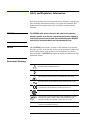
Instrument Markings
!
When you see this symbol on your instrument, you should refer to the instrument’s
instruction manual for important information.
This symbol indicates hazardous voltages.
The laser radiation symbol is marked on products that have a laser output.
This symbol indicates that the instrument requires alternating current (ac) input.
The CE mark is a registered trademark of the European Community. If it is
accompanied by a year, it indicates the year the design was proven.
The CSA mark is a registered trademark of the Canadian Standards Association.
The C-tick mark is a registered trademark of the Spectrum Management Agency
of Australia. This signifies compliance with the Australian EMC Framework
regulations under the terms of the Radio communications Act of 1992.
1SM1-A
This text indicates that the instrument is an Industrial Scientific and Medical Group
1 Class A product (CISPER 11, Clause 4).
vi Agilent 87130A Operating and Service Manual
Safety Earth
Ground
This is a Safety Class I product (provided with a protective earthing
terminal). An uninterruptible safety earth ground must be provided from the
main power source to the product input wiring terminals, power cord, or
supplied power cord set. Whenever it is likely that the protection has been
impaired, the product must be made inoperative and secured against any
unintended operation.
Before Applying Power
Verify that the product is configured to match the available main power
source as described in the input power configuration instructions in this
manual. If this product is to be powered by autotransformer, make sure the
common terminal is connected to the neutral (grounded) side of the ac power
supply.
COMPLIANCE WITH GERMAN NOISE REQUIREMENTS
This is to declare that this instrument is in conformance with the German
Regulation on Noise Declaration for Machines (Laermangabe nach der
Maschinenlaermrerordnung-3.GSGV Deutschland).
Acoustic Noise Emmision/Geraeuschemission
LpA <70 dB
LpA <70 dB
Operator position
am Arbeitsplatz
Normal position
normaler Betrieb
per ISO 7779
nach DIN 45635 t.19
Agilent 87130A Operating and Service Manual vii
General Safety Considerations
WARNING
•
This product has been designed and tested in accordance with IEC
Publication 1010, Safety Requirements for Electronic Measuring
Apparatus, and has been supplied in a safe condition. The instruction
documentation contains information and warnings which must be
followed by the user to ensure safe operation and to maintain the product
in a safe condition.
•
This is a Safety Class 1 Product provided with a protective earthing
ground incorporated in the power cord. The mains plug shall only be
inserted in a socket outlet provided with a protective earth contact. Any
interruption of the protective conductor inside or outside of the product is
likely to make the product dangerous. Intentional interruption is
prohibited.
•
The ON/OFF switch or the detachable power cord is the instrument
disconnecting device. It disconnects the mains circuits from the mains
supply before other parts of the instrument. Alternately, an externally
installed switch or circuit breaker, which is readily identifiable and is easily
reached by the operator, may be used as a disconnecting device.
•
This product is designed for use in Installation Category and Pollution
Degree 2 per IEC 1010 and 664 respectively.
•
Install the instrument according to the enclosure protection provided. This
instrument protects against finger access to hazardous parts within the
enclosure. The instrument does not protect against the ingress of water.
•
If this product is not used as specified, the protection provided by the
equipment could be impaired. This product must be used in a normal
condition (in which all means for protection are intact) only.
•
When installing the product in a cabinet, the convection into and out of the
product must not be restricted. The ambient temperature (outside the
cabinet) must be less than the maximum operating temperature of the
product by 4° C for every 100 watts dissipated in the cabinet. If the total
power dissipated in the cabinet is greater than 800 watts forced
convection must be used.
WARNING
viii Agilent 87130A Operating and Service Manual
Agilent 87130A Operating and Service Manual ix
Typeface Conventions
•
Used to emphasize important information:
Use this software only with the 87130A.
•
Used for the title of a publication:
Refer to the Agilent 87130A Operating and Service Manual.
•
Used to indicate a variable:
Type LOAD BIN filename.
Instrument Display
•
Used to show on-screen prompts and messages that you will see on the
display of an instrument:
The 87130A will display the message CAL1 SAVED.
[Keycap]
•
Used for labeled keys on the front panel of an instrument or on a
computer keyboard:
Press [Return].
{Softkey}
•
Used for simulated keys that appear on an instrument display:
Press {Prior Menu}.
User Entry
•
Used to indicate text that you will enter using the computer keyboard;
text shown in this typeface must be typed exactly as printed:
Type LOAD PARMFILE
•
Used for examples of programming code:
Italics
#endif // ifndef NO_CLASS
Path Name
•
Used for a subdirectory name or file path:
Edit the file usr/local/bin/sample.txt
Computer Display
•
Used to show messages, prompts, and window labels that appear on a
computer monitor:
The Edit Parameters window will appear on the screen.
•
Used for menus, lists, dialog boxes, and button boxes on a computer
monitor from which you make selections using the mouse or keyboard:
Double-click EXIT to quit the program.
x Agilent 87130A Operating and Service Manual
Contents
1.
Introducing the 87130A
Attenuator/Switch Driver
Features of the Attenuator/Switch Driver . . . . . . . . . . . . . . . . . . . . . . . . . 1-2
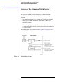
Figure 1-1. 87130A Block Diagram . . . . . . . . . . . . . . . . . . . . . . . . . 1-2
Drive Pulse and Sensing . . . . . . . . . . . . . . . . . . . . . . . . . . . . . . . . . . . 1-3
Compatible Switches and Attenuators . . . . . . . . . . . . . . . . . . . . . . . . 1-4
Table 1-1. Compatible Switches . . . . . . . . . . . . . . . . . . . . . . . . . . . . 1-4
Table 1-2. Compatible Attenuators . . . . . . . . . . . . . . . . . . . . . . . . . . 1-4
Front Panel Features . . . . . . . . . . . . . . . . . . . . . . . . . . . . . . . . . . . . . . 1-5
Figure 1-2. 87130A Front Panel Features . . . . . . . . . . . . . . . . . . . . 1-5
Unpacking Your Instrument . . . . . . . . . . . . . . . . . . . . . . . . . . . . . . . . . . . 1-6
Table 1-3. 87130A Package Contents . . . . . . . . . . . . . . . . . . . . . . . . 1-6
Determining Your Module Serial Number . . . . . . . . . . . . . . . . . . . . . 1-6
Environmental Limitations . . . . . . . . . . . . . . . . . . . . . . . . . . . . . . . . . 1-6
Figure 1-3. Packaging Materials for the 87130A Switch Driver . . . 1-7
Before Installing the Attenuator/Switch Driver . . . . . . . . . . . . . . . . . . . . 1-8
Figure 1-4. Static-Safe Work Station . . . . . . . . . . . . . . . . . . . . . . . . . 1-8
Reducing ESD Damage . . . . . . . . . . . . . . . . . . . . . . . . . . . . . . . . . . . 1-9
Table 1-4. Static-Safe ESD Accessories . . . . . . . . . . . . . . . . . . . . . . 1-9
Returning Your Instrument for Service . . . . . . . . . . . . . . . . . . . . . . . . . 1-10
2.
Installing the 87130A
Attenuator/Switch Driver
Getting Started . . . . . . . . . . . . . . . . . . . . . . . . . . . . . . . . . . . . . . . . . . . . . 2-2
Initial Inspection . . . . . . . . . . . . . . . . . . . . . . . . . . . . . . . . . . . . . . . . . 2-2
Preparing for Use . . . . . . . . . . . . . . . . . . . . . . . . . . . . . . . . . . . . . . . . 2-2
GPIB Addressing . . . . . . . . . . . . . . . . . . . . . . . . . . . . . . . . . . . . . . . . 2-3
Figure 2-1. 87130A GPIB Address Switch (Default 9 shown) . . . . . 2-3
Connecting Switch Drivers to Switches and Attenuators . . . . . . . . . . . . . 2-4
Driver Boards . . . . . . . . . . . . . . . . . . . . . . . . . . . . . . . . . . . . . . . . . . . 2-4
Using the Internal Driver . . . . . . . . . . . . . . . . . . . . . . . . . . . . . . . . . . 2-4
Figure 2-2. Typical Operating Setup Using Internal Driver . . . . . . . 2-4
Using External Drivers . . . . . . . . . . . . . . . . . . . . . . . . . . . . . . . . . . . . 2-5
Figure 2-3. Typical Operating Setup Using External Drivers . . . . . 2-5
Figure 2-4. 84940A External Driver Card with Prefixes Prior to US4016
2-6
Figure 2-5. 84940A External Driver Card with Prefixes US4016 and
Above . . . . . . . . . . . . . . . . . . . . . . . . . . . . . . . . . . . . . . . . . . . . . . 2-6
Wiring Channel Connectors . . . . . . . . . . . . . . . . . . . . . . . . . . . . . . . . 2-7
Figure 2-6. Typical Single Switch Channel Connector . . . . . . . . . . . 2-7
Connecting Multiple Driver Cards . . . . . . . . . . . . . . . . . . . . . . . . . . . 2-8
Agilent 87130A Operating and Service Manual Contents-1
Figure 2-7. Daisy Chain of Driver Cards in Single Enclosure . . . . 2-8
Figure 2-8. Daisy Chain of Driver Cards in Different Enclosures . 2-8
Connecting Attenuators . . . . . . . . . . . . . . . . . . . . . . . . . . . . . . . . . . . 2-9
Figure 2-9. Typical Attenuator Cables Connected to an 84940A . . 2-9
Optimizing Switching Speed . . . . . . . . . . . . . . . . . . . . . . . . . . . . . 2-10
Table 2-1. Relay Drive Sequence . . . . . . . . . . . . . . . . . . . . . . . . . . 2-10
Driver Card Address . . . . . . . . . . . . . . . . . . . . . . . . . . . . . . . . . . . . 2-11
Figure 2-10. Eight Driver Card Addresses . . . . . . . . . . . . . . . . . . 2-11
Driver Cable and Switch Cable Length Limitations . . . . . . . . . . . . 2-11
Pin Functions for 36-Pin I/O Data Cable . . . . . . . . . . . . . . . . . . . . 2-13
Table 2-2. Standard 36-Pin (Male) SCSI II Type Connector Pin
Functions . . . . . . . . . . . . . . . . . . . . . . . . . . . . . . . . . . . . . . . . . 2-13
Pin Functions for 68-pin Driver Output Connector . . . . . . . . . . . . 2-14
Table 2-3. Rear Panel 68-Pin (Female) SCSI II Type Connector Pin
Functions . . . . . . . . . . . . . . . . . . . . . . . . . . . . . . . . . . . . . . . . . 2-14
3.
Specifications
Performance Specifications . . . . . . . . . . . . . . . . . . . . . . . . . . . . . . . . . . . 3-2
Table 3-1. 87130A Electrical Specifications . . . . . . . . . . . . . . . . . . 3-2
Table 3-2. 87130A Environmental Specifications . . . . . . . . . . . . . . 3-3
4.
Remote Operation
Programming . . . . . . . . . . . . . . . . . . . . . . . . . . . . . . . . . . . . . . . . . . . . . . 4-2
Standard Commands . . . . . . . . . . . . . . . . . . . . . . . . . . . . . . . . . . . . . 4-2
Language . . . . . . . . . . . . . . . . . . . . . . . . . . . . . . . . . . . . . . . . . . . . . . 4-2
Programming Syntax . . . . . . . . . . . . . . . . . . . . . . . . . . . . . . . . . . . . . . . . 4-3
Talking to the Switch Driver . . . . . . . . . . . . . . . . . . . . . . . . . . . . . . . 4-3
Programming Conventions . . . . . . . . . . . . . . . . . . . . . . . . . . . . . . . . 4-3
Addressing the Switch Driver . . . . . . . . . . . . . . . . . . . . . . . . . . . . . . 4-4
Program Message Syntax . . . . . . . . . . . . . . . . . . . . . . . . . . . . . . . . . 4-4
Commands . . . . . . . . . . . . . . . . . . . . . . . . . . . . . . . . . . . . . . . . . . . . 4-5
Program Header Options . . . . . . . . . . . . . . . . . . . . . . . . . . . . . . . . . . 4-6
Program Data . . . . . . . . . . . . . . . . . . . . . . . . . . . . . . . . . . . . . . . . . . 4-6
Program Message Terminator . . . . . . . . . . . . . . . . . . . . . . . . . . . . . . 4-7
Query Command . . . . . . . . . . . . . . . . . . . . . . . . . . . . . . . . . . . . . . . . 4-7
Programming the Switch Driver . . . . . . . . . . . . . . . . . . . . . . . . . . . . . . . 4-9
Initialization . . . . . . . . . . . . . . . . . . . . . . . . . . . . . . . . . . . . . . . . . . . 4-9
Setting Up the Switch Driver . . . . . . . . . . . . . . . . . . . . . . . . . . . . . . 4-9
Receiving Information from the Switch Driver . . . . . . . . . . . . . . . . 4-9
String Variables . . . . . . . . . . . . . . . . . . . . . . . . . . . . . . . . . . . . . . . . 4-11
Instrument Status . . . . . . . . . . . . . . . . . . . . . . . . . . . . . . . . . . . . . . . 4-11
Common Commands Reference . . . . . . . . . . . . . . . . . . . . . . . . . . . . . . 4-12
Table 4-1. IEEE 488.2 Common Commands . . . . . . . . . . . . . . . . . 4-12
*CLS (Clear Status) . . . . . . . . . . . . . . . . . . . . . . . . . . . . . . . . . . . . . . . . 4-13
*ESE (Event Status Enable) . . . . . . . . . . . . . . . . . . . . . . . . . . . . . . . . . 4-14
Table 4-2. Event Status Enable Register Bit Definitions . . . . . . . . 4-14
*ESR? (Event Status Register Query) . . . . . . . . . . . . . . . . . . . . . . . . . . 4-15
Table 4-3. Event Status Register Bit Definitions . . . . . . . . . . . . . . 4-15
Contents-2 Agilent 87130A Operating and Service Manual
*IDN (Identification Number) . . . . . . . . . . . . . . . . . . . . . . . . . . . . . . . . 4-16
*OPC (Operation Complete) . . . . . . . . . . . . . . . . . . . . . . . . . . . . . . . . . 4-17
*RST (Reset) . . . . . . . . . . . . . . . . . . . . . . . . . . . . . . . . . . . . . . . . . . . . . . 4-18
*SRE (Request Enable) . . . . . . . . . . . . . . . . . . . . . . . . . . . . . . . . . . . . . 4-19
Table 4-4. Service Request Enable Register . . . . . . . . . . . . . . . . . . 4-19
*STB (Status Byte) . . . . . . . . . . . . . . . . . . . . . . . . . . . . . . . . . . . . . . . . . 4-20
Table 4-5. Status Byte Bit Definitions . . . . . . . . . . . . . . . . . . . . . . . 4-20
*TST? (Test) . . . . . . . . . . . . . . . . . . . . . . . . . . . . . . . . . . . . . . . . . . . . . . 4-21
*WAI . . . . . . . . . . . . . . . . . . . . . . . . . . . . . . . . . . . . . . . . . . . . . . . . . . . 4-22
Hierarchy . . . . . . . . . . . . . . . . . . . . . . . . . . . . . . . . . . . . . . . . . . . . . . . . 4-23
Table 4-6. Command Tree . . . . . . . . . . . . . . . . . . . . . . . . . . . . . . . . 4-23
SCPI Command Reference . . . . . . . . . . . . . . . . . . . . . . . . . . . . . . . . . . . 4-26
Channel Lists . . . . . . . . . . . . . . . . . . . . . . . . . . . . . . . . . . . . . . . . . . 4-26
SCPI Commands . . . . . . . . . . . . . . . . . . . . . . . . . . . . . . . . . . . . . . . 4-26
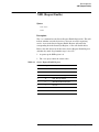
:ADD . . . . . . . . . . . . . . . . . . . . . . . . . . . . . . . . . . . . . . . . . . . . . . . . . . . . 4-27
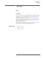
:AUTOselect . . . . . . . . . . . . . . . . . . . . . . . . . . . . . . . . . . . . . . . . . . . . . . 4-28
:CATalog? . . . . . . . . . . . . . . . . . . . . . . . . . . . . . . . . . . . . . . . . . . . . . . . . 4-29
:CLOSe . . . . . . . . . . . . . . . . . . . . . . . . . . . . . . . . . . . . . . . . . . . . . . . . . . 4-30
:CYCLes? . . . . . . . . . . . . . . . . . . . . . . . . . . . . . . . . . . . . . . . . . . . . . . . . 4-33
:DEFine . . . . . . . . . . . . . . . . . . . . . . . . . . . . . . . . . . . . . . . . . . . . . . . . . . 4-34
:DELay . . . . . . . . . . . . . . . . . . . . . . . . . . . . . . . . . . . . . . . . . . . . . . . . . . 4-36
:DELete . . . . . . . . . . . . . . . . . . . . . . . . . . . . . . . . . . . . . . . . . . . . . . . . . . 4-38
:DRIVe . . . . . . . . . . . . . . . . . . . . . . . . . . . . . . . . . . . . . . . . . . . . . . . . . . 4-40
:EERom . . . . . . . . . . . . . . . . . . . . . . . . . . . . . . . . . . . . . . . . . . . . . . . . . . 4-42
:ERRor? . . . . . . . . . . . . . . . . . . . . . . . . . . . . . . . . . . . . . . . . . . . . . . . . . 4-43
:FREE? . . . . . . . . . . . . . . . . . . . . . . . . . . . . . . . . . . . . . . . . . . . . . . . . . . 4-46
:GROUP . . . . . . . . . . . . . . . . . . . . . . . . . . . . . . . . . . . . . . . . . . . . . . . . . 4-47
:INITialize . . . . . . . . . . . . . . . . . . . . . . . . . . . . . . . . . . . . . . . . . . . . . . . . 4-48
:LABel[?] . . . . . . . . . . . . . . . . . . . . . . . . . . . . . . . . . . . . . . . . . . . . . . . . 4-49
MEMory . . . . . . . . . . . . . . . . . . . . . . . . . . . . . . . . . . . . . . . . . . . . . . . . . 4-50
:NAME . . . . . . . . . . . . . . . . . . . . . . . . . . . . . . . . . . . . . . . . . . . . . . . . . . 4-51
:OPEN . . . . . . . . . . . . . . . . . . . . . . . . . . . . . . . . . . . . . . . . . . . . . . . . . . . 4-52
:PATH . . . . . . . . . . . . . . . . . . . . . . . . . . . . . . . . . . . . . . . . . . . . . . . . . . . 4-55
:PFAil . . . . . . . . . . . . . . . . . . . . . . . . . . . . . . . . . . . . . . . . . . . . . . . . . . . 4-56
:REMove . . . . . . . . . . . . . . . . . . . . . . . . . . . . . . . . . . . . . . . . . . . . . . . . . 4-57
ROUTe . . . . . . . . . . . . . . . . . . . . . . . . . . . . . . . . . . . . . . . . . . . . . . . . . . 4-58
:SAVE . . . . . . . . . . . . . . . . . . . . . . . . . . . . . . . . . . . . . . . . . . . . . . . . . . . 4-59
STATus . . . . . . . . . . . . . . . . . . . . . . . . . . . . . . . . . . . . . . . . . . . . . . . . . . 4-60
SYSTem . . . . . . . . . . . . . . . . . . . . . . . . . . . . . . . . . . . . . . . . . . . . . . . . . 4-61
TRIGger . . . . . . . . . . . . . . . . . . . . . . . . . . . . . . . . . . . . . . . . . . . . . . . . . 4-62
:VALue . . . . . . . . . . . . . . . . . . . . . . . . . . . . . . . . . . . . . . . . . . . . . . . . . . 4-63
:VERify . . . . . . . . . . . . . . . . . . . . . . . . . . . . . . . . . . . . . . . . . . . . . . . . . . 4-64
:VERsion? . . . . . . . . . . . . . . . . . . . . . . . . . . . . . . . . . . . . . . . . . . . . . . . . 4-66
:WIDTh . . . . . . . . . . . . . . . . . . . . . . . . . . . . . . . . . . . . . . . . . . . . . . . . . . 4-67
Example Programs . . . . . . . . . . . . . . . . . . . . . . . . . . . . . . . . . . . . . . . . . 4-68
Example Speed Calculation . . . . . . . . . . . . . . . . . . . . . . . . . . . . . . . . . . 4-74
Table 4-7. Relay Drive Sequence . . . . . . . . . . . . . . . . . . . . . . . . . . . 4-74
Agilent 87130A Operating and Service Manual Contents-3
Figure 4-1. Timing Chart . . . . . . . . . . . . . . . . . . . . . . . . . . . . . . . . 4-77
5.
Replaceable Parts
Accessory Boards and Cables . . . . . . . . . . . . . . . . . . . . . . . . . . . . .
Table 5-1. Accessories . . . . . . . . . . . . . . . . . . . . . . . . . . . . . . . . . .
Firmware Revisions . . . . . . . . . . . . . . . . . . . . . . . . . . . . . . . . . . . .
Table 5-2. Replaceable Parts - 87130A Chassis Assembly (1) . . .
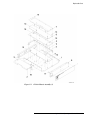
Figure 5-1. 87130A Chassis Assembly (1) . . . . . . . . . . . . . . . . . . .
Table 5-3. Replaceable Parts - 87130A Chassis Assembly (2) . . .
Figure 5-2. 87130A Chassis Assembly (2) . . . . . . . . . . . . . . . . . . .
Table 5-4. Replaceable Parts - 87130A Cable Assembly . . . . . . . .
Figure 5-3. 87130A Cable Assembly . . . . . . . . . . . . . . . . . . . . . . .
6.
5-13
5-13
5-13
5-14
5-15
5-16
5-17
5-18
5-19
Troubleshooting
Troubleshooting . . . . . . . . . . . . . . . . . . . . . . . . . . . . . . . . . . . . . . . . . . . .
Figure 6-1. 87130A DC Schematic . . . . . . . . . . . . . . . . . . . . . . . . .
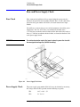
Fuse and Power Supply Check . . . . . . . . . . . . . . . . . . . . . . . . . . . . . . . .
Fuse Check . . . . . . . . . . . . . . . . . . . . . . . . . . . . . . . . . . . . . . . . . . . .
Figure 6-2. Power Supply Test Points . . . . . . . . . . . . . . . . . . . . . . .
Power Supply Check . . . . . . . . . . . . . . . . . . . . . . . . . . . . . . . . . . . . .
Procedure for Setting Up the EPROM . . . . . . . . . . . . . . . . . . . . . . . . . .
Contents-4 Agilent 87130A Operating and Service Manual
6-2
6-3
6-4
6-4
6-4
6-4
6-5
1
Introducing the 87130A
Attenuator/Switch Driver
Overview
In this chapter you will find:
•
Function, features, and capabilities of the
87130A attenuator/switch driver
•
•
•
How to unpack and check your instrument
How to set up a static-free workstation
How to contact Agilent Technologies for service
Agilent 87130A Operating and Service Manual 1-1
Introducing the 87130A Attenuator/Switch Driver
Features of the Attenuator/Switch Driver
Features of the Attenuator/Switch Driver
The Agilent 87130A attenuator/switch driver is a GPIB compatible
instrument designed to drive electromechanical switches and step
attenuators.
•
The standard instrument has a single internal driver board capable of
driving up to 31 SPDT switches, or combinations of SPDT and
multithrow switches.
•
The attenuator/switch driver may be externally connected to a maximum
of seven 84940A driver boards and can control and sense switching for
up to 248 switches.
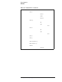
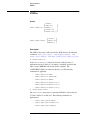
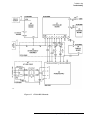
The block diagram is shown below. Refer to Figure 6-1 on page 6-3 for a
detailed DC Schematic.
Figure 1-1
87130A Block Diagram
1-2 Agilent 87130A Operating and Service Manual
Introducing the 87130A Attenuator/Switch Driver
Features of the Attenuator/Switch Driver
Drive Pulse and
Sensing
The attenuator/switch driver can deliver 500 mA, 24 Vdc current pulses to
31 individual switch sections and up to a total of 248 switch sections by the
addition of external 84940A driver boards (or driver boards inside externally
connected equipment such as switch matrixes). These low impedance pulses
can be adjusted for pulse width in order to optimize switching speed. Pulse
width and sensing delay can be set from 0.005 to 1.275 seconds.
Sensing Disabled
Each switch coil is internally connected to the + 24 V bias supply. A power
transistor on the driver board supplies the ground that will activate the switch
coil. The controller assembly actuates the transistor for a predetermined time
that is set by the :WIDTh command. (Refer to “:WIDTh” on page 4-67.) The
default setting is 30 ms.
Sensing Enabled
For switches that can be sensed, the switch coil is internally connected to the
+ 24 V bias supply via a dc switch that removes the bias from the activated
coil after the switch has changed position and applies the bias to the opposite
coil. By monitoring the presence of this bias through the opposite coil, the
switch controller can determine the switch position.
After the initial 30 ms closure pulse, an additional 20 ms time is allowed for
the sense lines to settle. At this time an error and a programmed position
check are performed.
The power supply allows the switch driver four switching operations at the
same time. This means that at the default setting, seven groups of four
switches and one group of three switches will each take 50 ms to switch and
verify. This results in a default switching speed of 0.4 seconds for 31 relays
with sensing enabled. Refer to “Example Speed Calculation” on page 4-74
for more information.
Agilent 87130A Operating and Service Manual 1-3
Introducing the 87130A Attenuator/Switch Driver
Features of the Attenuator/Switch Driver
Compatible Switches
and Attenuators
The attenuator/ switch driver is designed to drive Agilent switches and
attenuators shown in the tables below.
NOTE
If you are using switches or attenuators made by another company, check
their switching characteristic against those specified in Chapter 3,
“Specifications”.
All Agilent switches and attenuators have internal clamp diodes to limit
reverse EMF energy from the switch solenoid. If other switches are used,
this energy must be limited to less than 10 millijoules to prevent damage to
the switch driver circuit.
Table 1-1
Compatible Switches
Agilent Model Number
Description
Agilent Model Number
Description
33311A,B,C,D
Terminated SPDT
8765A,B,C,F (Opt 024)
Unterminated SPDT*
33312A,B,C
Terminated transfer
8766K
SP3T
33313A,B,C
5 port switch
8767K
SP4T
33314A,B,C,D (Opt 024)
Unterminated SPDT*
8768K
SP5T
33363K
SP3T
8769K
SP6T
33364K
SP4T
87104A,B,C
SP4T*
33365K
SP5T
87106 A,B,C
SP6T*
33366K
SP6T
87204A,B,C
SP4T
8762A,B,C,F
Terminated SPDT
87206A,B,C
SP6T
8763A,B,C,F
Terminated transfer
87222C,D,E
Transfer switch
8764A,B,C,F
5 port switch
87606B
Matrix switch
* No position verification
Table 1-2
Compatible Attenuators
Agilent Model Number
Description
Agilent Model Number
Description
33320G,H
11 dB, 1 dB steps
8494G,H
11 dB, 1 dB steps
33321G,H,K
70 dB, 10 dB steps
8495G,H,K
70 dB, 10 dB steps
33322G,H
110 dB, 10 dB steps
8496G,H
110 dB, 10 dB steps
33323K
90 dB, 10 dB steps
8497K
90 dB, 10 dB steps
33324K,L
11 dB, 1 dB steps
84904K,L
11 dB, 1 dB steps
33326K,L
90 dB, 10 dB steps
84906K,L
90 dB, 10 dB steps
33327K,L
70 dB, 10 dB steps
84907K,L
70 dB, 10 dB steps
1-4 Agilent 87130A Operating and Service Manual
Introducing the 87130A Attenuator/Switch Driver
Features of the Attenuator/Switch Driver
Front Panel Features
The front panel LEDs indicate the status of the 87130A attenuator/switch
driver. The front-panel LEDs should turn on and off while the switch driver
is performing the self-test (for example, at turn-on).
If the ERROR LED lights at any time other than during self test, an error
condition exists in the switch matrix. The switch driver ERROR light
indicates it is ready to report one or more error codes. The error codes may
be viewed by using the :ERRor? command from a controller. Refer to the
GPIB command “:ERRor?” on page 4-43 for more information.
Figure 1-2
87130A Front Panel Features
The user may remotely set the SRQ (service request) state to take place
under certain conditions, (for example: completion of an operation or if an
error condition occurs). The SRQ LED will only be lit during self test, when
it is turned on and off to test the LED.
The other LEDs, RMT (remote), LSN (listen), TLK (talk), and
SWITCHING indicate the normal functioning of the switch driver and do
not indicate an error condition.
Agilent 87130A Operating and Service Manual 1-5
Introducing the 87130A Attenuator/Switch Driver
Unpacking Your Instrument
Unpacking Your Instrument
Unpack and inspect the shipping container and its contents thoroughly to
ensure that nothing was damaged during shipment. If the shipping container
or cushioning material is damaged, the contents should be checked both
mechanically and electrically.
WARNING
To avoid hazardous electrical shock, do not perform electrical tests when there
are signs of shipping damage to any portion of the outer enclosure (covers,
panels, connectors.)
Table 1-3
87130A Package Contents
Description
Quantity
Part Number
Switch driver
1
87130A
Operating and Service Manual
1
87130-90007
Cable, 68-pin to 68-pin SCSI II, 6 ft.
1
70611-60004
❍
If the shipping container is damaged, or the cushioning material
shows signs of stress, notify the carrier as well as Agilent
Technologies. Keep the shipping material for the carrier’s
inspection. Refer to Figure 1-3.
❍
If the contents are damaged or defective, contact your nearest
Service Center listed under “Service and Support” on page v.
Agilent will arrange for repair or replacement of the damaged or
defective equipment. Always refer to your instrument by its full
model number and serial number.
Determining Your
Module Serial Number
A serial number is attached to a label on the rear panel of the module. The
first six entries are the same for all identical modules; they only change
when a change in the electrical or physical functionality is made. The
remaining entries change sequentially and are different for each module.
Environmental
Limitations
The instrument should be stored in a clean, dry environment. The following
environmental limitations apply to both shipment and storage:
to + 70° C
Temperature
− 40
Humidity
< 95% relative
Altitude
< 15300 meters (50,000 feet)
1-6 Agilent 87130A Operating and Service Manual
Introducing the 87130A Attenuator/Switch Driver
Unpacking Your Instrument
Figure 1-3
Packaging Materials for the 87130A Switch Driver
Item
Quantity
Part Number
1
1
9211-6365
Outer carton
2
1
5181-5515
Foam Insert
3
4
Description
Foam insert (Part of item 2.)
1
5181-5535
Spacer
Agilent 87130A Operating and Service Manual 1-7
Introducing the 87130A Attenuator/Switch Driver
Before Installing the Attenuator/Switch Driver
Before Installing the Attenuator/Switch Driver
Electrostatic discharge (ESD) can damage or destroy electronic components.
All work performed on assemblies consisting of electronic components
should be done at a static-safe workstation.
An example of a static-safe work station is shown below using two types of
ESD protection:
•
•
conductive table mat and wrist strap combination, and
conductive floor mat and heel strap combination
These methods may be used together or separately. A list of static-safe
accessories and their part numbers is given on the following page.
Figure 1-4
Static-Safe Work Station
1-8 Agilent 87130A Operating and Service Manual
Introducing the 87130A Attenuator/Switch Driver
Before Installing the Attenuator/Switch Driver
Reducing ESD
Damage
To help reduce the amount of ESD damage that occurs during installation,
testing, or servicing instruments use the following guidelines:
Table 1-4
•
Be sure that all instruments are properly earth-grounded to prevent
buildup of static charge.
•
Personnel should be grounded with a resistor-isolated wrist strap before
touching the center pin of any connector and before removing any
assembly from the instrument.
•
Before connecting any coaxial cable to an instrument connector for the
first time each day, momentarily ground the center and outer conductors
of the cable.
•
Handle all PC board assemblies and electronic components only at
static-safe work stations.
•
Store or transport PC board assemblies and electronic components in
static-shielding containers.
•
PC board assembly edge-connector contacts may be cleaned by using a
lintfree cloth with a solution of 80% electronics-grade isopropyl alcohol
and 20% deionized water. This procedure should be performed at a
static-safe work station.
Static-Safe ESD Accessories
Part Number
Description
9300-0797
Set includes:
3M static control mat 0.6 m x 1.2 m (2 ft x 4 ft) and 4.6 m (15 ft)
ground wire. (The wrist-strap and wrist-strap cord are not included.
They must be ordered separately.)
9300-0865
Ground wire, 4.6 m (15 ft)
9300-0980
Wrist-strap cord 1.5 m (5 ft)
9300-1367
Wrist-strap, color black, stainless steel, without cord, has four
adjustable links and a 7 mm post-type connection.
9300-1308
ESD heel-strap (reusable 6 to 12 months)
Order the above by calling an Agilent Sales and Service Office.
Agilent 87130A Operating and Service Manual 1-9
Introducing the 87130A Attenuator/Switch Driver
Returning Your Instrument for Service
Returning Your Instrument for Service
To obtain servicing information or to order replacement parts, contact your
nearest Agilent Technologies Service Center listed under “Service and
Support” on page v.
Use the following procedure to return your instrument to Agilent for service:
1. Fill out a service tag and attach it to the instrument. Please be as specific
as possible about the nature of the problem.
CAUTION
Damage can result if the original packaging materials are not used.
Packaging materials should be anti-static and should cushion the instrument
on all sides.
Never use styrene pellets in any shape as packaging materials. They do not
adequately cushion the instrument or prevent it from moving in the shipping
container. Styrene pellets can also cause equipment damage by generating
static electricity or by lodging in fan motors.
2. Place the switch driver in its original packaging materials.
If the original packaging materials are not available, you can contact an
Agilent sales and service office to obtain information on packaging
materials or you may use an alternative packing material referred to as
“bubble-pack”.
Surround the module with at least 3 to 4 inches of its original packing
material or bubble-pack to prevent it from moving in its shipping
container.
3. Place the switch driver after wrapping it with packing material, in its
original shipping container or a strong shipping container that is made of
double-walled corrugated cardboard with 159 kg (350 lb) bursting
strength.
The shipping container must be both large enough and strong enough to
accommodate your module and allow at least 3 to 4 inches on all sides
for packing material.
4. Seal the shipping container securely with strong nylon adhesive tape.
5. Mark the shipping container “Fragile, Handle with Care” to help ensure
careful handling.
6. Retain copies of all shipping papers.
1-10 Agilent 87130A Operating and Service Manual
Installing the 87130A Attenuator/Switch Driver
2
Installing the 87130A
Attenuator/Switch Driver
Overview
In this chapter you will learn about:
•
•
•
•
How to install your switch driver
How to verify its basic functionality
How to address your instrument
How to connect it to a switch matrix
Agilent 87130A Operating and Service Manual 2-1
Installing the 87130A Attenuator/Switch Driver
Getting Started
Getting Started
Initial Inspection
Preparing for Use
1. Unpack and inspect the shipping container and its contents thoroughly to
ensure that nothing was damaged during shipment. If the shipping
container or cushioning material is damaged, the contents should be
checked both mechanically and electrically. A procedure for checking
the electrical performance is given in Chapter 4, Verification.
❍
If the shipping container is damaged, or the cushioning material
shows signs of stress, notify the carrier as well as Agilent
Technologies. Keep the shipping material for the carrier’s
inspection. Refer to Figure 1-3.
❍
If the contents are damaged or defective, contact your nearest
Service Center listed under “Service and Support” on page v.
Agilent will arrange for repair or replacement of the damaged or
defective equipment.
2. Use the following properties of the attenuator/switch driver to plan your
system configuration.
Power requirements
The internal power supply adjusts automatically to the input line voltage.
See table 3-2 on page 3-3 for additional information.
Power cord
In accordance with international safety standards, a three-wire power cable
is provided with this instrument. When it is connected to an appropriate ac
power receptacle, this cable grounds the instrument cabinet. The type of
power cable plug shipped with each instrument depends on the country of
destination.
Fuses
The 87130A is shipped with a 3A fuse (F3) installed in the + 24 Vdc line and
a 3A fuse (F2) in the + 5 Vdc line. The 1 A, 250 V power line fuse is located
inside the AC input module.
2-2 Agilent 87130A Operating and Service Manual
Installing the 87130A Attenuator/Switch Driver
Getting Started
GPIB Addressing
Figure 2-1
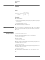
3. Use the five-bit binary address switches located on the rear panel of the
instrument to change the GPIB address.
❍
The 87130A has a factory preset address of 9. There are 32 possible
addresses. The switch labeled with a one is the least significant bit.
❍
Addresses 0 and 31 are typically reserved for GPIB functions and
should not be used. IEEE-488.1 limits the number of addressable
elements (instruments) to 16.
87130A GPIB Address Switch (Default 9 shown)
Agilent 87130A Operating and Service Manual 2-3
Installing the 87130A Attenuator/Switch Driver
Connecting Switch Drivers to Switches and Attenuators
Connecting Switch Drivers to Switches and
Attenuators
Driver Boards
The standard 87130A attenuator/switch driver has a single internal driver
board capable of driving 31 switches. The attenuator/switch driver may also
be connected to a maximum of seven external 84940A driver board which
can control and sense switching states for up to 217 additional switches.
The internal driver card is terminated with a 68-pin SCSI II type connector
for connecting external switches. The 84941A distribution board should be
used to connect the switch driver to switches and attenuators.
❍
❍
Using the Internal
Driver
Figure 2-2
The distribution board has 31 4-pin black output connectors
numbered J1 to J31 (silkscreened on the circuit side of the PCA), in
addition to 31 mating cables which allow a cable harness to be
quickly assembled to connect to relays. Refer to Figure 2-6 for pin
wiring that determines an OPEN or CLOSE condition on each
switch.
Each relay (switch) is referred to as a channel by the switch driver.
Each channel has its own unique address. The switch driver begins
numbering channels at 0 instead of 1. Switch one, wired to J1 on
driver card 1, would have a channel address of 100.
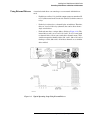
1. Connect the internal driver board of the switch driver which is
terminated with a 68-pin SCSI II type connector (driver output) to an
84941A distribution board. Use the six foot cable with two male 68-pin
SCSI II type connectors that is shipped with the 87130A.
Typical Operating Setup Using Internal Driver
2-4 Agilent 87130A Operating and Service Manual
Installing the 87130A Attenuator/Switch Driver
Connecting Switch Drivers to Switches and Attenuators
Using External Drivers
Figure 2-3
A standard switch driver can control up to seven external 84940A driver
cards.
❍
Each driver card has 31 4-pin black output connectors numbered J1
to J31 (silkscreened on the circuit side of the PCA) which connect to
relays.
❍
Each relay is referred to as a channel by the switch driver. Therefore,
there are a total of 248 relays (channels) that can be driven from a
single switch driver.
❍
Each card must have a unique address. (Refer to Figure 2-10). The
internal driver card is set to card 1. On card 1, J1 to J31 correspond
to channels 100 to 130 on your switch driver channel menu. Card 2
would correspond to channels 200 to 230; card 3, 300 to 330, and so
forth up to card 8, 800 to 830. All of these channels are set with the
drive enabled.
Typical Operating Setup Using External Drivers
Agilent 87130A Operating and Service Manual 2-5
Installing the 87130A Attenuator/Switch Driver
Connecting Switch Drivers to Switches and Attenuators
Do not connect or disconnect relays from 84940A external driver cards with
prefixes prior to US4016 while the attenuator/switch driver line switch is
turned on. An unintentional short between the + 24 V wire and the driver
outputs may result in a catastrophic driver board failure.
CAUTION
Although these driver cards will function properly when driven by the
87130A, they are only specified to 800 mA maximum per group of four
relays (200 mA per relay section); however, the + 24 V power supply from
the 87130A provides 3 A of dc current.
Break-Off Section
Figure 2-4
84940A External Driver Card with Prefixes Prior to US4016
Figure 2-5
84940A External Driver Card with Prefixes US4016 and Above
The 84940A driver board includes the following items:
Description
Quantity
Part Number
Driver board
1
84940A
Cable, 36-pin to 36-pin SCSI, female to female, 5 feet, 28 AWG
1
70611-60010
Cable, 34-pin to 36-pin SCSI, 18 inches, 28 AWG
1
70611-60011
Ribbon cable kit, 36-pin to 34-pin, 6 feet, 28 AWG
1
70611-60013
2-6 Agilent 87130A Operating and Service Manual
Installing the 87130A Attenuator/Switch Driver
Connecting Switch Drivers to Switches and Attenuators
Wiring Channel
Connectors
Figure 2-6
When installing the switch driver, it is imperative to know which wires will
cause an OPEN or CLOSE condition on each switch.
•
An OPEN condition is defined as the black wire from J1 pin 1 is
active-to-common (+ 24 Vdc red wire).
•
A CLOSE condition is defined as the white wire from J1 pin 3 is
active-to-common (+ 24 Vdc red wire).
Typical Single Switch Channel Connector
Agilent 87130A Operating and Service Manual 2-7
Installing the 87130A Attenuator/Switch Driver
Connecting Switch Drivers to Switches and Attenuators
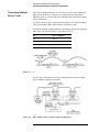
Connecting Multiple
Driver Cards
The cards are numbered from 1 to 8; the relays on each card are numbered
from 0 to 30. Each relay is referred to as a channel by the switch driver.
Therefore, there are a total of 248 relays (channels) that can be driven from a
single switch driver.
In a single enclosure, place connectors (part number 1251-7090) on ribbon
cables (part number 70611-60013) to daisy chain driver cards.
To reliably install the 34-pin connector to the ribbon cable use the following
3M tools. (To order from 3M, call 1-800-225-5373).
Figure 2-7
Item
3M Part Number
Platen
3442-1A
Locator plate
3443-94
Hand press
3540
Daisy Chain of Driver Cards in Single Enclosure
Use the cables shown below to connect 84940A external cards to expand
drive capability in different enclosures.
Figure 2-8
Daisy Chain of Driver Cards in Different Enclosures
2-8 Agilent 87130A Operating and Service Manual
Installing the 87130A Attenuator/Switch Driver
Connecting Switch Drivers to Switches and Attenuators
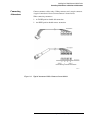
Connecting
Attenuators
Connect attenuator cables using a Viking connector and a ten pin connector.
A typical connection of four section attenuators is shown below.
When connecting attenuators
•
•
Figure 2-9
A CLOSE position should add attenuation.
An OPEN position should remove attenuation.
Typical Attenuator Cables Connected to an 84940A
Agilent 87130A Operating and Service Manual 2-9
Installing the 87130A Attenuator/Switch Driver
Connecting Switch Drivers to Switches and Attenuators
Optimizing Switching
Speed
To increase the speed at which your switch matrix operates, refer to the table
below to determine which four relays, when connected, will be on the same
drive lines.
a. Refer to Figure 2-6 to wire your relays into the arbitrary positions of
OPEN and CLOSE.
b. Refer to the section “Example Speed Calculation” on page 4-74 for
an explanation on calculating and minimizing overall switching
time.
Switching speed is a function of pulse widths, sensing delays, the state of the
chosen channels, the sequence of relays driven and the power supply
recovery time. Pulse widths, sensing delays, and which channels are opened
or closed are determined by the user, and cannot be predicted here.
NOTE
The channel number must be preceded by the driver card number. Channels
connected to driver card 1 would be numbered 100 to 130; card 2, 200 to
230; card 3, 300 to 330, and so forth up to card 800 to 830. All of these
channels are set with the drive enabled.
.
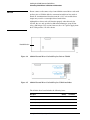
Table 2-1
NOTE
Relay Drive Sequence
Drive Line
Connector Locator
Channel List
1
J1, J2, J3, J4
00, 01, 02, 03
2
J5, J6, J7, J8
04, 05, 06, 07
3
J9, J10, J11, J12
08, 09, 10, 11
4
J13, J14, J15, J16
12, 13, 14, 15
5
J17, J18, J19, J20
16, 17, 18, 19
6
J21, J22, J23, J24
20, 21, 22, 23
7
J25, J26, J27, J28
24, 25, 26, 27
8
J29, J30, J31
28, 29, 30
The maxium Power Supply Recovery Time should only be required when
driving multiple external driver boards with longer interconnect cables. A
significant switching speed advantage can be realized if this value is reduced
from the 200 msec default. See the command called “TRIGger” on
page 4-62 and the “Example Speed Calculation” on page 4-74.
2-10 Agilent 87130A Operating and Service Manual
Installing the 87130A Attenuator/Switch Driver
Connecting Switch Drivers to Switches and Attenuators
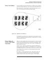
Driver Card Address
Set the 4-bit DIP switch on the 84940A driver assembly card to each address
as shown in the figure below. (S1 “up” is open or away from the PC board.)
Each card must have a unique address setting. The internal driver is set to
card 1. Card 1 shown below is the factory default setting.
Figure 2-10
Eight Driver Card Addresses
It is impossible to predict the exact configuration of your particular switch
matrix. It is assumed that each 84940A driver assembly will be in a separate
grounded switch matrix box.
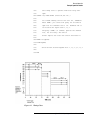
Driver Cable and
Switch Cable Length
Limitations
When you connect multiple driver boards and switches at a distance from the
87130A, voltage drop limitations due to switch drive requirements, switch
quiescent current, drive transistor drop, cable resistance, and LED current
must be taken into account.
Agilent “24 volt” switches are guaranteed to work with a minimum drive
voltage of 20 volts. The 87130A puts out a minimum of 22.5 V, and the open
drain DMOS output drivers of each channel on the driver board have a drop
of 1.0 V. Thus 1.5 V is left for the total voltage drop for the driver board
cables and switch wires.
For example, a seventh external driver board, “fully loaded” with seven
87104A switches (maximum 350 mA quiescent current plus 400 mA
actuating current) located at the end of the sequence of 70611-60010,
Agilent 87130A Operating and Service Manual 2-11
Installing the 87130A Attenuator/Switch Driver
Connecting Switch Drivers to Switches and Attenuators
70611-60011, and 70612-60011 cables of #28 AWG wire size, at a total
cable length of 32.8 feet from the 87130A would have a voltage of 20.3 volts
available at the driver board. (21.5 V - (750 mA X 0.065 ohms per foot X
32.8 feet X 0.75)).*
This leaves 0.3 V that can be dropped in the wires from the board to the
switches. Thus, if each switch has 400 mA actuating plus 50 mA quiescent
current, a combined length of 16.6 feet of #26 AWG wire would be the
maximum length permissible to meet switch specifications. (450 mA X 0.04
ohms per foot X 16.6 feet = 0.3 V) Any LED current must also be added to
these calculations.
Special longer lengths of heavier-gauge driver (68 pin) and CPU (36 pin)
cables are available. Refer to “Service and Support” on page v for ordering
information.
* This calculation makes two assumptions:
(1) There are no other devices which consume quiescent current
connected to the driver boards between the 87130A and the
seventh driver board.
(2) The factor 0.75 in this equation is used to calculate an “equivalent”
cable length for forward and return path since there are two + 24 V
lines in parallel and 4 return lines in parallel.
2-12 Agilent 87130A Operating and Service Manual
Installing the 87130A Attenuator/Switch Driver
Connecting Switch Drivers to Switches and Attenuators
Pin Functions for
36-Pin I/O Data Cable
Table 2-2
•
The standard switch driver has a high density male, 36-pin SCSI II type
connector.
•
The standard I/O data cable is a five-foot 28 AWG cable with two
female, 36-pin SCSI II type connectors.
Standard 36-Pin (Male) SCSI II Type Connector Pin Functions
Pin
Function
Pin
Function
1
Return
19
D6, Data Line
2
Return
20
D7, Data Line
3
NC
21
D8, Data Line
4
NC
22
D9, Data Line
5
NC
23
D10, Data Line
6
NC
24
D11, Data Line
7
+ 5 Vdc
25
D12, Data Line
8
+ 5 Vdc
26
D13, Data Line
9
+ 24 Vdc
27
D14, Data Line
10
+ 24 Vdc
28
NC
11
Return
29
NC
12
Return
30
Register CLR
13
D0,Data Line
31
Store
14
D1,Data Line
32
I/O
15
D2,Data Line
33
Return
16
D3,Data Line
34
Return
17
D4,Data Line
35
NC
18
D5,Data Line
36
NC
Agilent 87130A Operating and Service Manual 2-13
Installing the 87130A Attenuator/Switch Driver
Connecting Switch Drivers to Switches and Attenuators
Pin Functions for
68-pin Driver Output
Connector
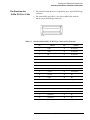
Table 2-3
•
The 87130A has a rear-panel 68-pin connector for driving attached
switches. The standard output cable is a six-foot 28 AWG cable with two
male 68-pin SCSI II type connectors.
•
When you wire the switch driver to the switches, use the following table
to define an OPEN or CLOSE position.
Rear Panel 68-Pin (Female) SCSI II Type Connector Pin Functions
Pin
1
2
3
4
5
6
7
8
9
10
11
12
13
14
15
16
17
18
19
20
21
22
23
24
25
26
27
28
29
30
31
32
33
34
Function
Return
Channel 0, Open
Channel 1, Open
Channel 2, Open
Channel 3, Open
Channel 4, Open
Channel 5, Open
Channel 6, Open
Channel 7, Open
Channel 8, Open
Channel 9 Open
Channel 10, Open
Channel 11, Open
Channel 12, Open
Channel 13, Open
Channel 14, Open
Channel 15 Open
Channel 16, Open
Channel 17, Open
Channel 18, Open
Channel 19, Open
Channel 20, Open
Channel 21, Open
Channel 22, Open
Channel 23, Open
Channel 24, Open
Channel 25, Open
Channel 26, Open
Channel 27, Open
Channel 28, Open
Channel 29, Open
Channel 30, Open
+ 24 Vdc
Return
Pin
35
36
37
38
39
40
41
42
43
44
45
46
47
48
49
50
51
52
53
54
55
56
57
58
59
60
61
62
63
64
65
66
67
68
2-14 Agilent 87130A Operating and Service Manual
Function
Return
Channel 0, Close
Channel 1, Close
Channel 2, Close
Channel 3, Close
Channel 4, Close
Channel 5, Close
Channel 6, Close
Channel 7, Close
Channel 8, Close
Channel 9, Close
Channel 10, Close
Channel 11, Close
Channel 12, Close
Channel 13, Close
Channel 14, Close
Channel 15, Close
Channel 16, Close
Channel 17,Close
Channel 18, Close
Channel 19, Close
Channel 20, Close
Channel 21, Close
Channel 22, Close
Channel 23, Close
Channel 24, Close
Channel 25, Close
Channel 26, Close
Channel 27, Close
Channel 28, Close
Channel 29, Close
Channel 30, Close
+ 24 Vdc
Return
3
Specifications
Overview
Performance specifications are the performance standards or limits against
which the 87130A can be tested. The specifications are organized into two
categories:
•
Measurement related specifications which describe warranted
performance for the 87130A over the temperature range of 0 to + 55 °C
after one hour of continuous operation, unless otherwise noted.
•
Characteristics which provide useful (typical) but non-warranted
functional and performance information for the 87130A.
Agilent 87130A Operating and Service Manual 3-1
Specifications
Performance Specifications
Performance Specifications
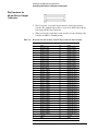
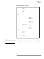
Table 3-1
87130A Electrical Specifications
Electrical Specifications
Drive Capacity - 87130A
248 relays, when mated with seven external 84940A daisy chained driver cards.
Each 84940A can drive up to 31 relays. The equivalent of one 84940A
driver card is installed within the 87130A.
Voltage
+ 24 + 3.0 / − 1.5 Vdc
Current Pulses
1600 mA maximum per four relay group
400 mA per relay (typically 500 mA maximum)
Pulse width is adjustable for 5 ms to 1275 ms ± 5 ms, in 5 ms steps.
Load Inductance1
Typically < 500 mH
Load Capacitance
Typically < 0.01 µF
Switching Speed
Sensing delay is adjustable, per relay, from 5 to 1275 ms ± 5 ms. Pulse width is also
adjustable, per relay, from 5 to 1275 ± 5 ms. Power Supply RecoveryTime is adjustable
from 0 to 200 msec
Refer to Chapter 6, “Troubleshooting.” The final switching speed is a function of
pulse widths, sensing delays, the sequence of relays driven, the state of the chosen
channels, and the Power Supply Recovery Time.
Remote Programming
All functions are GPIB programmable except the line switch and bus address.
All functions are programmable to conform with IEEE 488.2-1987 Standard Commands
for Programmable Instruments (SCPI).
The 87130A can output over the interface almost all settings, error/malfunction codes
and operational status codes.
Interface to Controller
GPIB
Interface to External Driver Cards
36-pin SCSI II type
Interface to Relays
68-pin SCSI II type
Hardware Limits
Each open collector driver IC can drive only one channel (a maximum of four switches) at
a time to avoid exceeding package dissipation limits.
1. Refer to “Compatible Switches and Attenuators” on page 1-4 if you are using switches or
attenuators made by another company.
3-2 Agilent 87130A Operating and Service Manual
Specifications
Performance Specifications
Table 3-2
87130A Environmental Specifications
Environmental Specifications
Temperature
Operating
0 to + 55 °C
Non-operating
− 40 to 70 °C
Humidity
Operating and
Non-operating
80% relative humidity up to 31 °C decreasing linearly to 50% relative humidity at 40 °C
Altitude
Operating and non-operating
Environmental Compatibility
5600 meters (15,000 feet)
Radiated and conducted emission is in compliance with CISPR Pub 11/1990, Group 1, Level A
Environmental Qualification Test
Humidity
5 day, 25 to 40 °C, 50 to 95% relative humidity
Vibration
a. Operating: MIL-PRF-28800F, Class 3, par. 4.5.5.3.1 (random, 10 to 500 Hz, 0.21 g rms)
b. Non-operating: swept sine, 5 to 500 Hz, 0.5g, 15 min/axis, 3 axis
c. Non-operating: MIL-PRF-28800F, Class 3, par. 4.5.5.3.1 (random, 10 to 500 Hz, 2.1 g rms)
Shock
a. Non-operating, 170 g, 1/2 sine 2ms, 1 drop/face, 6 faces
b. Non-operating, 30 g, trapezoidal, 28 ms, 1 drop/face, 6 faces
Environmental Conditions
This product is designed for indoor use in Installation Category II and Pollution Degree 2 per
IEC 1010 and IEC 664, respectively. Enclosure protection is IP 2 0 according to IEC 529.
Line Voltage
100 to 240 Vac
Power Consumption
110 Watts MAX
Weight
6.2 kg (13.7 lb)
Dimensions
10.2 cm (h) x 45.7 cm (w) X 55.9 cm (d)
4 in. x 18 in. x 22.5 in
Agilent 87130A Operating and Service Manual 3-3
Specifications
Performance Specifications
3-4 Agilent 87130A Operating and Service Manual
4
Remote Operation
Overview
In this chapter you will learn about programming the 87130A using a
controller:
•
How to set up the switch driver and start programming groups and paths
for switches
•
•
•
•
How to set switch delay, pulse width, and sensing
How to sense switch status
How to store and retrieve switch parameters via remote interface
How to perform more complicated tasks using a combination of these
four basic functions
You will also find:
•
•
•
•
A command tree of SCPI commands
An alphabetical list of common commands
An alphabetical list of SCPI commands
Three programming examples:
❍
Save memory
❍
Restore memory
❍
Speed calculation
Agilent 87130A Operating and Service Manual 4-1
Remote Operation
Programming
Programming
Standard Commands
The instrument command language is Standard Commands for
Programmable Instruments (SCPI).
The programming examples and information in this chapter use the SCPI
format. SCPI follows IEEE 488.2-1987 Codes, Formats, Protocols and
Common Commands. Commands are sent over an GPIB bus which follows
IEEE 488.1.
If you are already familiar with Standard Commands for Programmable
Instruments (SCPI) programming techniques, go to the section “Example
Speed Calculation” on page 4-74 for switching speed information. The
alphabetical listing of commands and command tree can be used for your
own applications.
Language
The programming examples in this manual are written in HP BASIC 5.0 for
GPIB.
HP BASIC handles some of the redundant miscellaneous overhead
associated with IEEE Standard 488.1 (GPIB). For instance, when a BASIC
OUTPUT statement is used (by the active controller) to send data to an
GPIB device, a sequence of commands and data are sent over the bus. The
HP BASIC OUTPUT statement causes more than just the output of data to
take place.
OUTPUT 709 “Data”
1. The unlisten command is sent.
2. The talker’s address command is sent (the address of the computer).
3. The listener’s address command (09) is sent.
4. The data bytes “D”, “a”, “t”, and “a” are sent.
5. Terminators CR and LF are sent.
All bytes are sent using the GPIB’s interlocking handshake to ensure that the
listener has received each byte.
For controllers that are using a programming language other than
HP BASIC, additional steps may have to be added to the program examples
given in this manual. For more information, refer to IEEE Standard 488.1
(GPIB) and IEEE Standard 488.2-1987 Codes, Formats, Protocols and
Common Commands.
4-2 Agilent 87130A Operating and Service Manual
Remote Operation
Programming Syntax
Programming Syntax
Talking to the Switch
Driver
In general, computers acting as controllers communicate with the switch
driver by passing messages over a remote interface using the I/O statements
provided in the instruction set of the controller’s host language. Therefore,
the messages for programming the switch driver described in this manual,
will normally appear as ASCII character strings imbedded inside the I/O
statements of your controller’s program.
For example, the HP 9000 Series 300 BASIC and PASCAL language
systems use the OUTPUT statement for sending program messages to the
switch driver, and the ENTER statement for receiving response messages from
the switch driver.
Messages are placed on the bus by using an output command and passing the
device selector, program message, and terminator. Passing the device
selector ensures that the program message is sent to the correct interface and
instrument.
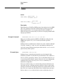
Example
The following query command reads out the firmware datecode:
OUTPUT <device selector>;“:SYSTEM:VERSION?”
where <device selector> represents the address of the device being
programmed.
Programming
Conventions
The programming examples in this manual are written in HP Basic 5.0 for an
GPIB controller compatible system.
•
The actual OUTPUT command used when programming is dependent on
the controller and the programming language being used.
•
Angular brackets “< >,” in this manual, enclose words or characters that
symbolize a program code parameter or a bus command.
•
Information that is displayed in quotes represents the actual message
that is sent across the bus. The message terminator (NL or EOI) is the
only additional information that is also sent across the bus.
•
On most controllers, it is not necessary to type in the actual
<terminator> at the end of the program message. These controllers
automatically supply the program message terminator when the return
key is pressed.
Agilent 87130A Operating and Service Manual 4-3
Remote Operation
Programming Syntax
Addressing the Switch
Driver
Since GPIB can address multiple devices through the same interface card,
the device selector passed with the program message must include not only
the correct interface code, but also the correct instrument address.
Interface Select Code (Selects Interface)
Each interface card has a unique interface select code. This code is used by
the controller to direct commands and communications to the proper
interface. The default is typically 7 for GPIB controllers.
Instrument Address (Selects Instrument)
Each instrument on an GPIB bus must have a unique instrument address
between decimal 0 and 30. The address must not be the address of the
controller. (Refer to Chapter 2, “Installing the 87130A Attenuator/Switch
Driver.”) The device address passed with the program message must include
both the correct instrument address and the correct interface select code.
Example
DEVICE SELECTOR = (Interface Select Code x 100) + (Instrument Address)
If the instrument address for the switch driver is 9 and the interface select
code is 7, when the program message is passed, the routine performs its
function on the instrument at device selector 709.
For the switch driver, the instrument address is typically set to 9 at the
factory. The program examples in this manual assume the switch driver is set
to device address 709.
Program Message
Syntax
To program the switch driver over the bus, you must have an understanding
of the command format and structure expected by the switch driver.
The switch driver is remotely programmed with program messages. These
are composed of sequences of program message units, with each unit
representing a program command or query.
A program command or query is composed of a sequence of functional
elements that include separators (a blank space which is required to separate
the program mnemonic from the program data), headers, program data, and
terminators. These elements are sent to the switch driver over the system
interface as a sequence of ASCII data messages.
4-4 Agilent 87130A Operating and Service Manual
Remote Operation
Programming Syntax
Commands
A command is composed of a header, any associated data, and a terminator.
The header is the mnemonic or mnemonics that represent the operation to be
performed by the switch driver. The different types of headers are discussed
in the following paragraphs.
Compound Command Header
Compound command headers are a combination of two or more program
mnemonics. The first mnemonic selects the subsystem, and the last
mnemonic selects the function within that subsystem. Additional
mnemonics appear between the subsystem mnemonic and the function
mnemonic when there are additional levels within the subsystem that must
be transversed. The mnemonics within the compound message are separated
by colons.
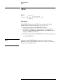
Example
To execute a single function within a subsystem:
:<subsystem>:<function><separator><program data><terminator>
ROUTE:GROUP <group name>:AUTOSELECT:OFF;
Example
To transverse down a level of a subsystem to execute a subsystem within that
subsystem:
:<subsystem>:<subsystem>:<function><separator><program data>
<terminator>
ROUTE:GROUP:LABEL “Atten 0 to 110 dB by 10 dB steps”;
Selecting Multiple Subsystems
You can send multiple program commands and program queries for different
switch driver subsystems on the same line by separating each command with
a semicolon.
Example
The colon following the semicolon enables you to enter a new subsystem.
:<subsystem>:<function><separator><data>;
<function><separator><data><terminator>
ROUTE:DRIVE:OFF:ALL;:SYSTEM:VERSION?
Common Command Header
Common command headers control IEEE 488.2 functions within the switch
driver (such as clear status, etc.). Their syntax is:
*<command header><terminator>
No space or separator is allowed between the asterisk and the command
header.
Agilent 87130A Operating and Service Manual 4-5
Remote Operation
Programming Syntax
Example
*CLS is an
example of a common command header.
*CLS; ROUTE:DRIVE:ON (@100,102,104,106,....);
Common commands used by the switch driver are explained in more detail
in the “Common Command Reference” later in this chapter.
Program Header
Options
Program headers can be sent using any combination of uppercase or
lowercase ASCII characters.
Both program command and query headers may be sent in either longform
(complete spelling), shortform (abbreviated spelling), or any combination of
longform and shortform.
NOTE
ONLY the longform or shortform of a command will be accepted by the
switch driver. Either of the following examples read out the firmware
datecode:
SYSTEM:VERSION?
SYST:VERS?
Program Data
– longform
– shortform
❍
Programs written in longform are easy to read and are almost
self-documenting.
❍
The shortform syntax conserves the amount of controller memory
needed for program storage and reduces the amount of I/O activity.
The shortform abbreviation is given for each command in the
section “SCPI Command Reference” on page 4-26.
Program data is used to convey a variety of types of parameter information
related to the command header. At least one space must separate the
command header or query header from the program data.
<program mnemonic><separator><data><terminator>
When a program mnemonic or query has multiple data parameters, a comma
separates sequential program data.
Example
<program mnemonic><separator><data>,<data><terminator>
ROUTE:DELAY .02,(@101,103,105);
4-6 Agilent 87130A Operating and Service Manual
Remote Operation
Programming Syntax
Character Program Data
Character program data is used to convey parameter information as alpha or
alphanumeric strings.
Example
ROUTE:VERIFY:ON:ALL
The :VERIFY function is specified to be ON for ALL channels.
Numeric Program Data
Some command headers require program data to be a number.
Example
ROUTE:DELAY .03,(@101,103,105)
where the :DELAY function is specified to be 30 ms on channels 101, 103,
and 105.
Program Message
Terminator
The program codes within a data message are executed after the program
message terminator is received. The terminator may be either an NL (New
Line) character, an EOI (End-Or-Identify) asserted, or a combination of the
two. All three ways are equivalent. Asserting EOI sets the GPIB EOI control
line low on the last byte of the data message. The NL character is an ASCII
linefeed (decimal 10).
Query Command
Command headers immediately followed by a question mark (?) are queries.
Query commands are used to find out how the switch driver is currently
configured. After receiving a query, the switch driver interrogates the
requested function and places the answer in its output queue. The output
message remains in the queue until it is read or another command is issued.
When read, the message is transmitted across the bus to the designated
listener (typically a controller).
Example
The query ROUTE:PATH:VALUE? <path name> places the value of the named
path in the output queue. In conjunction with this, the controller input
statement:
ENTER <device selector>;Values$
passes the value across the bus to the controller and places it in the BASIC
variable “Values$”.
Agilent 87130A Operating and Service Manual 4-7
Remote Operation
Programming Syntax
Query commands are also used to get results of switch status made by the
switch driver, with the query actually activating the switch.
Example
ROUTe:CLOSE? <channel spec>
instructs the driver to sense the status of the switch and place the result in the
output queue.
The output queue must be read before the next program message is sent.
Example
When the query
ROUTE:VERIFY:ON?
is sent, that query must be followed with a program statement like,
ENTER 709;Verify$
to read the result of the query and place the result in a BASIC variable
(Verify$).
Sending another command before reading the result of the query will cause
the output buffer to be cleared and the current response to be lost. This will
also generate an error in the error queue.
4-8 Agilent 87130A Operating and Service Manual
Remote Operation
Programming the Switch Driver
Programming the Switch Driver
Initialization
To make sure the bus and all appropriate interfaces are in a known state,
begin every program with an initialization statement.
Example
CLEAR 709
! initializes the interface of the driver.
Then initialize the switch driver to a preset state. For example:
OUTPUT 709;“*RST”
! initializes the instrument to a preset state.
The actual commands and syntax for initializing the switch driver are
discussed in the section “Common Commands Reference” on page 4-12.
Refer to the controller manual for information on initializing the interface.
Setting Up the Switch
Driver
A typical switch driver setup would set the drive (ON or OFF) paths, delay
time, sensing (ON or OFF), and pulse width. Some typical examples of the
commands sent to the driver are:
OUTPUT 709;“*CLS;ROUTE:DRIVE:ON (@100,102,104,106,....);”
OUTPUT 709;“ROUTE:DRIVE:OFF (@101,103,105,107,....);”
OUTPUT 709;“ROUTE:VERIFY:ON (@100,102,104,106,....);”
OUTPUT 709;“ROUTE:WIDTH .04,(@100,102,104,106,....);”
OUTPUT 709;“ROUTE:DELAY .03,(@100,102,104,106,....);”
Receiving Information
from the Switch Driver
After receiving a query (command header followed by a question mark), the
switch driver interrogates the requested function and places the answer in its
output queue. The answer remains in the output queue until it is read or
another command is issued. When read, the message is transmitted across
the bus to the controller.
The input statement for receiving a response message from an instrument’s
output queue typically has two parameters; the device address and a format
specification for handling the response message.
Example
To read the result of the query command
:GROUP:LABEL?
you would execute the statement:
10
OUTPUT 709;“ROUT:GROUP:LABEL? GROUP1”
20
ENTER 709;Setting$
Agilent 87130A Operating and Service Manual 4-9
Remote Operation
Programming the Switch Driver
where GROUP1 represents the name of the desired group. This would enter the
current label of the group in the string variable Setting$.
Example
All results for queries sent in a program message must be read before
another program message is sent.
When you send the query:ROUTe:CLOSE? (@101)
you must follow that query with the program statement:
ENTER 709;Sense$
to read the result of the query and place the result in a variable (SENSE$).
NOTE
•
Sending another command before reading the result of the query will
cause the output buffer to be cleared and the current response to be lost.
This will also cause an error to be placed in the error queue.
•
Executing an ENTER statement before sending a query will cause the
controller to wait indefinitely.
•
The actual ENTER program statement used when programming is
dependent on the programming language being used.
The format specification for handling the response message is dependent
on both the controller and the programming language.
•
4-10 Agilent 87130A Operating and Service Manual
Remote Operation
Programming the Switch Driver
String Variables
Example
If you want to observe the headers for queries, you must bring the returned
data into a BASIC string variable. Reading queries into string variables is
simple and straightforward, requiring little attention to formatting.
ENTER 709;Result$
places the output of the query in the string variable Result$.
The output of the switch driver may be either numeric or character data
depending on what is queried. Refer to the specific commands for the
formats and types of data returned from queries.
For the example programs, assume that the device being programmed is at
device selector 709. The actual address will vary according to how you have
configured the bus for your own application.
Example
This example shows the data being returned to a string variable:
10 DIM Rang$[40]
20 OUTPUT 709;“ROUTE:VERIFY:OFF:ALL;”
30 OUTPUT 709;“ROUTE:VERIFY:OFF? (@101:105);”
40 ENTER 709;Rang$
50 PRINT Rang$
60 END
After running this program, the controller displays a list of 1’s or 0’s
separated by commas for every channel in the list.
1,1,1,1,0
Instrument Status
Status registers track the current status of the switch driver. By checking the
instrument status, you can find out whether an operation has been
completed, whether the switch driver is receiving triggers, and query for
command and execution errors. Refer to the command *ESR? (Event Status
Register Query) on page 4-15 for more information.
Agilent 87130A Operating and Service Manual 4-11
Remote Operation
Common Commands Reference
Common Commands Reference
The common commands used in this instrument are shown in the following
table.
Table 4-1
•
The common commands control some of the basic instrument functions,
such as instrument identification and reset and how status is read and
cleared.
•
The common commands are defined by the IEEE 488.2 standard and are
common to all instruments that comply with this standard.
IEEE 488.2 Common Commands
Command
Command Name
*CLS
Clear Status Command
*ESE
Event Status Enable Command
*ESE?
Event Status Enable Query
*ESR?
Event Status Register Query
*IDN?
Identification Query
*OPC
Operation Complete Command
*OPC?
Operation Complete Query
*RST
Reset Command
*SRE
Service Request Enable Command
*SRE?
Service Request Enable Query
*STB?
Read Status Byte Query
*TST?
Self-Test Query
*WAI
Wait-to-Continue Command
4-12 Agilent 87130A Operating and Service Manual
Remote Operation
*CLS (Clear Status)
*CLS (Clear Status)
Syntax
*CLS
Description
The *CLS (clear status) common command clears the status data structures,
including the device defined error queue. This command also clears *OPC
and *OPC?.
If the *CLS command immediately follows a PROGRAM MESSAGE
TERMINATOR, the output queue and the MAV bit will be cleared.
Example Command
OUTPUT 709;“*CLS”
Agilent 87130A Operating and Service Manual 4-13
Remote Operation
*ESE (Event Status Enable)
*ESE (Event Status Enable)
Syntax
*ESE mask
*ESE?
Description
The *ESE command sets the Standard Event Status Enable Register bits. This
register contains a mask value for the bits to be enabled in the Standard
Event Status Register. A one in the Standard Event Status Enable Register
will enable the corresponding bit in the Standard Event Status Register; a
zero will disable the bit.
Refer to the table below for the information about the Standard Event Status
Enable Register bits, bit weights, and what each bit masks. Valid number
range is 0 to 255.
The *ESE query returns the current contents of the register.
Table 4-2
Example Command
Example Query
Event Status Enable Register Bit Definitions
Bit
Weight
Enables
7
128
PON- Power ON
6
64
(not used)
5
32
CME- Command Error
4
16
EXE- Execution Error
3
8
DDE- Device Dependent Error
2
4
QYE- Query Error
1
2
(not used)
0
1
OPC- Operation Complete
OUTPUT 709;”*ESE 64”
OUTPUT 709;”*ESE?”
ENTER 709; Event
PRINT Event
4-14 Agilent 87130A Operating and Service Manual
Remote Operation
*ESR? (Event Status Register Query)
*ESR? (Event Status Register Query)
Syntax
*ESR?
Description
The *ESR query returns the contents of the Standard Event Status Register.
The table shows each bit in the Event Status Register and the bit weight.
When you read the Event Status Register, the value returned is the total bit
weights of all bits that are high at the time you read the byte. The register is
cleared to 0 on a *CLS and after *ESR? is executed.
Refer to the command *STB (Status Byte) on page 4-20 to learn how
the ESR is reported through the Status Byte.
Table 4-3
Example Query
Event Status Register Bit Definitions
Bit
Weight
Name
Condition
7
128
PON
1 = an OFF to ON transition has occurred
6
64
URQ
(not used) always 0
5
32
CME
0 = no command errors
1 = a command error has been detected
4
16
EXE
0 = no execution errors
1 = an execution error has been detected
3
8
DDE
0 = no device dependent errors
1 = a device dependent error has been detected
2
4
QYE
0 = no query errors
1 = a query error has been detected
1
2
RQC
(not used) always 0
0
1
OPC
0 = operation is not complete
1 = operation is complete
OUTPUT 709;“*ESR?”
ENTER 709; Event
PRINT Event
Agilent 87130A Operating and Service Manual 4-15
Remote Operation
*IDN (Identification Number)
*IDN (Identification Number)
Syntax
*IDN?
Description
The *IDN query allows the instrument to identify itself. It returns a string
such as:
HEWLETT-PACKARD,87130A,US12345678,950713
Where 950713 is the firmware version number and US12345678 is the serial
number.
Example Command
DIM Id$[72]
OUTPUT 709;“*IDN?”
ENTER 709;Id$
PRINT Id$
4-16 Agilent 87130A Operating and Service Manual
Remote Operation
*OPC (Operation Complete)
*OPC (Operation Complete)
Syntax
*OPC
*OPC?
Description
The *OPC and *OPC? commands are used to synchronize remote interface
software to internal module events.
•
•
•
The *OPC (operation complete) command will cause the instrument to
set the operation complete bit in the Standard Event Status Register
when any switching operations that were in process at the time the *OPC
command was received have completed.
*OPC
is also used to signal the end of MEM:SAVE operation.
*OPC? causes a 1 to be put into the output buffer when any switching
operations that were in process at the time the *OPC? command was
received have completed.
If no switching operations were in process at the time the command was
sent, the response will be generated immediately. Hence *OPC or *OPC?
should only be sent after an operation has been initiated.
Example Command
Example Query
OUTPUT 709;“*OPC”
The following sequence is correct, because the OPC command is sent after
the operation is initiated:
OUTPUT 709; “ROUT:CLOS (@1(1,3,5,7,9));*OPC?”
ENTER 709;A
PRINT A
The following sequence is incorrect, because the OPC command is sent
before the operation is initiated:
*OPC?;ROUT:CLOSE (@1(1,3,5,7,9));
Agilent 87130A Operating and Service Manual 4-17
Remote Operation
*RST (Reset)
*RST (Reset)
Syntax
*RST
Description
*RST is
equivalent to a power up condition for the switch hardware.
All relays for which DRIVE is ON are set to the positions determined by
ROUTe:PFAil. For any relays not in either the ROUTe:PFAil:OPEN or
ROUTe:PFAil:CLOSE list, the positions which are stored in the “last state”
list in RAM are used to set the initial switch position. The “last state” list
contains the programmed positions of the switch hardware that existed the
last time a MEM:SAVE command or a SAVE TO EEROM keypress took place.
The setting of the switches during *RST or power up is done with VERIFY
turned OFF, to get all the relays and sense lines into a known state. VERIFY
is then turned on for any switches in the VERIFY list.
*RST affects
only the switches themselves and does not affect the
configuration data stored in RAM (DRIVE and VERIFY lists, drive and
delay times, etc).
The [IP] or [Instr Preset] key does a *RST operation, as does the *TST?
command.
Example Command
NOTE
OUTPUT 709;“*RST”
The power supply recovery time (see TRIG:SEQ:DEL on page 4-62) will be
reset to the default value of 200 msec if the *RST command is issued.
4-18 Agilent 87130A Operating and Service Manual
Remote Operation
*SRE (Request Enable)
*SRE (Request Enable)
Syntax
*SRE mask
*SRE?
Description
The *SRE command sets the Service Request Enable Register bits. This will
indicate whether or not the device has at least one reason for requesting
service. A one in the Service Request Enable Register will enable the
corresponding bit in the Status Byte Register; a zero will disable the bit.
Refer to the table below for the bits in the Service Request Enable Register
and what they mask. Legal number range is 0 to 255.
•
•
Table 4-4
At power up the SRE register is 0.
The *SRE query returns the current value.
Service Request Enable Register
Bit
Weight
Enables
7
128
SCPI Operation Summary Bit
6
64
RQS - Request Service
5
32
ESR - Event Status Register
4
16
MAV - Message Available
3
8
SCPI Questionable Summary Bit
2
4
Not used
1
2
Not used
0
1
Not used
Agilent 87130A Operating and Service Manual 4-19
Remote Operation
*STB (Status Byte)
*STB (Status Byte)
Syntax
*STB?
Description
The *STB query returns the current value of the instrument’s status byte.
Refer to the table below for the definitions of the bits in the status byte.
Table 4-5
Example Query
Status Byte Bit Definitions
Bit
Weight
Name
Condition
7
128
OPER
0 = no operation status events have occurred
1 = an operation status events has occurred
6
64
RQS/MSS
0 = instrument has no reason for service
1 = instrument is requesting service
5
32
ESR
0 = no event status events have occurred
1 = an enabled event status condition has occurred
4
16
MAV
0 = no output messages are ready
1 = an output message is ready
3
8
QUES
0 = no questionable conditions have occurred
1 = a questionable condition has occurred
2
4
___
always 0
1
2
___
always 0
0
1
___
always 0
OUTPUT 709;“*STB?”
ENTER 709;Value
PRINT Value
Refer to the command STATus on page 4-60 for more information on the
OPERATION register and summary bit.
4-20 Agilent 87130A Operating and Service Manual
Remote Operation
*TST? (Test)
*TST? (Test)
Syntax
*TST?
Description
*TST? causes all relays to cycle through both of their positions (first all the
CLOSE paths are set; then all the OPEN paths), and then get placed in the
appropriate power up positions. Refer to *RST (Reset) on page 4-18.
All relays for which sensing is enabled (VERIFY:ON) are checked for proper
operation each time they are switched. Unused relays (DRIVE:OFF) are
neither switched nor checked.
The result of the test will be placed in the output queue. A 0 indicates that
the test passed and a non-zero value indicates the test failed.
Example Query
OUTPUT 709;“*TST?”
ENTER 709;Result$
PRINT VAL(Result$)
Agilent 87130A Operating and Service Manual 4-21
Remote Operation
*WAI
*WAI
Syntax
*WAI
Description
The *WAI command causes the instrument to wait for all pending GPIB
operations to finish before processing any further commands.
Example
OUTPUT 709;“*WAI”
4-22 Agilent 87130A Operating and Service Manual
Remote Operation
Hierarchy
Hierarchy
Table 4-6
Command Tree
ROUTE
:CLOSe
:OPEN
:PATH
:DEFine
:CATalog
:LABel
:VALue
:DELete
:ALL
:GROUP
:NAME
:CATalog
:ADD
:REMove
:DEFine?
:LABel
:AUTOselect
:ON
:OFF
:DELete
:DELete
:ALL
Agilent 87130A Operating and Service Manual 4-23
Remote Operation
Hierarchy
Table 6-6. Command Tree (continued)
ROUTE
:PFAil
:CLOSe
:OPEN
:DELete
:VERify
:ON
:OFF
:ALL
:DRIVe
:ON
:OFF
:ALL
:WIDth
:DELay
:SERialnumber[?]
:MODelnumber[?]
:EEROM
:CYCles?
4-24 Agilent 87130A Operating and Service Manual
Remote Operation
Hierarchy
Table 6-6. Command Tree (continued)
MEMory
:DELete
:INITialize
:SAVE
:FREE?
STATus
:OPERation
:[EVENt]?
:CONDition?
:ENABle[?]
:PTRansition
:NTRansition
:QUEStionable
:[EVENt]?
:CONDition?
:ENABLe[?]
SYSTem
:VERSion?
:ERRor?
TRIGger
:SEQuence
:DELay[?]
NOTE
A colon ( : ) must be used in front of the ROUTE, DIAGnostics, MEMory, etc.
commands if that command is not the first item in a command string. (The
colon is optional if the command is the first in the string.)
Agilent 87130A Operating and Service Manual 4-25
Remote Operation
SCPI Command Reference
SCPI Command Reference
Channel Lists
The 87130A can control up to seven different external driver cards, each of
which can drive up to 31 different relays. The cards are numbered from 1 to
8; the relays on each card are numbered from 0 to 30. Each relay is referred
to as a channel by the switch driver. Therefore, there are a total of 248 relays
(channels) that can be driven from a single switch driver.
In order to realize the capability of the switch driver, many of the commands
listed in the “SCPI Command Reference” utilize a language construct called
a channel list. A single remote command may specify single or multiple
relays by means of this channel list.
The syntax for channel lists is as follows:
(@channel number, channel number,...,)
or
(@channel number: channel number,),(a
range)
or
(@card number, (channel number, channel number,...,))
or
(@card number, (channel number: channel number,))
or
(@)
empty channel list
The card number must always be sent, either as the card number parameter
or as part of a channel number (or range). When sent as part of a channel
number, the card number is multiplied by 100 and added to the channel
number. For example, 214 would mean channel 14 on card 2.
Example
(@101,2(0:5),3(1,3,5),406:410)
This means channel 1 on card 1, channels 0 through 5 on card 2, channels 1,
3 and 5 on card 3, and channels 6 through 10 on card 4.
SCPI Commands
The following pages list all of the SCPI compound command program
mnemonics used to program this instrument.
4-26 Agilent 87130A Operating and Service Manual
Remote Operation
:ADD
:ADD
Syntax
ROUTE:GROUP:ADD <group name>,<path name>
Description
This command adds an existing path to the end of an existing group. The
group name and path name must have been previously defined using
GROUP:NAME and PATH:DEF. A path may be added to a group in several
places by issuing this command several times. Only one path can be added
for each issuance of ADD.
Example Command
ROUTE:GROUP:ADD ATTEN,ATTEN_14;
A previously defined path ATTEN_14 is added to group ATTEN. Refer to the
query :DEFine? <group name> to list all paths in a group.
Agilent 87130A Operating and Service Manual 4-27
Remote Operation
:AUTOselect
:AUTOselect
Syntax
[:ON]
ROUTe:GROUP:AUTOselect[?]
<group name>
:OFF
Description
This turns the current Auto Select state for the group on or off.
Example Command
ROUTE:GROUP:AUTO:ON ATTEN;
This turns the current Auto Select state for the group ATTEN on.
ROUTE:GROUP:AUTO:OFF ATTEN;
This turns the current Auto Select state for the group ATTEN off.
Example Query
ROUTE:GROUP:AUTO? ATTEN;
or
ROUTE:GROUP:AUTO:ON? ATTEN;
This queries the current autoselect state for the group. If the current state of
autoselect for group ATTEN is ON, a 1 will be returned.
ROUTE:GROUP:AUTO:OFF? ATTEN;
If the current state of autoselect for group ATTEN is OFF, a 1 will be returned.
4-28 Agilent 87130A Operating and Service Manual
Remote Operation
:CATalog?
:CATalog?
Syntax
:PATH
ROUTe
:CATALOG?
:GROUP
Description
Returns a list of groups (up to 16) or all defined paths in the module.
Example Query
ROUTE:GROUP:CATALOG?
This query returns a list of all of the group names, in order from 1 to 16,
separated by commas.
ROUTE:PATH:CATALOG?
This query returns a list of all the defined paths in the module, separated by
commas.
Agilent 87130A Operating and Service Manual 4-29
Remote Operation
:CLOSe
:CLOSe
Syntax
ROUTe:CLOSe
<path name>
<channel list>
<path
name>
<channel list>
ROUTe:PFail:CLOSe[?]
Description
Each channel has a CLOSE or OPEN position. On Agilent relays, the
CLOSE path is the path between the input terminal labeled 2 on the relay
and the input terminal labeled C. It is recognized that CLOSE and OPEN are
arbitrary for this type of switch; they are, however, in keeping with the SCPI
language specification.
Example Command
ROUTe:CLOSe (@101,2(0:5),3(1,3,5),406:410);
Sending the above command causes channel 1 on card 1, channels 0 through
5 on card 2, channels 1, 3 and 5 on card 3, and channels 6 through 10 on
card 4 to be closed.
•
•
Example Query
Channels must have DRIVe:ON to be closed or they will be ignored.
During any switching operation (OPEN or CLOSE) the settling bit in the
OPER status register is set (1). It is cleared (0) when the operation
completes.
ROUTE:CLOSE? (@101,103,105);
Sending the query (question mark) causes the channels in the channel list
parameter to be checked for closed channels. The readback is a list of 1’s and
0’s separated by commas, one for each channel in the list. A 1 is sent if the
specified channel is closed; otherwise a 0 is sent.
Devices for which sensing is on (VERify:ON)read back the position in
which they were sensed the last time a switching operation took place.
Devices with sensing off simply read back the currently programmed state
(which, if they haven’t been switched since power up, will be the state they
were set to at power up). Devices with DRIVE:OFF read back the last value to
which they were set.
4-30 Agilent 87130A Operating and Service Manual
Remote Operation
:CLOSe
Example Command
ROUTE:CLOSE ATTEN_14;
Sending the above command causes the set of switch OPENs and CLOSEs
defined by the PATH (refer to :PATH on page 4-55) with name ATTEN_14 to
be executed. The first group of switch settings in the PATH is interpreted as
CLOSE settings and the second group as OPEN settings. The ΧΛΟΣΕ settings
are all executed first, followed by the OPEN settings.
Example
If ATTEN_14 had been defined as:
ROUTE:PATH:DEF ATTEN_14,(@101,102),(@103,104);
when that path is sent by ROUTE:CLOSE ATTEN_14, switches 101 and 102
will first be closed, and then switches 103 and 104 will be opened.
The query form is not available when using a path name, due to the potential
for confusion between the first and second groups in the path.
NOTE
If you are configuring hardware for switching systems, keep in mind that
CLOSE settings are executed before OPEN settings when a path is sent.
For example, multistage attenuators should be set up so that a CLOSE
operation always adds attenuation and an OPEN operation removes
attenuation. This ensures that in moving from one attenuation setting to
another, the intermediate stage (after the CLOSEs and before the OPENs) is
a stage representing higher attenuation and thus avoids signal spikes that
could damage sensitive hardware.
Example Command
ROUTE:PFAIL:CLOSE (@101,2(0:5),3(1,3,5));
The ROUTe:PFAil:CLOSe command lists the channels desired to be closed
on power up or after *RST or *TST?. The channel list has the same
restrictions as those for the ROUTE:CLOSE command. Sending the command
in the example above causes channel 1 on card 1, channels 0 through 5 on
card 2, and channels 1, 3 and 5 on card 3 to be closed on power up.
ROUTe:PFAil:CLOSE ATTEN_14;
Sending the above command causes the set of switch OPENs and CLOSEs
defined by the PATH with name ATTEN_14 to be added to the PFAIL list. The
first group of switch settings in the PATH is interpreted as CLOSE settings and
the second group as OPEN settings.
Agilent 87130A Operating and Service Manual 4-31
Remote Operation
:CLOSe
Example Query
ROUTE:PFAIL:CLOSE? (@101,205);
The inclusion of a question mark causes a readback of the power up state of
the requested channels as a list of 1’s and 0’s separated by commas. A 1
means the channel is in the PFA:CLOS list. A 0 means that it is not.
•
When querying the PFAil state, the PFA:OPEN list must be checked as
well to determine whether the power up state for a given channel is
programmed at all.
•
If a relay is not in the PFAil:OPEN list or the PFAil:CLOSe list, its power
up state is determined by the last save stored to EEROM for that relay.
4-32 Agilent 87130A Operating and Service Manual
Remote Operation
:CYCLes?
:CYCLes?
Syntax
DIAGnostics:EERom:CYCLes?
Description
This query causes the 87130A to read back the number of times to which the
EEROM has been written. If this number exceeds 10,000 the EEROM
should be replaced. If the EEROM has never been written to, then 0 is
returned.
Example Command
DIAG:EEROM:CYCLES?
Agilent 87130A Operating and Service Manual 4-33
Remote Operation
:DEFine
:DEFine
Syntax
ROUTe:PATH:DEFine <path name>,<channel list> [,<channel list>]
ROUTe:GROUP:DEFine? <group name>
ROUTe:PATH:DEFine? <path name>
Description
Under the PATH subsystem, this command is used to define or redefine the
switch settings that make up a path.
•
This command effectively “creates” a path by assigning the path name to
one of the 256 internal path registers (if no register is available, a
memory error will be declared). No other command referencing that
path name may be sent before the DEFine command is sent.
•
A path name is any collection of up to 12 uppercase letters (lowercase
letters are automatically uppercased), numbers, or underscore
characters, starting with a letter.
•
If the path name already exists, the old settings (both CLOSE and OPEN)
will be erased and the new settings established from the new channel
list.
•
The channel lists used by PATH:DEF follow all the normal rules for
channel lists, and may contain any combination of switches from one or
more driver cards. The second channel list is optional; if not sent it will
be treated as empty. The empty channel list (@) may be sent for either
parameter.
•
If a channel is included in both of the channel lists in a path, no error is
declared, but the channel will be removed from the first list and only
retained in the second.
•
The interpretation of the data in a path depends on how it is used. If sent
using ROUTE:CLOSE <path name> or by the manual interface, the first
channel list is a CLOSE list and the second an OPEN list. If sent using
ROUTE:OPEN <path name>, the first channel list is an OPEN list and the
second a CLOSE list.
4-34 Agilent 87130A Operating and Service Manual
Remote Operation
:DEFine
Example Command
ROUTE:PATH:DEF ATTEN_14,(@101,2(0:5)),(@102);
This command defines a path whose name is ATTEN_14 whose first channel
list affects channel 1 on card 1 and channels 0 through 5 on card 2, and
whose second channel list affects channel 2 on card 1.
Example Query
ROUTE:PATH:DEFine? ATTEN_14;
The query form returns a path description as two channel lists separated by a
comma. It can be sent back by appending it to a PATH:DEF command to
recreate the path. For the example command above, the response should look
like:
(@101,2(0:5)),(@102)
Example Query
ROUTE:GROUP:DEF? ATTEN;
This query returns a list of all of the path names in the group ATTEN, in
order, separated by commas.
Agilent 87130A Operating and Service Manual 4-35
Remote Operation
:DELay
:DELay
Syntax
<channel>
ROUTe:DELay:<delay time>,
<path name>
Description
This commands sets the delay time in seconds required to validate the sense
lines on a relay for which sensing will be used. The drive signal will be held
on the relay for this amount of time after the pulse width requirement (refer
to :WIDTh on page 4-67) has been satisfied.
The delay time may be set in 5 ms increments up to 1275 ms. The delay time
defaults to 20 ms when memory is initialized. The delay parameter may be
an integer or real number.
NOTE
The :DELete and the :DELay shortform is the same. The :DELete command
applies only in syntax with other subsystems and not directly to channel
lists.
Example Command
ROUTE:DELAY .02,(@101,103,105);
OUT:DEL 20ms,(@101,103,105);
In the above example, the delay time is set to 20 ms for channels 1, 3, and 5.
ROUTE:DELAY .02,ATTEN_14;
This command causes the drive to the set of relays (defined by the
ROUTe:PATH command) with path name ATTEN_14 to be set to 20 ms If the
path includes two channel lists, all relays in both list are affected.
Example Query
ROUTE:DELAY? (@101,103,105);
In this case, the sense delay for channels 101, 103 and 105 is read back, with
the values separated by commas. For example, if all three are set to 20 ms,
then the readback is:
+2.000E-02,+2.000E-02,+2.000E-02
4-36 Agilent 87130A Operating and Service Manual
Remote Operation
:DELay
NOTE
The query form is not available when using a path name due to the potential
for confusion between the first group and the second in the path.
Agilent 87130A Operating and Service Manual 4-37
Remote Operation
:DELete
:DELete
Syntax
<path name>
:PATH
ROUTE
:DELete <group name>
:GROUP
[:ALL]
Description
This command deletes:
•
All data associated with the specified path or group and frees up the path
storage register.
•
All channels from the PFAIL list.
This command sets memory to an initial state.
NOTE
The :DELete and the :DELay shortform is the same. The :DELete command
applies only in syntax with other subsystems and not directly to channel lists
from ROUTe.
Example Command
•
ROUTE:PATH:DELETE ATTEN_14;
This deletes the path with pathname ATTEN_14 and all data in it.
•
ROUTE:PATH:DELETE:ALL;
This deletes all paths.
•
ROUTE:GROUP:DEL ATTEN;
This deletes all data associated with the group ATTEN. The group name is set
to the default (refer to MEM:DELETE).
•
ROUTE:GROUP:DEL:ALL;
This deletes all data associated with all the groups. The group names are set
to the default (refer to MEM:DELETE).
•
ROUTe:PFAil:DELete;
This command removes all data from the PFAIL:OPEN and PFAIL:CLOSE
lists.
4-38 Agilent 87130A Operating and Service Manual
Remote Operation
:DELete
•
MEMory:DELete;
erases all data from CMOS RAM, by filling it with zeroes,
and then sets it to an initial state. That state is as follows:
MEMory:DELete
❍
The power fail channel lists are empty (ROUT:PFA:CLOS and
ROUT:PFA:OPEN).
❍
Sensing (VERIFY) is OFF for all devices.
❍
The ROUT:DRIVE:ON list has channels 0 through 30 on card 1 used
and all other channels unused.
❍
The WIDTH is set to 30 ms pulse width; DELAY is set to 20 ms for all
256 devices.
❍
The group names are defaulted to GROUP1, GROUP2, and so on
through GROUP16.
❍
The path VALues are defaulted to the path register number, 1–256.
❍
The GROUP and PATH registers are empty.
If you also wish to delete the EEROM data, this command should be
followed by a MEM:SAVE command to copy this state to the EEROM.
This command does not affect the “last switch state” area in the RAM
image, even though there is a “last switch state” stored in the EEROM,
because the last state must always the match the actual last state of the
switches. Nor does it affect the model number and serial number.
Agilent 87130A Operating and Service Manual 4-39
Remote Operation
:DRIVe
:DRIVe
Syntax
[:ON]
ROUTe:DRIVe
:OFF
: ALL
[:ON]
ROUTe:DRIVe
[?]<channel list>
:OFF
[:ON]
ROUTe:DRIVe
:OFF
: <pathname>
Description
There is a list of relays considered unused or “not there” by the firmware.
Unused channels are not driven even if included in a channel list or path and
are not checked for proper sense line state and cannot generate errors.
Turning :DRIVE:OFF for a channel adds it to the Unused List.
NOTE
In systems without CMOS RAM it is necessary to execute a write to
EEROM to ensure that the DRIVe data will survive a power cycle. Refer to
the MEM:SAVE command.
Example Command
•
ROUTe:DRIVe:ON (@101,103,105);
This command removes channels 1, 3, and 5 on card 1 from the Unused List.
•
ROUTE:DRIVE:OFF (@101,103,105);
This command adds channels 1, 3, and 5 on card 1 to the Unused List.
•
ROUTE:DRIVE:OFF ATTEN_14;
This command causes the set of relays (defined by the ROUTe:PATH
command) with name ATTEN_14 to be added to Unused List.
If the path includes two channel lists, all relays in both lists are affected.
•
ROUTE:DRIVE:ON:ALL;
This turns drive on for all channels.
•
ROUTE:DRIVE:OFF:ALL;
Drive is turned off for all channels; that is, all channels are “unused”.
4-40 Agilent 87130A Operating and Service Manual
Remote Operation
:DRIVe
Example Query
•
ROUTE:DRIVE:ON? (@101,103,105);
This command returns a list of 1’s and 0’s, separated by commas, depending
on whether drive is on or off for the indicated channels.
If it is on for channels 101 and 105 and off for 103, the switch driver will
return:
1,0,1
•
ROUTE:DRIVE:OFF? (@101,103,105)
This command returns a list of 1’s and 0’s, separated by commas, depending
on whether drive is on or off for the indicated channels.
If it is on for channels 101 and 105 and off for 103, the switch driver will
return:
0,1,0
The query form is not available when using a path name, due to the potential
for confusion between the first group and the second in the path.
Agilent 87130A Operating and Service Manual 4-41
Remote Operation
:EERom
:EERom
Syntax
DIAGnostics:EERom:CYCLes?
Description
This function allows EERom information to be read out. (Refer to
:CYCLes? on page 4-33.)
4-42 Agilent 87130A Operating and Service Manual
Remote Operation
:ERRor?
:ERRor?
Syntax
SYSTem:ERRor?
Description
As SCPI specifies, this reads out the full error number and error description
for the first error in the error queue. It can be issued repeatedly until the
queue is empty (indicated by 0,”No error”).
All possible error numbers with their descriptions are listed below.
Command Errors
These set the Cmd Err bit in ESR.
-100,Command
-100,Command
-101,Invalid
-103,Invalid
error
error;SCPI unused invalid character
character;bad type Syntax error
separator
-104,Data type error
-105,GET not allowed
-108,Parameter not allowed
-108,Parameter not allowed;invalid
-109,Missing parameter
-112,Program mnemonic too long
-113,Undefined header
-121,Invalid character in number
-123,Exponent too large
-124,Too many digits
-128,Numeric data not allowed
-131,Invalid suffix
-138,Suffix not allowed
-141,Invalid character data
-148,Character data not allowed
-150,String data error
-151,Invalid string data
-158,String data not allowed
-161,Invalid block data
-168,Block data not allowed
-170,Expression error;too long
-171,Invalid expression
-178,Expression data not allowed
Agilent 87130A Operating and Service Manual 4-43
Remote Operation
:ERRor?
-181,Invalid outside macro definition
-183,Invalid inside macro definition
Execution Errors
These set the Exec Err bit in ESR.
-200,Execution error
-222,Data out of range
-223,Too much data
-270,Macro error
-272,Macro execution error
-273,Illegal macro label
-276,Macro recursion error
-277,Macro redefinition not allowed
Device Specific Errors
These set the Cmd Err bit in ESR.
-310,System error
-310,System error;SCPI internal
-310,System error;no memory
-310,System error;formatter
777,Queue Overflow
1001,Sense error;<17 hex digits>
This error is generated when an apparently impossible state of the sense lines
from one or more relays is detected. The first of the 17 hex digits represents
the card number on which the failure was detected; the rest represent a 64-bit
binary number which indicates which of the 32-channels experienced
failures.
Each channel has two associated bits; the leftmost indicates that the error
was detected on the CLOSed side of the relay; the rightmost that the error
was detected on the OPEN side. A failure is indicated with a 1. The least
significant (rightmost) two bits are channel 0, the most significant (leftmost)
are channel 31. If more than one card experiences failures then more than
one error will be reported.
1002,Memory capacity exceeded
An attempt has been made to store more data than will fit in the 16 Kbyte
nonvolatile memory area.
1003,Timer unstable
Instability has been detected in the 6840 timer chip, so the operating system
cannot run reliably.
4-44 Agilent 87130A Operating and Service Manual
Remote Operation
:ERRor?
1004,EEROM data invalid
Corruption has been detected in the EEROM; it needs to be replaced, or, if
brand new, it needs to have MEM:SAVE executed once.
1006,Channel timeout <17 hex digits>
This error is generated when a relay apparently fails to switch, based on the
detected state of the sense lines. The 17 hex digits indicate which card and
which of the 32 channels experienced failures just as for error 1001. Each
channel has two associated bits; the leftmost indicates that the error was
detected on the CLOSED side of the relay; the rightmost that the error was
detected on the OPEN side. A failure is indicated with a 1.
❍
❍
❍
A Channel timeout without an accompanying Sense error
indicates that the sense lines were in a valid state, but it was the
wrong state.
A Channel timeout with a Sense error indicates that both sense
lines appeared to be at 0 V.
A Sense error without a Channel timeout means both sense lines
appeared to be at 24 V.
1007,Label too long
A path or group label was more than 32 characters long.
1008,Nonexistent group
An attempt was made to use a group name which was not previously set up
with a GROUP:NAME command.
1009,Group already exists
An attempt was made to name a group with a name already in use by another
group.
1010,Nonexistent path
An attempt was made to use a path name which was not previously set up
with a PATH:DEF command.
4000,Divide by Zero
4001,Float Overflow
4002,Float Underflow
4003,Logarithm Error
4004,Integer Overflow
4005,Square Root Error
Query Errors
These set the Query Err bit in ESR.
-400,Query error
-410.Query INTERRUPTED
-420,Query UNTERMINATD
-430,Query DEADLOCKED
Agilent 87130A Operating and Service Manual 4-45
Remote Operation
:FREE?
:FREE?
Syntax
MEMory:Free?
Description
This is a query which returns the number of bytes that remain in RAM for
storing configuration data, followed by the number of bytes initially
available. The two quantities are separated by commas. For a brand new
system there are around 13,000 bytes initially available.
The group names and titles, power fail, verify and drive lists, and device
switching times are saved in a fixed size area of memory, and available RAM
is unaffected by changing this data.
For the rest of the data, it is allocated as needed. For any given PATH, one
or more of the eight cards in the 87130A will be represented. It takes nine
bytes to store the complete state of a card and only those cards actually
referenced in a given path are saved.
Path titles take up the number of characters in title, and path names take up
the number of characters in the name. Every path added to a group takes up
one byte. It is up to the user to allocate this memory as appropriate; for
example, if a lot of path data is going to be used, path names and titles can be
kept short to conserve space.
4-46 Agilent 87130A Operating and Service Manual
Remote Operation
:GROUP
:GROUP
Syntax
ROUTE: GROUP:
:NAME
:CATALOG?
:ADD[?]
:REMOVE[?]
:DEFine[?]
:LABEL[?]
:AUTOselect[?]
:DELete [ :ALL ]
Description
The GROUP subsystem allows grouping of paths to customize the manual
interface to the 87130A.
A “group” is an ordered collection of up to 256 paths. Paths can be collected
into meaningful groups using the GROUP command. The 87130A can store
up to 16 groups. Each group may be defined and labeled.
NOTE
In systems without CMOS RAM it is necessary to execute a write to
EEROM after configuring custom groups to ensure that the group data will
survive a power cycle. Refer to the MEM:SAVE command.
Agilent 87130A Operating and Service Manual 4-47
Remote Operation
:INITialize
:INITialize
Syntax
MEMory:INITialize
Description
When this command is issued, RAM is initialized according to the following
algorithm:
1. RAM is initialized to the state described in MEMory:DELete. This
command essentially erases any changes that have been made to RAM
since the last power cycle.
2. The model number is initialized to 87130A. The serial number is
initialized to USXXXXXXXX.
When equipment is manufactured by Agilent Technologies, it is given a
unique serial number. A serial number label is attached to the rear panel
of the module. The first six entries are the same for all identical
modules; they only change when a change in the electrical or physical
functionality is made. The remaining digits are assigned sequentially
and are different for each instrument.
3. If the EEROM is not defective, its data is downloaded into RAM, which
cancels the effect of steps 1 and 2. If the EEROM is faulty, no download
is performed.
This initialization algorithm is the same algorithm used at power up to
initialize RAM, except that at power up, before step three is performed, the
“last state” in RAM is set to all relays OPEN. Hence, in the case of a failed
EEROM, “last state” defaults to all relays OPEN.
4-48 Agilent 87130A Operating and Service Manual
Remote Operation
:LABel[?]
:LABel[?]
Syntax
ROUTe
<path name>
:PATH
:LABEL
“<label>”;
:GROUP
<group name>
Description
This command specifies a label (32 characters max) to be used when
labeling the group on manual interface screens. Any character may be used
within the quotes as long as its value is between 32 and 127. These values
are treated as ASCII characters.
Example Command
ROUTE:PATH:LABEL ATTEN_14,“14 dB ATTEN”;
The above commands assigns the label 14 dB ATTEN to the previously
defined path with the pathname ATTEN_14.
Example Query
:LABel? <path name>
ROUTE:PATH:LABEL? ATTEN_14;
The query form returns the programmed label:
14 dB ATTEN
Example Command
ROUTE:GROUP:LABEL ATTEN,“Attenuation”;
The above commands assigns the label Attenuation to the group with the
group name ATTEN.
Example Query
:LABel? <group name>
ROUTE:GROUP:LABEL? ATTEN;
The query form returns the programmed label:
Attenuation
Agilent 87130A Operating and Service Manual 4-49
Remote Operation
MEMory
MEMory
Syntax
:DELete
:INITialize
MEMory
:SAVE
:FREE?
Description
The MEMory subsystem is used to delete, initialize RAM, and save EEROM
information to the controller.
4-50 Agilent 87130A Operating and Service Manual
Remote Operation
:NAME
:NAME
Syntax
ROUTE:GROUP:NAME <number>,<group name>
Description
The groups are numbered from 1 to 16. They may be named or renamed
using this command. An attempt to name a group using a name already in
use for another group will result in an error.
A group name is any collection of up to 12 uppercase letters (lowercase
letters are automatically uppercased), numbers, or underscore characters,
starting with a letter.
Refer to the MEM:DELETE command description for the default group names
assigned when memory is initialized or a group is deleted.
Example Command
ROUTE:GROUP:NAME 1,ATTEN;
This command associates the name ATTEN with group 1 for programming
purposes.
Agilent 87130A Operating and Service Manual 4-51
Remote Operation
:OPEN
:OPEN
Syntax
<path name>
ROUTe:OPEN[?]
<channel
list>
<path name>
ROUTe:PFail:OPEN[?]
<channel list>
Description
Each channel has a CLOSE or OPEN position. On Agilent relays, the OPEN
path is the path between the input terminal labeled 1 on the relay and the
input terminal labeled C. It is recognized that CLOSE and OPEN are
arbitrary for this type of switch; they are, however, in keeping with the SCPI
language specification.
Example Command
ROUTE:OPEN (@101,2(0:5),3(1,3,5),406:410);
During any switching operation (OPEN or CLOSE) the settling bit in the
OPER status register is set (1). It is cleared (0) when the operation
completes.
Sending the above command causes channel 1 on card 1, channels 0 through
5 on card 2, channels 1, 3 and 5 on card 3, and channels 6 through 10 on
card 4 to be opened. Channels must be part of the drive list (DRIVE:ON) to be
opened or they will be ignored.
Example Query
ROUTE:OPEN? (@101,103,105);
Sending the query (optional question mark) causes the channels in the
channel list parameter to be checked for opened channels. The readback is a
list of 1’s and 0’s separated by commas, one for each channel in the list. A 1
is sent if the specified channel is opened, otherwise a 0 is sent. Although this
command is not strictly necessary (ROUTE:CLOSE? is sufficient), it is
included for completeness.
Devices for which sensing is on, read back the position in which they were
sensed the last time a switching operation took place. Devices with sensing
off simply read back the currently programmed state (which will be the state
they were set to at power up if they haven’t been switched since power up).
Devices with DRIVE:OFF read back the last value to which they were set.
4-52 Agilent 87130A Operating and Service Manual
Remote Operation
:OPEN
It is possible to combine OPEN and CLOSE in a single command since they are
both part of the ROUTe subsystem. For example:
ROUTE:CLOSE (@406:410);OPEN (@202);
This command will close channels 6 through 10 on card 4 and open
channel 2 on card 2.
Example Command
ROUTE:OPEN ATTEN_14;
Sending the above command causes the set of switch OPENs and CLOSEs
defined by the PATH with name ATTEN_14 to be executed. The first group
of switch settings in the PATH is interpreted as OPEN settings and the
second group as CLOSE settings.
The CLOSE settings are all executed first, followed by the OPEN settings.
For example, if ATTEN had been defined as:
ROUTE:PATH:DEF ATTEN_14,(@101,102),(@103,104);
then when that path is sent by ROUTE:OPEN ATTEN_14, switches 103 and
104 will first be closed and then switches 101 and 102 will be opened.
NOTE
If you are configuring hardware for switching systems, keep in mind that
CLOSE settings are executed before OPEN settings when a path is sent.
For example, multistage attenuators should be set up so that a CLOSE
operation always adds attenuation and an OPEN operation removes
attenuation. This ensures that in moving from one attenuation setting to
another, the intermediate stage (after the CLOSEs and before the OPENs) is
a stage representing higher attenuation, and thus avoids signal spikes that
could damage sensitive hardware.
Example Command
ROUTE:PFAil:OPEN (@101,2(0:5),3(1,3,5));
The ROUTe:PFAil:OPEN command lists the channels desired to be opened on
power up or after *RST or *TST?. The channel list has the same restrictions as
those for the ROUTe:OPEN command. Sending the command in the example
above causes channel 1 on card 1, channels 0 through 5 on card 2, and
channels 1, 3 and 5 on card 3 to be opened on power up.
ROUTE:PFAil:OPEN ATTEN_14;
Sending the above command causes the set of switch OPENs and CLOSEs
defined by the PATH with name ATTEN_14 to be added to the PFAIL list.
The first group of switch settings in the PATH is interpreted as OPEN
settings and the second group as CLOSE settings.
Agilent 87130A Operating and Service Manual 4-53
Remote Operation
:OPEN
Example Query
ROUTE:PFAil:OPEN? (@101,205);
The inclusion of a question mark causes a readback of the power up state of
the requested channels as a list of 1s and 0s separated by commas.
❍
A 1 means the channel is in the PFA:OPEN list.
❍
A 0 means that it is not.
When querying the PFAIL state, the PFA:CLOS list must be checked as well
to determine whether the power up state for a given channel is programmed
at all.
If a relay is in neither the PFAil:OPEN or PFAil:CLOS lists, its power up
state is determined by the last save stored to EEROM for that relay.
The query form is not available when using a path name, due to the potential
for confusion between the first group and the second in the path.
4-54 Agilent 87130A Operating and Service Manual
Remote Operation
:PATH
:PATH
Syntax
ROUTe:PATH
:DEFine[?]
:CATalog?
:LABel[?]
:VALue[?]
:DELete[:ALL]
Description
The PATH subsystem allows storing of channel lists to simplify remote
access and to customize the manual interface to the 87130A.
NOTE
•
Paths are specified using CLOSE and OPEN channel lists. Each relay
contains one CLOSE and one OPEN path. Refer to the command
explanations :CLOSe on page 4-30 and :OPEN on page 4-52 for more
information.
•
A path is defined as a specification of switch positions for a range of
switches. Thus it may require one or two channel lists to fully specify a
path, depending on the mix of OPENs and CLOSEs in the path.
•
The paths can be defined, labeled, and/or sent to the hardware. Each path
has a name by which it is referenced for the purpose of programming,
which is established by the PATH:DEF command.
•
The paths can be collected into meaningful groups using the GROUP
command. They can also be sent in place of channel lists by the ROUTE
and other commands.
In systems without CMOS RAM it is necessary to execute a write to
EEROM after configuring custom paths to ensure that the path data will
survive a power cycle. Refer to the MEM:SAVE command section.
Agilent 87130A Operating and Service Manual 4-55
Remote Operation
:PFAil
:PFAil
Syntax
:CLOSe
<path name>
ROUTe:PFAil :OPEN
<channel
list>
:DELete
Description
The ROUTe:PFAil subsystem of SCPI allows specification of which
channels will be closed on a power cycle (or *RST or *TST?).
NOTE
•
Channels not specified by ROUTE:PFAIL:CLOSE or
ROUTE:PFAIL:OPEN are set during power up by reading the last
switch state out of EEROM or CMOS RAM, or if the EEROM data is
corrupt, by OPENing the channel.
•
Channels not on the drive list (DRIVE:OFF) are not affected at power up
even if in the PFAIL list.
In systems without CMOS RAM it is necessary to execute a write to
EEROM to ensure that the PFAIL lists will survive a power cycle. Refer to
the MEM:SAVE command section.
4-56 Agilent 87130A Operating and Service Manual
Remote Operation
:REMove
:REMove
Syntax
ROUTe:GROUP:REMove <group name>,<path name>
Description
This command removes all instances of the specified path from a group. The
group name and path name must have been previously defined using
GROUP:NAME and PATH:DEF.
Example Command
ROUTE:GROUP:REMOVE ATTEN,ATTEN_14;
Removes all paths named ATTEN_14 from group ATTEN. Refer to the
query :DEFine? <group name> to list all paths in a group.
Agilent 87130A Operating and Service Manual 4-57
Remote Operation
ROUTe
ROUTe
Syntax
Refer to the command tree.
Description
Relay switching and configuration is accomplished by the ROUTe command
tree.
4-58 Agilent 87130A Operating and Service Manual
Remote Operation
:SAVE
:SAVE
Syntax
MEMory:SAVE
Description
This command copies the RAM image to the EEROM. Care should be taken
to do this only when necessary, due to the limited life of the EEROM. (Refer
to DIAG:EEROM:CYCLES?). Because this is time consuming (over a minute in
some cases), it is made to turn on the “switching” light while saving. The
CALIBRATING bit in the OPER status register is set when a save begins
and cleared when it ends. *OPC can also be used to detect the end of a save.
The following data will be saved:
•
•
•
•
•
•
•
•
•
the VERIFY list
the DRIVE list
the PFAIL list
the serial number and model number
the WIDTH and DELAY times for all switches
all GROUP data, including group names, titles, AUTOSELECT state
what PATHs are in each group
all PATH data, including path names, titles, and values
what channels are in each PATH
In addition, in the “last state” list will be saved:
•
•
the current state of all switches in the DRIVE list
the programmed state of all switches not in the DRIVE list
If you know that you have performed a valid SAVE to the EEROM (one that
was not interrupted by turning off power and which did not generate an
error), and you subsequently get an EEROM invalid error message, you
should replace the EEROM.
Agilent 87130A Operating and Service Manual 4-59
Remote Operation
STATus
STATus
Syntax
:[EVENt]?
:CONDition
STATus:OPERation :ENABle[?]
:PTRansition
:NTRansition[?]
STATus:QUEStionable
:[EVENt]?
:CONDition?
:ENABle[?]
Description
The STATus subsystem is fully specified by SCPI. Refer to the following
commands: *STB (Status Byte), *SRE (Request Enable), *ESE
(Event Status Enable), and *ESR? (Event Status Register Query)
•
STATus:OPERation
In the STATus:OPERation subsystem, only the settling bit (bit 1) is
implemented by the 87130A; it is set during a switching operation (and
when saving to EEROM) and cleared when it completes. The
“SWITCHING” LED is on whenever this bit is set. The following
commands are applicable:
•
❍
STATus:OPERation:EVENt
❍
STATus:OPERation:CONDITION?
❍
STATus:OPERation:ENABle
❍
STATus:OPERation:PTRansition[?]
❍
STATus:OPERation:NTRansition[?]
❍
STATus:OPERation:PTRansition[?]
STATus:QUEStionable
The QUEStionable susbsytem is required by SCPI but is not used by the
87130A, 70612A,C or 70613A,C. The following commands are
implemented:
❍
STATus:QUEStionable:EVENt?
❍
STATus:QUEStionable:CONDition?
❍
STATus:QUEStionable:ENABle
4-60 Agilent 87130A Operating and Service Manual
Remote Operation
SYSTem
SYSTem
Syntax
:VERSion?
SYSTEM
:ERRor?
Description
These are SYSTem commands from the SCPI specification.
•
•
VERSion?
ERRor?
Agilent 87130A Operating and Service Manual 4-61
Remote Operation
TRIGger
TRIGger
Syntax
TRIGger:SEQuence:DELay <number>
Description
This command allows the user to control the 24 V power supply recovery
time. Input values are limited to between 0 and 200 msec (200 msec is the
default setting). The GPIB command TRIGger:SEQuence:DELay will allow
entry of a new power recovery time. Values outside the 0 to 200 msec range
will return an error.
Example Command
TRIG:SEQ:DEL .15
This example assigns the value, 150 msec, to the TRIGger command.
Example Query
TRIG:SEQ:DEL?
The query form returns the assigned number. For the example, it would
return
.15
NOTE
The default 200msec TRIG:SEQ:DEL value will be reset on instrument power
up or if the *RST command is issued.
4-62 Agilent 87130A Operating and Service Manual
Remote Operation
:VALue
:VALue
Syntax
ROUTe:PATH:VALUE <path name>,<number>;
Description
This command specifies a number (integer in the range – 32768 to 32767) to
be used when labeling the path on manual interface screens. This number,
when entered manually from the user interface, can be used to select paths
directly without using the RPG or step keys.
Example Command
ROUTE:PATH:VALUE ATTEN_14,14;
This example assigns a value of 14 to a path with pathname ATTEN_14.
Example Query
ROUTE:PATH:VALUE? ATTEN_14;
The query form returns the programmed number. For the example above, it
would return
+14
Agilent 87130A Operating and Service Manual 4-63
Remote Operation
:VERify
:VERify
Syntax
:ALL
:[ON}
ROUTe:VERify
<path
name>
OFF
<channel list>
:[ON}
ROUTe:VERify
[?] <channel list>
OFF
Description
This command adds or removes relays from the “sense list”, the list of relays
for which sensing is enabled.
This command only works with relays that have the ability to sense the state
of the switch. Refer to the list of Agilent compatible switches and
attenuators that have this capability.
NOTE
In systems without CMOS RAM it is necessary to execute a write to
EEROM to ensure that the VERify data will survive a power cycle. Refer to
the MEM:SAVE command.
Example Command
ROUTE:VERIFY:ON (@101,103,105);
This command adds channels 1, 3, and 5 on card 1 to the "sense list" . Due to
the nature of sensing relays, enabling this sensing mode of operation may
increase switching times, as the sense lines must settle after the switch is
thrown. The default sensing delay is 20 ms. Refer to the command :DELay
on page 4-36 to adjust switching time when sensing is enabled.
With sensing on for a given switch, if that switch fails to switch, either on a
ROUTe command or on *TST?, an error is generated. Furthermore, after any
switching operation, all of the relays for which sensing is on (and for which
DRIVe is also on) have their sense lines checked; erroneous values generate
errors.
ROUTE:VERIFY:OFF (@101,103,105);
This command removes channels 1, 3, and 5 on card 1 from the "sense list" .
4-64 Agilent 87130A Operating and Service Manual
Remote Operation
:VERify
ROUTE:VERIFY:ON ATTEN_14;
This command causes the set of switches defined by the PATH with the
pathname ATTEN_14 to be added to (ON) or removed from (OFF) the "sense
list. All switches referenced in either channel list in the path are added (ON)
or removed (OFF).
ROUTE:VERIFY:OFF:ALL;
This turns sensing off for all channels.
Example Query
ROUTE:VERIFY:ON? (@101,103,105);
This command returns a list of 1’s and 0’s, separated by commas, depending
on whether sensing is on or off for the indicated channels. For example, if
sensing is on for channels 101 and 105 and off for 103, the switch driver
responds with:
1,0,1
ROUTE:VERIFY:OFF? (@101,103,105);
This command returns a list of 1’s and 0’s, separated by commas, depending
on whether sensing is off or on for the indicated channels. For example, if it
is on for channels 101 and 105 and off for 103, the switch driver responds
with:
0,1,0
The query form is not available when using a path name, due to the potential
for confusion between the first group and the second in the path.
Agilent 87130A Operating and Service Manual 4-65
Remote Operation
:VERsion?
:VERsion?
Syntax
SYSTem:VERSion?
Description
This reads out the firmware datecode.
4-66 Agilent 87130A Operating and Service Manual
Remote Operation
:WIDTh
:WIDTh
Syntax
<channel list>
ROUTe:WIDTh <pulse width>,
<path name>
ROUTe:WIDTh <channel list>
Description
This command sets the pulse width in seconds required to close a relay. The
pulse width may be set in 5 ms increments up to 1275 ms. The pulse width
defaults to 30 ms when memory is initialized. The WIDTh parameter may be
an integer or a real number.
Example Command
ROUTE:WIDTH .03,(@101,103,105);
In the above example, the pulse width is set to 30 ms for channels 1, 3, and 5.
ROUTE:WIDTH .03,ATTEN_14;
This command causes the drive with to the set of relays (defined by the
ROUTe:PATH command) with path name ATTEN_14 to be set to the specified
pulse width. If the path includes two channel lists, all relays in both lists are
affected.
Example Query
ROUTE:WIDTH? (@101,103,105);
In this case, the pulse width for channels 101, 103 and 105 is read back, with
the values separated by commas. For example, if all three are set to 30 ms,
then the readback is:
+3.000E-02,+3.000E-02,+3.000E-02
The query form is not available when using a path name, due to the potential
for confusion between the first group and the second in the path.
Agilent 87130A Operating and Service Manual 4-67
Remote Operation
Example Programs
Example Programs
The following programs written in Rocky Mountain Basic provide sample
programs that may be helpful in programming the 87130A.
Save Memory
In order to use the following program, you must first create a file named
SWDATA. The following program can be used to read configuration data out of
the EEROM so that it can be replaced.
10
! READMEM program. Takes data from 87130A and outputs
to a file
20
DIM A$[32767]
30
DIM Serialnumber$[10],Modelnumber$[6]
40
DIM Groupnames$(15)[12],Grouptitles$(15)[32]
50
DIM Pathnames$(255)[12],Pathtitles$(255)[32],
Pathval(255)
60
DIM Groupdata$(15,255)[12],Groupauto(15)
70
COM @Sw,@File
80
MAT Pathnames$= (““)
90
MAT Groupnames$= (““)
100
MAT Pathtitles$= (““)
110
MAT Grouptitles$= (““)
120
MAT Groupdata$= (““)
130
ASSIGN @File TO “SWDATA”
140
ASSIGN @Sw TO 709
150
Read_bitmap(“ROUT:VERIFY:ON”)
160
Read_bitmap(“ROUT:DRIVE:ON”)
170
Read_bitmap(“ROUT:PFA:CLOS”)
180
Read_bitmap(“ROUT:PFA:OPEN”)
190
OUTPUT @Sw;”DIAG:SER?”
200
ENTER @Sw;Serialnumber$
210
OUTPUT @File;Serialnumber$
220
OUTPUT @Sw;”DIAG:MOD?”
230
ENTER @Sw;Modelnumber$
240
OUTPUT @File;Modelnumber$
250
Read_bitmap(“ROUT:WIDT”)
260
Read_bitmap(“ROUT:DELAY”)
270
OUTPUT @Sw;”ROUTE:GROUP:CATALOG?”
4-68 Agilent 87130A Operating and Service Manual
Remote Operation
Example Programs
280
ENTER @Sw;A$
290
I=-1
300
WHILE LEN(A$)>0
310
Comma=POS(A$,”,”)
320
IF Comma=0 THEN
330
A$=A$&”,”
340
Comma=LEN(A$)
350
END IF
360
I=I+1
370
Groupnames$(I)=A$[1;Comma-1]
380
A$=A$[Comma+1]
390
END WHILE
400
OUTPUT @File;Groupnames$(*)
410
Max_group=I
420
FOR G=0 TO Max_group
430
OUTPUT @Sw;”ROUT:GROUP:LABEL? “&Groupnames$(G)
440
ENTER @Sw;Grouptitles$(G)
450
OUTPUT @Sw;”ROUT:GROUP:AUTOSELECT:ON? “&Groupnames$(G)
460
ENTER @Sw;Groupauto(G)
470
OUTPUT @Sw;”ROUT:GROUP:DEF? “&Groupnames$(G)
480
ENTER @Sw;A$
490
I=-1
500
WHILE LEN(A$)>0
510
Comma=POS(A$,”,”)
520
IF Comma=0 THEN
530
A$=A$”,”
540
Comma=LEN(A$)
550
END IF
560
I=I+1
570
Groupdata$(G,I)=A$[1;Comma-1]
580
A$=A$[Comma+1]
590
END WHILE
600
NEXT G
610
OUTPUT @File;Groupdata$(*)
620
OUTPUT @File;Groupauto(*)
630
OUTPUT @File;Grouptitles$(*)
640
OUTPUT @Sw;”ROUTE:PATH:CATALOG?”
650
ENTER @Sw;A$
660
I=-1
Agilent 87130A Operating and Service Manual 4-69
Remote Operation
Example Programs
670
WHILE LEN(A$)>0
680
Comma=POS(A$,”,”)
690
IF Comma=0 THEN
700
A$=A$&”,”
710
Comma=LEN(A$)
720
END IF
730
I=I+1
740
Pathnames$(I)=A$[1;Comma-1]
750
A$=A$[Comma+1]
760
END WHILE
770
OUTPUT @File;Pathnames$(*)
780
Max_path=I
790
FOR P=0 TO Max_path
800
OUTPUT @Sw;”ROUT:PATH:LABEL? “&Pathnames$(P)
810
ENTER @Sw;Pathtitles$(P)
820
OUTPUT @Sw;”ROUT:PATH:VALUE? “&Pathnames$(P)
830
ENTER @Sw;Pathval(P)
840
OUTPUT @Sw;”ROUT:PATH:DEF? “&Pathnames$(P)
850
ENTER @Sw;A$
860
OUTPUT @File;A$
870
! HAVE TO OUTPUT THIS DATA ON THE FLY, AS IT IS A
POTENTIALLY HUGE ARRAY
880
NEXT P
890
OUTPUT @File;Pathtitles$(*)
900
OUTPUT @File;Pathval(*)
910
ASSIGN @File TO *
920
END
930
SUB Read_bitmap(S$)
940
COM @Sw,@File
950
DIM Response(31),Bitmap(7,31)
960
FOR I=0 TO 7
970
OUTPUT @Sw;S$&”? (@”&VAL$(I+1)&”00:”&VAL$(I+1)&”31);”
980
ENTER @Sw;Response(*)
990
MAT Bitmap(I,*)= Response
1000
NEXT I
1010
OUTPUT @File;Bitmap(*)
1020
SUBEND
4-70 Agilent 87130A Operating and Service Manual
Remote Operation
Example Programs
Restore Memory
The following program can be used to restore the EEROM state read out by
READMEM:
10
! WRITEMEM program. Takes a file written by READMEM and
sends it to the 87130A.
20
DIM A$[32767]
30
DIM Respond(31),Sense(7,31),Unused(7,31),Pfac(7,31),
Pfao(7,31),Widt(7,31),Delay(7,31)
40
DIM Serialnumber$[10],Modelnumber$[6]
50
DIM Gpnames$(15)[12],Gptitles$(15)[32]
60
DIM Pathnames$(255)[12},Pathtitles$(255)[32],
Pathval(255)
70
DIM Groupdata$(15,255)[12],Groupauto(15)
80
COM @File,@Sw
90
MAT Pathnames$= (““)
100
MAT Gpnames$= (““)
110
MAT Pathtitles$= (““)
120
MAT Gptitles$= (““)
130
MAT Groupdata$= (““)
140
ASSIGN @File TO “SWDATA”
150
ASSIGN @Sw TO 709
160
OUTPUT @Sw;”MEM:DELETE;”
170
OUTPUT @Sw;”ROUT:VERIFY:OFF:ALL;”
180
Getandsend_bmap(“ROUT:VERIFY:ON”)
190
OUTPUT @Sw;”ROUT:DRIVE:OFF:ALL;”
200
Getandsend_bmap(“ROUT:DRIVE:ON”)
210
Getandsend_bmap(“ROUT:PFA:CLOS”)
220
Getandsend_bmap(“ROUT:PFA:OPEN”)
230
ENTER @File;Serialnumber$
240
OUTPUT @Sw;”DIAG:SER “““&Serialnumber$&”””;”
250
ENTER @File;Modelnumber$
260
OUTPUT @Sw;”DIAG:MOD “““&Modelnumber$&”””;”
270
Getandcalc_bmap(“ROUT:WIDT”)
280
Getandcalc_bmap(“ROUT:DELAY”)
290
ENTER @File;Gpnames$(*)
300
ENTER @File;Groupdata$(*)
310
ENTER @File;Groupauto(*)
320
ENTER @File;Gptitles$(*)
! Group names
! Group titles
Agilent 87130A Operating and Service Manual 4-71
Remote Operation
Example Programs
330
ENTER @File;Pathnames$(*)
340
FOR I=0 TO 255
350
360
370
380
send path data
IF Pathnames$(I)<>”” THEN
ENTER @File;A$
OUTPUT@Sw;”ROUT:PATH:DEF”&Pathnames$(I)&”,”&A$&”;”
END IF
390
NEXT I
400
FOR I=0 TO 15
410
!
!
send group data
IF Gpnames$(I)<>”” THEN
420
OUTPUT
@Sw;”ROUT:GROUP:NAME”&VAL$(I+1)&”,”&Gpnames$(I)&”;”
430
IF Groupauto(I) THEN
440
450
460
OUTPUT @Sw;”ROUT:GROUP:AUTOSELECT:ON
“&Gpnames$(I)&”;”
ELSE
OUTPUT @Sw;”ROUT:GROUP:AUTOSELECT:OFF”
&Gpnames$(I)&”;”
470
END IF
480
IF Gptitles$(I)<>”” THEN OUTPUT
@Sw;”ROUT:GROUP:LABEL””&Gpnames$(I)&”,
“““&Gptitles$(I)&”””;”
490
J=0
500
WHILE Groupdata$(I,J)<>””
510
OUTPUT @Sw;”ROUT:GROUP:ADD
“&Gpnames$(I)&”,”&””&Groupdata$(I,J)&””&”;”
520
J=J+1
530
END WHILE
540
END IF
550
NEXT I590
560
ENTER @File;Pathtitles$(*)
570
ENTER @File;Pathval(*)
580
FOR I = 0 to 255
590
600
IF Pathnames$(I)<>”” THEN
IF Pathnames$(I)<>”” THEN I=0 TO 255
OUTPUT @Sw;”ROUT:PATH:LAB “&Pathnames$(I)&”,
“““&Pathtitles$(I)&”””;”
610
OUTPUT @Sw;”ROUT:PATH:VAL”&Pathnames$(I)&”,
“&VAL$(Pathval(I))&”;”
620
END IF
630
NEXT I
640
ASSIGN @File TO *
4-72 Agilent 87130A Operating and Service Manual
Remote Operation
Example Programs
650
END
660
SUB Getandsend_bmap(B$)
670
! Loads a query response from file and outputs it as a
channel list
680
COM @File,@Sw
690
DIM Bitmap(7,31),A$[32767]
700
ENTER @File;Bitmap(*)
710
FOR I=0 TO 7
720
A$=””
730
FOR J=0 TO 31
740
IF Bitmap(I,J) THEN A$=A$&”,”&VAL$(100*(I+1)+J)
750
NEXT J
760
IF A$[1;1]=”,” THEN A$=A$[2]
770
IF A$<>”” THEN OUTPUT @Sw;B$&” (@”&A$&”);”
780
NEXT I
790
SUBEND
800
SUB Getandcalc_bmap(B$)
810
! Loads a query response from a file and outputs it to
set drive/delay time
820
COM @File,@Sw
830
DIM Bitmap(7,31),A$[32767]
840
ENTER @File;Bitmap(*)
850
FOR I=0 TO 7
860
870
FOR J=0 TO 31
OUTPUT @Sw;B$&””&VAL$(Bitmap(I,J)&”,
(@”&VAL$(100*(I+1)+J)&”);”
880
IF Bitmap(I,J) THEN A$=A$&”,”&VAL$(100*(I+1)+J)
890
NEXT J
900
IF A$[1;1]=”,” THEN A$=A$[2]
910
920
NEXT I
SUBEND
Agilent 87130A Operating and Service Manual 4-73
Remote Operation
Example Speed Calculation
Example Speed Calculation
Switching speed is a function of pulse widths, sensing delays, the state of the
chosen channels, the sequence of relays driven and the power suply recovery
time. A sample program and timing diagram are provided to help the user
minimize switching time, since the user determines pulse widths, sensing
delays and which channels are opened or closed.
Table 4-7 shows which connectors (J1 to J31) are on the same drive lines.
Refer to the installation instructions (Figure 2-6 on page 2-7) to wire your
relay into the arbitrary positions of OPEN and CLOSE.
Table 4-7
Relay Drive Sequence
Drive Line
Connector Locator
Channel List
1
J1, J2, J3, J4
00, 01, 02, 03
2
J5, J6, J7, J8
04, 05, 06, 07
3
J9, J10, J11, J12
08, 09, 10, 11
4
J13, J14, J15, J16
1 2, 13, 14, 15
5
J17, J18, J19, J20
16, 17, 18, 19
6
J21, J22, J23, J24
20, 21, 22, 23
7
J25, J26, J27, J28
24, 25, 26, 27
8
J29, J30, J31
28, 29, 30
The following program, along with Figure 4-1 on page 4-77, can be used to
learn how to determine switching speed. It is intended to show how the drive
line architecture of the switch driver/driver board(s) and the programmed
variables of :DELay,:WIDTh and TRIG:SEQ:DEL can be used to calculate the
total switching time for any switching operation.
Recall that the channel number is a three digit number where the first digit is
the driver card number. Channel 130 is channel 30 on driver card 1. Channel
825 is channel 25 on driver card 8.
10 DIM Closl$[40]
20 OUTPUT 709:”*RST”
30 OUTPUT 709;”ROUT:DRIV:ON (@100:111);”
40
!
50
!
Drive is set to ON for channels 100 through 111 using
4-74 Agilent 87130A Operating and Service Manual
Remote Operation
Example Speed Calculation
60
!
a range.
70 OUTPUT 709;”ROUT:DRIV:OFF (@112:130);”
80
!
90
!
Drive is set to OFF for remaining channels on driver
100 !
card 1.Unless channels are part of Drive list, no
110 !
pulse (:WIDTh) is sent.
120 OUTPUT 709;”ROUT:VER:ON (@100:111);”
130 !
140 !
Sensing is ON for channels 100 through 111.
150 !
VERify:ON works at switching time, and errors
160 !
(if they exists) are reported back immediately.
170 !
180 !
Unless channels are part of Verify list no sensing
190
(:DELay) can be valid. In other words,
190 !
you can choose to sacrifice sensing for speed.
200 !
210 !
220 OUTPUT 709;”ROUT:CLOS (@100:111);”
230 !
240 !
This command ensures all channels start in the same
250 !
(CLOSE) state.
260 OUTPUT 709;”ROUT:CLOS? (@100:111);”
270 !
280 !
Queries CLOSe list.
290 !
300 ENTER 709;Closl$
310 PRINT Closl$
320 !
330 !
Switch driver response should look like:
1,1,1,1,1,1,1,1,1,1,1,1
340 !
This indicates all 12 active channels are in the
350 !
CLOSE) state.
360 PAUSE
NOTE
For this example, all relays start at the same (CLOSE) state and have delays
and pulse widths to make the calculation easier to follow. In real situations,
relays may be in different states. You must programmatically keep track of
these relays for your time calculations to be correct.
370 DIM Openl$[40]
Agilent 87130A Operating and Service Manual 4-75
Remote Operation
Example Speed Calculation
380 OUTPUT 709;”ROUT:WIDT .04,(@100,102,104,108);”
390 !
400 !
Pulse (:WIDTh) is set to 40 ms for channels 100,102,
410 !
104, and 108. When :OPEN is sent, 100 and 102
420 !
will OPEN at the same time.
430 !
Channels 104 and 108 will each OPEN at different
440 !
times, because they are connected to different
450 !
drive lines. See the Relay Drive Sequence table
460 !
and Figure 6-1, Timing Diagram.
470 !
In the absence of a pulse width declaration for
480 !
channels 101 and 103, of 30 ms seconds is applied.
490 OUTPUT 709;”ROUT:DEL .015,(@100:103);”
500 !
510 !
Sensing (:DELay) is set to 15 ms for channels 100
520 !
to 103.
530 OUTPUT 709;”ROUT:VER:OFF (@104:107);”
540 !
550 !
Example of sensing sacrificed for speed.
560 !
:DELay is invalid for channels 104, 105, 106, 107.
570 !
580 OUTPUT 709;”ROUT:WIDT 0.05,(@109:111);”
590 !
600 !
Channels 109, 110, 111 set to 50 ms pulse (WIDTh).
610 !
620 OUTPUT 709;”ROUT:DEL 0.025,(@109:111);”
630 !
640 !
Sensing delays for 109, 110, 111 set to 25 ms.
650 !
660 OUTPUT 709;”TRIG:SEQ:DEL 0.02;”
670!
680!
Sets the power supply recovery time to 20 ms.
690!
700 OUTPUT 709:”TRIG:SEQ:DEL?”
710 ENTER 709:Trig
720 PRINT Trig
730!
740!
Queries the power supply recovery time. Response
should be: 02
750!
760 OUTPUT 709;”ROUT:OPEN (@100:111);”
770 !
4-76 Agilent 87130A Operating and Service Manual
Remote Operation
Example Speed Calculation
780 !
See timing chart to predict when each relay will
790 !
open.
800 OUTPUT 709;”ROUT:OPEN? (@100:104,108:111);”
810 !
820 !
You turned sensing off for 104 thru 107, remember?
830 !
About OPEN?: you could still query for the entire
840 !
open list for channels 100 to 111. Channels 104 to
850 !
107 would still report back 1,1,1,1.
860 !
The query :OPEN? (or :CLOSe?) queries the channel
870 !
list, not the relay. The switch
880 !
driver reports the state the switch should be in.
890 !
900 ENTER 709;Openl$
910 PRINT Openl$
920 !
930 !
Switch driver should respond with: 1,1,1,1,1,1,1,1,1
940 !
950 END
Figure 4-1
Timing Chart
Agilent 87130A Operating and Service Manual 4-77
Remote Operation
Example Speed Calculation
4-78 Agilent 87130A Operating and Service Manual
5
Replaceable Parts
Overview
In this chapter you will find:
•
Accessories available for the switch driver by part number and
description.
•
All replaceable parts referenced in chassis and cable assemblies.
Agilent 87130A Operating and Service Manual 5-1
Replaceable Parts
This page intentionally left blank
5-2 Agilent 87130A Operating and Service Manual
Replaceable Parts
Accessory Boards and
Cables
Table 5-1
Firmware Revisions
Additional driver boards, interconnect boards, and cables provide expanded
capacity, remote switching and everything needed for device connection.
Accessories
Part Number
Description
11764-60009
Cable (no sensing), 10 pin DIP to 4-pin Berg connectors, 30 inches
(used with 87222C,D,E transfer switch)
11764-60010
Cable (sensing), 10 pin DIP to 4-pin Berg connectors, 30 inches (used
with 87222C,D,E transfer switch)
70611-60004
Cable, 68-pin to 68-pin SCSI II, 6 feet, 28 AWG
70611-60008
32 cables with connectors, 52 inches, 26 AWG
(84940A to switches)
70611-60010
Cable, 36-pin SCSI II to 36 pin SCSI II, shielded, 5 feet, 28 AWG
70611-60011
Cable, ribbon, 36-pin SCSI II to 34-pin, 18 inches, 28 AWG
70611-60013
Cable kit, ribbon 36-pin SCSI to 34-pin
70612-60011
Cable, dual 36-pin SCSI II to 34-pin ribbon, 36 inches, 28 AWG
84940A
Driver board
84941A
Distribution board
Older versions of this instrument may have firmware part numbers different
from those listed in Table 5-4 on page 5-8 for U7 and U8. However, the
firmware parts listed are the most current versions of the firmware and are
the preferred replacement parts. The current firmware versions are backward
compatible for all instruments.
Agilent 87130A Operating and Service Manual 5-3
Replaceable Parts
Table 5-2
Part Location
Replaceable Parts - 87130A Chassis Assembly (1)
Part Number
Quantity
Description
Reference Designator
1
87130-00009
1
Deck
—
2
87130-00011
1
Power supply shield
—
3
87130-62065
1
Driver board
A2
4
87130-00010
1
PC board bracket assembly
—
5
87130-00008
1
Shield, bottom cover
—
6
87130-60002
1
Controller board
A1
7
87130-00007
1
Shield, top cover
—
8
87130-00002
1
Front sub-panel
—
9
87130-00001
1
Front dress panel
—
10
87130-00004
1
Rear panel
—
11
0515-0458
11
Screw torx metric
—
12
0380-3095
4
Spacer, long
—
13
0380-3094
2
Spacer, short
—
14
0380-2088
2
Spacer
—
15
0515-1851
6
Screw, torx
—
16
0403-0423
6
Bumper foot, 12.5 OD
—
17
0535-0088
7
Nut, plastic locking
—
18
2360-0117
2
Screw, posidrive 6-32 x 0.375 pan head
—
19
7120-4294
2
Label, high voltage
—
5-4 Agilent 87130A Operating and Service Manual
Replaceable Parts
Figure 5-1
87130A Chassis Assembly (1)
Agilent 87130A Operating and Service Manual 5-5
Replaceable Parts
Table 5-3
Replaceable Parts - 87130A Chassis Assembly (2)
Part Location Part Number
Quantity
Description
1
5021-8401
1
Front frame
2
5021-5802
1
Rear frame
3
5021-5887
2
Side strut
4
5041-8802
1
Top trim
5
5063-9226
1
Front handle kit
6
5021-8495
2
Trim, front handle
7
5041-8801
4
Foot, bottom
8
5062-3776
2
Side cover
9
5062-3704
2
Strap handle
10
5041-8819
2
Front cap
11
5041-8820
2
Rear cap
12
5041-8821
4
Rear panel foot
13
5062-3747
1
Bottom cover
14
5062-3735
1
Top cover
15
0515-2036
8
Screw, FH M4 x 0.7 x 10L
16
0515-2039
6
Screw, torx T10 M 3.5 x 0.5x 8L
17
0515-0431
21
Torx pan M3.5 x 0.6 x 6L
18
0515-0458
11
Torx pan M3.5 x 0.6 x 8L
19
2360-0117
2
Screw, posidrive 6-32 x 0.375 pan head
20
0515-1384
4
Torx pan M 5 x0.8 x 10L
21
0515-2044
4
FH 4 x 0.7 x 10L
22
0515-1860
4
Torx pan M3.5 x 0.6 x 10L
23
5063-9212
1
Rack mount kit without front handles 88.1 h (not shown)
24
5063-9214
1
Rack mount kit without front handles 132.6h (not shown)
5-6 Agilent 87130A Operating and Service Manual
Replaceable Parts
Figure 5-2
87130A Chassis Assembly (2)
Agilent 87130A Operating and Service Manual 5-7
Replaceable Parts
Table 5-4
Replaceable Parts - 87130A Cable Assembly
Part Location Part Number
Quantity Description
Reference Designator
1
87130-62065
1
Driver board
A2
2
87130-60002
1
Controller board
A1
3
0950-2252
1
Power supply 110 W
A3
4
87130-60001
1
Display board
A4
5
87130-60008
1
GPIB address board
A5
3101-2325
1
GPIB address switch (part of GPIB address board)
—
87130-60007
1
AC line cable assembly
—
2110-0782
1
Fuse T 1A 250V UL/CSA (part of AC input module)
—
2110-06741
1
European fuse T 1A 250V IEC (part of AC input module)
—
7
87130-60006
1
34/36-pin SCSI cable
—
8
87130-60005
1
GPIB address cable
W2
9
87130-60004
1
24-pin GPIB cable
W1
10
87130-60003
1
Display cable
W3
11
3101-3008
1
Rocker switch
—
12
0515-1946
2
FH screw M 3.0 x 0.5 x 6 torx
—
13
1252-1900
2
Screw, jack 4-40
—
14
2260-0009
Nut, hex 4-40
—
15
0515-0430
Torx pan M 3.0 x 0.6 x 6
—
16
0515-2028
4
FH screw M 2.5
—
19
0515-0431
2
Torx pan M 3.5 x 0.6 x 6
—
U7
70611-80017
1
EPROM
—
U8
70611-80018
1
EPROM
—
20
2110-0003
1
Fuse 3A 250 V F
—
21
2110-0003
1
Fuse 3A 250V F
—
22
0515-1860
6
FH screw M 3.5 x 0.6 x 10 torx
—
6
1 Required for 220V options
5-8 Agilent 87130A Operating and Service Manual
Replaceable Parts
Figure 5-3
87130A Cable Assembly
Agilent 87130A Operating and Service Manual 5-9
Replaceable Parts
5-10 Agilent 87130A Operating and Service Manual
6
Troubleshooting
Overview
In this chapter you will find:
•
•
How to check the fuses and power supply
How to set up the EPROM after replacement
Agilent 87130A Operating and Service Manual 6-1
Troubleshooting
Troubleshooting
Troubleshooting
If your instrument is still in warranty we strongly recommend that you send
the entire unit back to Agilent Technologies for repair.
A procedure for checking the fuses and power supply is given on page 6-4.
WARNING
•
To avoid electrical shock, do not perform any servicing unless you are
qualified to do so.
•
Disconnect the product from all voltage sources while it is being opened.
The opening of covers or removal of parts may expose dangerous
voltages.
•
The power cord is connected to internal capacitors that may remain live
for five seconds after disconnecting the plug from its power supply.
6-2 Agilent 87130A Operating and Service Manual
Troubleshooting
Troubleshooting
Figure 6-1
87130A DC Schematic
Agilent 87130A Operating and Service Manual 6-3
Troubleshooting
Fuse and Power Supply Check
Fuse and Power Supply Check
Fuse Check
If the attenuator/switch driver fails to respond when the power switch is
turned on, the power line fuse should be checked. The 1 A, 250 V time delay,
power line fuse (part number 2110-0782) is located inside the AC input
module.
You will have to remove the top cover of the instrument to check the power
supply fuses. Two 3A, 250 V fuses, one with black and white wires
(+ 24 Vdc line) attached to the fuse holder and the other with violet and gray
wires (+ 5 Vdc line) attached to the fuse holder, are located on the deck, next
to the power supply board.
WARNING
For continued protection against fire hazard, replace the power line fuse with
the same type and ratings only (1A/250V time delay).
Figure 6-2
Power Supply Check
Power Supply Test Points
The power supply (part number 0950-2252) may be checked by measuring
the voltages between TP3 (ground) and the following test points:
TP1
24 V + 10% – 5%
TP2
5.1 V ± 2%
6-4 Agilent 87130A Operating and Service Manual
Troubleshooting
Procedure for Setting Up the EPROM
Procedure for Setting Up the EPROM
Use the following procedure to set up the EPROM after the EPROM or the
CPU board has been replaced.
•
To set up the EPROM from the controller, use the following commands:
"MEM:DEL;
Deletes everything in CMOS RAM memory.
"SYST:ERR?"
READ GPIB FOR ERROR
Check the error queue (this can be used at any point
to read any error back).
"DIAG:MOD ""87130A"","
Writes model number of your instrument.
"DIAG:SER ""US37349017"";"
Writes the unique serial number of your instrument
(example is a typical serial number).
"ROUTE:DRIVE:ON(@X00:X30)"
Enables channels* to be engaged.
"ROUTE:VERIFY:ON(@X00:X30)"
Turns on sensing. (Can only be used with sensing
switches. Do not turn on for non-sensing or
non-Agilent switches.)
"MEM:SAVE;"
Saves the above configuration to EPROM.
•
Cycle power to the 87130A and check the EPROM:
"*IDN?"
READ GPIB
Reads back the ID of the unit.
The screen should display:
"HEWLETT-PACKARD,87130A,USXXXXXXXX,950713" or something similar
"ROUTE:DRIVE:ON?(@X00,X01,
X02,X03,X04,X05,X06,X07,
X08,X09,X10,X11,X12,X13,
X14,X15,X16,X17,X18,X19,
X20,X21,X22,X23,X24,X25,
X26,X27,X28,X29,X30)"
Queries X00 through X30
READ GPIB
Reads back 1’s and 0’s for each channel.
If VERIFY is ON, it will = 1; if OFF, it will = 0.
* Each channel has its own unique address. The switch driver begins numbering channels at 0 instead of
1. Switch one, wired to J1 on driver card 1, would have a channel address of 100 and so forth up to card
800 to 830.
Agilent 87130A Operating and Service Manual 6-5
Troubleshooting
Procedure for Setting Up the EPROM
6-6 Agilent 87130A Operating and Service Manual
Index
A
accessories, description, 5-13
ADD, 4-27
address
channel, 2-4
driver card, 2-11
factory preset, 2-3
GPIB, 2-3
switch driver, 4-4
AUTOselect, 4-28
B
block diagram, 1-2
boards, accessory, 5-13
C
cable
I/O data, 2-13
output, 2-14
cables, accessory, 5-13
CATalog, 4-29
channel
address, 2-4
creating lists, 4-26
definition, 2-4
list empty, 4-34
character program data, 4-7
characteristics, 3-2
CLOSe, 4-30
CLOSE condition defined, 2-7
CLS, 4-13
command syntax, 4-5
common commands
*CLS, 4-13
*ESE, 4-14
*ESR?, 4-15
*IDN?, 4-16
*OPC, 4-17
*RST, 4-18
*SRE, 4-19
*STB?, 4-20
*TST?, 4-21
*WAI, 4-22
compound command header, 4-5
connecting
attenuators, 2-9
for speed, 2-10
multiple driver cards, 2-9
switch drivers, 2-4
controllers, 4-2
CYCLes, 4-33
D
daisy chaining driver cards, 2-9
DEFine, 4-34
DELay, 4-36
DELete, 4-38
description, instrument, 1-2
device selector, 4-3
DIP switch, 2-11
distribution board, 2-4
DRIVe, 4-40
driver board
external, 2-5
internal, 2-4
driver cards, 2-5
driver output connector, pin functions, 2-14
E
EERom, 4-42
electrical specifications, 3-2
electrostatic discharge information, 1-8
ENTER statement, 4-9, 4-11
EPROM, setting up, 6-5
ERRor?, 4-43
ESD, 1-8
ESE, 4-14
ESR, 4-15
F
FREE?, 4-46
front panel features, 1-5
fuse check, 6-4
fuses, 2-2
G
GPIB address, 2-3
GROUP, 4-47
H
header
4-4
Agilent 87130A Operating and Service Manual Index-1
compound, 4-5
options, 4-6
I
I/O data cable
description, 2-13
pin functions, 2-13
IDN, 4-16
If, 6-2
initialization, 4-9
INITialize, 4-48
inspection, 2-2
installation, 2-1
instrument status, 4-11
interface seIect code, 4-4
cord, 2-2
requirements, 2-2
power supply test points, 6-4
program
header options, 4-6
message syntax, 4-4
message terminator, 4-7
program data
character, 4-7
numeric, 4-7
programming
language, 4-2
standard commands, 4-2
syntax, 4-3
Q
query command, 4-7
L
LABel, 4-49
M
MEMory, 4-50
multiple driver cards, connecting, 2-9
N
R
receiving information from the switch driver, 4-9
remote operation, 4-2
REMove, 4-57
replaceable parts, 5-11
replacing the EPROM, 6-5
reset, 4-18
returning for service, 1-10
ROUTe, 4-58
RST, 4-18
NAME, 4-51
numeric program data, 4-7
S
O
OPC, 4-17
OPEN, 4-52
OPEN condition defined, 2-7
options, 1-5
OUTPUT, 4-2
output
buffer, 4-8
queue, 4-8, 4-9
OUTPUT statement, 4-2, 4-3
P
packaging material, 1-7
parts identification, 5-11
PATH, 4-55
path name, 4-34
PFAil, 4-56
pin functions
driver output connector, 2-14
I/O data cable, 2-13
power
SAVE, 4-59
SCPI commands
ADD, 4-27
AUTOselect, 4-28
CATalog?, 4-29
CLOSe, 4-30
CYCLes?, 4-33
DEFine, 4-34
DELay, 4-36
DELete, 4-38
DRIVe, 4-40
EERom, 4-42
ERRor?, 4-43
FREE?, 4-46
GROUP, 4-47
INITialize, 4-48
LABel, 4-49
MEMory, 4-50
NAME, 4-51
OPEN, 4-52
PATH, 4-55
PFAil, 4-56
REMove, 4-57
ROUTe, 4-58
Index-2 Agilent 87130A Operating and Service Manual
SAVE, 4-59
STATus, 4-60
SYSTem, 4-61
TRIGger, 4-62
VALue, 4-63
VERify, 4-64
VERsion, 4-66
WIDTh, 4-67
selecting multiple subsystems, 4-5
sensing
delay, 1-3
serial number, 4-48
setting up the switch driver, 4-9
specifications
environmental, 3-3
SRE, 4-19
STATus, 4-60
status registers, 4-11
STB, 4-20
string variables, 4-11
supplemental characteristics, 3-2
switch driver
address, 4-4
initialization, 4-9
receiving information, 4-9
setup, 4-9
syntax
command, 4-5
program message, 4-4
SYSTem, 4-61
T
talking to the switch driver, 4-3
terminator
EOI, 4-7
NL, 4-7
program message, 4-7
test points, 6-4
test query, 4-21
TRIGger, 4-62
troubleshooting, 6-2
V
VALue, 4-63
VERify, 4-64
VERsion, 4-66
W
WAI, 4-22
wait-to-continue, 4-22
WIDTh, 4-67
Agilent 87130A Operating and Service Manual Index-3
Index-4 Agilent 87130A Operating and Service Manual