1
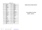
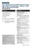
Operating Instructions
ProVicom MT-65, MT-125
R. STAHL HMI Systems GMBH
Im Gewerbegebiet Pesch 14
50767 Köln
Version
Issue:
© R. STAHL HMI Systems GmbH / OperatingInstruction_Provicom_Falcon_en_1_7.doc / 21.07.2008
1.7
21.07.2008
Page 1 of 15
Preface
Operating Instructions ProVicom
Table of contents
1
2
2.1
2.2
2.2.1
2.2.1.1
2.2.2
2.2.2.1
2.3
2.3.1
2.3.2
2.4
2.4.1.1
2.5
2.6
3
3.1
3.2
3.3
4
5
5.1
5.2
5.3
6
6.1
6.2
7
7.1
8
9
9.1.1
9.1.2
10
10.1
10.1.1
11
Description
Preface
Provicom MT-65, MT-125
Device function
Product identification
For Zone 2
Identification number
For Zone 22
Product identification for MT-65 / MT-125
Special conditions
Zone 2
Zone 22
Warnings / notes
Note concerning use in Zone 22
Power supply
Type code
Installation and operation
General information
Installation in Zone 2 and Zone 22
MT-65, MT-125
Application
Assembly and disassembly
General information
MT-65, MT-125
Cut-out MT-xxx
Operation
Connections MT-xxx
Dip switch settings S1 and S3
Maintenance, service
Servicing
Troubleshooting
Disposal
ROHS directive 2002/95/EC
China ROHS
Certificates
Provicom MT-65, MT-125
Declaration of EC conformity
Release notes
Page 2 of 15
Page
3
3
3
4
4
4
5
5
6
6
6
6
6
7
7
8
8
8
8
8
9
9
9
9
10
10
11
12
12
12
13
13
13
14
14
14
15
© R. Stahl HMI Systems GmbH / OperatingInstruction_Provicom_Falcon_en_1_7.doc / 21.07.2008
Operating Instructions ProVicom
1
Preface
Preface
These operating instructions also cover Ex-relevant aspects.
2
Provicom MT-65, MT-125
2.1 Device function
The MT-65 and MT-125 operator interfaces are intelligent display and operating devices with
text or graphic display for use in hazardous environments of zones 2 and 22 according to ATEX
guideline 94/9/EC.
The easy and simple functions of the MT-65 guarantee less configuration time for your
application and reduce the workload of your PLC.
The MT-125 operator interface offers many different styles of graphic display. Its many
integrated functions also reduce the workload of your PLC.
)
LCD monochrome graphic display, 240x64 dot resolution (MT-65), 240x128 dot resolution
(MT-125)
)
)
)
LED (MT-65) or CFL (MT-125) backlight
)
)
Winbond W77IC32 processor, 22 MHz
)
)
)
)
)
)
)
)
RS-232-C programming and printer interface
)
Real time clock and data retention capacitor are buffered.
Keyboard: extended 10 block
MT-65
MT-125
16 blank function keys that can be customised, 4 softkeys
12 blank function keys that can be customized, 4 set function keys,
8 soft keys
Program memory 512 kByte RAM, data memory 512 kByte RAM (with 64 kByte boot
part), main memory 128 kByte RAM
Either RS-232, RS-422 or RS-485 communication interface
2nd serial interface: optional Profibus DP or MPI module
Reader interface via module if required
MT-65 temperature range:
–20 ... +70 °C
MT-125 temperature range: –10 ... +60 °C
24V DC power supply with reverse voltage protection
MT-65
MT-125
4 freely controllable LEDs and 16 function keys with LEDs in the frontplate
4 freely controllable LEDs and 12 function keys with LEDs in the frontplate
© R. Stahl HMI Systems GmbH / OperatingInstruction_Provicom_Falcon_en_1_7.doc / 21.07.2008
Page 3 of 15
Provicom MT-65, MT-125
Operating Instructions ProVicom
2.2 Product identification
The operator interfaces may only be installed according to the specifications on the type plate.
2.2.1 For Zone 2
Manufacturer:
Type code:
Ex classification:
R.STAHL HMI Systems GMBH
MT-65 / MT-125
MT-65:
e II 3 G Ex nA II T4 X -20°C ≤ Ta ≤ +70°C
MT-125:
e II 3 G Ex nA II T4 X -10°C ≤ Ta ≤ +60°C
2.2.1.1 Identification number
Id. number / description:
e II 3 G Ex nA II T4 X
-20°C ≤ Ta ≤ +70°C
Ambient temperature
Note special conditions
Temperature class 4 (135°C)
Gas group:
Application in groups A, B and C
Non-transmitting device
Type of protection normal operation
Surrounded by gas
Device category 3 (normal protection
type)
Device group II (for all devices NOT
used underground or in mines and thus
NOT surrounded by mine gas or
flammable dust particles)
Page 4 of 15
© R. Stahl HMI Systems GmbH / OperatingInstruction_Provicom_Falcon_en_1_7.doc / 21.07.2008
Operating Instructions ProVicom
Provicom MT-65, MT-125
2.2.2 For Zone 22
Non-conductive dust
Manufacturer:
Type code:
Ex classification:
Type code:
Ex classification:
R. STAHL HMI Systems GmbH
MT-65
e II 3 D EEx IP65 T85°C X
-20°C ≤ Ta ≤ +70°C
e II 3 D EEx IP65 T65°C X
-20°C ≤ Ta ≤ +50°C
MT-125
e II 3 D EEx IP65 T75°C X
-10°C ≤ Ta ≤ +60°C
e II 3 D EEx IP65 T65°C X
-10°C ≤ Ta ≤ +50°C
2.2.2.1 Product identification for MT-65 / MT-125
Product identification
e II 3 D EEx IP65 T85°C X
-20°C ≤ Ta ≤ +70°C
Ambient temperature
Note special conditions
Maximum surface temperature
Protection against dust ingress (IP6X)
Surrounded by non-conductive dust
Device category 3 (normal protection
type)
Device group II (for all devices NOT
used underground or in mines and thus
NOT surrounded by mine gas or
flammable dust particles)
)
Note concerning Zone 22:
MT-65:
• When the device is in operation in an ambient temperature
Ta = -20°C to +70°C, the surface temperature will not exceed +85°C.
• When the device is in operation in an ambient temperature
Ta = -20°C to +50°C, the surface temperature will not exceed +65°C.
MT-125:
• When the device is in operation in an ambient temperature
Ta = -10°C to +60°C, the surface temperature will not exceed +75°C.
• When the device is in operation in an ambient temperature
Ta = -10°C to +50°C, the surface temperature will not exceed +65°C.
© R. Stahl HMI Systems GmbH / OperatingInstruction_Provicom_Falcon_en_1_7.doc / 21.07.2008
range
of
range
of
range
of
range
of
Page 5 of 15
Provicom MT-65, MT-125
Operating Instructions ProVicom
2.3 Special conditions
2.3.1 Zone 2
1.
2.
3.
4.
This device is classified as a non-sparking apparatus with low power consumption.
The device housing must be of at least protection type IP54 at the point of assembly.
The devices must not be exposed to direct sunlight permanently.
The error output (relay contact) must NOT be connected.
2.3.2 Zone 22
The device housing must adhere to the EN 50281 requirements (such as the type 8146 or
8125 housings by R. STAHL Schaltgeräte GmbH).
2.4 Warnings / notes
Warning !
The error output (relay contact) must NOT be connected if the operator interfaces are
installed in zone 2 !
Warning !
“Do not open device when switched on”
Warning !
“Do not remove fuse when device is switched on”
Warning !
“Do not remove connector when device is switched on”
)
Note:
“External leads must not be connected under strain”
2.4.1.1 Note concerning use in Zone 22
)
Note:
During assembly and operation of the operator interface electrostatic surface voltages
must not exceed those caused by manual rubbing.
Page 6 of 15
© R. Stahl HMI Systems GmbH / OperatingInstruction_Provicom_Falcon_en_1_7.doc / 21.07.2008
Operating Instructions ProVicom
Provicom MT-65, MT-125
2.5 Power supply
Operator
interface
MT-65
MT-125
Power supply
Minimum
Nominal voltage
Maximum
19,2 VDC
24 VDC
28,8 VDC
Current
consumption
Maximum
105 mA
215 mA
2.6 Type code
Type code:
Provicom MT-xxx
65 / 125
Product type:
Version
MT-xxx-RS232
MT-xxx-RS422
MT-xxx- RS422-DP
MT-xxx- RS422-MPI
MT-xxx-RS
MT-xxx-WCR
Description
Type with
RS-232 interface
RS-422 interface
RS-422 and Profibus-DP interface
RS-422 and MPI interface
RS interface for barcode or proximity reader
WCR interface for Wiegand Effect reader
© R. Stahl HMI Systems GmbH / OperatingInstruction_Provicom_Falcon_en_1_7.doc / 21.07.2008
Page 7 of 15
Installation and operation
3
Operating Instructions ProVicom
Installation and operation
3.1 General information
Electrical installations are subject to the relevant regulations for installation and operation.
3.2 Installation in Zone 2 and Zone 22
The users of electrical installations in hazardous environments must ensure that the equipment
is kept in proper condition, is operated according to instructions and that maintenance and
repairs are carried out. (RL 1999/92/EC, RL 94/9EC, IEC/EN 60079-14 are some of the
regulations that apply).
However, any repairs should always be carried out by the manufacturer.
3.3 MT-65, MT-125
• The operator interfaces may be installed in zones 2 and 22 (non-conductive dusts).
• The devices are constructed according to protection type IP65 and must be protected
accordingly from adverse environmental conditions such as splashed water or dirt
exceeding pollution degree 2.
• Users must adhere to the “Special Conditions”. Also of importance are the authorized
electrical operating values.
• The external PA/l must be connected. The PA-connector had to be connected to the
equipotential bonding system. A connection is provided on the back of the terminal
housing for this purpose.
• The PA-connector must be connected to the equipotential bonding conductor of the
hazardous area.
4
Application
The devices may only be used for the purposes detailed above and in accordance with current
regulations; otherwise, the manufacturer’s warranty shall become null and void !
In case of incorrect or unauthorised use or non-compliance with the instructions in this manual
the manufacturer’s warranty will become null and void !
No changes may be made to the devices or their components that compromise explosion
protection.
The devices may only be installed and operated in an undamaged, dry and clean condition.
Page 8 of 15
© R. Stahl HMI Systems GmbH / OperatingInstruction_Provicom_Falcon_en_1_7.doc / 21.07.2008
Operating Instructions ProVicom
5
Assembly and disassembly
Assembly and disassembly
5.1 General information
Assembly and disassembly are subject to general technical rules. Additional, specific safety
regulations apply to electronic and pneumatic installations. In Germany, for example, these
include the BGI 547 (Information on and principles of workplace safety and health issued by the
Government Safety Association).
5.2 MT-65, MT-125
When installing the device, particular care shall be taken that:
• the device has been properly installed according to instructions,
• the device is undamaged,
• all screws are tightened fast,
• the device’s external bonding terminal is properly connected to the exponential bonding
system at its place of use.
5.3 Cut-out MT-xxx
Make a cut-out with the following dimensions:
Device
Width
Height
MT-65
MT-125
275.0 ± 0.5 mm
300.0 ± 0.5 mm
131.0 ± 0.5 mm
180.0 ± 0.5 mm
Installation
depth
max. 80 mm
max. 80 mm
Material thickness
up to 10 mm
up to 10 mm
© R. Stahl HMI Systems GmbH / OperatingInstruction_Provicom_Falcon_en_1_7.doc / 21.07.2008
Page 9 of 15
Operation
6
Operating Instructions ProVicom
Operation
6.1 Connections MT-xxx
Plug
X1
X2
X3
Pin
1
2
3
1
2
3
4
5
6
1
2
X4
1
2
3
4
5
6
7
8
9
*
**
Definition
Power supply operator interface + 24V
N.C. *
Power supply operator interface GND
N.C. *
RxD
TxD
N.C. *
GND
CTS
Relay contact
Relay contact
RS-232
RS-422 / RS-485
N.C. *
N.C. *
TxD
N.C. *
RxD
TxD-B
N.C. *
RxD-B
GND
N.C. *
N.C. *
RxD-A
CTS
N.C. *
RTS
N.C. *
N.C. *
TxD-A
Connection
Power supply
of operator
interface
Programming and
Printer interface
RS-232
Error output **
Communication
interface
RS-232 or
RS-422/485
Not Connected
Warning:
The error output (relay contact) must NOT be connected if the operator interfaces are
installed in zone 2.
X14 Plug
Version
L2DP
Version
MPI
Page 10 of 15
Pin
3
4
5
6
8
3
4
5
6
8
9
Definition
RxD/TxD-P
RTS
M5V2
P5V2
RxD/TxD-N
RxD/TxD-P
RTS/AS
GND
P5V2
RxD/TxD-N
RTS PG
Connection
Communication
Profibus-DP
Communication
MPI
© R. Stahl HMI Systems GmbH / OperatingInstruction_Provicom_Falcon_en_1_7.doc / 21.07.2008
Operating Instructions ProVicom
Operation
6.2 Dip switch settings S1 and S3
S1.1
S1.2
S1.3
S1.4
S1.5
S1.6
S1.7
S1.8
on
on
off
off
off
off
off
on
S3.1
S3.2
S3.3
S3.4
S3.5
on
off
S3.6
off
on
on
on
off
off
on
on
off
off
off
X
off
Definition
Configuration menu
released / activated
Delete text memory
Reserve
Standard settings
Definition
RS-232
RS-422/RS-485
RS-4xx RxD
Terminating bus resistor and
termination switched on
RS-4xx RxD
Terminating bus resistor and
termination switched off
RS-4xx TxD
Terminating bus resistor and
termination switched on
RS-4xx TxD
Terminating bus resistor and
termination switched off
© R. Stahl HMI Systems GmbH / OperatingInstruction_Provicom_Falcon_en_1_7.doc / 21.07.2008
Page 11 of 15
Maintenance, service
7
Operating Instructions ProVicom
Maintenance, service
Because the transmission of the devices remains reliable and stable over long periods of time,
regular adjustments are not required.
• Only original parts provided by the manufacturer must be used.
• Fuses may only be replaced by equivalent fuse types.
System maintenance should focus on the following:
a. Seal wear
b. Monitor damage
c. All screws are tightened fast
d. All cables and lines are properly connected and undamaged
)
Note:
Associated equipment is subject to maintenance, service and testing according to
guidelines 1999/92/EC, IEC 60079-19 and EN 60079-17 as well as EN 50281-1-2
(Zone 22) !
7.1 Servicing
In accordance with IEC 60079-19 and EN 60079-17, operators of electric plants in hazardous
areas are obliged to have them serviced by qualified electricians.
8
Troubleshooting
Devices operated in hazardous areas must not be modified. Repairs may only be carried out by
qualified, authorized staff specially trained for this purpose.
)
Repairs may only be carried out by specially trained staff who are familiar with all basic
conditions of the applicable user regulations and – if requested – have been authorized by
the manufacturer.
Page 12 of 15
© R. Stahl HMI Systems GmbH / OperatingInstruction_Provicom_Falcon_en_1_7.doc / 21.07.2008
Operating Instructions ProVicom
9
Disposal
Disposal
Disposal of packaging and used parts is subject to regulations valid in whichever country the
device has been installed.
The disposal of equipment sold after August 13th, 2005, and installed in countries under the
jurisdiction of the EU is governed by directive 2002/96/EC on waste electrical and electronic
equipment (WEEE). Under this directive, operator interfaces are classified as part of category 9
(monitoring and control instruments).
We shall take back our equipment according to our General Terms and Conditions.
9.1.1 ROHS directive 2002/95/EC
The prohibition of hazardous substances as detailed in directive 2002/95/EC on the restriction
of the use of certain hazardous substances (ROHS) does not apply to electronic equipment of
categories 8 and 9, and is therefore not applicable to the equipment described in these
operating instructions.
9.1.2 China ROHS
According to a new administrative rule introduced in China 01.03.2007 all devices containing
hazardous substances must be labelled accordingly.
The following applies to the MT-65 / MT-125 operator interfaces:
Names and Contents of Toxic or Hazardous Substances or Elements
Part
Name
Lead
Housing
Display
all PCBs
Misc.
(Pb)
O
O
X
O
Toxic or hazardous Substances and Elements
PolyPolyHexaMercury Cadmium
brominated
brominated
valent
Chromium biphenyls diphenyl ethers
(PBDE)
(PBB)
(Cr (VI))
(Cd)
(Hg)
O
O
O
O
O
O
O
O
O
O
O
O
O
O
O
O
O
O
O
O
O
Indicates that this toxic or hazardous substance contained in all of the homogeneous
materials for this part is below the limit requirement in SJ/T11363-2006.
X
Indicates that this toxic or hazardous substance contained in at least one of the
homogeneous materials used for this part is above the limit requirement in
SJ/T11363-2006.
© R. Stahl HMI Systems GmbH / OperatingInstruction_Provicom_Falcon_en_1_7.doc / 21.07.2008
Page 13 of 15
Certificates
Operating Instructions ProVicom
10 Certificates
10.1 Provicom MT-65, MT-125
10.1.1 Declaration of EC conformity
Page 14 of 15
© R. Stahl HMI Systems GmbH / OperatingInstruction_Provicom_Falcon_en_1_7.doc / 21.07.2008
Operating Instructions ProVicom
Release notes
11 Release notes
Starting with the version 1.7 of these operating instruction the chapter "Release notes" is
implemented. In this chapter you can find the respective changes which was done regarding
this document version.
Version 1.7
•
•
•
•
•
Changing the marking of the operator interfaces according to ATEX
Replacement of EC - Declaration of Conformity
Changing of the definition from the type code to the actual one
Changing information to BGI 547
Formal improvement
© R. Stahl HMI Systems GmbH / OperatingInstruction_Provicom_Falcon_en_1_7.doc / 21.07.2008
Page 15 of 15