1
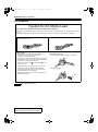
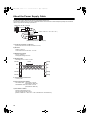
AG-BS300P_E(VQT2H41)_E.book 1 ページ 2009年10月23日 金曜日 午後6時8分 Operating Instructions Base Station Before operating this product, please read the instructions carefully and save this manual for future use. F0909T0 -F @ Printed in Japan ENGLISH VQT2H41 AG-BS300P_E(VQT2H41)_E.book 2 ページ 2009年10月23日 金曜日 午後6時8分 Read this first ! For AG-BS300P CAUTION RISK OF ELECTRIC SHOCK DO NOT OPEN CAUTION: TO REDUCE THE RISK OF ELECTRIC SHOCK, DO NOT REMOVE COVER (OR BACK). NO USER SERVICEABLE PARTS INSIDE. REFER TO SERVICING TO QUALIFIED SERVICE PERSONNEL. The lightning flash with arrowhead symbol, within an equilateral triangle, is intended to alert the user to the presence of uninsulated “dangerous voltage” within the product’s enclosure that may be of sufficient magnitude to constitute a risk of electric shock to persons. The exclamation point within an equilateral triangle is intended to alert the user to the presence of important operating and maintenance (servicing) instructions in the literature accompanying the appliance. The mains plug of the power supply cord shall remain readily operable. The AC receptacle (mains socket outlet) shall be installed near the equipment and shall be easily accessible. To completely disconnect this equipment from the AC mains, disconnect the mains plug from the AC receptacle. CAUTION: In order to maintain adequate ventilation, do not install or place this unit in a bookcase, built-in cabinet or any other confined space. To prevent risk of electric shock or fire hazard due to overheating, ensure that curtains and any other materials do not obstruct the ventilation. CAUTION: WARNING: y Keep the temparature inside the rack between 5 °C to 40 °C (41 °F to 104 °F). y To reduce the risk of fire or electric shock, do not expose this equipment to rain or moisture. y Bolt the rack security to the floor so that it will not topple over when the unit is drawn out. y To reduce the risk of fire or electric shock, keep this equipment away from all liquids. Use and store only in locations which are not exposed to the risk of dripping or splashing liquids, and do not place any liquid containers on top of the equipment. WARNING: This equipment must be grounded. To ensure safe operation, the three-pin plug must be inserted only into a standard three-pin power outlet which is effectively grounded through normal household wiring. Extension cords used with the equipment must have three cores and be correctly wired to provide connection to the ground. Wrongly wired extension cords are a major cause of fatalities. The fact that the equipment operates satisfactorily does not imply that the power outlet is grounded or that the installation is completely safe. For your safety, if you are in any doubt about the effective grounding of the power outlet, please consult a qualified electrician. WARNING: Always keep accessories (screws) out of the reach of babies and small children. indicates safety information. 2 CAUTION: CAUTION: To reduce the risk of fire or electric shock and annoying interference, use the recommended accessories only. CAUTION: Excessive sound pressure from earphones and headphones cause hearing loss. CAUTION: This apparatus can be operated at a voltage in the range of 100 - 240 V AC. Voltages other than 120 V are not intended for U.S.A. and Canada. CAUTION: Operation at a voltage other than 120 V AC may require the use of a different AC plug. Please contact either a local or foreign Panasonic authorized service center for assistance in selecting an alternate AC plug. AG-BS300P_E(VQT2H41)_E.book 3 ページ 2009年10月23日 金曜日 午後6時8分 Read this first ! (continued) For AG-BS300P IMPORTANT SAFETY INSTRUCTIONS 1) Read these instructions. 2) Keep these instructions. 3) Heed all warnings. 4) Follow all instructions. 5) Do not use this apparatus near water. 6) Clean only with dry cloth. 7) Do not block any ventilation openings. Install in accordance with the manufacturer’s instructions. 8) Do not install near any heat sources such as radiators, heat registers, stoves, or other apparatus (including amplifiers) that produce heat. 9) Do not defeat the safety purpose of the polarized or grounding-type plug. A polarized plug has two blades with one wider than the other. A grounding-type plug has two blades and a third grounding prong. The wide blade or the third prong are provided for your safety. If the provided plug does not fit into your outlet, consult an electrician for replacement of the obsolete outlet. 10) Protect the power cord from being walked on or pinched particularly at plugs, convenience receptacles, and the point where they exit from the apparatus. 11) Only use attachments/accessories specified by the manufacturer. 12) Use only with the cart, stand, tripod, bracket, or the table specified by the manufacturer, or sold with the apparatus. When a cart is used, use caution when moving the cart/apparatus combination to avoid injury from tip-over. 13) Unplug this apparatus during lightning storms or when unused for long periods of time. 14) Refer all servicing to qualified service personnel. Servicing is required when the apparatus has been damaged in any way, such as power-supply cord or plug is damaged, liquid has been spilled or objects have fallen into the apparatus, the apparatus has been exposed to rain or moisture, does not operate normally, or has been dropped. S3125A FCC Note: This equipment has been tested and found to comply with the limits for a class B digital device, pursuant to Part 15 of the FCC Rules. These limits are designed to provide reasonable protection against harmful interference in a residential installation. This equipment generates, uses, and can radiate radio frequency energy and, if not installed and used in accordance with the instruction manual, may cause harmful interference to radio communications. However, there is no guarantee that interference will not occur in a particular installation. If this equipment does cause harmful interference to radio or television reception, which can be determined by turning the equipment off and on, the user is encouraged to try to correct the interference by one or more of the following measures: z Reorient or relocate the receiving antenna. z Increase the separation between the equipment and receiver. z Connect the equipment into an outlet on a circuit different from that to which the receiver is connected. z Consult the dealer or an experienced radio/TV technician for help. The user may find the booklet “Something About Interference” available from FCC local regional offices helpful. Warning : To assure continued FCC emission limit compliance, follow the attached installation instructions and the user must use only shielded interface cables when connecting to peripheral devices. Also any unauthorized changes or modifications to this equipment could Void the userís authority to operate this device. 3 AG-BS300P_E(VQT2H41)_E.book 4 ページ 2009年10月23日 金曜日 午後6時8分 Read this first ! (continued) For AG-BS300E Caution for AC Mains Lead FOR YOUR SAFETY PLEASE READ THE FOLLOWING TEXT CAREFULLY. This product is equipped with 2 types of AC mains cable. One is for continental Europe, etc. and the other one is only for U.K. Appropriate mains cable must be used in each local area, since the other type of mains cable is not suitable. FOR CONTINENTAL EUROPE, ETC. Not to be used in the U.K. FOR U.K. ONLY This appliance is supplied with a moulded three pin mains plug for your safety and convenience. A 13 amp fuse is fitted in this plug. Should the fuse need to be replaced please ensure that the replacement fuse has a rating of 13 amps and that it is approved by ASTA or BSI to BS1362. Check for the ASTA mark or the BSI mark on the body of the fuse. If the plug contains a removable fuse cover you must ensure that it is refitted when the fuse is replaced. If you lose the fuse cover the plug must not be used until a replacement cover is obtained. A replacement fuse cover can be purchased from your local Panasonic Dealer. indicates safety information. EEE Yönetmeliğine Uygundur. EEE Complies with Directive of Turkey. 4 FOR U.K. ONLY How to replace the fuse 1. Open the fuse compartment with a screwdriver. 2. Replace the fuse. Fuse AG-BS300P_E(VQT2H41)_E.book 5 ページ 2009年10月23日 金曜日 午後6時8分 Read this first ! (continued) For AG-BS300E WARNING: CAUTION: THIS EQUIPMENT MUST BE EARTHED. To ensure safe operation, the three-pin plug must be inserted only into a standard three-pin power point which is effectively earthed through normal household wiring. Extension cords used with the equipment must have three cores and be correctly wired to provide connection to the earth. Wrongly wired extension cords are a major cause of fatalities. The fact that the equipment operates satisfactorily does not imply that the power point is earthed or that the installation is completely safe. For your safety, if you are in any doubt about the effective earthing of the power point, please consult a qualified electrician. In order to maintain adequate ventilation, do not install or place this unit in a bookcase, built-in cabinet or any other confined space. To prevent risk of electric shock or fire hazard due to overheating, ensure that curtains and any other materials do not obstruct the ventilation. WARNING: y To reduce the risk of fire or electric shock, do not expose this equipment to rain or moisture. y To reduce the risk of fire or electric shock, keep this equipment away from all liquids. Use and store only in locations which are not exposed to the risk of dripping or splashing liquids, and do not place any liquid containers on top of the equipment. WARNING: Always keep accessories (screws) out of the reach of babies and small children. CAUTION: y Keep the temparature inside the rack between 5 °C to 40 °C. y Bolt the rack security to the floor so that it will not topple over when the unit is drawn out. CAUTION: To reduce the risk of fire or electric shock and annoying interference, use the recommended accessories only. CAUTION: Excessive sound pressure from earphones and headphones cause hearing loss. CAUTION: Do not remove panel covers by unscrewing them. To reduce the risk of electric shock, do not remove the covers. No user serviceable parts inside. Refer servicing to qualified service personnel. CAUTION: The mains plug of the power supply cord shall remain readily operable. The AC receptacle (mains socket outlet) shall be installed near the equipment and shall be easily accessible. To completely disconnect this equipment from the AC mains, disconnect the mains plug from the AC receptacle. indicates safety information. 5 AG-BS300P_E(VQT2H41)_E.book 6 ページ 2009年10月23日 金曜日 午後6時8分 Read this first ! (continued) EMC NOTICE FOR THE PURCHASER/USER OF THE APPARATUS 1. Applicable standards and operating environment (AG-BS300E) The apparatus is compliant with: z standards EN55103-1 and EN55103-2 1996.11, and z electromagnetic environments E1, E2, E3, and E4. 2. Pre-requisite conditions to achieving compliance with the above standards <1> Peripheral equipment to be connected to the apparatus and special connecting cables z The purchaser/user is urged to use only equipment which has been recommended by us as peripheral equipment to be connected to the apparatus. z The purchaser/user is urged to use only the connecting cables described below. <2> For the connecting cables, use shielded cables which suit the intended purpose of the apparatus. z Video signal connecting cables Use double shielded coaxial cables, which are designed for 75-ohm type high-frequency applications, for SDI (Serial Digital Interface). Coaxial cables, which are designed for 75-ohm type high-frequency applications, are recommended for analog video signals. z Audio signal connecting cables If your apparatus supports AES/EBU serial digital audio signals, use cables designed for AES/EBU. Use shielded cables, which provide quality performance for high-frequency transmission applications, for analog audio signals. z Other connecting cables (IEEE1394, USB) Use shielded cables, which provide quality performance for high-frequency applications, as connecting cables. z When connecting to the DVI signal terminal, use a cable with a ferrite core. z If your apparatus is supplied with ferrite core(s), they must be attached on cable(s) following instructions in this manual. 3. Performance level The performance level of the apparatus is equivalent to or better than the performance level required by these standards. However, the apparatus may be adversely affected by interference if it is being used in an EMC environment, such as an area where strong electromagnetic fields are generated (by the presence of signal transmission towers, cellular phones, etc.). In order to minimize the adverse effects of the interference on the apparatus in cases like this, it is recommended that the following steps be taken with the apparatus being affected and with its operating environment: 1. Place the apparatus at a distance from the source of the interference. 2. Change the direction of the apparatus. 3. Change the connection method used for the apparatus. 4. Connect the apparatus to another power outlet where the power is not shared by any other appliances. 6 AG-BS300P_E(VQT2H41)_E.book 7 ページ 2009年10月23日 金曜日 午後6時8分 Table of Contents Read this first ! ........................................................2 Supplied Accessories.............................................7 Features ...................................................................7 System Configuration Diagram .............................8 Precautions When Connecting the System..........9 Camera Extension System and Camera Recorder Configuration Example..........10 Connection with the AG-HPX300/301/302/304 ........... 10 Connection with camera recorders other than AG-HPX300/301/302/304 or AG-HPX500/502 ............11 Connection with the AG-HPX500/502 ......................... 12 About the Signals to Input to GENLOCK IN Connector.............................................................. 16 About the RET Signal ........................................... 16 About the Rack Mount.......................................... 17 Setting up the camera recorder........................... 17 About the Power Supply Cable ........................... 18 Menu Display......................................................... 19 List of Menus......................................................... 20 Connector Signals ................................................22 Specifications ....................................................... 23 Part Names and Functions...................................13 Front Panel.................................................................. 13 Rear Panel .................................................................. 14 Supplied Accessories AC cable (AG-BS300P) a 1 AC cables (AG-BS300E) a 2 Rack Mount Adapters a 2 Rack Mount Adapter Screws a 6 Features This unit has the following features: z The unit is connected to the camera adapter (AG-CA300G; optional) by a power cable (refer to page 18 for specification) and two BNC cables, and works to supply power to the camera recorder side and transmit the video and audio signals recorded using the camera recorder. z It is possible to transfer one line of the return video (RET). (2 lines of transfer are possible depending on the mode.) z It is possible to transfer one line of the intercom (INCOM). z It is possible to transfer the remote control signal. z The transmission between this unit and the camera adapter uses a non-compressed digital signal, so transmission without any degradation of the video and audio signals is possible. z It is possible to extend the length of the cable between this unit and the camera adapter up to 100 m. (When using BNC cable: 5C-FW) z DC operation is possible. (However, power supply to the camera adapter is not possible.) z The unit is compatible with multi-format. 7 AG-BS300P_E(VQT2H41)_E.book 8 ページ 2009年10月23日 金曜日 午後6時8分 System Configuration Diagram RET OUT Monitor SDI OUT ° 2 VIDEO OUT (Composite signal) VF/return video VF OUT BT-LH80W/WU BS IN Dedicated cable (monitor video, GPI) BS OUT Intercom tally CA IN Return (SDI) BNC ° 2 Use 5C-FW (Maximum extension length: 100 m) REMOTE Remote cable (control, monitor video) CA OUT SDI IN K GENLOC OUT RET OUT Return (Composite signal) CALL RET RET CTRL IN BS OUT GENLOCK REMO TE REMOTE SDI OUT2 AG-HPX300/ 301/302/304 DC IN 24 V AG-CA300G SDI IN Main line SDI video (BNC) GENLOCK IN DC OUT 24 V AG-BS300P/E Power supply cable (Refer to page 18) Resistance: Use 0.5 h or less (Maximum extension length: 100 m) GENLOCK LOOPOUT AC IN DC IN 24 V GENLOCK OUT GENLOCK (BNC) Anton/Bauer Hytron, Trimpac AG-EC4G AJ-RC10G IDX A-AB2E IDX ENDURA7/10 <Notes> z Be sure to connect cables 1 - 6 shown above. z Other compatible camera: AJ-HPX3700G, AJ-HPX3000G, AJ-HPX2700G, AJ-HPX2000/2100, AG-HPX500/502, AJ-HDX900P/E 8 AG-BS300P_E(VQT2H41)_E.book 9 ページ 2009年10月23日 金曜日 午後6時8分 Precautions When Connecting the System Take caution with the following when connecting the camera adapter and this unit. z To connect the camera adapter and the unit, use a power supply cable of the specification described in [About the Power Supply Cable] (page 18). When connecting and disconnecting the power supply cable, always ensure that the power is switched OFF. z INCOM becomes disconnected temporarily when the video format is changed on the camera recorder. z Use the 5C-FW for the BNC cable. Maximum extension distance of 100 m cannot be achieved if any other cable is used. z When the video format on the camera recorder is 720P, there will be misalignment of ±1 field between the TC (time code) that is superimposed on the SDI signal and the video signal, even if the composite signal is input to the GENLOCK IN signal connector of this unit, since the 720P signal is a field unit signal. Displacement of ±1 field will occur between the VBS output from the camera recorder and this unit. z Turn the power of this unit and the camera adapter OFF once and turn it back ON after the video format of the camera recorder has changed. z When confirming the RET signal on the camera adapter by inputting the RET signal into this unit, the image on the viewfinder (LCD monitor) may be interrupted for an instant at the moment the RET signal selection switch on the camera adapter is pressed. z Only a dynamic microphone can be used as the microphone for INCOM. z Most of the operational functions of the camera recorder will be controlled by the remote control unit (AG-EC4G; optional, or AJ-RC10G; optional) when the remote control unit is connected to this unit, and the remote control unit is enabled by turning the power on. (However, POWER ON/ OFF, AWB/ABB, MODE CHECK, REC START/STOP, FF and REW can also be operated from the camera recorder.) z Operation by the camera recorder will be enabled when the remote control unit is connected to this unit and disabled. z When this unit is used in combination with the camera adapter and the camera recorder, connect the cables 1 6 as shown on page 8. Also, set the GENLOCK item to “EXT” using the GENLOCK menu of the camera recorder. (This setting is not necessary for AG-HPX300/301/302/ 304 and AG-HPX500/502 since it is set to “EXT” mode automatically.) Also, set the GL PHASE item to “HD SDI”. When this unit is used connected to the AG-HPX500/502, set the GL SELECT item to “SDI”, and the GL PHASE item to “OFF”. z There is only one line of video signal sent from the camera adapter to this unit. It is not possible to view the camera recorder viewfinder image via the VIDEO OUT (MENU) connector or the SDI OUT 1/2 connector of this unit. z This unit does not have a built in color generator etc., and a video signal will not be output from the VIDEO OUT (MENU) connector or SDI OUT 1/2 connector if only the unit is supplied with power. z Video output signal of this unit may be interrupted when the power is turned on, but this is not a malfunction. z When the cable 1, 2, 3, 4, 5, or 6 shown in page 8 is disconnected while operating, reconnect the cable correctly, and turn the power back on. z When the camera recorder connected to this unit is set to 1080/23.98PsF, 1080/24PsF, or 720/60P, the down converted signal from the VIDEO OUT (MENU) connector of this unit is not output. (25IRE NTSC signal to display the menu is output.) Also, it is not possible to input a composite signal as a RET signal. z When this unit is used connected with the camera adapter and the camera recorder, only CH1 - CH4 of the embedded audio for the SDI signal of this unit is output. z When this unit, the camera adapter and the AG-HPX500/ 502 are combined in a system and the AG-HPX500/502 is set to play back video, or put into the IEEE1394 mode, the synchronization between this unit’s VIDEO OUT signal and SDI OUT 1/2 signal may be lost. Similarly, when the AG-HPX500/502 is put into playback mode or IEEE1394 mode etc., noise may appear in the INCOM signal. For these reasons, in systems combining this unit, the camera adapter, and the AG-HPX500/502, the AG-HPX500/502 should not be used in playback mode or IEEE1394 mode. z When this unit, the camera adapter and the AG-HPX500/ 502 are combined in a system and the AG-HPX500/502 is put into MCR mode, the output from the unit will be a dark screen and video will not be displayed except during playback by the AG-HPX500/502. z Do not perform version update of the camera recorder while this unit, the camera adapter, and the camera recorder are connected. Perform the version update of the camera recorder with the camera recorder on its own. z When combining this unit with the camera recorder, ensure that the output format of the SDI signal matches the system format of the camera recorder. z Turn on the power of the remote control unit after turning on the power for this unit when the remote control unit is connected to this unit. z Turn on the power after connecting the power supply cable and BNC cables. 9 AG-BS300P_E(VQT2H41)_E.book 10 ページ 2009年10月23日 金曜日 午後6時8分 Camera Extension System and Camera Recorder Configuration Example Connection with the AG-HPX300/301/302/304 AG-CA300G AG-BS300P/E RET switch GPI BT-LH80W/WU VF OUT SDI IN SDI OUT2 AG-HPX300/ 301/302/304 Separation BS IN CA OUT RET SDI (signal A) YPBPR SDI OUT1 GENLOCK IN GENLOCK OUT Multiplex BS OUT SDI IN RET (signal B) VIDEO Decoder * CA IN REMOTE RET signal selection switch SDI OUT1 SDI OUT2 REMOTE (signal B) RET OUT VIDEO IN Prompter * VIDEO signal will be converted to component signal. z Use BT-LH80W/WU as a monitor. z When the video format of the AG-HPX300/301/302/304 is HD format, the RET signal selection switch on the unit does not work and the RET VIDEO signal is output constantly from the RET OUT connector of the camera adapter. The RET SDI signal is not output. z When the video format of the AG-HPX300/301/302/304 is SD format, the RET signal is selected to be the RET SDI signal or the RET VIDEO signal. The selection is made using the RET signal selection switch on the unit. Also, the RET signal output from the VF OUT connector of the camera adapter is the signal selected on this unit. z Video recording on the AG-HPX300/301/302/304 is sent to camera adapter via the REMOTE cable of the AG-HPX300/301/302/304, and the VIDEO signal (composite signal) is converted to component signal by the camera adapter. z Video signal selected by the RET switch of the camera adapter is output from the VF OUT connector of the camera adapter. RET signal is output when the RET switch is pushed, and the signal from the AG-HPX300/ 301/302/304 is output when the switch is not pushed. z If it is not necessary to display the camera status signal while displaying the video being recorded by the AG-HPX300/301/302/304 on the BT-LH80W/WU, it is possible to change the video being recorded to SDI signal by supplying SDI2 output or SDI1 output of the AG-HPX300/301/302/304 to the BT-LH80W/WU, and selecting the INPUT SEL.SDI in the GPI4 item of the BT-LH80W/WU. 10 z The camera extension system including this unit can send back 2 lines of signals, RET SDI signal and RET VIDEO signal of this unit, to the camera adapter simultaneously, when the video format of the AG-HPX300/301/302/304 is HD format. The RET VIDEO signal sent back to the camera adapter will be output from the RET OUT connector, so it can be used as a prompter signal or on-air monitor signal. z When the VIDEO signal is selected by the RET signal selection switch of this unit, RET VIDEO signal will be the only return signal from this unit to the camera adapter. The VF OUT connector of the camera adapter outputs an SD component signal resulting from the conversion of the RET VIDEO signal (composite). The RET OUT connector of the camera adapter outputs the RET VIDEO signal (composite). z If the video format of theAG-HPX300/301/302/304 is SD, only 1 line of either RET SDI signal or RET VIDEO will be the return signal from this unit. The video signal output from the RET OUT connector of the camera adapter is the result of converting the RET signal selected using the RET signal selection switch to a composite signal. AG-BS300P_E(VQT2H41)_E.book 11 ページ 2009年10月23日 金曜日 午後6時8分 Camera Extension System and Camera Recorder Configuration Example (continued) Connection with camera recorders other than AG-HPX300/301/302/304 or AG-HPX500/502 AG-CA300G AG-BS300P/E RET switch GPI BT-LH80W/WU VF VF OUT Separation BS IN CA OUT YPBPR VF cable * 2 VF Camera recorder SDI1 GENLOCK IN GENLOCK OUT RET (signal B) VIDEO Decoder *1 CA IN REMOTE RET SDI (signal A) Multiplex BS OUT SDI IN RET signal selection switch SDI OUT1 SDI OUT2 REMOTE RET OUT (signal B) VIDEO IN Prompter *1 VIDEO signal will be converted to component signal. *2 Use the BT-CS80G. z Use BT-LH80W/WU as a monitor. z When the video format of the camera recorder is HD format, the RET signal selection switch on the unit does not work, and the RET OUT connector of the camera adapter outputs the RET VIDEO signal as normal. The RET SDI signal is not output. z When using the AJ-HPX2000/2100 or AJ-HPX3000G, use the unit menu to set the CAMERA VF item and the CRT VF item for the AJ-HPX2000/2100 or AJ-HPX3000G to match the type of viewfinder selected in the menu settings of the camera recorder. z When SD format has been set on a camera recorder which allows SD format as a video format (AJ-HPX2000/ 2100, AJ-HPX3000G), the RET signal is selected to be a RET SDI signal or a RET VIDEO signal. Selection of the signal is performed by the RET signal switching switch on this unit. Also, the RET signal output from the VF OUT connector of the camera adapter is the signal selected on this unit. z Signal output from the VF connector of the camera recorder for the video being recorded by the camera recorder is supplied to the VF connector of the BT-LH80W/WU via the VF cable (BT-CS80G; optional). z When the GPI4 item of the BT-LH80W/WU is set to INPUT SEL.VF, video signal selected by the RET switch of the camera adapter is output from the VF OUT connector of the camera adapter. When the RET switch is being pushed, the RET signal is output. When not being pushed, the signal from the VF OUT connector of the camera recorder is output. z If it is not necessary to display the camera status signal while displaying the video being recorded by the camera recorder on the BT-LH80W/WU, it is possible to change the video being recorded to SDI signal by supplying SDI2 output or SDI1 output of the camera recorder to the BT-LH80W/WU, and selecting the INPUT SEL.SDI in the GPI4 item of the BT-LH80W/WU. z The camera extension system including this unit can send back 2 lines of signals, RET SDI signal and RET VIDEO signal of this unit, to the camera adapter simultaneously, when the video format of the camera recorder is HD format. The RET VIDEO signal sent back to the camera adapter will be output from the RET OUT connector, so it can be used as a prompter signal or on-air monitor signal. z When the VIDEO signal is selected by the RET signal selection switch of this unit, RET VIDEO signal will be the only return signal from this unit to the camera adapter. The VF OUT connector of the camera adapter outputs an SD component signal resulting from the conversion of the RET VIDEO signal (composite). The RET OUT connector of the camera adapter outputs the RET VIDEO signal (composite). z When SD format has been set on a camera recorder which allows SD format as a video format (AJ-HPX2000/ 2100, AJ-HPX3000G), the RET signal from the unit is selected to be either an SDI signal or a RET VIDEO signal. The video signal output from the RET OUT connector of the camera adapter is a composite signal resulting from the conversion of the RET signal selection switch using the RET signal selection switch. 11 AG-BS300P_E(VQT2H41)_E.book 12 ページ 2009年10月23日 金曜日 午後6時8分 Camera Extension System and Camera Recorder Configuration Example (continued) Connection with the AG-HPX500/502 Viewfinder or BT-LH80W/WU AG-CA300G VF AG-YA500G VF OUT LENS CAM LENS Separation BS IN CA OUT RET signal selection switch RET SDI (signal A) CAM VF VF Lens AG-BS300P/E RET switch CA VF SDI1 AG-HPX500/ 502 GENLOCK IN Multiplex BS OUT SDI IN RET (signal B) VIDEO Decoder * GENLOCK OUT CA IN SDI OUT1 SDI OUT2 REMOTE REMOTE (signal B) RET OUT VIDEO IN Prompter * VIDEO signal will be converted to component signal. z Use the viewfinder included with the AG-HPX500/502 (dedicated for SD). Also, it is required to use the AGYA500G (optional). z Use the RET VIDEO signal as the RET signal. Selection of the signal is performed by the RET signal switching switch on this unit. Also, the RET signal output from the VF OUT connector of the camera adapter is the signal in SD format selected by this unit. When using a viewfinder, input the SD format signal into the RET IN SDI connector and RET IN VIDEO connector of the unit. z Video being recorded by the AG-HPX500/502 is supplied to the AG-YA500G from the VF connector of the AG-HPX500/502. z Video signal selected by the RET switch of the camera adapter is output from the VF OUT connector of the camera adapter.The RET signal is output from the VF connector of the AG-YA500G while the RET switch on the camera adapter or the RET switch on the lens is pushed, and the signal from the AG-HPX500/502 is output when it is not pushed. z The R TALLY LED on the viewfinder will light up while recording with the AG-HPX500/502, or when the R TALLY signal is supplied to this unit. z When the BT-LH80W/WU is used rather than the viewfinder included with the AG-HPX500/502, and the AG-YA500G VF connector is connected to the BT-LH80W/WU VF connector with the dedicated VF cable (BT-CS80G; optional), it is possible to input an HD SDI signal to the RET IN SDI signal connector of the unit and have the RET signal in HD format. 12 z When this unit, the camera adapter and the AG-HPX500/ 502 are combined in a system and the AG-HPX500/502 is put into MCR mode, the output from the unit will be a dark screen and video will not be displayed except during playback by the AG-HPX500/502. AG-BS300P_E(VQT2H41)_E.book 13 ページ 2009年10月23日 金曜日 午後6時8分 Part Names and Functions Front Panel 2 3 PUSH OPERATE INCOM INCOM LEVEL MIC TALLY/CALL ON MENU SEL ON POWER OFF OFF PIT ON Base Station AG-BS300 1 1. POWER switch This is the main power switch when using an AC power supply. It does not work when using a DC power supply. 2. POWER lamp This indicates that the main power supply (AC power supply) is turned on. 3. OPERATE lamp This indicates that this unit is operating. It will be as follows depending on the operation status of this unit. Light off: This indicates that main power supply is off or that the unit is initializing after the power has been switched on. Green light: This indicates that it is in normal operation status. Green flashing: This indicates the lock is being acquired by this unit, the camera adapter, or the camera recorder in cases such as right after power on. Red flashing: This indicates that the cables between this unit and the camera adapter or the cables between the camera adapter and the camera recorder (1, 2, 3, 4, or 5 on page 8) are not connected or there is a break in the cables. Check and reconnect the cables, and then turn the power of this unit OFF once and turn it back ON. Red light: This indicates that the fan motor is not revolving. If the fan stops turning during normal operation or otherwise behaves abnormally, consult a dealer. 4. INCOM connector Connect the headset for the intercom. Only a dynamic microphone can be used. Use a 3-meters or less cable. 5. INCOM volume level potentiometer This is a potentiometer to adjust the volume level of the intercom. 6. MIC switch This is the ON/OFF switch for the intercom microphone. There are three positions: ON/OFF/PTT*. 4 7. 5 6 7 8 9 TALLY lamp/CALL switch This is turned on while the TALLY signal is input to this unit. The TALLY lamp on the camera adapter will be turned on while this is pressed. TALLY lamp on the camera adapter and the TALLY lamp connected to the VF OUT connector of the camera adapter will be turned on when the TALLY signal is input to this unit, and there will be no change even if the CALL switch is pressed. <Note> The viewfinder connected to the VF connector of the camera recorder will not turn on even if the CALL switch is pressed. With camera recorders that can mount the viewfinder interface box (AG-YA500G; optional), it can be lighted up after mounting. However, it will also light up when the connected camera recorder is recording, so there will be no change even when the CALL switch is pushed. 8. MENU switch This is a switch to open the MENU to change the setting of this unit. Push for 3 seconds or more. 9. SEL switch This is a switch to select the settings of this unit from the MENU of this unit. *PTT (Push To talk): Microphone is turned on only while pushed.) 13 AG-BS300P_E(VQT2H41)_E.book 14 ページ 2009年10月23日 金曜日 午後6時8分 Part Names and Functions (continued) Rear Panel 13 17 DC OUT 24V 3 1 2 IN CA REMOTE OUT VIDEO OUT GEN LOCK IN LOOP OUT (MENU) RET IN VIDEO SDI 1 SDI OUT 2 INCOM/TALLY 4 V 1 2 3 4 5 6 7 8 9 10 1. DC OUT 24 V connector DC 24 V is output while this unit is operating with the AC power supply. This will supply DC power supply to the camera adapter. 24 V is not output when this unit is operating with the DC power supply. 2. CA IN connector Connect the BNC cable from the camera adapter. Connect with the BS OUT connector of the camera adapter using the BNC cable (5C-FW). 3. CA OUT connector Connect the BNC cable from the camera adapter. Connect with the BS IN connector of the camera adapter using the BNC cable (5C-FW). 4. GENLOCK IN connector This is a reference signal input connector to lock this unit with an external sync. <Note> Select the signal to input that matches the video format of the camera recorder. For details, refer to [About the Signals to Input to GENLOCK IN Connector] (page 16). 5. 6. GENLOCK LOOPOUT connector This is a loop through with the GENLOCK IN connector. VIDEO OUT (MENU) connector Composite signal is output. Color phase will be also locked to the reference signal when the BS signal (burst sync) is input as a reference signal into the GENLOCK IN connector. The down convert signal is not output from the VIDEO OUT (MENU) connector when the video format for the camera recorder is set to 1080-23.98PsF, 1080-24PsF or 720-60P. <Note> 25IRE NTSC signal is output to display menu. 7. 14 RET IN VIDEO signal connector This is an input connector for the return video signal from this unit to the camera adapter. This will input a composite signal. RET video cannot be viewed on the CRT viewfinder or color viewfinder when the video format is set to 23.98PsF or 1080-24PsF. When the system frequency is 59.94 Hz, be sure to match the SETUP menu settings of the camera and this unit to the SETUP level of the signal input to the RET IN VIDEO connector. 11 AC IN RTS VIDEO 12 14 15 8. DC IN 12V INCOM TALLY RET MAKE 4W SDI 16 18 RET IN SDI signal connector This is an input connector for the return video signal from this unit to the camera adapter. This will input a SDI signal. RET video cannot be viewed on the CRT viewfinder or color viewfinder when the video format for the camera recorder is set to 1080-23.98PsF or 1080-24PsF. <Note> For signals supplied to the 7.RET IN VIDEO signal connector and the 8.RET IN SDI signal connector and the signal output from the camera adapter, refer to [About the RET Signal] (page 16). 9. SDI OUT 1 connector This will output the SDI signal that was output from the camera recorder. 10. SDI OUT 2 connector This will output the SDI signal that was output from the camera recorder. Same signal as the signal output from SDI OUT 1 connector is output. 11. INCOM/TALLY connector This is a connector between this unit and the external intercom system and TALLY system. 12. TALLY selection switch This is a switch to match with the TALLY system connected to the 11.INCOM/TALLY connector. Select either contact or supplied voltage. For supplied voltage: It is compatible with 8 V - 12 V. MAKE: Select this when the TALLY input signal is a contact V: Select this when the TALLY input signal is a supplied voltage 13. INCOM selection switch This is a switch to match with the INCOM system connected to the INCOM/TALLY connector. Select either 4-wire format or RTS format. 4W: RTS: Select this when it is a 4-wire format Select this when it is a RTS format <Notes> z Set this switch to 4 W if the INCOM is not used and it is a system with this unit and a camera adapter connected one-to-one. z Make sure to connect to a RTS system when the switch is set to RTS. When using the RTS format, the 11.INCOM/TALLY connector should be terminated with 200 h between pin 7 and pin 8 (refer to page 22). AG-BS300P_E(VQT2H41)_E.book 15 ページ 2009年10月23日 金曜日 午後6時8分 Part Names and Functions (continued) 14. RET signal selection switch This is a switch to select the return signal from this unit to the camera adapter. Select the RET signal supplied to either the 7.RET IN VIDEO signal connector or the 8.RET IN SDI signal connector. 18. Cable hook This is used to prevent the AC power supply cable slipping off. SDI: Selects the SDI signal supplied to the 8.RET IN SDI signal connector. However, if the SDI is selected in HD mode, it is possible to transfer VIDEO signal simultaneously. The video output from the RET OUT connector of the camera adapter differs in HD format and SD format. For further details, refer to the operating instructions for the AG-CA300G. VIDEO:Selects the VIDEO signal supplied to the 7.RET IN VIDEO signal connector. 15. REMOTE connector Connect the AG-EC4G (optional) or the AJ-RC10G (optional), and controls the camera recorder. 16. DC IN 12 V connector External DC power supply is connected when operating this unit with DC. Use a power supply with a capacity of DC 12 V 3 A or higher. When using an external DC power, use a shielded cable 3 meters or shorter between the external DC power and this unit. This unit will go into DC operation status when the DC power supplying connector is connected to this connector. When only a DC power supply is supplied to this unit, DC 24 V is not output from the 1.DC OUT 24 V connector. DC 24 V is output from the 1.DC OUT 24 V connector only when the AC power is supplied to this unit. (Refer to page 22) _ Use of external DC power supply Make sure that the output voltage of the external DC power supply meets the rated voltage of the unit before making a connection. The output current of the external DC power supply should be large enough to provide the connected unit with its total amperage needs with a reasonable margin. Use the following formula to calculate the total amperage of the unit. total power consumption c voltage When the power is turned on, a rush current occurs. If the power supply is insufficient during this time, the unit may be damaged. Therefore, we recommend using an external DC power supply that provides at least twice the total power consumed by the unit. We also recommend using the proper DC cable recommended for your external DC power supply. z When using an external power supply other than the AC adapter, check the DC IN socket pin information to ensure correct polarity. If a +12 V power supply is accidentally connected to the GND terminal, this could cause a fire or personal injury. 17. AC IN connector This is a connector to supply AC power to this unit. This is connected to the power outlet using the attached AC power supply cable. 15 AG-BS300P_E(VQT2H41)_E.book 16 ページ 2009年10月23日 金曜日 午後6時8分 About the Signals to Input to GENLOCK IN Connector Supply the following signals to the GENLOCK IN connector, as a GENLOCK input signal to this unit, in accordance with the video format used. Video may be disrupted if any other signals are supplied. Video format of the camera recorder 1080/59.94i 1080/23.98PsF 1080/50i 1080/24PsF 720/59.94P 720/60P 720/50P 480/59.94i 576/50i Signal to be supplied to the GENLOCK IN connector (analog signal) When HD SYNC is supplied 1080/59.94i, 3-value SYNC When SD SYNC is supplied 480/59.94i, black burst signal (SYNC + burst) When HD SYNC is supplied 1080/23.98PsF, 3-value SYNC When SD SYNC is supplied Not supported When HD SYNC is supplied 1080/50i, 3-value SYNC When SD SYNC is supplied 576/50i, black burst signal (SYNC + burst) When HD SYNC is supplied 1080/24PsF, 3-value SYNC When SD SYNC is supplied Not supported When HD SYNC is supplied 720/59.94P, 3-value SYNC When SD SYNC is supplied 480/59.94i, black burst signal (SYNC + burst) When HD SYNC is supplied 720/60P, 3-value SYNC When SD SYNC is supplied Not supported When HD SYNC is supplied 720/50P, 3-value SYNC When SD SYNC is supplied 576/50i, black burst signal (SYNC + burst) When HD SYNC is supplied Not supported When SD SYNC is supplied 480/59.94i, black burst signal (SYNC + burst) When HD SYNC is supplied Not supported When SD SYNC is supplied 576/50i, black burst signal (SYNC + burst) <Note> When using the unit in HD mode, input the HD 3-value SYNC signal or black burst signal. When using the SD mode, input the black burst signal. When the SD 2-value SYNC signal without a burst signal is supplied, GENLOCK does not work. About the RET Signal The RET signal input to this unit can be transferred to the camera adapter. When the video format of the camera recorder is HD format, the video signal supplied to the RET IN SDI connector and the RET IN VIDEO connector can be transferred to the camera adapter. When the video format of the camera recorder is SD format, either of the video signals supplied to the RET IN SDI connector or the RET IN VIDEO connector can be transferred to the camera adapter. The signal output to the VF OUT connector (D-Sub connector) of the camera adapter can be switched with the RET signal selection switch at the rear panel of this unit. Video format of the camera recorder HD SD Input signal of the AG-BS300P/E Input signal connector name Input signal RET IN SDI HD SDl (signal A) RET IN VIDEO Composite (signal B) RET IN SDI HD SDl (signal A) RET IN VIDEO Composite (signal B) RET IN SDI SD SDl (signal C)*1 RET IN VIDEO Composite (signal B) RET IN SDI SD SDl (signal C)*1 RET IN VIDEO Composite (signal B) RET IN SDI SD SDl (signal A) RET IN VIDEO Composite (signal B) RET IN SDI SD SDl (signal A) RET IN VIDEO Composite (signal B) RET IN SDI HD SDl (signal C)*2 RET IN VIDEO Composite (signal B) RET IN SDI HD SDl (signal C)*2 RET IN VIDEO Composite (signal B) Output signal to the AG-CA300G RET signal selection VF OUT connector switch at the rear (D-Sub) SDI HD component (signal A) VIDEO SD component (signal B) SDI Signal is not output VIDEO SD component (signal B) SDI SD component (signal A) VIDEO SD component (signal B) SDI Signal is not output VIDEO SD component (signal B) Composite (signal B) *1 When the video format of the camera recorder is HD format, SD SDI signals cannot be transmitted. *2 When the video format of the camera recorder is SD format, HD SDI signals cannot be transmitted. 16 RET OUT connector (BNC) Composite (signal A) Composite (signal B) AG-BS300P_E(VQT2H41)_E.book 17 ページ 2009年10月23日 金曜日 午後6時8分 About the Rack Mount This unit can be installed onto an EIA standard rack. 1 Using the 6 included rack mount adapter screws, mount the included rack mount adapters. 1 2 Loosen the screws, and remove the 4 pedestals. 3 Mount onto the rack using screws (commercially 2 available). Tighten the screws securely. <Note> Always ensure that the cables connecting to the connectors on the rear panel are clamped to the pillars of the rack etc. and that the mass of cables does not lie directly on the unit. Setting up the camera recorder Setup the camera recorder to configure a system by connecting this unit with the AG-CA300G and the camera recorder. For the setting of the camera recorder, refer to the operating instructions of the camera recorder. Setting of the video format Using camera recorder menu operations or switch operations, set the video signal format of the output from the SDI output connector of the camera recorder and the video signal format for recording to the same format. Setting of the GENLOCK MODE Set the GENLOCK MODE of the camera recorder to GENLOCK: EXT using the menu operation of the camera recorder. (However, it is not necessary to set with AG-HPX300/301/ 302/304 and AG-HPX500/502.) Setting of the GENLOCK PHASE Set the GL PHASE of the camera recorder to GL PHASE: HD SDI using the menu operation of the camera recorder. If it is used connected to the AG-HPX500/502, set the GL SELECT item to SDI, and the GL PHASE item to OFF. Also, set the GL PHASE item to “HD SDI”. When this unit is used connected to the AG-HPX500/502, set the GL SELECT item to “SDI”, and the GL PHASE item to “OFF”. Setting of the CRT VF Set the VF TYPE to be used on the camera recorder using the menu operation of the camera recorder. If it is set to VF TYPE: SD, only the SD video can be checked for the return video (RET video) from this unit. Setting of the battery The power to the camera recorder from the unit is supplied to a battery connector on the camera recorder via the camera adapter. When the power is supplied from the unit connecting the camera adapter and the camera recorder, set the battery setting on the camera recorder to “TYPE B”, the voltage for full display to “13.0 V”, the near end voltage to “12.5 V” and the end voltage to “12.0 V”. For further details, refer to the camera recorder operating instructions. 17 AG-BS300P_E(VQT2H41)_E.book 18 ページ 2009年10月23日 金曜日 午後6時8分 About the Power Supply Cable Use the power supply cable with the following specifications with the unit. The extension length of 100 m cannot be maintained between this unit and the camera adapter especially if the resistance value is larger than the following specifications. (CE01-6A18-11PC-D0; to the unit) (E48897, AWM 2517 105C 300 V VW-1) (CE01-6A18-11SC-D0; to camera adapter) 1) Conductor resistance: 0.5 h or less (Real cross-section area of the conductor: 3.5 mm2) 2) Structure Number of wires: 4 Cross-section area of each wire: 1.75 mm2 3) Withstanding voltage AC 60 V or higher Real applied voltage: DC 24 V 4) Stranding pitch Stranding pitch for 4 wires: 110 mm 110 mm Standby 1 GND 2 2 GND 24 V 3 3 24 V Standby 4 4 Standby Standby 1 Standby Standby 5) Finished external dimensions 10 mm or less 6) End connector part numbers AG-CA300G side: CE01-6A18-11SC-D0 (Manufacturer: DDK Ltd.) AG-BS300P/E side: CE01-6A18-11PC-D0 (Manufacturer: DDK Ltd.) 7) Part number of cables DC50V10-CE01PS-SC (50 m) DC100V10-CE01PS-SC (100 m) (E48897, AWM 2517 105C 300 V VW-1, Manufacturer: Canare Electric) 18 AG-BS300P_E(VQT2H41)_E.book 19 ページ 2009年10月23日 金曜日 午後6時8分 Menu Display Setting menu can be displayed in the video output from the VIDEO OUT (MENU) connector in the rear panel of this unit. Basic structure of the menu Menu setting is operated with the MENU switch and the SEL switch. Menu is divided into main menu, and submenu and setting items. Set data is written and saved into the internal memory of this unit. GENLOCK GL PHASE :HD SDI H PHASE COARSE :+ 28 :+ 28 H PHASE FINE Basic operation of menu display 1 Press the MENU switch (page 13) on the front panel for 3 seconds. Setting menu is displayed in the video output from the VIDEO OUT (MENU) connector. There are four setting menus, SYSTEM, GENLOCK, DOWNCON SETTING and SETUP. MAIN MENU SYSTEM GENLOCK DOWNCON SETTING SETUP 2 To open the submenu, turn the SEL switch aligning the 4 Press the SEL switch. Flashing of the setting value will stop, and the setting value will be set. 5 Repeat steps 3 and 4 to continue to change other settings on the same page. 6 To return to the SYSTEM, the GENLOCK, the DOWNCON SETTING or the SETUP screen from the submenu screen, move the arrow to the menu title by turning the SEL switch, and press the SEL switch. GENLOCK GL PHASE :HD SDI H PHASE COARSE :+ 28 :+ 28 H PHASE FINE arrow with SYSTEM, GENLOCK, DOWNCON SETTING or SET UP and then press the SEL switch. MAIN MENU SYSTEM GENLOCK DOWNCON SETTING SETUP MAIN MENU SYSTEM GENLOCK DOWNCON SETTING SETUP 3 Items to set will flash when the arrow (>) is moved to the item to set by turning the SEL switch, and pressing the SEL switch. Change the setting of the item by turning the SEL switch. To increase the setting value: Turn the SEL switch clockwise. To decrease the setting value: Turn the SEL switch counter-clockwise. To switch between ON/OFF of the setting value: Turn the SEL switch clockwise to set ON. Turn the SEL switch counter-clockwise to set OFF. 7 Press the MENU switch once the setting is completed. It will exit from the menu setting mode, and return to the normal operation mode. <Note> When the system format of the camera recorder is SD, 1080-23.98PsF, 1080-24PsF or 720-60P, the DOWNCON SETTING item is not displayed in the menu. 19 AG-BS300P_E(VQT2H41)_E.book 20 ページ 2009年10月23日 金曜日 午後6時8分 List of Menus <SYSTEM> Item / Data Saved Variable Range Note FORMAT 1080-59.94i 1080-23.98PsF 1080-24PsF 1080-50i 720-59.94P 720-50P 720-60P 480-59.94i 576-50i Displays the format used in this unit. Status display only. This cannot be changed by the menu. CAMERA VF HD/LCD SD Set the format of the viewfinder used on the camera recorder. HD/LCD: HD format CRT viewfinder, LCD viewfinder or BT-LH80W/WU SD: SD format viewfinder <GENLOCK> SD mode Item / Data Saved Variable Range Note H PHASE COARSE +15 : 0 : -15 When the system is composed in SD format, coarse adjustment of the phase focusing for the horizontal synchronization is performed. H PHASE FINE +30 : 0 : -30 When the system is composed in SD format, fine adjustment of the phase focusing for the horizontal synchronization is performed. SC PHASE COARSE 0 : 3 Coarse adjustment of sub-carrier phase of the VIDEO output connector is performed. SC PHASE FINE +75 : 0 : -75 Fine adjustment of sub-carrier phase of the VIDEO output connector is performed. <GENLOCK> 180/720 mode Item / Data Saved Variable Range Note GL PHASE HD SDI COMPOSIT Select the output signal to lock the phase to the signal input to the GEN LOCK IN connector. HD SDI: HD SDI signal will be locked to the GENLOCK input. Start position for the video of the down convert signal will be delayed approximately 90 lines. COMPOSIT: Down convert signal will be locked to the GENLOCK input. Start position for the video of the HD SDI output signal will be forwarded approximately 90 lines. <Note> Set the GL PHASE in the camera recorder to HD SDI. H PHASE COARSE +60 (+40) : 0 (0) : -60 (-40) When the system is composed in HD format, coarse adjustment of the phase focusing for the horizontal synchronization is performed. The value in brackets is the value when in 720P mode. H PHASE FINE +100 : 0 : -100 When the system is composed in HD format, fine adjustment of the phase focusing for the horizontal synchronization is performed. <Note> The ____ in the Variable Range column indicates the preset mode. 20 AG-BS300P_E(VQT2H41)_E.book 21 ページ 2009年10月23日 金曜日 午後6時8分 List of Menus (continued) <DOWNCON SETTING> Only displayed when in HD mode Item / Data Saved Variable Range Note DOWNCON MODE SQUEEZE SIDE-CROP LETTER BOX Set the mode for the composite signal output from the VIDEO OUT (MENU) connector. SQUEEZE: Video will be squeezed horizontally. SIDE-CROP: Video will be cropped on both sides. LETTER BOX:Video will be squeezed vertically. DETAIL ON OFF Set the ON/OFF of the detail function of the composite signal output from the VIDEO OUT (MENU) connector. ON: Detail signal will be added. OFF: Detail signal will not be added. Detail component that was set during the HD signal processing of the camera recorder is included in the composite signal output from the VIDEO OUT (MENU) connector. This setting will superimpose the detail signal of the composite signal output from the VIDEO OUT (MENU) connector on the signal from the camera recorder. Detail signal that was added during the HD signal processing cannot be turned OFF even if this setting is turned OFF. DETAIL LEVEL 0 : 8 : 31 Set the level of the detail component for the composite signal output from the VIDEO OUT (MENU) connector. <Note> Detail signal is added to the menu, status, and TC display of the camera recorder when the detail level is increased. DETAIL CORING 0 : 1 : 15 Set the level of the noise elimination level included in the detail component for the composite signal output from the VIDEO OUT (MENU) connector. 2D LPF ON OFF Perform the setting of the 2D low-pass filter which will reduce the cross-color. ON: Reduction of cross-color is performed. OFF: Reduction of cross-color is not performed. <Note> 2D LPF effect will be minor when the system mode of the camera recorder is 108050i, 720-50P, or 576-50i. <SETUP> Item / Data Saved SETUP Variable Range 0% 7.5% Note Perform the setting of the setup level against the composite signal output from the VIDEO OUT (MENU) connector. (Only for 59.94i) 0%: Setup level is 0 %. 7.5%: Setup level is 7.5 %. Setup level will become 0 % when the system frequency is 50 Hz. When the system frequency is 59.94 Hz, set the setting value in this menu to match the SETUP menu of the camera recorder and the SETUP level of the video signal input to the RET IN VIDEO connector. <Note> The ____ in the Variable Range column indicates the preset mode. 21 AG-BS300P_E(VQT2H41)_E.book 22 ページ 2009年10月23日 金曜日 午後6時8分 Connector Signals INCOM 1 INCOM MIC GND 2 INCOM MIC 3 INCOM RECEIVE GND 4 INCOM RECEIVE 5 INCOM RECEIVE Panasonic part number K1AB105H0003 Manufacturer part number HA16PRH-5S (Hirose Denki) DC OUT 24 V 1 Standby 2 GND 3 24 V 4 Standby Standby Panasonic part number K1AY105J0004 Manufacturer part number CE01-2A18-11SC-D0 (DDK Ltd.) Cable side connector Manufacturer part number CE01-6A18-11PC-D0 (DDK Ltd.) 1 5 1 4 2 3 3 3 1 2 2 4 <Note> Connect pin 3 of the INCOM cable connector to frame GND. REMOTE 1 CAM DATA (H) 2 CAM DATA (C) 3 CAM CONT (H) 4 CAM CONT (C) 5 ECU ON 6 VIDEO 7 VIDEO GND 8 - 9 +13 V 10 GND DC IN 12 V 1 GND 2 - 3 - 4 +12 V Panasonic part number K1AY110JA001 Manufacturer part number HR10A-10R-10SC(71) (Hirose Denki) Cable side connector Manufacturer part number HR10A-10P-10PC(73) (Hirose Denki) Panasonic part number K1AA104H0038 Manufacturer part number HA16RX-4P(SW1)(76) (Hirose Denki) Switch 22 4 INCOM/TALLY 1 INCOM IN (C) 2 INCOM GND 3 INCOM OUT (C) 4 GND 5 - 6 INCOM IN (H) 7 INCOM OUT (H) 8 INCOM GND 9 R TALLY IN Panasonic part number K1FB109B0078 Manufacturer part number RDED-9S-LNA (4-40) (55) (Hirose Denki) Cable side connector Manufacturer part number HDEB-9PF(05) (Hirose Denki) AG-BS300P_E(VQT2H41)_E.book 23 ページ 2009年10月23日 金曜日 午後6時8分 Specifications [General] [Digital Signal Input Unit] Input: AC 100 V - 240 V, 50/60 Hz, 1.6 A - 0.6 A DC 12 V, 1.1 A Output: DC 24 V, 4 A indicates safety information. Operation ambient temperature: 0 °C to 40 °C (32 °F to 104 °F) Storage temperature: -20 °C to 60 °C (-4 °F to 140 °F) Operation ambient humidity: 10 % to 85 % (relative humidity) Weight: approx. 4.8 kg (approx. 10.6 lb) External dimensions (width ° height ° depth): 432 mm ° 44 mm ° 360 mm 17.0 inches ° 1.7 inches ° 14.2 inches (Excluding rack mount adapter and protrusions such as leg base) [Power Supply Unit] AC IN: AC inlet AC 100 V - 240 V, 50/60 Hz, 1.6 A - 0.6 A DC IN 12 V: XLR 4 pin, with switch DC 12 V (DC 11 V - 17 V), 1.1 A DC OUT 24 V: Round 5 pin DC 24 V, maximum 4 A REMOTE: Round 10 pin DC 13 V, 0.3 A RET IN SDI: BNC, 75 h For HD SDI, compliant to SMPTE292M/299M Standard 1080/59.94i, 1080/23.98PsF, 1080/24PsF, 1080/50i, 720/59.94P, 720/50P For SD SDI, compliant to SMPTE259M-C/272M-A ITU-R.BT656-4 standards 480/59.94i, 576/50i CA IN: BNC, 75 h [Digital Signal Output Unit] SDI OUT1: BNC, 0.8 V [P-P], 75 h For HD SDI, compliant to SMPTE292M/299M Standard 1080/59.94i, 1080/23.98PsF, 1080/24PsF, 1080/50i, 720/59.94P, 720/50P For SD SDI, compliant to SMPTE259M-C/272M-A ITU-R.BT656-4 standards 480/59.94i, 576/50i SDI OUT2: BNC, 0.8 V [P-P], 75 h For HD SDI, compliant to SMPTE292M/299M Standard 1080/59.94i, 1080/23.98PsF, 1080/24PsF, 1080/50i, 720/59.94P, 720/50P For SD SDI, compliant to SMPTE259M-C/272M-A ITU-R.BT656-4 standards 480/59.94i, 576/50i CA OUT: BNC, 75 h [Control Unit] REMOTE: Round 10 pin [Transfer Unit] [External Device Connection Unit] DC power supply transfer (this unit > AG-CA300G): Maximum 100 m (When using conductor cross-section area of 3.5 mm2 or larger) Signal transfer (this unit <> AG-CA300G): Maximum 100 m (When using the 5C-FW BNC cable) INCOM/TALLY: D-Sub 9 pin INCOM: 4-wire format 0 dBm (600 h balanced) RTS format 1 V [P-P] (200 h balanced) TALLY: Switchable between supplied voltage and contact DC 12 V maximum for supplied voltage (8 V to 12 V) [Analog Signal Input Unit] GENLOCK IN: BNC HD: Analog 3-value sync, ± 0.3 V, 75 h 1080/59.94i, 1080/23.98PsF, 1080/24PsF, 1080/50i, 720/59.94P, 720/50P SD: Black burst, 75 h 480/59.94i, 576/50i RET IN VIDEO: BNC VBS, 1 V [P-P], 75 h 480/59.94i, 576/50i [Intercom Unit] INCOM: XLR 5 pin Inrush current, measured according to European standard EN55103-1: 10.0 A Weight and dimensions when shown are approximately. Specifications are subject to change without notice. [Analog Signal Output Unit] VIDEO OUT: BNC VBS, 1 V [P-P], 75 h GENLOCK LOOPOUT: BNC 23 AG-BS300P_E(VQT2H41)_E.book 24 ページ 2009年10月23日 金曜日 午後6時8分 Information on Disposal for Users of Waste Electrical & Electronic Equipment (private households) This symbol on the products and/or accompanying documents means that used electrical and electronic products should not be mixed with general household waste. For proper treatment, recovery and recycling, please take these products to designated collection points, where they will be accepted on a free of charge basis. Alternatively, in some countries you may be able to return your products to your local retailer upon the purchase of an equivalent new product. Disposing of this product correctly will help to save valuable resources and prevent any potential negative effects on human health and the environment which could otherwise arise from inappropriate waste handling. Please contact your local authority for further details of your nearest designated collection point. Penalties may be applicable for incorrect disposal of this waste, in accordance with national legislation. For business users in the European Union If you wish to discard electrical and electronic equipment, please contact your dealer or supplier for further information. Information on Disposal in other Countries outside the European Union This symbol is only valid in the European Union. If you wish to discard this product, please contact your local authorities or dealer and ask for the correct method of disposal. Panasonic Broadcast & Television Systems Company Unit Company of Panasonic Corporation of North America Executive Office: One Panasonic Way 4E-7, Secaucus, NJ 07094 Tel: 201-348-7000 Eastern Zone: One Panasonic Way 4E-7, Secaucus, NJ 07094 Tel: 201-348-7196 Southeast Region: Tel: 201-392-6151 Western Zone: 3330 Cahuenga Blvd W., Los Angeles, CA 90068 Tel: 323-436-3608 Government Marketing Department: One Panasonic Way 2E-10, Secaucus, NJ 07094 Tel: 201-348-7587 Broadcast PARTS INFORMATION & ORDERING: 9:00 a.m. – 5:00 p.m. (EST) Tel: 800-334-4881/24 Hr. Fax: 800-334-4880 Emergency after hour parts orders Tel: 800-334-4881 e-mail: [email protected] TECHNICAL SUPPORT: Emergency 24 Hour Service Tel: 800-222-0741 e-mail: [email protected] Panasonic Canada Inc. 5770 Ambler Drive, Mississauga, Ontario L4W 2T3 Tel: 905-624-5010 Panasonic de México S.A. De C.V. Casa Matriz: Moras No.313 Col. Tlacoquemecatl Del Valle Del.Benito Juárez México, D.F., C.P.03200 Tel: 55-5488-1000 Fax: 55-5575-6783 Panasonic Latin America, S.A. P.O.Box 0816-03164 Panama, Republic of Panama Tel: +507-229-2955 Fax: 507-229-5352 Panasonic do Brasil Ltda. Rua Cubatão, 320-6o andar-Paraíso CEP 04013-001- São Paulo -SP Tel: 11-3889-4000 Fax: 11-3889-4004 Professional & Broadcast IT Systems Business Unit Europe Panasonic AVC Systems Europe a Division of Panasonic Marketing Europe GmbH Hagenauer Str. 43, 65203 Wiesbaden-Biebrich Deutschland Tel: +49-611-235-481 Panasonic Systems Asia Pacific (Broadcast Regional Operation Center) 2 Jalan Kilang Barat, Panasonic Building, Singapore 159346 Tel: +65-6270-0110 © 2009 P E