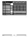
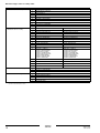
1
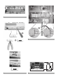
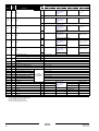
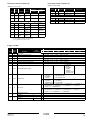
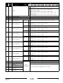
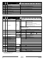
INSTALLATION MANUAL
Address card
EKAC200A
3
1
1
2
+
GND
TX+ TX-
3
29 mm
4
60 mm
2
4
20 mm
Installation manual
Address card
EKAC200A
READ THIS MANUAL ATTENTIVELY BEFORE STARTING
UP THE UNIT. DO NOT THROW IT AWAY. KEEP IT IN
YOUR FILES FOR FUTURE REFERENCE.
IMPROPER INSTALLATION OR ATTACHMENT OF
EQUIPMENT OR ACCESSORIES COULD RESULT IN
ELECTRIC SHOCK, SHORT-CIRCUIT, LEAKS, FIRE OR
OTHER DAMAGE TO EQUIPMENT. BE SURE ONLY TO
USE ACCESSORIES MADE BY DAIKIN THAT ARE
SPECIFICALLY DESIGNED FOR USE WITH THE
EQUIPMENT AND HAVE THEM INSTALLED BY A
PROFESSIONAL.
IF UNSURE OF INSTALLATION PROCEDURES OR USE,
ALWAYS CONTACT YOUR DAIKIN DEALER FOR
ADVICE AND INFORMATION.
BEFORE
YOU HANDLE THE ADDRESS CARD
If handled inappropriately, your address card may suffer damage.
Hold your address card by the edges. Never touch the rear end of the
card with your hands.
Before starting up the unit for the first time, make sure that
it has been properly installed. It is therefore necessary to
read the installation manual supplied with the unit and the
recommendations listed in "Checks before initial start-up"
carefully.
HOW
TO INSTALL THE ADDRESS CARD?
Turn the power off before installing the address card.
INTRODUCTION
Thank you for purchasing the EKAC200A address card. This address
card will enable you to communicate with your chiller through a
Building Management System or supervisory system. Please refer to
the Gateway Installation Manual for more information and a detailed
overview of how the communication works.
Install the address card
1
Remove the controller, loosen the two bolts. (See figure 1)
2
Install the address card. (See figure 2)
-
CHILLER
RANGE
-
This specific address card is designed to function with chillers of the
range
•
•
•
•
ER(*)40~60MZ, ERAP110~170MBYNN,
EUWA(*)40~200MZ, EWAP110~540MBYNN,
EUW(*)40~200M(A)X, EWWD120~540MBYNN,
EUWL(*)40~200MX, EWLD120~540MBYNN.
3
1
Install the three terminals on the main rail. (See figure 3)
- Step 1: Shift the ground terminal and endstop to the right.
- Step 2: Install the three terminals by clicking them onto the
main rail. Keep the GND, TX+ and TX– in that order.
- Step 3: Shift the ground terminal and endstop back in place
and fix them securely.
2
Plug in the wire into the address card on the controller.
3
Put the wire into the cable duct.
ADDRESS CARD KIT
The kit you have just purchased consists of:
■
1 address card (type EKAC200A) with connector
■
1 connection wire with three connected terminals
Screw connector
Put the controller back in place and fasten the two bolts. (See
figure 1)
Connect the address card to the controller
(*) = A, B, C, ...Z
YOUR
-
Step 1: Remove the cover. Use a screwdriver to unplug it.
Step 2: Remove the knock-out hole on the cover using a
wire-cutter.
Step 3: Install the address card frimly by pushing it vertically
into the controller.
Step 4: Place the cover back on the controller.
Wire
Terminal
GROUND
RX+/TX+
RX–/TX–
black
black
black
Terminal GND
Terminal TX+
Terminal TX–
DESCRIPTION
OF THE ADDRESS CARD
Measurements
See figure 4.
Connect the field rail to the gateway or to the other
address card
There are two possibilities:
■
If the chiller is the first in line or the only one to connect to a
gateway, connect it to the gateway directly.
■
If the chiller is a chiller in line and not the first one in line,
connect it to another chiller.
Read more on this in the installation manual of the gateway.
Connection to the chiller
The connection is made automatically when you insert the address
card into the PCB. The connection occurs through three pins:
Pin
Meaning
1
2
3
Ground
RX+/TX+
RX–/TX–
EKAC200A
Address card
4PW14574-1B
Installation manual
1
HOW
TO OPERATE THE ADDRESS CARD?
For more information, consult the following documents:
■
The chiller installation manual: installing BMS address card +
defining the BMS settings.
■
Installation manual of gateway.
■
Operation manual of gateway.
THE
VARIABLES DATABASE
The BMS or supervisory system and the address card communicate
through a fixed set of variables, also called address numbers.
Hereafter, you will find the information you need about the digital,
integer and analog variables that the BMS or supervisory system can
read from or write to the chiller’s address card.
NOTE
For the possible values of a direct or user parameter,
refer to the chiller operation manual.
Throughout the variables database the markers * and ** are used to
specify to what specified unit range the marked description or
comment is applicable.
■
*
■
**
■ none
for ER, EUWA, EUW and EUWL only
for ERAP, EWAD, EWWD and EWLD only
when applicable to all unit ranges
Installation manual
2
EKAC200A
Address card
4PW14574-1B
Digital variables
Comment
Address
Read/
Write
1
R
Description
*
ER
EUWA
EUW
EUWL
**
ERAP
EWAP
EWWD
EWLD
Unit status: monitoring
0 = Off, 1 = On
If 1 is written then toggle status of unit. (after this action the controller reset this parameter)
2
W
Unit status: control
3
R
Remote On/off enabled
0= No, 1 = Yes (Yes if changeable digital inputs ‘REMOTE ON/OFF" is selected)
4
R
General Alarm
0 = no alarm, 1 = alarm
5
R
General Unit alarm
0 = no alarm, 1 = alarm
6
R
General Circuit 1 alarm
0 = no alarm, 1 = alarm
7
R
General Circuit 2 alarm
0 = no alarm, 1 = alarm
8
R
—
—
9
R
General Network alarm
0 = no alarm, 1 = alarm
10
R
General Warning alarm
0 = no alarm, 1 = alarm
11
R
DI1 (0 = open, 1 = closed)
High pressure switch C1
12
R
DI2
Reverse phase protector C1
13
R
DI3
Overcurrent relay C1
14
R
DI4
Discharge thermal protector C1
15
R
DI5
Compressor thermal protector C1
16
R
DI6
Emergency stop
* Flowswitch
17
R
DI7
18
R
DI8
Changeable Input 1
19
R
DI9
Changeable Input 2
20
R
DI10
** Flowswitch
Flowswitch C1
Changeable Input 3
* Active 25% load(a)
Changeable Input 4
21
R
DI11
22
R
DI12
23
R
DI13
24
R
DI14
25
R
DI15
—
Discharge thermal protector C2(b)
26
R
DI16
—
Compressor thermal protector C2(b)
27
R
DI17
—
28
R
DI18
—
29
R
DO1
Compressor star C1
30
R
DO2
Compressor delta C1
31
R
DO3
Compressor on C1
32
R
DO4
33
R
DO5
34
R
DO6
35
R
DO7
36
R
DO8
** Changeable Input 4
* Active 40% load
** —
* Active 70% load
** —
* Active 100% load
** —
High pressure switch C2(b)
High pressure switch C2(b)
Reverse phase protector C2(b)
Reverse phase protector C2(b)
Overcurrent relay C2(b)
Overcurrent relay C2(b)
12% C1
* 40% C1
** —
* 70% C1
** —
General situation of alarm
Air/water flowcontact Pump
*
R
DO9
38
R
DO10
39
R
DO11
40
R
DO12
Evaporator heatertape
41
R
DO13
Changeable output 2
42
R
DO14
—
Compressor star C2(b)
43
R
DO15
—
Compressor delta C2(b)
44
R
DO16
—
Compressor on C2(b)
45
R
DO17
—
12% C2(b)
46
R
DO18
* —
40% C2(b)
**
*
**
*
**
Fanstep 1 of C1
25% C1(a)
37
Fanstep 2 of C1
Fanstep 3 of C1
** —
Refer to "Detail
digital variables for
EUWA units", or to
"Detail digital
variables for EWAP
units" on page 5.
—
25% C2(a)(b)
—
70% C2(b)
—
Fanstep 1 of C1
Fanstep 2 of C1
Fanstep 3 of C1
Changeable output 1
—
(a) Only available if circuit has 25% capacity step.
(b) Only available for units with 2 circuits.
EKAC200A
Address card
4PW14574-1B
Installation manual
3
Comment
Address
47
Read/
Write
R
Description
*
ER
EUWA
EUW
EUWL
**
ERAP
EWAP
EWWD
EWLD
* —
AO1(a)
Refer to "Detail
digital variables for
EUWA units" on
page 5
—
25% C1(b)
—
70% C2(c)
—
25% C2(b)
** C1 control motor upload
48
R
* —
(a)
AO2
Refer to "Detail
digital variables for
EUWA units" on
page 5
** C1 control motor download
49
R
*
AO3(a)
—
C2 control motor upload(c)
**
50
R
*
AO4(a)
—
51
R
AO5(a)
—
**
52
R
*
AO6(a)
53
R
—
Refer to "Detail
digital variables for
EUWA units" on
page 5
—
Refer to "Detail
digital variables for
EUWA units" on
page 5
Fanstep 2 of C2(c)
—
—
—
Fanstep 3 of C2(c)
—
** —
25% Capacity Coils C2(c)
* 0 = no, 1 = yes
R
55
R
EEV1(d)
0 = no, 1 = yes
56
R
EEV2(c)(d)
0 = no, 1 = yes
57
R
High pressure setback active C1
0 = no, 1 = yes
58
R
High pressure setback active C2(c)
0 = no, 1 = yes
59
R
Low pressure bypass C1 active
0 = no, 1 = yes
60
R
Low pressure bypass C2 active(c)
0 = no, 1 = yes
61
R
Maximum fan output C1 active(e)
62
R
Maximum fan output C2 active(c)(e)
63
R
Freeze up prevention C1 active
64
R
Freeze up prevention C2 active(c)
65
R
Low noise status
66
R
A11P:DO1
** —
67
R
A11P:DO2
** —
68
R
A11P:DO3
69
R
A11P:DO4
70
R
71
72
73
—
Fanstep 1 of C2(c)
* 0 = no, 1 = yes
54
(a)
(b)
(c)
(d)
(e)
** —
only if
software version
≥V3.0M6
0 = no, 1 = yes
0 = no, 1 = yes
0 = no, 1 = yes
0 = no, 1 = yes
0 = no, 1 = yes
—
Fanstep 1 of C2
—
Fanstep 2 of C2
** —
Refer to "Detail
digital variables for
EUWA units" on
page 5.
—
Fanstep 3 of C2
** —
—
—
—
A11P:DI1
** —
—
Flowswitch C2(c)
R
A11P:DI2
** —
—
—
—
R
A11P:DI3
** —
—
—
—
R
A11P:DI4
** —
—
—
—
Analog output used as digital output.
Only available if circuit has 25% capacity step.
Only available for units with 2 circuits.
EEV = Electronic Expansion Valve.
Only available if circuit has inverter fans.
Installation manual
4
—
—
—
**
25% Capacity Coils C1
Refer to "Detail
digital variables for
EUWA units" on
page 5.
C2 control motor download(c)
**
*
Refer to "Detail
digital variables for
EUWA units" on
page 5.
EKAC200A
Address card
4PW14574-1B
Detail digital variables for EUWA units
Detail digital variables for EWAP units
(Address 37~39, 47~52)
(Adress 37~39, 66~68)
Fans = inverter
Address
Read/
Write
37
R
Description
DO9
Fans = non
inverter
Units with 1
circuit
Units with 2
circuits
Fanstep 1
of C1
Fanstep
on-off of C1
25% C1
38
R
DO10
Fanstep 2
of C1
—
25% C2
39
R
DO11
Fanstep 3
of C1
—
70% C2
47
R
AO1(a)
25% C1(b)
25% C1(b)
Fanstep
on-off of C1
48
R
AO2(a)
70% C2(c)
—
—
R
(a)
25% C2(b)(c) —
—
(a)
—
Fanstep
on-off of C2
49
AO3
50
R
AO4
Fanstep 1
of C2(c)
51
R
AO5(a)
Fanstep 2
of C2(c)
—
—
52
R
AO6(a)
Fanstep 3
of C2(c)
—
—
Address
Read/
Write
37
R
DO9
Fanstep 1 of C1
Fanstep on-off of C1
38
R
DO10
Fanstep 2 of C1
—
39
R
DO11
Fanstep 3 of C1
—
66
R
A11P:DO1 Fanstep 1 of C2
Fanstep on-off of C2
67
R
A11P:DO2 Fanstep 2 of C2
—
68
R
A11P:DO3 Fanstep 3 of C2
—
Description
Fans = non inverter
Fans = inverter
(a) Analog output used as digital output
(b) Only available if circuit has 25% capacity step
(c) Only available for units with 2 circuits
Integer variables
Comment
ER
EUWA
EUW
EUWL
**
ERAP
EWAP
EWWD
EWLD
Address
Read/
Write
1
R
BMS allowed
2
R
Malfunction code of unit safety
0 = no safety, 1 = "F0", 2 = "AE", … (refer to overview)
3
R
Malfunction code of C1 safety
0 = no safety, 1 = "U1", 2 = "E3", … (refer to overview)
4
R
Malfunction code of C2 safety
0 = no safety, 1 = "U1", 2 = "E3", … (refer to overview)
5
R
—
0 = no safety, 1 = "U1", 2 = "E3", … (refer to overview)
6
R
Malfunction code of network safety
0 = no safety, 1 = "U4", 2 = "CA", … (refer to overview)
7
R
Malfunction code of warning
0 = no safety, 1 = "AE", 2 = "A9", … (refer to overview)
8
R/W
Unit of
measurement
*
Description
0 = N, 1 = Y
Cooling/Heating mode setting
*
9
R/W
Running mode
**
10
R
11
R
12
R
EKAC200A
Address card
4PW14574-1B
—
0 = "MANUAL
CONTROL"
3 = "EXTERNAL
THERM."
0 = "MANUAL CONTROL"
1 = "INL WATER STEP"
2 = "OUTL WATER STEP"
0 = "MANUAL CONTROL"
0 = "MANUAL
CONTROL"
1 = "INL WATER"
4 = "THERMOSTAT" 2 = "OUTL WATER"
0 = "MANUAL MODE", 1 = "INLSETP1 E: ", 2 = "INLSETP2 E: ", 3 = "OUTSETP1 E: ",
** 4 = "OUTSETP2 E: ", 5 = "INLSETP1 C: ", 6 = "INLSETP2 C: ", 7 = "SP1E: C:",
8 = "SP2E: C:", 10 = "SETPOINT1:", 11 = "SETPOINT2:"
Actual thermostat step
*
%
Maximum number of thermostat step
Capacity C2
—
0 = "MANUAL MODE", 1 = "INLSETP1 E: ", 2 = "INLSETP2 E: ", 3 = "OUTSETP1 E: ",
* 4 = "OUTSETP2 E: ", 5 = "INLSETP1 C: ", 6 = "INLSETP2 C: ", 7 = "SP1E: C:",
8 = "SP2E: C:", 9 = "THERMOSTAT"
Active mode
Capacity C1
0 = "COOLING
(EVAP)"
1 = "HEATING
(COND)"
—
2 = "DOUBLE
THERM" (only if
no remote C/H)
%
**
*
**
Installation manual
5
Comment
Address
Read/
Write
Unit of
measurement
Description
R
Status of circuit 1
14
R
Status of circuit 2
15
R
Running hours compressor 1
(Higher part)
hx1000
16
R
Running hours compressor 1
(Lower part)
h
17
R
Running hours compressor 2
(Higher part)(a)
hx1000
18
R
Running hours compressor 2
(Lower part)(a)
h
19
R
Actual fan1 step
20
R
Actual fan2 step(a)
R/W
R/W
24
R/W
Manual setting of fans C2
25
R/W
Loadup time in inlet control
26
R/W
Loaddown time in inlet control
27
R/W
Loadup time in outlet control
28
R/W
Loaddown time in outlet control
29
R/W
30
R
31
R/W
32
EWAP
EWWD
EWLD
*
If 25% = Yes
0 = "0%", 1 = "25%", 2 = "40%", 3= "70%", 4 = "100%"
If 25% = No
0 = "0%", 1 = "40%", 2 = "70%", 3 = "100%"
** 0, 30~100
*
%
Manual setting of fans C1
EUWL
ERAP
If fans = none inverter
0 = "OFF", 1 = "LOW", 2 = "MED", 3 = "HIGH"
if fans = inverter
then value = Fan onoff + Fan inverter
example: 0% = (Fan onoff = off) + (Fan inverter = 00 Hz)
example: 100% = (Fan onoff = on) + (Fan inverter = 50 Hz)
Manual setting
of compressor 2(a)
R/W
EUW
**
Running hours = Higher part x 1000 + Lower part
Manual setting
of compressor 1
23
EUWA
0 = "OFF-CAN STARTUP", 1 = "OFF-TIMER BUSY", 2 = "ON – % STAR",
3 = "ON – % DELTA ", 8 = "ON – % (LIMIT)", 12 = "OFF – % (LIMIT)",
**
13 = "OFF-FREEZE UP DIS", 14 = "OFF-SAFETY ACTIVE" 15 = "ON – % SHEAT REC",
16 = "ON – % DHEAT REC",
%
22
ER
0 = "OFF-CAN STARTUP", 1 = "OFF-TIMER BUSY", 2 = "ON – 12% STAR",
3 = "ON – 12% DELTA ", 4 = "ON – 25% DELTA", 5 = "ON – 40% DELTA",
6 = "ON – 70% DELTA", 7 = "ON – 100% DELTA", 8 = "ON – 25% (LIMIT)",
* 9 = "ON – 40% (LIMIT)", 10 = "ON – 70% (LIMIT)", 11 = "ON – 100% (LIMIT)",
12 = "OFF – 0% (LIMIT)", 13 = "OFF-FREEZE UP DIS", 14 = "OFF-SAFETY ACTIVE"
15 = "ON – 12% SHEAT REC", 16 = "ON – 12% DHEAT REC", 17 = "ON – 25% HEAT REC",
18 = "ON – 40% HEAT REC", 19 = "ON – 70% HEAT REC", 20 = "ON – 100% HEAT REC"
13
21
*
If 25% = Yes
0 = "0%", 1 = "25%", 2 = "40%", 3= "70%", 4 = "100%"
If 25% = No
0 = "0%", 1 = "40%", 2 = "70%", 3 = "100%"
** 0, 30~100
If fans = none inverter
0 = "OFF", 1 = "LOW", 2 = "MED", 3 = "HIGH"
if fans = inverter
then value = Fan onoff + Fan inverter
example: 0% = (Fan onoff = off) + (Fan inverter = 00 Hz)
example: 100% = (Fan onoff = on) + (Fan inverter = 50 Hz)
s
sx 12
s
sx 12
s
sx 12
s
sx 12
*
**
*
**
*
**
*
**
DICN: Nr Of Slaves(b)
DICN: Master or slave(b)
0 = Master, 1 = Slave1, 2 = Slave2, 3 = Slave3
DICN: Mode(b)
0 = "NORMAL",1 = "STANDBY", 2 = "DISCONN. ON/OFF"
R
DICN: Status of master(b)
0 = "NORMAL",1 = "STANDBY", 2 = "DISCONN.", 3 = "SAFETY"
33
R
DICN: Status of S1(b)
0 = "NORMAL",1 = "STANDBY", 2 = "DISCONN.", 3 = "SAFETY"
34
R
DICN: Status of S2(b)
0 = "NORMAL",1 = "STANDBY", 2 = "DISCONN.", 3 = "SAFETY"
35
R
DICN: Status of S3(b)
0 = "NORMAL",1 = "STANDBY", 2 = "DISCONN.", 3 = "SAFETY"
36
R
EEV1 Status
0 = "NO WARNINGS",1 = "VALVE OPEN", 2 = "BATTERY CHARGED",
3 = "EEPROM ERR."
37
R
EEV2 Status(c)
0 = "NO WARNINGS",1 = "VALVE OPEN", 2 = "BATTERY CHARGED",
3 = "EEPROM ERR."
38
R
EEV1 Battery Status(c)
*
0 = "DISCONNECTED",1 = "HIGH INT.RES.", 2 = "NOT RECHARGE", 3 = "DOWN",
4 = "OK"
39
R
EEV2 Battery Status(c)
*
0 = "DISCONNECTED",1 = "HIGH INT.RES.", 2 = "NOT RECHARGE", 3 = "DOWN",
4 = "OK"
40
R
Unittype1
0 = "AW", 1 = "WW"
41
R
Unittype2
0 = "CO", 1 = "HO", 2 = "HR", 3 = "RH", 4 = "HP", 5 = "RC", 6 = "CA"
(c)
(a) Only available for units with 2 circuits
(b) DICN = Daikin Integrated Chiller Network
(c) EEV = Electronic Expansion Valve
Installation manual
6
EKAC200A
Address card
4PW14574-1B
Comment
Address
Read/
Write
Description
Unit of
measurement
*
ER
EUWA
EUW
EUWL
**
ERAP
EWAP
EWWD
EWLD
0 = "40",1 = "50", 2 = "60", 3 = "80", 4 = "100", 5 = "120", 6 = "140", 7 = "160",
*
8 = "180", 9 = "200"
42
R
Unittype3
43
R
Number of circuits
44
R
Number of Evaporators
45
R
Refrigerant
46
47
R
R/W
Minimum outlet water
ERAP: 0 = "110", 1 = "140", 2 = "170"
EWAP: 0 = "110", 1 = "140", 2 = "160", 3 = "200", 4 = "280", 5 = "340",
7 = "400", 8 = "460", 9 = "540"
EWAD: 0 = "120", 1 = "150", 2 = "170", 3 = "240", 4 = "300", 5 = "340"
**
EWWD: 0 = "120", 2 = "180", 3 = "240", 4 = "280", 5 = "360", 6 = "440", 7 = "500",
8 = "520", 9 = "540"
EWLD: 0 = "120", 2 = "170", 3 = "240", 4 = "260", 5 = "340", 6 = "400", 7 = "480",
8 = "500", 9 = "540"
0 = "R134a", 1 = "R407C"
only if
software version
<V3.0M6
*
Limitation 1 setting of C1
%
48
R/W
R/W
*
Limitation 1 setting of C2(a)
R/W
If 25% = Yes
0 = "0%", 1 = "25%", 2 = "40%", 3 = "70%", 4 = "100%"
*
If 25% = No
0 = "0%", 1 = "40%", 2 = "70%", 3 = "100%"
Limitation 2 setting of C1
** 0, 30~100
*
Limitation 2 setting of C2(a)
%
51
R/W
R/W
*
Limitation 3 setting of C1
R/W
If 25% = Yes
0 = "0%", 1 = "25%", 2 = "40%", 3 = "70%", 4 = "100%"
If 25% = No
0 = "0%", 1 = "40%", 2 = "70%", 3 = "100%"
** 0, 30~100
*
Limitation 3 setting of C2(a)
%
53
If 25% = Yes
0 = "0%", 1 = "25%", 2 = "40%", 3 = "70%", 4 = "100%"
If 25% = No
0 = "0%", 1 = "40%", 2 = "70%", 3 = "100%"
** 0, 30~100
%
52
If 25% = Yes
0 = "0%", 1 = "25%", 2 = "40%", 3 = "70%", 4 = "100%"
If 25% = No
0 = "0%", 1 = "40%", 2 = "70%", 3 = "100%"
** 0, 30~100
%
50
If 25% = Yes
0 = "0%", 1 = "25%", 2 = "40%", 3 = "70%", 4 = "100%"
If 25% = No
0 = "0%", 1 = "40%", 2 = "70%", 3 = "100%"
** 0, 30~100
%
49
* 0 = "8°C", 1 = "5°C", 2 = "4°C", 3 = "2°C", 4 = "0°C", 5 = "–5°C", 6 = "–10°C"
If 25% = Yes
0 = "0%", 1 = "25%", 2 = "40%", 3 = "70%", 4 = "100%"
If 25% = No
0 = "0%", 1 = "40%", 2 = "70%", 3 = "100%"
** 0, 30~100
*
Limitation 4 setting of C1
%
If 25% = Yes
0 = "0%", 1 = "25%", 2 = "40%", 3 = "70%", 4 = "100%"
If 25% = No
0 = "0%", 1 = "40%", 2 = "70%", 3 = "100%"
** 0, 30~100
*
If 25% = Yes
0 = "0%", 1 = "25%", 2 = "40%", 3 = "70%", 4 = "100%"
If 25% = No
0 = "0%", 1 = "40%", 2 = "70%", 3 = "100%"
54
R/W
Limitation 4 setting of C2(a)
55
R/W
Limitation mode
0 = "REMOTE DIG INP.", 1 = "SCHEDULE TIMER", 2 = "LIM1", 3 = "NOT ACTIVE"
56
R/W
Low noise mode
0 = "CH.DI", 1 = "SCH.T", 2 = "YES", 3 = "NO"
57
R/W
Number of compressor 1 starts
(Higher part)
58
R/W
Number of compressor 1 starts
(Lower part)
59
R/W
Number of compressor 2 starts
(Higher part)(a)
60
R/W
Number of compressor 2 starts
(Lower part)(a)
%
** 0, 30~100
only if
software version
≥V3.0M6
Number of compressor starts = Higher part x 1000 + Lower part
(a) Only available for unit with 2 circuits
EKAC200A
Address card
4PW14574-1B
Installation manual
7
Comment
ER
EUWA
EUW
EUWL
**
ERAP
EWAP
EWWD
EWLD
Address
Read/
Write
101
R
Software code
1 = "FLDKNMCH0A", 2 = "FLDKNMCHLA"
102
R
Software version high
Software version = V SoftVersionHigh.SoftVersionLow
103
R
Software version low
Software version = V SoftVersionHigh.SoftVersionLow
104
R
Boot version high
Bootversion = V BootVersionHigh.BootVersionLow
105
R
Boot version low
Bootversion = V BootVersionHigh.BootVersionLow
106
R
Bios version high
Bios version = V BiosVersionHigh.BiosVersionLow
107
R
Bios version low
Bios version = V BiosVersionHigh.BiosVersionLow
108
R
EEV1 Software version(a)
109
R
EEV1 Hardware version(a)
110
R
EEV2 Software version(a)
111
R
EEV2 Hardware version(a)
Description
Unit of
measurement
*
(a) EEV = Electronic Expansion Valve
Analog variables
Comment
ER
EUWA
EUW
EUWL
**
ERAP
EWAP
EWWD
EWLD
Address
Read/
Write
1
R
Analog input 1
bar x 1/10
High pressure C1
2
R
Analog input 2 (or AI of EEV(a))
bar x 1/10
Low pressure C1
Description
Unit of
measurement
*
* —
3
R
Analog input 3
°C x 1/10
or mV
or V x 1/10
or mA
Changeable AI1
Possible settings of changeable AI1:
- Setpoint signal (mV/V/mA)
**
- Heat recovery condensor inlet water(c)
—
4
R
Analog input 4
5
R
Analog input 5
6
R
Analog input 6
°C x 1/10
—
°C x 1/10
* —
°C x 1/10
Ambient
* —
Evaporator outlet water sensor DICN (optional on Master)
Evaporator Inlet water sensor
Evaporator mixed outlet temperature
Evaporator mixed outlet temperature
Condenser Inlet
water sensor
Ambient
High pressure C2
R
Analog input 7
Ω x 1/10
or bar x 1/10
8
R
Analog input 8 (or AI of EEV(a))
bar x 1/10
—
Low pressure C2(d)
9
R
Analog input 9
—
Evaporator Outlet water sensor C1
10
R
Analog input 10
—
Evaporator Outlet water sensor C2(d)
11
R
AI1 converted in °C
12
R
AI2 converted in °C (or AI of
EEV(a))
13
R
AI7 converted in °C
14
R
AI8 converted in °C (or AI of
EEV(a))
15
R
16
R
17
R
18
R/W
19
R/W
21
(a)
(b)
(c)
(d)
R/W
R/W
C1 capacity
**
feedback
Ambient
(d)
7
20
1 circ units: C1 capacity feedback
2 circ units: High pressure C2(d)
°C x 1/10
Active inlet evaporator setpoint
Active outlet evaporator setpoint
—
*
** Active setpoint
Active outlet evaporator setpoint
Active inlet condensor setpoint
Inlet setpoint 1 Evaporator
Inlet setpoint 2 Evaporator
Outlet setpoint 1 Evaporator
—
Outlet setpoint 2 Evaporator
—
*
** Setpoint 1
Outlet setpoint 1 evaporator
*
** Setpoint 2
Outlet setpoint 2 evaporator
EEV = Electronic Expansion Valve
DICN = Daikin Integrated Chiller Network
Only for heat recovery units
Only available for units with 2 circuits
Installation manual
8
** Thermostat sensor
°C x 1/10
bar x 1/10
If software version < V3.0M6
Evaporator Outlet water sensor DICN(b) (optional on Master)
If software version ≥ V3.0M6
Changeable Analog input 1
Possible settings of changeable Analog input 1:
- Evaporator outlet water sensor DICN(b) (optional on Master)
- Setpoint signal (mV/V/mA)
- Heat recovery condensor inlet water(c)
EKAC200A
Address card
4PW14574-1B
Comment
Address
Read/
Write
22
R/W
Inlet setpoint 1 Condensor
23
R/W
Inlet setpoint 2 Condensor
24
R/W
Step length inlet control
25
R/W
Step length outlet control
26
R/W
27
R
28
R
Description
Unit of
measurement
ER
EUWA
EUW
EUWL
**
ERAP
EWAP
EWWD
EWLD
Step difference outlet
Analog Output 1
Analog Output 2
V x 1/10
V x 1/10
29
R
Analog Output 3
V x 1/10
30
R
Analog Output 4
V x 1/10
31
R
Analog Output 5
V x 1/10
32
R
Analog Output 6
V x 1/10
33
R
Minimum outlet water
R
Heat recovery inlet
setpoint condensor(c)
34
*
—
* —
** —
—
—
—
Fan inverter C1(a)
—
—
—
—
—
Fan inverter C2(a)(b)
—
—
** —
—
—
—
—
—
—
—
* —
—
—
—
* —
** —
* —
Fan inverter C1(a)
—
—
—
**
Fan inverter C2(a)(b)
—
—
** —
2 circuit units: C1 capacity feedback(b)
** —
2 circuit units: C2 capacity feedback(b)
°C x 1/10
Heat recovery inlet
difference condensor(c)
35
R/W
36
R
A11P: AI1
37
R
A11P: AI2
38
R
A11P: AI3
** —
39
R
A11P: AI4
** —
Ω x 1/10
(a) Only available if circuit has inverter fans
(b) Only available for units with 2 circuits
(c) Only for heat recovery units
EKAC200A
Address card
4PW14574-1B
Installation manual
9
Overview integer values of safety codes
Integer adress
2: Malfunction code of unit safety
3: Malfunction code of C1 safety
4: Malfunction code of C2 safety
6: Malfunction code of network safety
7: Malfunction code of warning
Value
Message safety menu
1
"0F0:EMERGENCY STOP"
2
"0AE:FLOW HAS STOPPED"
3
"0A4:FREEZE UP"
4
"0C9:INL E SENSOR ERR"
5
"0CA:OUT E SENSOR ERR"
6
"0H9:AMB T SENSOR ERR"
7
"0HC:INL C SENSOR ERR"
8
"0HC:HR INL C SENSOR ERR"
9(a)
"0U4: PCB EXP COMM.ERR"
10(a)
"0CJ: THERM SENSOR ERR"
Circuit safety 1
Circuit safety 2
1
"1U1:REV PHASE PROT"
"2U1:REV PHASE PROT"
2
"1E3:HIGH PRESSURE SW"
"2E3:HIGH PRESSURE SW"
3
"1E5:COMPR THERM PROT"
"2E5:COMPR THERM PROT"
4
"1E6:OVERCURRENT"
"2E6:OVERCURRENT"
5
"1F3:DISCH THERM PROT"
"2F3:DISCH THERM PROT"
6
"1E4:LOW PRESSURE"
"2E4:LOW PRESSURE"
7
"1A4:FREEZE UP"
"2A4:FREEZE UP"
8
"1JA:HP TRANSM ERR"
"2JA:HP TRANSM ERR"
9
"1JC:LP TRANSM ERR"
"2JC:LP TRANSM ERR"
10
"1CA:OUT E SENSOR ERR"
"2CA:OUT E SENSOR ERR"
11
"(1A9: EEV *** ERR)"(b)
"1A9:EEV DRIVER ERROR"
"1A9:EEV NOT CLOSED"
"1A9:EEV SUPERHEAT ER"
"1A9:EEV HIGH PRESSURE"
"1A9:EEV EEPROM ERR"
"1A9:EEV ST.MOTOR ERR"
"1A9:EEV PROBE ERR"
"(2A9: EEV *** ERR)"(b)
"2A9:EEV DRIVER ERROR"
"2A9:EEV NOT CLOSED"
"2A9:EEV SUPERHEAT ER"
"2A9:EEV HIGH PRESSURE"
"2A9:EEV EEPROM ERR"
"2A9:EEV ST.MOTOR ERR"
"2A9:EEV PROBE ERR"
12(a)
"193: CONTR. MOTOR ERR"
"293: CONTR. MOTOR ERR"
(a)
13
"194: CONTR. MOTOR REV"
"294: CONTR. MOTOR REV"
14(a)
"1AE: FLOW HAS STOPPED"
"2AE: FLOW HAS STOPPED"
15(a)
"153: FAN INV ERR.
"253: FAN INV ERR."
1
"0U4:PCB COMM.PROBLEM"
2
"0CA:OUT E SENSOR ERR"
3
"0C9:INL E SENSOR ERR"
1
"0AE:FLOW HAS STOPPED"
2
"1A9:EEV BATTERY ERR"(b)
3
"2A9:EEV BATTERY ERR"(b)
4
"153:FAN INV ERR"
5
"253:FAN INV ERR"
(a) Only for ERAP, EWAP, EWWD, EWLD.
(b) EEV = Electronic Expansion Valve
Installation manual
10
EKAC200A
Address card
4PW14574-1B
NOTES
Zandvoordestraat 300, B-8400 Oostende, Belgium
4PW14574-1B