1
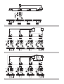
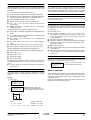
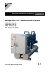
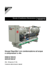
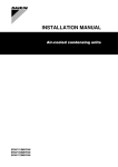
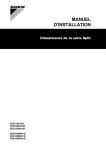
INSTALLATION MANUAL Packaged water-cooled water chillers EWWD120MBYNN EWWD180MBYNN EWWD240MBYNN EWWD280MBYNN EWWD360MBYNN EWWD440MBYNN EWWD500MBYNN EWWD520MBYNN EWWD540MBYNN 1 M1P LOAD SLAVE 3 SLAVE 2 N L1 F4 SLAVE 1 L2 R8T L3 F2 F1 MASTER F3 230 V ~ 24 V ~ K1P F5 M1P K1P 73 74 75 76 77 78 79 73 74 75 76 77 78 79 73 74 75 76 77 78 79 73 74 75 76 77 78 79 S10S (M) S6S (S3) K1P K1P SLAVE 3 K1P SLAVE 2 S6S (M) K1P SLAVE 1 MASTER 1 2 LOAD R8T M4P M3P M2P M1P SLAVE 3 SLAVE 2 SLAVE 1 MASTER SLAVE 3 N L1 F13 SLAVE 2 L2 F1 L3 F2 230 V ~ 24 V ~ N F15 F3 K4P F14 L1 SLAVE 1 L2 F4 L3 F5 230 V ~ 24 V ~ N M4P F17 F6 K3P F16 L1 MASTER L2 F7 L3 F8 230 V ~ 24 V ~ N M3P F19 F9 K2P F18 L1 L2 F10 L3 F11 230 V ~ 24 V ~ F12 K1P F20 M2P M1P S1S K4P 73 74 K3P 75 76 77 78 79 73 74 K2P 75 76 77 78 79 73 74 K1P 75 76 77 78 79 73 74 75 76 77 78 79 S10S (M) S6S (S3) K4P K3P K2P S6S (M) K1P 2 3 Y1S LOAD R9T M5P M4P M3P M2P M1P SLAVE 3 SLAVE 2 SLAVE 1 MASTER SLAVE 3 N L1 F13 230V ~ 24V ~ SLAVE 2 L2 F1 L3 F2 N F3 K4P F14 L1 F15 230V ~ 24V ~ SLAVE 1 L2 F4 L3 F5 N F6 K3P F16 M4P L1 F17 230V ~ 24V ~ MASTER L2 F7 L3 F8 N F9 K2P F18 M3P L1 F19 230V ~ 24V ~ L2 F10 L3 F11 F12 K1P F20 M2P M1P S1S K4P 73 74 75 K3P 76 77 78 79 73 74 75 K2P 76 77 78 79 73 74 75 K1P 76 77 78 79 73 74 75 76 77 78 79 S10S (M) K4P 3 S6S (S3) K3P K2P K1P S6S (M) 10 11 12 13 14 15 16 17 18 CE - ERKLÆRING OM-SAMSVAR CE - ILMOITUS-YHDENMUKAISUUDESTA CE - PROHLÁŠENÍ-O-SHODĚ 19 20 21 22 23 24 25 CE - IZJAVA O SKLADNOSTI CE - VASTAVUSDEKLARATSIOON CE - ДЕКЛАРАЦИЯ-ЗА-СЪОТВЕТСТВИЕ 19 ob upoštevanju določb: 20 vastavalt nõuetele: 21 следвайки клаузите на: 22 laikantis nuostatų, pateikiamų: 23 ievērojot prasības, kas noteiktas: 24 održiavajúc ustanovenia: 25 bunun koşullarına uygun olarak: 06 * delineato nel File Tecnico di Costruzione <A> e giudicato positivamente da <B> secondo il Certificato <C>. ** delineato nel File Tecnico di Costruzione <D> e giudicato positivamente da <E> (Modulo <F> applicato) secondo il Certificato <G>. 07 * fiˆ˜ ÚÔÛ‰ÈÔÚ›˙ÂÙ·È ÛÙÔ ∞Ú¯Â›Ô ∆¯ÓÈ΋˜ ∫·Ù·Û΢‹˜ <A> Î·È ÎÚ›ÓÂÙ·È ıÂÙÈο ·fi ÙÔ <B> Û‡Ìʈӷ Ì ÙÔ ¶ÈÛÙÔÔÈËÙÈÎfi <C>. ** fiˆ˜ ÚÔÛ‰ÈÔÚ›˙ÂÙ·È ÛÙÔ ∞Ú¯Â›Ô ∆¯ÓÈ΋˜ ∫·Ù·Û΢‹˜ <D> Î·È ÎÚ›ÓÂÙ·È ıÂÙÈο ·fi ÙÔ <E> (ÃÚËÛÈÌÔÔÈÔ‡ÌÂÓË ˘ÔÌÔÓ¿‰· <F>) Û‡Ìʈӷ Ì ÙÔ ¶ÈÛÙÔÔÈËÙÈÎfi <G>. 08 * tal como estabelecido no Ficheiro Técnico de Construção <A> e com o parecer positivo de <B> de acordo com o Certificado <C>. ** tal como estabelecido no Ficheiro Técnico de Construção <D> e com o parecer positivo de <E> (Módulo aplicado <F>) de acordo com o Certificado <G>. 09 * как указано в Досье технического толкования <A> и в соответствии с положительным решением <B> согласно Свидетельству <C>. ** как указано в Досье технического толкования <D> и в соответствии с положительным решением <E> (Прикладной модуль <F>) согласно Свидетельству <G>. 10 * som anført i den Tekniske Konstruktionsfil <A> og positivt vurderet af <B> i henhold til Certifikat <C>. ** som anført i den Tekniske Konstruktionsfil <D> og positivt vurderet af <E> (Anvendt modul <F>) i henhold til Certifikat <G>. 10 under iagttagelse af bestemmelserne i: 11 enligt villkoren i: 12 gitt i henhold til bestemmelsene i: 13 noudattaen määräyksiä: 14 za dodržení ustanovení předpisu: 15 prema odredbama: 16 követi a(z): 17 zgodnie z postanowieniami Dyrektyw: 18 în urma prevederilor: 01 * as set out in the Technical Construction File <A> and judged positively by <B> according to the Certificate <C>. ** as set out in the Technical Construction File <D> and judged positively by <E> (Applied module <F>) according to the Certificate <G>. 02 * wie in der Technischen Konstruktionsakte <A> aufgeführt und von <B> positiv ausgezeichnet gemäß Zertifikat <C>. ** wie in der Technischen Konstruktionsakte <D> aufgeführt und von <E> (Angewandtes Modul <F>) positiv ausgezeichnet gemäß Zertifikat <G>. 03 * tel que stipulé dans le Fichier de Construction Technique <A> et jugé positivement par <B> conformément au Certificat <C>. ** tel que stipulé dans le Fichier de Construction Technique <D> et jugé positivement par <E> (Module appliqué <F>) conformément au Certificat <G>. 04 * zoals vermeld in het Technisch Constructiedossier <A> en in orde bevonden door <B> overeenkomstig Certificaat <C>. ** zoals vermeld in het Technisch Constructiedossier <D> en in orde bevonden door <E> (Toegepaste module <F>) overeenkomstig Certificaat <G>. 05 * tal como se expone en el Archivo de Construcción Técnica <A> y juzgado positivamente por <B> según el Certificado <C>. ** tal como se expone en el Archivo de Construcción Técnica <D> y juzgado positivamente por <E> (Modulo aplicado <F>) según el Certificado <G>. 01 following the provisions of: 02 gemäß den Vorschriften der: 03 conformément aux stipulations des: 04 overeenkomstig de bepalingen van: 05 siguiendo las disposiciones de: 06 secondo le prescrizioni per: 07 Ì ًÚËÛË Ùˆv ‰È·Ù¿Íˆv Ùˆv: 08 de acordo com o previsto em: 09 в соответствии с положениями: EN60335-2-40, 01 are in conformity with the following standard(s) or other normative document(s), provided that these are used in accordance with our instructions: 02 der/den folgenden Norm(en) oder einem anderen Normdokument oder -dokumenten entspricht/entsprechen, unter der Voraussetzung, daß sie gemäß unseren Anweisungen eingesetzt werden: 03 sont conformes à la/aux norme(s) ou autre(s) document(s) normatif(s), pour autant qu'ils soient utilisés conformément à nos instructions: 04 conform de volgende norm(en) of één of meer andere bindende documenten zijn, op voorwaarde dat ze worden gebruikt overeenkomstig onze instructies: 05 están en conformidad con la(s) siguiente(s) norma(s) u otro(s) documento(s) normativo(s), siempre que sean utilizados de acuerdo con nuestras instrucciones: 06 sono conformi al(i) seguente(i) standard(s) o altro(i) documento(i) a carattere normativo, a patto che vengano usati in conformità alle nostre istruzioni: 07 Â›Ó·È Û‡Ìʈӷ Ì ÙÔ(·) ·ÎfiÏÔ˘ıÔ(·) ÚfiÙ˘Ô(·) ‹ ¿ÏÏÔ ¤ÁÁÚ·ÊÔ(·) ηÓÔÓÈÛÌÒÓ, ˘fi ÙËÓ ÚÔ¸fiıÂÛË fiÙÈ ¯ÚËÛÈÌÔÔÈÔ‡ÓÙ·È Û‡Ìʈӷ Ì ÙȘ Ô‰ËÁ›Â˜ Ì·˜: *= , -, 1, 2, 3, ..., 9, A, B, C, ..., Z Jiro Tomita Director Quality Assurance Ostend, 1st of August 2005 11 * utrustningen är utförd i enlighet med den Tekniska Konstruktionsfilen <A> som positivt intygas av <B> vilket också framgår av Certifikat <C>. ** i enlighet med den Tekniska Konstruktionsfilen <D> som positivt intygats av <E> (Fastsatt modul <F>) vilket också framgår av Certifikat <G>. 12 * som det fremkommer i den Tekniske Konstruksjonsfilen <A> og gjennom positiv bedømmelse av <B> ifølge Sertifikat <C>. ** som det fremkommer i den Tekniske Konstruksjonsfilen <D> og gjennom positiv bedømmelse av <E> (Anvendt modul <F>) ifølge Sertifikat <G>. 13 * jotka on esitetty Teknisessä Asiakirjassa <A> ja jotka <B> on hyväksynyt Sertifikaatin <C> mukaisesti. ** jotka on esitetty Teknisessä Asiakirjassa <D> ja jotka <E> on hyväksynyt (Sovellettu moduli <F>) Sertifikaatin <G> mukaisesti. 14 * jak bylo uvedeno v souboru technické konstrukce <A> a pozitivně zjištěno <B> v souladu s osvědčením <C>. ** jak bylo uvedeno v souboru technické konstrukce <D> a pozitivně zjištěno <E> (použitý modul <F>) v souladu s osvědčením <G>. 15 * kako je izloženo u Datoteci o tehničkoj konstrukciji <A> i pozitivno ocijenjeno od strane <B> prema Certifikatu <C>. ** kako je izloženo u Datoteci o tehničkoj konstrukciji <D> i pozitivno ocijenjeno od strane <E> (Primijenjen modul <F>) prema Certifikatu <G>. 16 * a(z) <A> műszaki konstrukciós dokumentáció alapján, a(z) <B> igazolta a megfelelést a(z) <C> tanúsítvány szerint. ** a(z) <D> műszaki konstrukciós dokumentáció alapján, a(z) <E> igazolta a megfelelést (alkalmazott modul: <F>), a(z) <G> tanúsítvány szerint. 17 * zgodnie z archiwalną dokumentacją konstrukcyjną <A>, pozytywną opinią <B> i Świadectwem <C>. ** zgodnie z archiwalną dokumentacją konstrukcyjną <D> i pozytywną opinią <E> (Zastosowany moduł <F>) zgodnie ze Świadectwem <G>. 18 * conform celor stabilite în Dosarul tehnic de construcţie <A> şi apreciate pozitiv de <B> în conformitate cu Certificatul <C>. ** conform celor stabilite în Dosarul tehnic de construcţie <D> şi apreciate pozitiv de <E> (Modul aplicat <F>) în conformitate cu Certificatul <G>. 19 * kot je določeno v tehnični mapi <A> in odobreno s strani <B> v skladu s certifikatom <C>. ** kot je določeno v tehnični mapi <D> in odobreno s strani <E> (Uporabljen modul <F>) v skladu s certifikatom <G>. 20 * nagu on näidatud tehnilises dokumentatsioonis <A> ja heaks kiidetud <B> järgi vastavalt sertifikaadile <C>. ** nagu on näidatud tehnilises dokumentatsioonis <D> ja heaks kiidetud <E> järgi (lisamoodul <F>) vastavalt sertifikaadile <G>. Low Voltage 73/23/EEC Machinery Safety 98/37/EEC Electromagnetic Compatibility 89/336/EEC * Pressure Equipment 97/23/EEC ** DAIKIN.TCF.013 KEMA 71801-KRQ/ECM97-4240 Daikin.TCFP.002 AIB Vinçotte (NB0026) H 52846/01/12/01 <A> <B> <C> <D> <E> <F> <G> 19 Direktive z vsemi spremembami. 20 Direktiivid koos muudatustega. 21 Директиви, с техните изменения. 22 Direktyvose su papildymais. 23 Direktīvās un to papildinājumos. 24 Smernice, v platnom znení. 25 Değiştirilmiş halleriyle Yönetmelikler. Zandvoordestraat 300, B-8400 Oostende, Belgium 21 * както е заложено в Акта за техническа конструкция <A> и оценено положително от <B> съгласно Сертификат <C>. ** както е заложено в Акта за техническа конструкция <D> и оценено положително от <E> (Приложен модул <F>) съгласно Сертификат <G>. 22 * kaip nurodyta Techninėje konstrukcijos byloje <A> ir patvirtinta <B> pagal pažymėjimą <C>. ** kaip nurodyta Techninėje konstrukcijos byloje <D> ir patvirtinta <E> (taikomas modulis <F>) pagal pažymėjimą <G>. 23 * kā noteikts tehniskajā dokumentācijā <A>, atbilstoši <B> pozitīvajam lēmumam ko apliecina sertifikāts <C>. ** kā noteikts tehniskajā dokumentācijā <D>, atbilstoši <E> pozitīvajam lēmumam (piekritīgā sadaĮa: <F>), ko apliecina sertifikāts <G>. 24 * ako je to stanovené v Súbore technickej konštrukcie <A> a kladne posúdené <B> podľa Certifikátu <C>. ** ako je to stanovené v Súbore technickej konštrukcie <D> a kladne posúdené <E> (Aplikovaný modul <F>) podľa Certifikátu <G>. 25 * <A> Teknik Yapı Dosyasında belirtildiği gibi ve <C> sertifikasına göre <B> tarafından olumlu olarak değerlendirilmiştir. ** <D> Teknik Yapı Dosyasında belirtildiği gibi ve <G> sertifikasına göre <E> tarafından olumlu olarak (Uygulanan modül <F>) değerlendirilmişti. 10 Direktiver, med senere ændringer. 11 Direktiv, med företagna ändringar. 12 Direktiver, med foretatte endringer. 13 Direktiivejä, sellaisina kuin ne ovat muutettuina. 14 v platném znění. 15 Smjernice, kako je izmijenjeno. 16 irányelv(ek) és módosításaik rendelkezéseit. 17 z późniejszymi poprawkami. 18 Directivelor, cu amendamentele respective. 16 megfelelnek az alábbi szabvány(ok)nak vagy egyéb irányadó dokumentum(ok)nak, ha azokat előírás szerint használják: 17 spełniają wymogi następujących norm i innych dokumentów normalizacyjnych, pod warunkiem że używane są zgodnie z naszymi instrukcjami: 18 sunt în conformitate cu următorul (următoarele) standard(e) sau alt(e) document(e) normativ(e), cu condiţia ca acestea să fie utilizate în conformitate cu instrucţiunile noastre 19 skladni z naslednjimi standardi in drugimi normativi, pod pogojem, da se uporabljajo v skladu z našimi navodili: 20 on vastavuses järgmis(t)e standardi(te)ga või teiste normatiivsete dokumentidega, kui neid kasutatakse vastavalt meie juhenditele: 21 съответстват на следните стандарти или други нормативни документи, при условие, че се използват съгласно нашите инструкции: 22 atitinka žemiau nurodytus standartus ir (arba) kitus norminius dokumentus su sąlyga, kad yra naudojami pagal mūsų nurodymus: 23 tad, ja lietoti atbilstoši ražotāja norādījumiem, atbilst sekojošiem standartiem un citiem normatīviem dokumentiem: 24 sú v zhode s nasledovnou(ými) normou(ami) alebo iným(i) normatívnym(i) dokumentom(ami), za predpokladu, že sa používajú v súlade s našim návodom: 25 ürünün, talimatlarımıza göre kullanılması koşuluyla aşağıdaki standartlar ve norm belirten belgelerle uyumludur: 01 Directives, as amended. 02 Direktiven, gemäß Änderung. 03 Directives, telles que modifiées. 04 Richtlijnen, zoals geamendeerd. 05 Directivas, según lo enmendado. 06 Direttive, come da modifica. 07 √‰ËÁÈÒv, fiˆ˜ ¤¯Ô˘Ó ÙÚÔÔÔÈËı›. 08 Directivas, conforme alteração em. 09 Директив со всеми поправками. 08 estão em conformidade com a(s) seguinte(s) norma(s) ou outro(s) documento(s) normativo(s), desde que estes sejam utilizados de acordo com as nossas instruções: 09 соответствуют следующим стандартам или другим нормативным документам, при условии их использования согласно нашим инструкциям: 10 overholder følgende standard(er) eller andet/andre retningsgivende dokument(er), forudsat at disse anvendes i henhold til vore instrukser: 11 respektive utrustning är utförd i överensstämmelse med och följer följande standard(er) eller andra normgivande dokument, under förutsättning att användning sker i överensstämmelse med våra instruktioner: 12 respektive utstyr er i overensstemmelse med følgende standard(er) eller andre normgivende dokument(er), under forutssetning av at disse brukes i henhold til våre instrukser: 13 vastaavat seuraavien standardien ja muiden ohjeellisten dokumenttien vaatimuksia edellyttäen, että niitä käytetään ohjeidemme mukaisesti: 14 za předpokladu, že jsou využívány v souladu s našimi pokyny, odpovídají následujícím normám nebo normativním dokumentům: 15 u skladu sa slijedećim standardom(ima) ili drugim normativnim dokumentom(ima), uz uvjet da se oni koriste u skladu s našim uputama: CE - ATITIKTIES-DEKLARACIJA CE - ATBILSTĪBAS-DEKLARĀCIJA CE - VYHLÁSENIE-ZHODY CE - UYUMLULUK-BİLDİRİSİ z vso odgovornostjo izjavlja, da so modeli klimatskih naprav, na katere se izjava nanaša: kinnitab oma täielikul vastutusel, et käesoleva deklaratsiooni alla kuuluvad kliimaseadmete mudelid: декларира на своя отговорност, че моделите климатична инсталация, за които се отнася тази декларация: visiška savo atsakomybe skelbia, kad oro kondicionavimo prietaisų modeliai, kuriems yra taikoma ši deklaracija: ar pilnu atbildību apliecina, ka tālāk uzskaitīto modeĮu gaisa kondicionētāji, uz kuriem attiecas šī deklarācija: vyhlasuje na vlastnú zodpovednosť, že tieto klimatizačné modely, na ktoré sa vzťahuje toto vyhlásenie: tamamen kendi sorumluluğunda olmak üzere bu bildirinin ilgili olduğu klima modellerinin aşağıdaki gibi olduğunu beyan eder: CE - IZJAVA-O-USKLAĐENOSTI CE - MEGFELELŐSÉGI-NYILATKOZAT CE - DEKLARACJA-ZGODNOŚCI CE - DECLARAŢIE-DE-CONFORMITATE erklærer under eneansvar, at klimaanlægmodellerne, som denne deklaration vedrører: deklarerar i egenskap av huvudansvarig, att luftkonditioneringsmodellerna som berörs av denna deklaration innebär att: erklærer et fullstendig ansvar for at de luftkondisjoneringsmodeller som berøres av denne deklarasjon innebærer at: ilmoittaa yksinomaan omalla vastuullaan, että tämän ilmoituksen tarkoittamat ilmastointilaitteiden mallit: prohlašuje ve své plné odpovědnosti, že modely klimatizace, k nimž se toto prohlášení vztahuje: izjavljuje pod isključivo vlastitom odgovornošću da su modeli klima uređaja na koje se ova izjava odnosi: teljes felelőssége tudatában kijelenti, hogy a klímaberendezés modellek, melyekre e nyilatkozat vonatkozik: deklaruje na własną i wyłączną odpowiedzialność, że modele klimatyzatorów, których dotyczy niniejsza deklaracja: declară pe proprie răspundere că aparatele de aer condiţionat la care se referă această declaraţie: CE - DECLARAÇÃO-DE-CONFORMIDADE СЕ - ЗАЯВЛЕНИЕ-О-СООТВЕТСТВИИ CE - OPFYLDELSESERKLÆRING CE - FÖRSÄKRAN-OM-ÖVERENSTÄMMELSE declares under its sole responsibility that the air conditioning models to which this declar ation relates: erklärt auf seine alleinige Verantwortung daß die Modelle der Klimageräte für die diese Erklärung bestimmt ist: déclare sous sa seule responsabilité que les appareils d'air conditionné visés par la présente déclar ation: verklaart hierbij op eigen exclusieve verantwoordelijkheid dat de airconditioning units waarop deze verklaring betrekking heeft: declara baja su única responsabilidad que los modelos de aire acondicionado a los cuales hace referencia la declaración: dichiara sotto sua responsabilità che i condizionatori modello a cui è riferita questa dichiarazione: ‰ËÏÒÓÂÈ Ì ·ÔÎÏÂÈÛÙÈ΋ Ù˘ ¢ı‡ÓË fiÙÈ Ù· ÌÔÓ٤Ϸ ÙˆÓ ÎÏÈÌ·ÙÈÛÙÈÎÒÓ Û˘Û΢ÒÓ ÛÙ· ÔÔ›· ·Ó·Ê¤ÚÂÙ·È Ë ·ÚÔ‡Û· ‰‹ÏˆÛË: declara sob sua exclusiva responsabilidade que os modelos de ar condicionado a que esta declaração se refere: заявляет, исключительно под свою ответственность, что модели кондиционеров воздуха, к которым относится настоящее заявление: CE - DECLARACION-DE-CONFORMIDAD CE - DICHIARAZIONE-DI-CONFORMITA CE - ¢H§ø™H ™YMMOPºø™H™ EWWD120MBYNN***, EWWD180MBYNN***, EWWD240MBYNN***, EWWD280MBYNN***, EWWD360MBYNN***, EWWD440MBYNN***, EWWD500MBYNN***, EWWD520MBYNN***, EWWD540MBYNN*** 01 02 03 04 05 06 07 08 09 Daikin Europe N.V. CE - DECLARATION-OF-CONFORMITY CE - KONFORMITÄTSERKLÄRUNG CE - DECLARATION-DE-CONFORMITE CE - CONFORMITEITSVERKLARING 3PW24367-5 EWWD120MBYNN EWWD280MBYNN EWWD500MBYNN EWWD180MBYNN EWWD360MBYNN EWWD520MBYNN EWWD240MBYNN EWWD440MBYNN EWWD540MBYNN CONTENTS Installation manual Packaged water-cooled water chillers Page Introduction ....................................................................................... 1 Technical specifications .............................................................. 1 Electrical specifications ............................................................................. 1 Options and features ................................................................................. 1 Standard supplied accessories.................................................................. 2 Operation range ................................................................................ 2 Main components.............................................................................. 2 Selection of location .......................................................................... 2 Inspecting and handling the unit ....................................................... 2 Unpacking and placing the unit ......................................................... 3 Important information regarding the refrigerant used........................ 3 Preparing, checking and connecting the water circuit ....................... 3 Water charge, flow and quality .......................................................... 4 Technical specifications(1) Model EWWD 120 Dimensions HxWxD Weight • machine weight (kg) • operation weight (kg) 1000 1032 • chilled water inlet/outlet(1) • condenser water inlet/outlet (inch) Parts table.................................................................................................. 5 Power circuit and cable requirements ........................................................ 5 Connection of the watercooled water chiller power supply ........................ 5 Interconnection cables............................................................................... 5 Connection and setup of a DICN system................................................... 6 Cable for remote digital controller .............................................................. 6 1273 1318 (1) (inch) 3" OD (76 mm OD) 2-1/2" Model EWWD 1527 1588 3" (88.9 mm OD) 3" (88.9 mm OD) 280 (mm) Dimensions HxWxD 360 1014x2672 x930 440 2000x2672x930 Weight • machine weight (kg) • operation weight (kg) 1613 1693 2546 2636 2800 2902 Connections • chilled water inlet/outlet(1) (inch) • condenser water inlet/outlet(1) (inch) Model EWWD Field wiring ........................................................................................ 5 240 Connections 3" (88.9 mm OD) 3" (88.9 mm OD) Piping insulation ................................................................................ 5 Discharge from pressure relief devices ............................................. 5 180 1014x2672x930 (mm) 500 Dimensions HxWxD Weight • machine weight (kg) • operation weight (kg) 520 540 2000x2672x898 (mm) 3034 3156 3150 3281 3346 3485 Connections • chilled water inlet/outlet(1) (inch) • condenser water inlet/outlet(1) (inch) 3" (88.9 mm OD) 3" (88.9 mm OD) (1) Victaulic® coupling Before starting................................................................................... 7 Customization in the service menu ................................................... 7 How to continue................................................................................. 8 Electrical specifications(1) Model EWWD 120~540 Power circuit 3~ 50 400 ±10 • Phase Thank you for purchasing this Daikin air conditioner. READ THIS MANUAL ATTENTIVELY BEFORE STARTING UP THE UNIT. DO NOT THROW IT AWAY. KEEP IT IN YOUR FILES FOR FUTURE REFERENCE. IMPROPER INSTALLATION OR ATTACHMENT OF EQUIPMENT OR ACCESSORIES COULD RESULT IN ELECTRIC SHOCK, SHORT-CIRCUIT, LEAKS, FIRE OR OTHER DAMAGE TO THE EQUIPMENT. BE SURE ONLY TO USE ACCESSORIES MADE BY DAIKIN WHICH ARE SPECIFICALLY DESIGNED FOR USE WITH THE EQUIPMENT AND HAVE THEM INSTALLED BY A PROFESSIONAL. IF UNSURE OF INSTALLATION PROCEDURES OR USE, ALWAYS CONTACT YOUR DAIKIN DEALER FOR ADVICE AND INFORMATION. • Frequency (Hz) • Voltage (V) • Voltage tolerance (%) Options and features(1) Options ■ Suction stop valve ■ Ampere and voltmeter ■ Main isolator switch ■ Dual pressure relief valve on the condenser ■ Low noise operation ■ BMS-Connection (MODBUS/J-BUS, BACNET, LON) Features INTRODUCTION The Daikin EWWD-MBYNN packaged water-cooled water chillers are designed for indoor installation and used for cooling applications only. The units are available in 9 standard sizes with nominal cooling capacities ranging from 120 to 540 kW. The EWWD units can be combined with Daikin fan coil units or air handling units for air conditioning purposes. They can also be used for supplying chilled water for process cooling. ■ Glycol application for leaving evaporator water down to –10°C ■ Daikin Integrated Chiller Network (DICN) ■ Liquid line solenoid valve ■ Sight glass with moisture indication ■ Voltage free contacts • • • • general operation/pumpcontact alarm operation circuit 1 operation circuit 2 (only for EWWD360~540) The present installation manual describes the procedures for unpacking, installing and connecting the EWWD units. (1) Refer to the operation manual or engineering data book for the complete list of specifications, options and features. Installation manual 1 EWWD120~540MBYNN Packaged water-cooled water chillers 4PW22684-1B ■ Changeable voltage free contacts 18 Discharge stopvalve 19 Condenser entering water temperature sensor 20 Digital display controller 21 Emergency Stop (S5E) Changeable remote inputs 22 Power supply intake • • • • 23 Field wiring intake 24 Eyebolts for lifting 25 Transportbeam Changeable analog input 26 Ballvalve liquid pipe • 27 Main isolator switch (optional - S13S) 28 Filter 29 Flowswitch • • • • ■ ■ • 100% unit signal second evaporator pump condenser pump cooling/heating reversing valve remote start/stop dual setpoint enable/disable capacity limitation(2) remote cooling/heating setpoint signal (stand alone unit or slave 1 unit in a DICN system) 0/1 V, 0/10 V, 0/20 mA or 4/20 mA evaporator outlet water sensor of a DICN system (only on master unit) ■ Multiple language selection ■ Schedule timer ■ Floating setpoint SELECTION Standard supplied accessories ■ Filter kit for installation in front of the evaporator water inlet. OF LOCATION This is a class A product. In a domestic environment this product may cause radio interference in which case the user may be required to take adequate measures. The units are designed for indoor installation and should be installed in a location that meets the following requirements: 1. The foundation is strong enough to support the weight of the unit and the floor is flat to prevent vibration and noise generation. 2. The space around the unit is adequate for servicing. 3. There is no danger of fire due to leakage of inflammable gas. °C LWC 60 4. Select the location of the unit in such a way that the sound generated by the unit does not disturb anyone. 50 5. Ensure that water cannot cause any damage to the location in case it drips out of the unit. OPERATION RANGE 44 40 NOTE 30 Pull-down operation maximum. is restricted to one hour 20 10 0 –5 –2 4 16 10 20 –10 0 LWC LWE MAIN LWE °C Leaving water temperature condenser Leaving water temperature evaporator Standard operation range Range for pull down operation INSPECTING AND HANDLING THE UNIT At delivery, the unit should be checked and any damage should be reported immediately to the carrier claims agent. COMPONENTS (refer to the outlook diagram supplied with the unit) 1 Compressor 2 Evaporator 3 Condenser 4 Switchbox 5 Compressor switchbox 6 Air purge condenser 7 Water drain condenser When handling the unit, take into account the following: 8 Charge valve 1 9 Safety valve 10 High pressure switch Lift the unit preferably with a crane and belts in accordance with the instructions on the unit. The length of the ropes (1) to be used for lifting are 4 m minimum each. 11 Drier 12 Chilled water in 2 The unit is shipped with wooden beams (2) under it, these have to be removed before installation. 13 Chilled water out 14 Condenser water out 15 Condenser water in 16 Entering water temperature sensor (R3T) 17 Leaving water temperature sensor (R4T) NOTE Try to reduce the drilling in the unit to a minimum. If drilling is impreventable, remove the iron filling thoroughly in order to prevent surface rust! (2) Can be used for night set back and/or peak power limitation: A kWh-gauge is connected to a voltage free contact. If the contact is enabled, circuit 1/2 will be limited to a preset capacity step. EWWD120~540MBYNN Packaged water-cooled water chillers 4PW22684-1B Installation manual 2 UNPACKING PREPARING, CHECKING AND CONNECTING THE WATER CIRCUIT AND PLACING THE UNIT 1 Remove the wooden beams from the unit. 2 Install vibration mountings in case of an installation where noise and vibration might be an impediment. 3 Set the unit on a solid and level foundation. The units are equipped with a water inlet and water outlet for connection to a chilled water circuit. This circuit must be provided by a licensed technician and must comply with all relevant European and national regulations. The unit should be installed on a solid base. It is recommended to fix the unit on a concrete base with anchor bolts. Use clean pipes only. 2. Hold the pipe end downwards when removing burrs. 3. Cover the pipe end when inserting it through a wall so that no dust and dirt enter 7 >A >200 1 Preparing the unit for connection to the water circuit 1855 A box containing Victaulic ® couplings and a filter is delivered with the unit. >2371 50 >100 808 1. 2 3+4 >930 1 >930 100 If air or dirt gets in the water circuit, problems may occur. Therefore, always take into account the following when connecting the water circuit: 5 6 1 1 Anchor bolt 2 Washer 3 Rubber plate 4 Row cork or rubber sheet 5 Ground 6 Concrete floor 7 Ditch • • 5 Fix anchor bolts into the concrete foundation. When finally fixing the unit by means of these anchor bolts, make sure that the washers for channel DIN434, and both field supplied rubber plates and field supplied raw cork or rubber sheets for better vibration protection, are installed as indicated. The concrete foundation should approximately be 100 mm higher than the floor level for ease of plumbing work and better drain. 5 5 6 7 5 9 1 Water inlet of the evaporator 2 Flowswitch 3 Inlet water sensor 4 Water inlet pipe containing the flowswitch and the water inlet temperature sensor 5 Victaulic ® coupling 6 Counter pipe 7 Field water piping circuit 8 Filter 9 Filter end cap Anchor bolt EWWD120+180 EWWD240+280 A Size Qty 300 M20x200 4 350 EWWD360~540 350 M20x200 M20x270 4 4 Make certain that the foundation surface is even and flat. NOTE ■ ■ ■ The measurement tabulated is based on the fact the base is made in the ground or on a concrete floor. In case the base is made on a rigid floor, it is possible to include thickness of concrete floor in that of the base. As not to damage the parts of the units during transport, the water inlet pipe with the flowswitch and the water inlet temperature sensor and the water outlet pipe with the outlet water temperature sensor, are not factory mounted. ■ In case a base is made on concrete floor, make sure to provide a ditch as shown. It is important to extract drainage regardless of whether a base is made in the ground or on the concrete floor (ditchsewerage). Ingredient ratio of the concrete is: cement 1, sand 2 and gravel 3. Insert iron bars of Ø10 at every interval of 300 mm. The edge of the concrete base should be planed. IMPORTANT INFORMATION REFRIGERANT USED REGARDING Refrigerant type: R134a GWP(1) value: 1300 Connecting the water inlet pipe containing the flowswitch and inlet water temperature sensor: (not for EWWD120) The water inlet pipe containing the flowswitch and inlet water temperature sensor is mounted on the side of the water inlet of the evaporator(s) and is pre-insulated. Cut the tie wraps and fix the pipe with the supplied Victaulic ® couplings to the evaporator inlet(s). ■ Connecting the water outlet pipe containing the outlet water temperature sensor: (not for EWWD120) The water outlet pipe containing the outlet water temperature sensor is mounted on the side of the water outlet of the evaporator and is pre-insulated. Cut the tie wraps and fix the pipe(s) with the supplied Victaulic ® couplings to the evaporator outlet(s). THE This product contains fluorinated greenhouse gases covered by the Kyoto Protocol. Do not vent gases into the atmosphere. (1) 3 4 8 Model • 2 ■ After installation of the water inlet ≤ 50 mm and outlet pipes and as a general rule for other units, it is recommended to check the insertion depth of the water temperature sensors into the connection pipes prior to operation (see figure). GWP = global warming potential The refrigerant quantity is indicated on the unit name plate. Installation manual 3 EWWD120~540MBYNN Packaged water-cooled water chillers 4PW22684-1B ■ WATER Connecting the filter ■ ■ The filter kit supplied with the unit must be installed in front of the evaporator water inlet by means of the supplied Victaulic ® couplings as shown in the figure. The filter has holes of diameter 1.0 mm and secures the evaporator against clogging. Improper installation of the supplied filter will result in severe damage of the equipment (freezing of the evaporator) A field supplied blow down port for flushing fluid and accumulated material from inside the filter can be connected on the filter end cap. ■ Connecting the counter pipes Weld the supplied counter pipes to the ends of the water circuit and connect to the unit with the provided Victaulic ® couplings. CHARGE, FLOW AND QUALITY To assure proper operation of the unit, the water flow through the evaporator must be within the operation range as specified in the table below and a minimum water volume is required in the system. Minimum water flow Maximum water flow 175 l/min 265 l/min 350 l/min 400 l/min 525 l/min 625 l/min 700 l/min 750 l/min 800 l/min 700 l/min 1070 l/min 1400 l/min 1600 l/min 2100 l/min 2500 l/min 2800 l/min 3000 l/min 3200 l/min EWWD120 EWWD180 EWWD240 EWWD280 EWWD360 EWWD440 EWWD500 EWWD520 EWWD540 The minimum water volume v [l] in the system must fullfill the criteria below: v>(Q/2)xt/(Cx∆T) 2 Drain taps must be provided at all low points of the system to permit complete drainage of the circuit during maintenance or in case of shut down. The drain plug is provided to drain the condenser. When doing this, also remove the air plugs (refer to the outlook diagram). 3 Air vents must be provided at all high points of the system. The vents should be located at points which are easily accessible for servicing. 4 Shut-off valves should be provided at the unit so that normal servicing can be accomplished without draining the system. 5 Vibration eliminators in all water piping connected to the chiller are recommended to avoid straining the piping and transmitting vibration and noise. 6 For units in a DICN configuration with common leaving water control, be sure to foresee an insertion hole for the additional water temperature sensor. Sensor and sensor holder are optional parts. The insertion hole shall be 1/4" GAS female thread and should be located in the mixed waterflow of the chillers. Make sure that the sensortip is in the waterflow and that you have a length of straight pipe (L) of at least 10x the pipe diameter (A) before the sensor. Q t C ∆T highest cooling capacity of the unit in lowest capacity step within the range of application (kW) antirecycling timer of unit (AREC)/2(s)=300 s specific heat capacity of the fluidum (kJ/kg°C)=4.186 kJ/kg°C for water temperature difference between starting and stopping of the compressor. ∆T=a+2b+c (for designation of a, b and c, refer to the operation manual) For units in a DICN configuration, the minimum required water volume in the system must equal the biggest required minimum volume of every individual chiller in the system. NOTE The water quality must be in accordance with the specifications listed in the table below. ØA L≥5 x ØA Choose the position of insertion in a way that the cable length of the sensor (12 m) is long enough to be attached to the master PCB. supply water tendency if out of criteria Items to be controlled pH at 25°C 6.8~8.0 6.8~8.0 Electrical conductivity [mS/m] at 25°C <40 <30 – corrosion+ scale corrosion+ scale [mg Cl /l] <50 <50 corrosion [mg SO42–/l] <50 <50 corrosion M-alkalinity (pH4.8) [mg CaCO3/l] <50 <50 scale Total hardness [mg CaCO3/l] <70 <70 scale Calcium hardness [mg CaCO3/l] <50 <50 scale [mg SiO2/l] <30 <30 scale Iron [mg Fe/l] <1.0 <0.3 Copper [mg Cu/l] Chloride ion Sulfate ion > 69 30m m m m circulating water Silica ion Items to be referred to <1.0 not [mg S /l] detectable 2– Sulfide ion <0.1 not detectable corrosion+ scale corrosion corrosion Ammonium ion [mg NH4+/l] <1.0 <0.1 Remaining chloride [mg Cl/l] [mg CO2/l] <0.3 <0.3 corrosion <4.0 <4.0 corrosion — — corrosion+ scale Free carbide Stability index corrosion The water pressure should not exceed the maximum working pressure of 10 bar. NOTE EWWD120~540MBYNN Packaged water-cooled water chillers 4PW22684-1B Provide adequate safeguards in the water circuit to make sure that the water pressure will never exceed the maximum allowable working pressure. Installation manual 4 PIPING INSULATION The complete water circuit, inclusive all piping, must be insulated to prevent condensation and reduction of the cooling capacity. Connection of the watercooled water chiller power supply 1 Using the appropriate cable, connect the power circuit to the L1, L2 and L3 terminals of the unit. In case the option "main isolator switch" is installed on the unit, the power circuit must be connected to the terminals 2, 4 and 6 of the main isolator switch. 2 Connect the earth conductor (yellow/green) to the earthing terminal PE. Protect the water piping against water freezing during winter period (e.g. by using a glycol solution or heatertape). DISCHARGE FROM PRESSURE RELIEF DEVICES Discharge of the refrigerant into installation area has to be in accordance with local regulations. If required it is possible to connect a 1” pipe to each pressure relief valve on the condenser. Interconnection cables Cross section and lenght of the discharge line must comply with local codes. FIELD A pump interlock contact must be installed in series with the contact of the flowswitch(es) to prevent the unit from operating without water flow. A terminal is provided in the switch box for the electrical connection of the interlock contact. For units in a DICN configuration, every chiller can either have an individual circulation pump or 1 pump can discharge water in a distributor that leads water to several chillers. In both cases, all units must be equipped with an interlock contact! WIRING All field wiring and components must be installed by a licensed electrician and must comply with relevant European and national regulations. The field wiring must be carried out in accordance with the wiring diagram supplied with the unit and the instructions given below. NOTE Be sure to use a dedicated power circuit. Never use a power supply shared by another appliance. NOTE Verify on the wiring diagram all electrical actions mentioned below, in order to understand the operation of the unit more deeply. Parts table F1,2,3U ..................Main fuses for the unit H1,4P .....................Indication lamp general operation H2,5P .....................Indication lamp alarm H3,6P .....................Indication lamp operation compressor L1,2,3 .....................Main supply terminals PE ..........................Main earth terminal S6S ........................Changeable input 1 S8L.........................Flowswitch S9L.........................Contact that closes if the pump is working S10S ......................Changeable input 2 S11S ......................Changeable input 3 S12S ......................Changeable input 4 S13S ......................Main isolator switch - - -..........................Field wiring Power circuit and cable requirements 1 The electrical power supply to the unit should be arranged so that it can be switched on or off independently of the electrical supply to other items of the plant and equipment in general. 2 A power circuit must be provided for connection of the unit. This circuit must be protected with the required safety devices, i.e. a circuit breaker, a slow blow fuse on each phase and an earth leak detector. Recommended fuses are mentioned on the wiring diagram supplied with the unit. Normally the unit will not operate if there is no flow thanks to the standard installed flowswitch. But as to have a double safety, you must install the pump interlock contact in series with the contact of the flowswitch. Operating the unit without flow will result in very severe damage to the unit (freezing of the evaporator) ■ Voltage free contacts The controller is provided with some voltage free contacts to indicate the status of the unit. These voltage free contacts can be wired as described on the wiring diagram. The maximum allowable current is 4 A. ■ Remote inputs Besides the voltage free contacts, there are also possibilities to install remote inputs.They can be installed as shown on the wiring diagram. For units in DICN configuration, note the following: • • Switch for remote on/off: Units with status or will be controlled by the remote on/off switch connected to the chiller defined as . Units with status are controlled by the switch connected to them. See also operation manual: "Selecting local or remote on/off control" Remote dual setpoint switch: The remote dual setpoint switch should only be connected to the chiller defined as . However in case the master drops out because of e.g. a power supply failure, it might be interesting to have the dual temperature switch installed to the other units as well. For a system with chillers in a DICN configuration, be sure to provide a separate power circuit for every chiller. Switch off the main isolator switch before making any connections (switch off the circuit breaker, remove or switch off the fuses). Installation manual 5 EWWD120~540MBYNN Packaged water-cooled water chillers 4PW22684-1B Connection and setup of a DICN system Setting the adresses on the remote digital controller (See Annex I, "Installation examples for a DICN configuration" on page 9) When a remote digital controller is used, the adress has to be set by means of DIP-switches according to the drawing below: For a system with chillers in a DICN configuration, the chillers have to be connected as shown in the figure below. 1 2 3 Remote digital controller address 4 Master Slave 1 Slave 2 Slave 3 123456 123456 123456 123456 OFF OFF OFF OFF Any unit can be master, slave 1, slave 2, slave 3... Make the connection as shown on the wiring diagram using an AWG20/22 shielded cable, made up of a twisted pair plus shield. Where to find the DIP-switches of the remote digital controller Pay attention to the polarity! TX+ on one chiller must be connected to TX+ on another chiller. The same for TX– and GND. Setting the adresses on the digital controller Set the addresses on the PCB by means of DIP-switches according to the drawing below: Master Slave 1 Slave 2 Slave 3 123456 123456 123456 123456 OFF OFF OFF OFF PCB address Any unit can be master, slave 1, slave 2, slave 3... Where to find the DIP-switches of the digital controller To avoid damage to the controllers liquid crystals during winter time, do not shut off the main power supply. Setting the adresses on the EEV drivers When EEV drivers are used, the adresses has to be set by means of DIP-switches according to the drawing below: Master Slave 1 Slave 2 Slave 3 123456 123456 123456 123456 OFF OFF OFF OFF 123456 123456 123456 123456 OFF OFF OFF OFF EEV 1 driver EEV 2 driver Any unit can be master, slave 1, slave 2, slave 3... Where to find the DIP-switches of the EEV drivers Important Be sure to attach — in case of common leaving water control — the optional temperature sensor. Cable for remote digital controller See remote digital controller in the operation manual. 1 A remote digital controller can be connected to the PCB inside the unit by means of a 6-ray cable and a connector located on the rear side of the remote digital controller in case you prefer to operate the unit from a distance. You are allowed to use a cable of up to 600 metres (EWWD120~280) or 300 metres (EWWD360~540). Specifications of the cable: 6-ray telephone cable with a maximum cable resistance of 0.1 Ω/m. 2 For units in a DICN configuration, the digital controllers of the units can be installed remotely at a distance of up to 50 metres by using a 6-ray telephone cable with a maximum cable resistance of 0.1 Ω/m. EWWD120~540MBYNN Packaged water-cooled water chillers 4PW22684-1B Installation manual 6 BEFORE CUSTOMIZATION STARTING The unit should not be started, not even for a very short period of time, before the following pre-commissioning checklist is filled out completely. IN THE SERVICE MENU All customized settings must be done by a licensed technician. To change a setting in the service menu: tick ✓ when checked standard steps to go through before starting the unit 1 Enter the usersettings menu as indicated in the operation manual and press the h key to go to the last screen to enter the service menu (this is only possible if the unit is off). ■ 1 Check for external damage ■ 2 Open all shut-off valves indicated by a red label: "OPEN THIS VALVE BEFORE OPERATION". (Open the liquid line, discharge and suction (if provided) stop valves completely.) 2 Enter the correct password using the h and g keys. The password can be found in the service manual. ■ 3 Install mainfuses, earth leak detector and mainswitch. Recommended fuses: aM according to IEC standard 269-2. Refer to the wiring diagram for size. 3 Press q to confirm the password and enter the service menu. 4 ■ 4 Supply the main voltage and check if it is within the allowable ±10% limits of the nameplate rating. The electrical main power supply should be arranged so, that it can be switched on or off independently of the electrical supply to other items of the plant and equipment in general. Refer to the wiring diagram, terminals L1, L2 and L3. Go to the screen which contains the parameter to be modified by using the h and g keys. 5 Position the cursor behind the parameter to be modified using the q key. 6 Select the appropriate setting using the h and g keys. 7 Press q to confirm the modification. When the modification has been confirmed, the cursor switches to the next parameter which can now be configured. 8 Place the cursor in the top left corner of the screen when you are finished changing the parameters on this screen. 9 Repeat from instruction 4 onwards to modify other parameters. ■ 5 Supply water to the evaporator and verify if waterflow is within the limits as given in the table under "Water charge, flow and quality" on page 4. ■ 6 The piping must be completely purged. See also chapter "Preparing, checking and connecting the water circuit" on page 3. ■ 7 Connect the pump contact(s) in series with the contact of the flowswitch(es), so that the unit can only come in operation when the waterpumps are running and the water flow is sufficient. For DICN configurations, every chiller shall have its own flowswitch and shall be interlocked with the pump from which it gets the flow. ■ 8 Check the oil level in the compressors. ■ 9 Install the filter kit(s) supplied with the unit in front of the evaporator(s) water inlet. ■ 10 Check that all the water sensors are correctly fixed into the heat exchanger (see also the sticker attached to the heat exchanger). NOTE ■ ■ It is necessary to read the operation manual delivered with the unit before operating the unit. It will contribute to understand the operation of the unit and its electronic controller. Close all switch box doors after installation of the unit. Setting of the minimum outlet water temperature It is possible to change the minimum outlet water temperature () in the service menu. Before lowering the minimum outlet water temperature: ■ Make sure that sufficient glycol is added to the water system according to the table. ■ Make sure that the low pressure safety is lowered according to the table. minimum outlet water () 2°C Weight of ethylene glycol (%) Weight of propylene glycol (%) Low pressure setting (bar) I do confirm having executed and checked all the above mentioned items. Date 0°C 10 15 0.8 –5°C 20 25 0.6 30 35 0.2 –10°C 40 40 0.2 Improper setting of the minimum outlet water temperature can result in severe damage of the equipment. Sign Defining a unit in a setup of a DICN system Change the setting of to on each unit. Setting the password for safety reset KEEP FOR FUTURE REFERENCE To avoid resetting of safeties by unqualified persons, the user password is asked by default when resetting a sefety. This password however can be changed to or to . NOTE Since inadequate resetting of safeties can damage the machine, it is advised to keep the default setting of . Setting of compressor running hours When the displayed running hours do not comply with the actual running hours of the compressor it is possible to change the running hours to comply. Installation manual 7 EWWD120~540MBYNN Packaged water-cooled water chillers 4PW22684-1B Defining of the changeable digital/analog inputs and outputs Setting of the probe offset Besides locked inputs and outputs there are a number of changeable inputs and outputs of which the function can be chosen from several possibilities. It is possible to enter a correction value for certain measured temperatures (inlet water evaporator temperature and mixed outlet water evaporator temperature). This in order to correct a possible measurement fault. The default value of the probe offset, is equal to 0. Possible functions for changeable digital inputs are: ■ : no function is appointed to the changeable digital input. ■ : no function is appointed to the changeable digital input, but the input status can be read in the “input/output” menu. ■ : to switch between setpoints. ■ : to remotely switch the unit on or off. ■ : to limit the capacity of the unit to the entered values. ■ : to remotely switch the unit between cooling and heating. Possible functions for the changeable digital output are: ■ : no function is appointed to the changeable digital output. ■ : no function is appointed to the changeable digital output, but the output is closed. ■ : can be used to steer a cooling/heating reversing valve. ■ : can be used to steer a second evaporator pump. ■ : can be used to steer the condenser pump. ■ : indicates when the unit is working at 100%. Steering the pump manually There is the possibility to turn the pump on or off manually. This means that when the unit is off the pump can also be turned on at any time to check the pump. Defining the BMS settings The BMS parameters allowing communication between the unit and the supervisory system can be modified with the and the screen of the service menu. The BMS parameters are: screen: ■ ■ ■ screen: ■ Possible configurations for the changeable analog input are: ■ : no function is appointed to the changeable analog input. ■ : ■ : ■ !: ■ !: : to control the leaving water temperature of a DICN system. Defining the setpoint signal setting Example in setpoints menu , ) ) ) ) Defining the thermostat settings for inlet and outlet water temperature of a, b and c can only be set in the service menu. -. )" )# )* )#* HOW The setpoint signal is used to change the setpoint by an external analog input signal on a stand alone unit or on Slave 1 in a DICN system. ➞ ■ : indicates the type of serial connection. The default is set to "#. : indicates the speed of communication. The default setting of $ %&' must be used when the optional gateway is connected. Defining the thermostat settings This allows the user to define a setpoint in function of an analog input as mentioned above. Refer to "Defining the setpoint signal setting" on page 8. ■ : if set to (yes), the unit can be commanded and configured from a supervisory system. If set to (no), the supervisory system can only read out values but cannot modify them. : used to address the PCB. : indicates the communication protocol. If the optional gateway is used to connect the units to a supervisory system, the protocol is . * * +* +* To define the thermostat settings of the inlet and outlet water temperature. TO CONTINUE After installation and connection of the packaged water-cooled water chiller, the complete system should be checked and tested as described in "Checks before initial start-up" in the operation manual supplied with the unit. Fill out the brief operation instructions form and fix it visibly near the operating site of the refrigeration system. in service menu ➞ ➞ -. )) ( ) #* Remark: ( is only available when input (, , ! or !) is selected. 1V 0V A B Result Display in readout menu A at 0 V ➝ 12.0°C ) * B at 1 V ➝ 12.0°C + 5.0°C = 17.0°C ) +* EWWD120~540MBYNN Packaged water-cooled water chillers 4PW22684-1B Installation manual 8 ANNEX I Installation examples for a DICN configuration INTRODUCTION This annex introduces 3 installation examples to help you set up your Daikin Integrated Chiller Network or DICN configuration. Example 1: Single ring system with 1 pump Figure 1 shows the system configuration, field wiring and terminals for field wiring of this example. Purpose Defining a unit in a setup of a DICN system Change the setting of to on each unit. EXAMPLES Purpose of this system is to deliver a constant water flow at a constant temperature to a particular load. One unit, slave 3 (S3), is kept as a standby unit. Setup ■ The system is controlled on leaving water temperature. It is required to install the additional sensor R8T (EKCLWS) in the mixed water outlet and to connect it to the PCB of the master unit. ■ The pump keeps running as long as 1 of the units is ON. After switching OFF all units, the pump runs for a time indicated by the setting. ■ Slave 3 (S3) is configured to operate when its remote start/stop switch S6S (S3) is pushed by the operator. ■ Slave 1 (S1), slave 2 (S2) and the master unit (M) are switched ON or OFF using the remote start/stop switch S6S (M) which is connected to the master unit. ■ The setpoint can be switched from to using the dual setpoint selection switch S10S which is connected to the master unit. Field wiring and wiring parts table All field wiring and components must be installed by a licensed electrician and must comply with relevant European and national regulations. The field wiring must be carried out in accordance with the wiring diagram supplied with the unit and instructions given below. Be sure to use a dedicated power circuit. Never use a power supply shared by another appliance. All customized settings must be done by a licensed technician. ........Field wiring NOTE ........Earth wiring ■ K*P can also be a 24 V DC or 230 V AC contactor. ■ The additional sensor R8T (EKCLWS) must be connected directly to the PCB of the master unit. ...........................Terminal on the unit F1~F20...................Fuses K1P~K4P................Pump contact (S9L on main wiring diagram) L1,L2,L3,N..............Main supply terminals Parameter settings of the units Usersettings menu: M1P~M5P ..............Pump motor R8T ........................Sensor for common leaving water in a DICN system (EKCLWS) R9T ........................Sensor for secondary circuit Slave 3 ) ) Slave 2 Slave 1 Master S1S ........................Manual switch for pump of master unit Changeable inputs/outputs must be defined as follows: S6S (M,S3).............Remote start/stop switch Service setting menu: Slave 3 S10S ......................Dual setpoint selection switch Y1S ........................3-way valve Slave 2 Slave 1 Master Terminal 76-78 S10S DI1 Terminal 76-79 S6S DI2 Terminal 76-85 DI3 Terminal 76-86 DI4 Terminal 8T+8T– R8T AI1 Remark Slave 3 can be configured to start up automatically if: ■ 1 of the other units is in alarm or; ■ all other units are running on full capacity and the setpoint is not reached yet. To have your slave 3 unit act this way, set its mode to . In this case, S6S (S3) has no function. Installation manual 9 EWWD120~540MBYNN Packaged water-cooled water chillers 4PW22684-1B Example 2: Single ring system with separate pumps Example 3: Double ring system with several pumps Figure 2 shows the system configuration, field wiring and terminals for field wiring of this example. Figure 3 shows the system configuration, field wiring and terminals for field wiring of this example. Purpose Purpose Purpose of this system is to deliver a constant water flow at a constant temperature to a particular load. One unit, slave 3 (S3), is kept as a standby unit. Purpose of this system is to keep a buffer at a constant temperature and to feed a load from this buffer. One unit, slave 3 (S3), is kept as a standby unit. Setup Setup ■ The system is controlled on leaving water temperature. It is required to install the additional sensor R8T (EKCLWS) in the mixed water outlet and to connect it to the PCB of the master unit. ■ The system is controlled on entering water temperature. ■ The pumps of the slave units only run when their compressor is running (energy saving). the pump runs for a time indicated by the setting. Pump 1, pump 2 and pump 3 keep running as long as the master unit, slave 1 or slave 2 are ON. Pump 4 only starts running if slave 3 is switched ON. After switching OFF the units, the pump runs for a time indicated by the setting. ■ The pump of the master unit must run continuously so as to sense the correct temperature. ■ Slave 3 (S3) is configured to operate when its remote start/stop switch S6S (S3) is pushed by the operator. ■ Slave 1 (S1), slave 2 (S2) and the master unit (M) are switched ON or OFF using the remote start/stop switch S6S (M) which is connected to the master unit. ■ The setpoint can be switched from to using the dual setpoint selection switch S10S which is connected to the master unit. ■ ■ Slave 3 (S3) is configured to operate when its remote start/stop switch S6S (S3) is pushed by the operator. ■ Slave 1 (S1), slave 2 (S2) and the master unit (M) are switched ON or OFF using the remote start/stop switch S6S (M) which is connected to the master unit. ■ The setpoint can be switched from to using the dual setpoint selection switch S10S which is connected to the master unit. NOTE ■ K*P can also be a 24 V DC or 230 V AC contactor. ■ The additional sensor R8T (EKCLWS) must be connected directly to the PCB of the master unit. NOTE K*P can also be a 24 V DC or 230 V AC contactor. Parameter settings of the units Usersettings menu: Parameter settings of the units Slave 3 Usersettings menu: Slave 3 ) ) Slave 2 Slave 1 Master Slave 3 Slave 2 Slave 1 Terminal 76-79 S6S DI2 Terminal 76-85 DI3 Terminal 76-86 DI4 Terminal 8T+8T– R8T AI1 Slave 2 Slave 1 Master Terminal 76-78 S10S DI1 Terminal 76-79 S6S DI2 Terminal 76-85 DI3 Terminal 76-86 DI4 Terminal 8T+8T– R8T AI1 Master Master Service setting menu: Slave 3 Terminal 76-78 S10S DI1 Slave 1 Changeable inputs/outputs must be defined as follows: Changeable inputs/outputs must be defined as follows: Service setting menu: Slave 2 ) ) Remark Slave 3 can be configured to start up automatically if: Remark ■ 1 of the other units is in alarm or; Slave 3 can be configured to start up automatically if: ■ all other units are running on full capacity and the setpoint is not reached yet. ■ 1 of the other units is in alarm or; ■ all other units are running on full capacity and the setpoint is not reached yet. To have your slave 3 unit act this way, set its mode to . In this case, S6S (S3) has no function. To have your slave 3 unit act this way, set its mode to . In this case, S6S (S3) has no function. EWWD120~540MBYNN Packaged water-cooled water chillers 4PW22684-1B Installation manual 10 NOTES Installation manual 11 EWWD120~540MBYNN Packaged water-cooled water chillers 4PW22684-1B BRIEF OPERATION INSTRUCTIONS EWWD-MBYNN Packaged water-cooled water chiller Equipment supplier : Service department : ..................................................................................................... ................................................................................................................. ..................................................................................................... ................................................................................................................. ..................................................................................................... ................................................................................................................. Phone : .................................................................................... Phone : ................................................................................................ EQUIPMENT TECHNICAL DATA Manufacturer : DAIKIN EUROPE ................. Power supply (V/Ph/Hz/A) : ......................................... Model : ............................................. Maximum high pressure : ...............................20 bar Serial Number : ............................................. Charging weight (kg) R134a : ......................................... Year of construction : ............................................. START-UP AND SHUT DOWN ➤ Start-up by switching on the circuit breaker of the power circuit. The operation of the water chiller is then controlled by the Digital Display Controller. ➤ Shut-down by switching off the controller and the circuit breaker of the power circuit. WARNINGS Emergency shut down : Switch off the circuit breaker located on ............................... ................................................................................................ ................................................................................................ Air inlet and outlet : Always keep the air inlet and outlet free to obtain the maximum cooling capacity and to prevent damage to the installation. Refrigerant charge : Use refrigerant R134a only. First aid : In case of injuries or accidents immediately inform: ➤ Company management : Phone ........................................ ➤ Emergency physician : Phone ........................................ ➤ Fire service : Phone ........................................ Zandvoordestraat 300, B-8400 Oostende, Belgium 4PW22684-1B