1
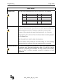
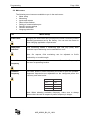
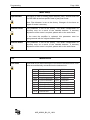
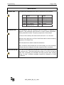
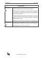
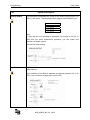
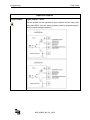
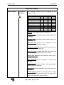
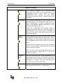
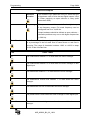
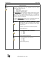
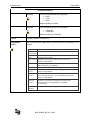
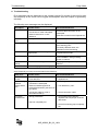
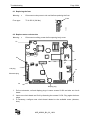
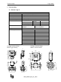
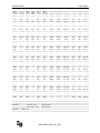
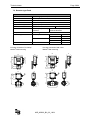
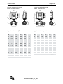
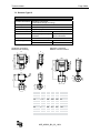
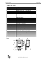
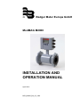
® Badger Meter Europa GmbH ModMAG M2000 INSTALLATION AND OPERATION MANUAL April 2010 MID_M2000_BA_02_1004 Contents Page 1. Basic safety precautions .................................................................................................. 1 2. System description............................................................................................................ 2 3. Installation .......................................................................................................................... 3 3.1 General information ................................................................................................... 3 3.1.1 Temperature ranges ....................................................................................... 3 3.1.2 Protection class .............................................................................................. 3 3.1.3 Transport ........................................................................................................ 4 3.2 Installation .................................................................................................................. 4 3.2.1 Meter orientation ............................................................................................. 4 3.2.2 Inlet and outlet pipe ........................................................................................ 4 3.2.3 Meter location ................................................................................................. 5 3.2.4 Pipe reducer requirements ............................................................................. 6 3.2.5 Separate version ............................................................................................. 7 3.2.6 Grounding and potential equalization ............................................................. 7 3.2.7 Plastic or lined pipelines ................................................................................. 8 3.2.8 Pipelines with cathodic protection ................................................................... 8 3.2.9 Electrically disturbed environment .................................................................. 9 4. Power connections ............................................................................................................ 9 4.1 4.2 Auxiliary power........................................................................................................... 9 Separate version ...................................................................................................... 10 4.2.1 Signal cable specification ............................................................................. 11 4.3 Configuring input/output (I/O)................................................................................... 12 5. Programming ................................................................................................................... 13 5.1 5.2 Quick Setup………………………………………………………………………………..13 Main menu……………………………………………………………… …………………15 5.2.1 Meter Setup……………………………………………….....…………………… 15 5.2.2 Measurement………………………………………………………….…………..16 5.2.3 Inputs and Outputs………………………………………………………………..19 5.2.4 Clear Totals………………………………………………………………………..24 5.2.5 Communications………………………………………………………………… .25 5.2.6 Advanced…………………………………………………………………………..27 5.2.7 Info/Help……………………………………………………………………………30 5.2.8 Language Select………………………………………………………………….31 . … . …. 6. Troubleshooting .............................................................................................................. 32 6.1 6.2 Replacing the fuse ................................................................................................... 33 Replace meter’s electronics ..................................................................................... 33 7. Technical data .................................................................................................................. 34 7.1 7.2 7.3 7.4 7.5 7.6 Detector type II......................................................................................................... 34 Detector type Food .................................................................................................. 36 Detector type III........................................................................................................ 38 Meter type M2000® .................................................................................................. 39 Error limits ................................................................................................................ 40 Size selection ........................................................................................................... 41 8. Program structure ........................................................................................................... 42 9. Return of goods for repair .............................................................................................. 44 Basic safety precautions Page 1/44 1. Basic safety precautions The electromagnetic flow meter is only suitable for the measurement of conductive fluids. The manufacturer is not liable for damages that result from inproper use or from use that is not in accordance with the requirements. The meters are constructed according to state-of-the-art technology and tested operationally reliable. They have left the factory in a faultless condition concerning safety regulations. The mounting, electric installation, putting into operation and maintenance of the meter is to be carried out by suitable technicians. Furthermore the operating personnel has to be trained by the operating authority and the instructions of this manual have to be followed. Basically you have to respect the regulations for the opening and repairing of electrical equipment applicable in your country. Repairs Should you send back a flow meter, please take notice of the following points: - Please enclose a description of the error as well as a precise statement of the measured medium (if necessary a safety specification sheet). - The meter has to be in a cleaned condition (outside and inside). Especially with harmful measuring mediums you have to pay attention that there are no impurities in the pipe or at the connections. - If it is not possible to clean the meter completely, particularly with harmful materials, do not send back the meter. We reserve the right to repair only cleaned meters. Costs, which result from insufficient cleaning, will be charged to you. RoHs Our products are RoHs compliant. MID_M2000_BA_02_1004 System description Page 2/44 2. System description The electromagnetic flow meters are intended for the metering of all fluids with electric conductivity of at least 5 μS/cm (20 μS/cm for demineralized water). These series of meters is characterized by a high degree of accuracy. Measuring results depend on density, temperature and pressure. Measuring principle In accordance with Faraday’s induction principle, electric voltage is induced in a conductor moving through a magnetic field. In case of the electromagnetic flow measurement, the moving conductor is replaced by the flowing fluid. Two opposite measuring electrodes conduct the induced voltage which is proportional to flow velocity to the amplifier. Flow volume is calculated based on pipe diameter. MID_M2000_BA_02_1004 Installation Page 3/44 3. Installation Warning: • Installation instructions given in the following are to be observed in order to guarantee a perfect functioning and a safe operation of the meter. 3.1 General information 3.1.1 Temperature ranges Caution: • In order to prevent a damaging of the meter, you are requested to strictly observe amplifier’s and detector’s maximum temperature ranges. • In regions with extremely high ambient temperatures, foresee a protection from direct sun radiation. • In cases where fluid temperature exceeds 100°C, foresee separate amplifier and detector (separate version). Amplifier Ambient temp. Detector Fluid temp. 3.1.2 -20 to + 60 °C PTFE / PFA -40 to +150 °C Hard rubber 0 to +80 °C Soft rubber 0 to +80 °C Protection class In order to fulfill requirements in respect of the protection class, please follow the following guidelines: Caution: • Body seals need to be undamaged and in proper condition. • All of the body screws need to be firmly screwed. • Outer diameters of the used wiring cables must correspond to cable inlets (for M20 Ø 5....10 mm). In cases where cable inlet is not used, put on a dummy plug. • Tighten cable inlets. • If possible, lead cable away downwards. Thus humidity cannot get into cable inlet. We normally deliver the meter in accordance with protection class IP 67. If you however require a higher protection class, the amplifier is to be installed separately from the detector. If requested, we can also deliver the detector in IP 68. MID_M2000_BA_02_1004 Installation 3.1.3 Page 4/44 Transport Caution: • Use lifting lugs when lifting meter flow tubes that are 150 in diameter or larger. • Do not lift meter on measuring amplifier or on detector’s neck. • Do not lift meter with a fork lift on the jacket sheet. This could damage the body. • Never place rigging chains, forklift forks, etc inside or through the meter’s flow pipe for hoisting the meter. This could damage the isolating liner. 3.2 Installation In order to provide a perfect functioning and to prevent the meter from eventual damages, please follow the following installation instructions. Caution: • • 3.2.1 Carefully observe the forward flow label on the meter body and install the meter accordingly. As for detectors with PTFE liner, remove protective cap on the flange or on the threaded pipes of milk pipe screws as per DIN 11851 not until shortly before installation. Meter orientation Meters can operate accurately in any pipeline orientation. Meters can be installed in horizontal as well as in vertical pipelines. Meters perform best when placed vertically with liquid flowing upward as it prevents solids build-up. When installing the meter on a horizontal pipe, mount the meter to the pipe with the flow-measuring electrode axis in a horizontal plane as it prevents that gas bubbles result in a temporary isolation of the flow-measuring electrodes. Carefully observe the forward flow label on the meter body and install the meter accordingly. 3.2.2 Inlet and outlet pipe Always install the detectors in front of fittings producing turbulences. If this is simply not possible, foresee distances of > 3 x DN. Distance ought to be > 2 x DN. > 2 x DN BA2000-10-MID > 3-5 x DN MID_M2000_BA_02_1004 Installation Page 5/44 3.2.3 Meter location Do not install the detector on the suction sides of pumps. This could damage the liner (in particular PTFE liners). • Verify that the pipeline is always filled on the measuring point, if not - a correct or accurate measurement is not possible. • Do not install the detector on the highest point of a pipeline system. Gas accumulation may follow. • Do not install the detector in downcomer pipes with free outlet. • Do not install the detector on pipes with vibrations. If pipes are strongly vibrating, make sure that detector and amplifier are separated (separate version). >2 N xD N xD BA2000-13-MID -5 >3 BA2000-12-MID BA2000-14-MID BA2000-11-MID h > 2 x DN Caution: • MID_M2000_BA_02_1004 Installation 3.2.4 Page 6/44 Pipe reducer requirements With pipe reducers as per DIN 28545 detectors can be mounted in larger pipelines. You can determine the occurring pressure drop by using the shown nomogram (only applicable to liquids with similar viscosity like water). • In cases where flow velocities are very low, you can increment them by reducing the size on the measuring point and hence obtain a better measuring accuracy. ma x.8 ° Note: BA2000-15-MID D = pipeline d = detector Pressure loss in mbar Diameter ratio d/D Diameter relation d/D Define pressure loss: 1. Calculate diameter ratio d/D. 2. Read pressure loss depending on d/D ratio and flow velocity. MID_M2000_BA_02_1004 Installation 3.2.5 Page 7/44 Separate version Provide a separate version in the following cases: Note: • Detector protection class IP 68 • Fluid temperature > 100 °C • Strong vibrations Do not install the signal cable close to power cables, electric machines, etc. • Fix signal cables. Due to capacity changes, cable movements may result in incorrect measurements. BA2000-16-MID Caution: • 3.2.6 Grounding and potential equalization In order to obtain an accurate measurement, detector and fluid need to be on the same electric potential. If flange or intermediate flange versions with additional grounding electrode are used, grounding is provided by the connected pipeline. Caution: • In case of a type with flange a connection cable (min. 4 mm²) between grounding screw on the meter’s flange to the counterflange is to be used in addition to the fixing screws. Verify that a perfect electric connection is provided. • Color or corrosion on the counterflange may have a negative effect on the electric connection. • In case of types with intermediate flanges, the electric connection to the detector is done via two ¼ AMP plugs installed on detector’s neck. MID_M2000_BA_02_1004 Installation Page 8/44 "X" M4:1 BA2000-17MID "X" 3.2.7 Plastic or lined pipelines If non-conductive pipelines or pipelines lined with non-conductive material are used, install an additional grounding electrode or grounding rings between the flanges. Grounding rings are installed like gaskets between the flanges and are connected with a grounding cable to the meter. When grounding rings are used, please make sure that the material is resistant to corrosion. If aggressive fluids are measured, use grounding electrodes. BA2000-18-MID Caution: • 6 mm² Cu 3.2.8 Pipelines with cathodic protection As for pipelines with cathodic protection, install meter potential-free. No electric connection from the meter to the pipeline system may exist and power supply is to be provided via isolating transformer. Caution: • Observe national rules in respect of a potential-free installation BA2000-19-MID • Use grounding electrodes (grounding rings also need to be installed isolated from the pipeline system). electrically isolated 6 mm² Cu electrically isolated MID_M2000_BA_02_1004 Power connections 3.2.9 Page 9/44 Electrically disturbed environment If the pipe material is in an electrically disturbed environment or if metallic pipelines that are not grounded are used, we recommend a grounding as shown in the following picture in order to assure that measurement is not influenced. BA2000-20-MID PE 6 mm² Cu 4. Power connections • For the 3 x M20 cable inlets only use flexible electric cables. • Use separate cable inlets for auxiliary power, signal and input/output cables. BA2000-21-MID Caution: • Do not connect meter under impressed mains voltage. • Take national applicable rules into account. • Observe type plate (mains voltage and frequency). 1. Slightly loosen both of the left cover screws and loosen the two right cover screws completely. Open cover to the left side. 2. Push auxiliary power cable through the upper cable inlet. 3. Connection as shown in the picture. 4. In the following close connection cover again firmly. N L 85 – 265 VAC MID_M2000_BA_02_1004 BA14MID Warning: F1 2AT 4.1 Auxiliary power Power connections Page 10/44 4.2 Separate version Caution: • Connect or separate signal connection cable only when the unit has been switched off. TP21 2. Loosen upper and lower cover screw and open cover to the left side. 3. Push signal cable on the upper side of the device through cable inlet. 4. Connection as shown in the picture. 5. Close device and connection cover again firmly. Display Loosen both fixing screws of the connection cover and remove cover. Calibrator 1. 13 Shield 12 C2 11 C1 Connection in the measuring amplifier TP2 5MID 45 E1 44 Shield 46 E2 44 Shield 40 EP 44 Shield Connection on the detector Loosen fixing screws of the connection cover and remove cover. 2. Push signal cable through cable inlet. 3. Connection as shown in the picture. 4. Close device and connection cover again firmly. 44 SHIELD SHIELD 44 EMPTY PIPE 40 Shield 44 ELECTRODE 46 Shield 44 ELECTRODE 45 From Detector Shield 13 COIL 12 COIL 11 40 EMPTY PIPE 44 Shield 46 ELECTRODE 44 Shield 45 ELECTRODE To Amplifier 13 SHIELD 12 COIL 11 COIL Badger Meter R JBOX - PRIMO REMOTE - REV1 Terminal box – Terminal Standard Stainless steel 11 5 12 4 13 PE 45 1 44* PE 46 2 40 3 44* PE M2000 Description Wire color C1 C2 CS E1 ES E2 EP ES Coil 1 Coil 2 Main shield Electrode 1 Electrode shield Electrode 2 Empty pipe Empty pipe shield Green Yellow Yellow/Green White Black Brown Pink Black *) Anschlüsse mit der Nr. 44 liegen auf gleichem Potential MID_M2000_BA_02_1004 BA16MID 1. Power connections 4.2.1 Page 11/44 Signal cable specification Note: • Only use signal cables delivered by Badger Meter or corresponding cable in accordance with the following specification. • Take max. signal cable length between detector and amplifier into account (keep distance as low as possible). Distance With electrode idle Loop resistance 0 – 75 m 3 x (2 x 0,25 mm²) =< 160 Ω/km > 75 – 150 m 3 x (2 x 0,50 mm²) =< 80 Ω/km > 150 – 300 m 3 x (2 x 0,75 mm²) =< 40 Ω/km white weiß (45) braun brown (46) schwarz black (44) pink (40) schwarz (44) black pink (40) pink schwarz black (44) 55 bis 300mm to 300 yellow/green (13) gelb/grün (13) yellow/green gelb/grün (13) (13) yellow (12) gelb (12) grün (11) green (11) yellow gelb (12) (12) grün (11) green (11) Cable length [m] Maximum cable length at different fluid temperatures 0,75 mm² 300 275 250 225 200 175 150 125 100 75 50 25 0 0,5 mm² 0,25 mm² 0 25 50 75 100 Temperature [°C] MID_M2000_BA_02_1004 125 150 175 BA17MID white weiß (45) brown braun (46) schwarz (44) black BA17MID PVC cable with pair and total shield Capacity: wire/wire < 120 nF/km, wire/shield < 160 nF/km Temperature range –30 to +70 °C Power connections Page 12/44 4.3 Configuring input/output (I/O) PE Fuse N Auxiliary power Display L Displ 1 2 3 4 5 6 7 CS C2 C1 DISPLAY Jumper JP1 JP2 Jumper JP2 8 9 10 11 12 13 14 E1 ES E2 RS EP ES 15 16 Electrodes detector JP1 COMMUNICATION Memory token BA2000-22MID Coil detector Communication Input/Output Description Analog output 0 - 20 mA 4 - 20 mA 0 - 10 mA Terminal RL < 800 Ohm 16 (+) 15 (-) Digital output 1 Open collector max. 10 kHz * Passive max. 30 VDC, 100 mA * Active 24 VDC, 50 mA (Jumper JP1 placed) 1 (+) and 2 (-) 2 Open collector max. 10 kHz * Passive max. 30 VDC, 100 mA * Active 24 VDC, 50 mA (Jumper JP2 placed) 3 (+) and 4 (-) 3 Open collector passive max. 30 VDC, 100 mA, max. 10 kHz 10 (+) and 11 (-) or Solid State Relais max. 48 VAC, 500 mA, max 1 kHz 4 Open collector passive max. 30 VDC, 100 mA, max. 10 kHz 13 (+) and 14 (-) or Solid State Relais max. 48 VAC, 500 mA, max 1 kHz Digital input 5 - 30 VDC 8 (+) and 9 (-) RS 232 Remote display information or Modbus RTU 7 GND 6 RxD 5 TxD Communication Optional communication ports like HART, Profibus DP, Modbus Communication MID_M2000_BA_02_1004 Programming Page 13/44 5. Programming Programming is accomplished by using the three functional buttons ▲,► and E. You can move from the measuring mode to the programming mode by pressing twice the button E. While first pressing this button, you activate the backlight and while pressing it for a second time, you get into the programming menu. The cursor → on the left side of the display is moved upward and downward with the buttons ▲/ ►. The menu manager or selection from a list is marked with the cursor and acknowledged by pressing the button E. To enter a parameter, the first number is marked with an underline 0. By pressing the buttons + / -, you can increment or decrement them. As soon as the requested number has been selected, you can acknowledge it by pressing the button E. After having entered the last number, the value is stored by pressing the button E or press the button + in order to edit the value again. You get access to the individual menus through three programmable access levels: Administrator, service and user level. Access rights of the individual menu items is shown in the following with three symbols: Administrator Service User For programming the access levels, see the chapter “passwords”. No passwords were set at the factory. 5.1 Quick setup The M2000 amplifier provides you with a quick setup utility that allows you to quickly set most of the important parameters like flow units, totalizer units, full scale flow and low flow cutoff settings. Quick Setup Flow Units Flow units let you select among the flow units mentioned below. Flow units are automatically converted into the selected unit. LPS LPM LPH M3S M3M M3H F3S F3M F3H GPS Unit Liter/Second Liter/Minute Liter/Hour Cubic meters/Sec. Cubic meters/Min. Cubic Cubic Feet/Sec. Cubic Feet/Min. Cubic Feet/Hour. Gallons/Sec. GPM GPH MGD IGS IGM IGH LbM OPM BPM -- MID_M2000_BA_02_1004 Unit Gallons/Min. Gallons/Hour MegaGallon/Da UKG/Sec. UKG/Min. UKG/Hour Pound/Min. Ounce/Min. Barrel/Min. -- Programming Page 14/44 Quick Setup Totalizer Unit This parameter establishes the units of measure for the totalizers: Unit Full Scale Flow Unit L Liters UKG Imperial Gallons HL HectoLiters Lb Pounds M³ Cubic Meters Oz Fluid Ounces CFt Cubic Feet Aft Acre Feet USG U.S. Gallons BBL Barrel MG MegaGallons This parameter sets the maximum flow the system is expected to measure. This parameter has influence on other system parameters. These parameters include: Frequency output and current output. In terms of flow velocity, the meter’s limit are from 0.1 to 12 m/sec. Moreover the values for Low Flow Cut-off and limits monitoring depend on Full Scale Flow. The full scale flow is valid for both flow directions. Note: If the flow rate exceeds the full scale setting, an error message indicates that the configured full scale range has been exceeded. Low Flow Cut-off Low Flow Cut-off defines the threshold at which flow measurement will be forced to zero. The cutoff value can be from 0 % to 9.9 % of the full scale flow. Increasing the threshold will help prevent false reading during “no flow” conditions possible caused by vibrations or liquid fluctuations. MID_M2000_BA_02_1004 Programming Page 15/44 5.2 Main menu The following menu items are available to you in the main menu: • Meter setup • Measuring • Inputs and outputs • Reset of the totalizer • Setting of communication port • Specific counter settings • Counter information • Language selection 5.2.1 Meter Setup Scale Factor Changing the scale factor lets you adjust the meter’s accuracy without disturbing parameters set by the factory. You can tune the meter to meet changing application requirements. Empty Pipe Detection Fluid monitoring shows if measuring pipe has only partly been filled with liquid. Monitoring can be switched on or off. Note: On request, fluid monitoring can be adjusted to fluid’s conductivity or to cable length. Power Line Frequency For an optimum operation of the meter, set Power Line Frequency in this menu at operating location. Excitation Frequency This value shows in which frequency the meter’s coils are operated. Supported frequencies are dependent on the configured power line frequency and meter’s size. 50 Hz 60 Hz 1 Hz 1 Hz 3.125 Hz 3.75 Hz 6.25 Hz 7.5 Hz 12.5 Hz 15 Hz Note: When selecting excitation frequency, make sure to always observe that the ratio in respect of power frequency is integer. MID_M2000_BA_02_1004 Programming Page 16/44 Meter Setup Pipe Diameter This figure is used for setting pipe’s diameter (size). Several sizes DN 6 to DN 2000 as well as specific sizes in [mm] can be set. Note: Pipe diameter is set at the factory. Changes of size have an impact on meter’s accuracy. Detector Factor This parameter is set at the factory. This factor compensates for accuracy error as a result of the installed detector. If accuracy adjustment of the meter is required, please refer to the scale factor. In the event the amplifier is replaced, this parameter must be reprogrammed with the original detector factor. Detector Offset This parameter is set at the factory. This factor compensates for accuracy error as a result of the installed detector. If accuracy adjustment of the meter is required, please refer to the scale factor. Measurement 5.2.2 Flow Units Flow Units let you select among the Flow Units mentioned below. Flow units are automatically converted into the selected unit. LPS LPM LPH M3S M3M M3H F3S F3M F3H GPS Unit Liter/Second Liter/Minute Litre/Hour Cubic meters/Sec. Cubic meters/Min. Cubic Cubic Feet/Sec. Cubic Feet/Min. Cubic Feet/Hour. Gallons/Sec. MID_M2000_BA_02_1004 GPM GPH MGD IGS IGM IGH LbM OPM BPM -- Unit Gallons/Min. Gallons/Hour MegaGallon/Da UKG/Sec. UKG/Min. UKG/Hour Pound/Min. Ounce/Min Barrel/Min -- Programming Page 17/44 Measurement Totalizer Unit This parameter establishes the units of measure for the totalizers: L HL M³ CFt USG MG Full Scale Flow Unit Liters HectoLiter Cubic Meters Cubic Feet U.S. Gallons MegaGallons UKG Lb Oz Aft BBL Unit Imperial Gallons Pounds Fluid Ounces Acre Feet Barrel This parameter sets the maximum flow the system is expected to measure. This parameter has influence on other system parameters. These parametes include: Frequency output and current output. In terms of flow velocity, the meter’s limit are from 0.1 to 12 m/sec. Moreover the values for Low Flow Cutoff and meter’s limits monitoring depend on Full Scale Flow. The full scale flow is valid for both flow directions. Note: If the flow rate exceeds the full scale setting, an error message indicates that the configured full scale range has been exceeded. Low Flow Cut-off Low Flow Cut-off defines the threshold at which flow measurement will be forced to zero. The cutoff value can be from 0 % to 9.9 % of the full scale flow. Increasing the threshold will help prevent false reading during “no flow” conditions possible caused by vibrations or liquid fluctuations. MID_M2000_BA_02_1004 Programming Page 18/44 Measurement Flow Direction Flow direction lets you set the meter to measure forward flow only (unidirectional) or both forward and reverse flow (bidirectional). Unidirectional means that the flow is totalized in only one direction. The flow direction is indicated by the arrow printed on the detector label. In this mode, the two totalizers T1/T2 can be used as totalizers and resettable day counters. Bidirectional means the flow is totalized in both directions. The totalizer T+ registers forward flow and the totalizer T-totalizes in reverse flow direction. The net totalizer TN registers total flow and shows the difference between T+ and T-. A change of the flow direction can be signalized by the digital outputs. Damping Factor The damping factor establishes the stability of the measured flow rate.Time constant can be set from “none” up to a max. of 30 seconds. Note: Damping has no influence on the totalizers. MID_M2000_BA_02_1004 Programming Page 19/44 Inputs and Outputs 5.2.3 Analog Output This parameter establishes the range of the analog output signal: 0 to 100% (= full scale). The following current ranges are available to you: Current output 0 to 20 mA 4 to 20 mA 0 to 10 mA 2 to 10 mA Note: In case that an error message is displayed, set current to 22 mA. In case that you select bidirectional operation, you can signal flow direction via digital outputs. Also see full scale setting. Digital Input Digital input lets you reset totalizers, preselections or interrupt flow measurement. Input switching is provided by applying an external potential of 5 to 30 VDC or by an internal voltage source of 24 VDC. MID_M2000_BA_02_1004 Programming Page 20/44 Inputs and Outputs Digital Outputs In the sub-menu “Functional operation“ you can configure functional operation of the 4 digital outputs. You can select e.g “forward pulse” for the digital output and define the pulses per totalizer unit via “pulse scale”. Digital outputs 1 and 2 The two outputs can be operated as open collector passively or actively. Setting can be done via the hardware Jumper JP1 or JP2. Jumper placed means “active output operation“, otherwise “passive output operation“. Jumper placement on circuit board, see chapter 4.3 Configuring inputs and outputs. MID_M2000_BA_02_1004 Programming Page 21/44 Inputs and Outputs Digital Outputs Digital outputs 3 and 4 The two outputs can be operated as open collector and as relay (solid state relais SSR). You can select operating mode by programming the relative outputs (output hardware). MID_M2000_BA_02_1004 Programming Page 22/44 Inputs and Outputs Digital Outputs Functional selection The following functions can be selected for the outputs 1 to 4: Function Inactive Forward pulse Reverse pulse AMR (50 ms) Frequency Flow set point Empty pipe alarm Flow direction Preset output Error alarm 24 VDC Supply Dig1 X X X X X X X X X X Dig2 X X X X X X X X X Dig3 X Dig4 X X X X X X X X X X X X Inactive means digital output is switched off. Forward pulse generates pulses during forward flow conditions. Reverse pulse generates pulses during reverse flow conditions. AMR (50 ms) serves for an adaptation to the “Automatic Meter Reading“ system. Frequency output generates pulses correlated to the absolute value of the flow rate. Flow set point provides indication when flow rate exceeds thresholds defined by flow set points. Empty pipe alarm provides indication when pipe is empty. Flow direction provides indication on current flow direction Preset output provides indication when preset batch amount has been realized. Error alarm provides indication when meter has error condition. 24 VDC Suppy provides constant 24 volts on output (forces output type to normally open. The jumper JP1 or JP2 must be placed (active output). MID_M2000_BA_02_1004 Programming Page 23/44 Inputs and Outputs Pulses/Unit The Pulses/Unit parameter lets you set how many pulses per unit of measure will be transmitted. The configurable range is from 0.0001 to 99.999 pulses/volume unit, however the max. output frequency of 10,000 pulses/sec. (10 kHZ) must not be exceeded. Pulse Width This parameter establishes the “On” duration of the transmitted pulse. The configurable range ist from 0 msec to 9999 msec. If 0 msec is configured, pulse width is automatically adapted depending on pulse frequency (pulse/pause ratio 1:1). During the configuration the program checks if pulses/unit and pulse width are in accordance with full scale defined, if not an error alarm is displayed. In case of an error alarm, scale, pulse width or full scale need to be adapted. Preset amount lets you set the reset value for the associated PS totalizer when the digital input is set to Batch Reset. You can configure preset amounts from 0.01 to 99999.99 totalizer units in steps of 0.01 volume units. Preset Amount Preset amount is counted down from the configured value to 0 and a digital output shows that the preset amount has been reached. Note: You can only set one preset amount. If you set the preset amount for digital output 1, it will be the same for 2, 3 and 4. Flow Set Point The Flow Set Point (min, max) establishes as a percentage of full scale flow, the threshold at which the output alarm will be activated. You can freely select thresholds in 1% steps. Flow rates below/above the threshold will activate the output alarm. Output Type The Output Type parameter lets you set the output switch to “normally closed“ or “normally open“. MID_M2000_BA_02_1004 Programming Page 24/44 Inputs and Outputs Hardware selection The hardware type parameter lets you select the type of hardware used to drive the two digital outputs 3 and 4: Either passively as open collector or relay (solid state relais SSR). Frequency This parameter establishes to define the digital output 3 as frequency output. Full scale frequency can be configured from 0 to 10,000 Hz. Output hardware should be defined as open collector – otherwise problems may occur with higher frequencies (> 500 Hz). Flow Simulation 5.2.4 Flow Simulation provides analog and digital output simulation based on a percentage of the full scale flow in cases where no real flow is occurring. The range of simulation includes -100% to +100% in steps of 10% of the full scale flow. Clear Totals T1 The unidirectional totalizer T1 is reset within the menu manager. T2 The unidirectional totalizer T2 is reset within the menu manager or with digital input. T+ The bidirectional totalizer T+ is reset within the menu manager. T- The bidirectional reverse flow totalizer T- is reset within the menu manager. TN The bidirectional net TN is reset within the menu manager. VW The preset batch is reset within the menu manager or with digital input. Tpwroff The totalizer accumulating meter time is reset within the menu manager. MID_M2000_BA_02_1004 Programming Page 25/44 Communications 5.2.5 Port A The port configuration lets you communication port will be used: • • • configure how the RS232 Modbus RTU Remote Menu (remote control) Disable Port (deactivate port ) The Remote Menu port will check for display updates once a second. If a change is detected, the display contents will be transmitted in ASCII format over the RS232 communication port. If a suitable PC program is used, the display cannot only be displayed on the PC but the counter can also be configured. The function Modbus RTU allows access via a Modbus address that you can configure from 1 to 247 in the menu “Port A Adress“. Port Adress The range of addresses supported is 1-247. Requests will only be processed if the configured port address of the meter matches with the request address found. Address 0 is processed as “broadcast packets“. Default adress is [1]. Baud Rate The following baud rates are supported: • • • 9600 19200 38400 Default setting is [9600 baud]. Parity The following parities are supported: • • • Even Odd None Default setting is [Even] MID_M2000_BA_02_1004 Programming Page 26/44 Communications 5.2.5 Data Bits The following data bits are supported: • • • 8 bits 7 bits 5 bits Default settting is [8 bits] Stop Bits The following stop bits are supported: • • 1 Stop Bit 2 Stop Bits Default setting is [1 Stop Bit] Port B This port cannot be configured. Diagnostics Port A This function allows diagnostics in cases where the port Modbus RTU is used. Counter Description Pkts Processed Broadcast Pkts CRC Errors Number of packets processed by meter. Pkts Rcvd Pkts Sent Parity Errors Framing Errors Number of broadcast packets (Address = 0) processed by meter. Number of received packets with CRC error; packet is discarded. Number of packets received with an address of the configured port address No. of packets transmitted in response to a received Number of characters with parity errors; packet is discarded. Number of characters with framing error (e.g. missing stop bit – synchronization problem); packet is discarded. Overrun Errors Number of received characters that were not processed due to degradation of system performance. Break Detects Number of breaks during transmission. MID_M2000_BA_02_1004 Programming Page 27/44 Advanced 5.2.6 Unit Multiplier This function lets you define totalizers’ formatting. You can select among the following formats: Format 0.0001 1 0.001 10 0.01 100 0.1 1000 Formatting is normally [Aus/off]. With this function, the best possible resolution is automatically chosen. Backlight Control You can set the meter’s backlight to “Aways On“, “Always Off“ or “Time (1 min)”. When set to “Time (1 min)“, the backlight will automatically turn off after one minute of inactivity (no buttons pressed). Pressing one of three buttons will turn the backlight on. Note: A longer operation with the option „always on“ can have a negative effect on LCD’s life. Analog Calibrate Analog calibrate lets you configure the current output. Note: The analog output was already set at the factory. Normally an additional calibration is not necessary. In the event that you wish to adapt the output to your external system, see “corrective factor“. Corrective Factor The analog output was already set at the factory to exactly 4.00 mA (zero) und 20.00 mA (margin). In the event that your external system shows another parameter, you can simply correct the offset via this function. First select “Set 4 mA Offset“ and enter another parameter for zero. In the event that your system shows 3.70 mA instead of 4.00 mA, enter the difference of -00.30 mA as corrective factor. The same applies to the item “Set 20 mA Offset“ in order to correct the margin. MID_M2000_BA_02_1004 Programming Page 28/44 Advanced Factory setting Software Filter The analog output was already set at the factory to exactly 4.00 mA (zero) and 20.00 mA (margin). In case that you wish to adapt your external system, use the item “corrective factor“. This filter is intended to help eliminate unrequested peaks during measurement. Activation Activates or deactivates the software filter Filter Delay Filter Delay lets you set the amount of time that the flow will be held constant once the filter is activated (change of flow per time unit). Acceleration Factor This parameter lets you set the maximum acceleration for a given pipe diameter (change of flow per time unit). If the realized fluid acceleration exceeds the configured maxi-mum acceleration, fluid flow will be held constant for the time set at the Filter Delay parameter. Constant Flow This parameter lets you set the acceleration limit for a constant flow. Peak Detect Peak Defect offers a diagnostic view of acceleration components observed during flow condition and records the “high water mark“. Press + button to reset. MID_M2000_BA_02_1004 Programming Page 29/44 Advanced Empty Pipe Cal. Note: To compensate different fluid conductivity, signal cable lengths or sizes during measurements, you can calibrate them accordingly. This is important in case that fluid monitoring has been activated and “empty pipe” is signalized although the pipe is filled. Proceed as follows: 1. Select “Empty Pipe Cal“ 2. Set calibration to “CAl [on]“ 3. Observe the voltage “Volt“ 4. When stable, select “Store“ and press E 5. Fill pipe with fluid 6. Select “Cal. Pipe Full“ 7. Set calibration to “Cal [AN]“ 8. Observe the voltage “Volt“ 9. When stable, select “Store“ and press E 10. Password Security There are three possible access levels, each with its own unique password: • Administrartor PIN • Service PIN • User PIN The password security consists of a five-digit PIN and is set at the factory to [00000]. Enter a number above zero to activate password security. Activate password security in the following order: Administrator, Service, User. Note: You cannot activate the user password before administrator and service passwords have been activated. About 5 minutes after configuration, password security becomes active. As soon as password security has become active, a PIN is required for configuration. Depending on the individual PINs, you are either in the administrator, service or user levels with corresponding access rights (identified in the operating manual by the lock A, S and B). MID_M2000_BA_02_1004 Programming Page 30/44 Info/Help 5.2.7 Error Counts The following list gives you an overview about the kind and frequency of various messages and hence provides a diagnostic of the counter or the measuring point. Prior to any diagnostic, we suggest to reset the individual parameters in order to exclude impacts occurring due to installation, maintenance or other anormal operation conditions. You can reset the individual parameters by selecting them with the cursor and by pressing E. Select “number“ and press E [J]. Select „store“ and press again E. Rollover Counts Detector The number of times an invalid detector condition has been observed Empty Pipe The number of times an empty pipe condition has been observed by the meter Full Scale The number of times the flow has exceeded the full scale setting Totalizer The number of times the totalizers have exceeded limits of the meter Pulse Sync. The number of times the pulse outputs have fallen out of synchronization ADC Interrupt The number of times an analog input measurement has been missed ADC Range The number of times the analog input measurement range has been exceeded System Error A diagnostic system message indicating the reason for a system reset System Resets The number of times the meter has been reset System Reset ID Diagnostic information about a system reset as a result of expired internal timers The number of times the totalizers have rolled over. Note: The totalizer can show a max. of 10 digits in the display. In the following, it is set to zero again and rollover count is incremented by one. MID_M2000_BA_02_1004 Programming 5.2.7 Page 31/44 Info/Help PowerUp Counter The number of times that the unit has been powered on. Power Off Time The length of time that the unit has been without power. This parameter “Tpwroff“ can be set with the menu “Reset Totalizer“. Version info The current software version of the unit. Serial number The manufacturing serial number of the installed electronics in the format YYMM####. Restore Default Restores all non-calibrated parameters to the factory defaults. Restore Calibration Restores the meter calibration as set at the factory. 5.2.8 Language select Language Select The unit supports English along with one alternate language. The alternate language choice is set at the factory. MID_M2000_BA_02_1004 Troubleshooting Page 32/44 6. Troubleshooting Error messages can be displayed via the 4 digital outputs. By means of the error list type and frequency of the errors can be logged and analyzed, also see chapter Programming: Info/Help. The following error messages can be displayed: Description Possible Cause Recommended Action Err: Coil Meter not connected. Check if meter is connected and make sure that cable connection is not interrupted. Connection to meter interrupted. Detector electronics or coils defective. Wrn: Pulse Sync False synchronization of pulse output Err: empty pipe Pipe may not be full. Otherwise contact Service Department. Make sure that pipe is always filled at the measuring point. Eventually calibrate anew, see calibration of fluid monitoring Err: full scale Actual flow rate is exceeding the programmed. Reduce flow rate or increase the programmed full scale. Err: ADC range Input signal from detector too high. Check the grounding scheme of the meter installation. See grounding section in manual. Err: Tot. rollover Number of totalizer digits is exceeded See programming / Info/Help / Totalizer Rollover Err: ATOD INT No measuring signal on analog input. Contact service. Some frequently occurring errors are listed in the following: Other error Possible Cause Recommended Action Meter does not function No auxiliary power. Provide auxiliary power. Fuse defective. Replace fuse. Fluid is flowing, Signal cable is not connected or Check signal cable. however connection is interrupted. display shows Detector installed opposite to Turn detector by 180°. zero forward flow direction (see arrow on type plate). Inaccurate measurement Connection cable for coils or electrodes mixed-up. Check connection cable. Wrong parameters. Check parameters (detector, amplifier and size) as per annexed data sheet Pipe not completely full. Check if measuring pipe completely full. MID_M2000_BA_02_1004 Troubleshooting Page 33/44 6.1 Replacing the fuse Warning: • Disconnect main power to the unit before replacing the fuse. Fuse T2 H 250 V (2A idle) F1 2AT Fuse type: BA14MID N L 6.2 Replace meter’s electronics Warning: • Disconnect auxiliary power before opening body cover. L N PE S1 S2 S5 JP1 1 2 3 4 5 6 7 CS C2 C1 DISPLAY S6 JP2 Coil plug 15 16 Electrode plug 8 9 10 11 12 13 14 E1 ES E2 RS EP ES COMMUNICATION S3 BA2000-22MID S4 Display plug 1. Pull out electrode, coil and display plugs. Loosen screws S1-S6 and take out circuit board. 2. Insert new circuit board and fix it by fastening the screws S1-S6. Plug again the three plugs. 3. If necessary, configure new circuit board related to the available meter (detector, size). MID_M2000_BA_02_1004 Technical data Page 34/44 7. Technical data 7.1 Detector Type II Technical data Size Process connections Nominal pressure Protection class Min. conductivity Liners DN 6 – 2000 (1/4“...80“) Flange: DIN, ANSI, JIS, AWWA etc. Up to PN 100 IP 67, IP 68 optional 5 µS/cm (20 µS/cm demineralized water) Hard/soft rubber 0 to +80°C from DN 25 onward PTFE DN 6 - 600 -40 to +150°C Halar (ECTFE) ab DN 300 -40 to +150°C Hastelloy C (Standard) Platinum/Gold platinized Tantalum Platinum/Rhodium Steel/stainless steel optional DN 6 – 20 170 mm DN 25 – 50 225 mm DN 65 – 100 280 mm DN 125 – 200 400 mm DN 250 – 350 500 mm DN 400 – 750 600 mm DN 800 – 1000 800 mm DN 1200 – 1400 1000 mm DN 1600 1600 mm DN 1800 1800 mm DN 2000 2000 mm Electrodes Body Overall length Process connection flange M2000® wall mounting Process connection flange M2000® mounted version 180 99 83 60 .2 Ø5 B2 65 M20 (x3) 180 281 M20 (x3) 180 180 80 K MID_M2000_BA_02_1004 D K M2000-2 A M2000-3 A D DN d2 x n B1 DN 120 d2 x n 122 Technical data Page 35/44 ANSI flanges DN A Std* DIN flanges 6 1/4” 170 A ISO** --- B1 B2 ∅D ∅K ∅ d2xn ∅D ∅K ∅ d2xn 228 288 88,9 60,3 15,9 x 4 90 60 14 x 4 8 3/10” 170 --- 228 288 88,9 60,3 15,9 x 4 90 60 14 x 4 10 3/8” 170 --- 228 288 88,9 60,3 15,9 x 4 90 60 14 x 4 15 1/2” 170 200 238 298 88,9 60,3 15,9 x 4 95 65 14 x 4 20 3/4” 170 200 238 298 98,4 69,8 15,9 x 4 105 75 14 x 4 25 1” 225 200 238 298 107,9 79,4 15,9 x 4 115 85 14 x 4 32 1 1/4” 225 200 253 313 117,5 88,9 15,9 x 4 140 100 18 x 4 40 1 1/2” 225 200 253 313 127 98,4 15,9 x 4 150 110 18 x 4 50 2” 225 200 253 313 152,4 120,6 19 x 4 165 125 18 x 4 65 2 1/2” 280 200 271 331 177,8 139,7 19 x 4 185 145 18 x 4 80 3” 280 200 271 331 190,5 152,4 19 x 4 200 160 18 x 8 100 4” 280 250 278 338 228,6 190,5 19 x 8 220 180 18 x 8 125 5” 400 250 298 358 254 215,9 22,2 x 8 250 210 18 x 8 150 6” 400 300 310 370 279,4 241,3 22,2 x 8 285 240 22 x 8 200 8” 400 350 338 398 342,9 298,4 22,2 x 8 340 295 22 x 12 250 10” 500 450 362 422 406,4 361,9 25,4 x 12 395 350 22 x 12 300 12” 500 500 425 485 482,6 431,8 25,4 x 12 445 400 22 x 12 350 14” 500 550 450 510 533,4 476,2 28,6 x 12 505 460 22 x 16 400 16” 600 600 475 535 596,9 539,7 28,6 x 16 565 515 26 x 16 450 18” 600 --- 500 560 635,0 577,8 31,7 x 16 615 565 26 x 20 500 20” 600 --- 525 585 698,5 635,0 31,7 x 20 670 620 26 x 20 550 22” 600 --- 550 610 749,3 692,1 34,9 x 20 --- --- --- 600 24” 600 --- 588 648 812,8 749,3 34,9 x 20 780 725 30 x 20 650 26” 600 --- 613 673 869,9 806,4 34,9 x 24 --- --- --- 700 28” 600 --- 625 685 927,1 863,6 35,1 x 28 895 840 30 x 24 750 30” 800 --- 650 710 984,2 914,4 34,9 x 28 --- --- --- 800 32” 800 --- 683 743 1060,5 977,9 41,3 x 28 1015 950 33 x 24 850 34” 800 --- 708 768 1111,2 1028,7 41,3 x 32 --- --- --- 900 36” 800 --- 725 785 1168,4 1085,8 41,3 x 32 1115 1050 33 x 28 950 38” 800 --- 750 810 1238,3 1149,4 41,3 x 32 --- --- --- 1000 40” 800 --- 790 850 1346,2 1257,3 41,3 x 36 1230 1160 36 x 28 1200 48” 1000 --- 900 960 1511,5 1422,4 41,3 x 44 1455 1380 39 x 32 1350 54” 1000 --- 975 1035 1682,8 1593,9 47,8 x 44 --- --- --- 1400 56” 1000 --- 1000 1060 --- --- --- 1675 1590 42 x 36 Standard ANSI flanges from DN 6 - 2000 pressure 150 lbs DIN flanges from DN 6 – 200 pressure PN 16 from DN 250 – 2000 pressure PN 10 * Standard **ISO 13359 MID_M2000_BA_02_1004 Technical data Page 36/44 7.2 Detector type Food Body Overall length DN 10 – 100 (3/8“...4“) Tri-Clamp®, DIN 11851, ISO 2852, etc. PN 10 IP 65, IP 68 optional 5 µS/cm (20 µS/cm demineralized water) PTFE -40 to +150°C Hastelloy C (Standard) Platinum/Gold platinized Tantalum Platinum/Rhodium Stainless steel Tri-Clamp® connection DN 10 – 50 145 mm DN 65 – 100 200 mm DIN 11851 connection DN 10 – 20 170 mm DN 25 – 50 225 mm DN 65 – 100 280 mm Process connection Tri-Clamp® M2000® Wall mounting 180 281 M20 (x3) .2 Ø5 60 281 .2 Ø5 60 99 180 99 180 180 Process connection DIN 11851 M2000® Wall mounting M20 (x3) Technical data Size Process connections Nominal pressure Protective class Min. conductivity Liners Electrodes 65 65 122 80 80 A MID_M2000_BA_02_1004 D M2000-7 DN M2000-6 A D DN B1 B1 120 120 122 Technical data Page 37/44 Process connection Tri-Clamp® M2000® mounted version 180 M20 (x3) 180 DN B2 M2000-9 D A A Type Food Tri-Clamp ® DN 83 M2000-8 DN B2 M20 (x3) 180 83 D 180 Process connection DIN 11851 M2000® mounted version Type Food Milk Pipe DIN 11851 A B1 B2 D DN 10 A B1 B2 D 3/8” 170 238 184 74 15 1/2” 170 238 184 74 10 3/8” 145 228 174 74 15 1/2” 145 228 174 74 20 3/4” 170 238 184 74 20 3/4” 145 228 174 74 25 1” 225 238 184 74 25 1” 145 228 174 74 32 1 ¼“ 225 243 189 84 40 1 ½“ 145 238 184 94 40 1 ½“ 225 248 194 94 50 2” 225 253 199 104 50 2” 145 243 189 104 65 2 ½“ 280 266 212 129 65 2 ½“ 200 256 202 129 80 3” 280 271 217 140 80 3” 200 261 207 140 100 4” 280 279 225 156 100 4” 200 269 215 156 Pressure PN 10 Pressure PN 16 Dimensions (mm) MID_M2000_BA_02_1004 Dimensions (mm) Technical data Page 38/44 7.3 Detector Type III Technical Data Size Process connections Nominal pressure Protective class Min. conductivity Liner Electrodes Body Overall length DN 25 – 100 (1“...4“) Sandwich connection, (intermediate flange mounting) PN 40 IP 67, IP 68 optional 5 µS/cm (20 µS/cm demineralized water) PTFE -40 to +150°C Hastelloy C (Standard) Platinum/Gold platinized Tantalum Platinum/Rhodium Steel/stainless steel optional DN 25 – 50 100 mm DN 65 – 100 150 mm Sandwich connection M2000® wall mounting Sandwich connection M2000® mounted version 99 180 B2 65 M20 (x3) .2 Ø5 DN 120 B1 M2000-5 D DN A A DN A B1 B2 D 25 1” 100 238 184 74 32 1 ¼“ 100 243 189 84 40 1 ½“ 100 248 194 94 50 2” 100 253 199 104 65 2 ½“” 150 266 212 129 80 3” 150 271 217 140 100 4” 150 279 225 156 Pressure PN 40 MID_M2000_BA_02_1004 M2000-4 80 122 D 60 83 180 281 M20 (x3) 180 180 Technical data Page 39/44 7.4 Meter type M2000® Technical data Type Auxiliary power M2000® 85 – 265 VAC, 45 – 65 Hz Optional 24 VDC (-10% … +20%), 900 mA 0/4 – 20 mA, ≤ 800 Ohm Flow direction is displayed via separate status output 4 freely configurable open collector outputs Active 24 V, 50 mA or Passiv 30 VDC, 100 mA max. frequency of 10 kHz Pulse, limit, preselector, statur, error messages Totalizers and preselectors reset Positive Zero Return Separate electrode 3 buttons RS 232 – Remote display or Modbus RTU 0,03 to 12 m/s ≥ 0,5 m/sec. better ±0,25% < 0,5 m/sec. ±1,25 mm/sec. 0,1% Bidirectional Configurable up to 2000 msec. Short-circuit-proof and galvanically separated 0 – 10% LCD, 4 lines/20 digits, backlight, actual flow rate, totalizers, status display Powder-coated alu die casting IP 67 Supply and signal cables 3 x M20 From meter M20 -20 to + 60°C Digital outputs Digital inputs Fluid monitoring Configuration Ports Measuring range Measuring accuracy Reproducibility Flow direction Pulse length Outputs Low flow cutoff Display Body Protective class Cable inlet Signal cable Ambient temperature Dimensions M2000® 99 281 M20 (x3) 180 180 60 .2 Ø5 65 MID_M2000_BA_02_1004 M2000-1 Analog output Technical data Page 40/44 7.5 Error limits Measuring range : 0,03 m/sec. to 12 m/sec. Pulse output : ≥ 0,5 m/sec. ±0,25% < 0,5 m/sec. ± 1,25 mm/sec. Analog output : Similar to pulse output plus ±0,01 mA Reproducibility : ±0,1% Measurement in % Meßfehler inerrors % v.M. Fehlerkurve MID M2000 Error curve MAG meter M2000 5% 4% 3% 2% 1% 0% 0 1 2 3 4 5 6 7 Fluid velocity v[m/sec.] v[m/s] Mediumsgeschwindigkeit Reference conditions: Ambient and fluid temperature : 20°C Electr. conductivity : > 300 μS/cm Warm-up period : 60 min Mounting conditions : > 10 DN inlet pipe > 5 DN outlet pipe Detector properly grounded and centered. MID_M2000_BA_02_1004 8 9 10 Technical data Page 41/44 7.6 Size select DN 6 - DN 100 100 m/s 10 1 0,1 0,01 0,01 0,1 1 10 100 1.000 10.000 L/min DN 125 - DN 1400 100 10 1 0,1 0,01 1 10 100 1000 m³/h MID_M2000_BA_02_1004 10.000 100.0 Program structure Page 42/44 8. Program structure Start Menu Quick Setup Flow Unit Totalizer Unit Main Menu Meter Setup Scale Factor Empty Pipe Detect Power Line Freq Excitation Freq Pipe Diameter Detector Factor Detector Offset Measurem Measurements Inputs/Outputs Flow Unit Totalizer Unit Full Scale Flow Low Flow CutOff Flow Direction Damping Factor Analog Output Digital Input Digital Output #1 Full Scale Flow On Off Unidirectional Bidirectional None Remote Reset Batch Reset Pos Zero Return Pulses / Units Pulse Width Preset Amount Set Point Min. Set Point Max. Output Type Select Function Digital Output #2 Pulses / Units Pulse Width Preset Amount Set Point Min. Set Point Max. Output Type Select Function Clear Totals Communications Advanced Info/Help Language Select Low Flow Cut-off Digital Output #3 Digital Output #4 Flow Simulation MID_M2000_BA_02_1004 Normally Open Normally Closed None Forward Pulse Reverse Pulse AMR(50ms Pulse) Flow Set Point Empty Pipe Alarm Flow Direction Preset Output Error Alarm 24 VDC Supply Normally Open Normally Closed None Forward Pulse Reverse Pulse Flow Set Point Empty Pipe Alarm Flow Direction Preset Output Error Alarm 24 VDC Supply Program structure Start Menu Main Menu Page 43/44 Inputs/Outputs Digital Output #3 Digital Output #4 Full Scale Freq Preset Amount Set Point Min. Set Point Max. Output Type Normally Open Normally Closed Hardware Select Relay Open Collector Select Function None Frequency Output Flow Set Point Empty Pipe Alarm Flow Direction Preset Output Error Alarm Full Scale Freq Set Point Min. Set Point Max. Output Type Normally Open Normal Closed Hardware Select Relay Open Collector Select Function None Flow Set Point Empty Pipe Alarm Flow Direction Preset Output Error Alarm Interface Port Address Baud Rate Data Bits Parity Stop Bits Modbus RTU (DEF) Remote Menu Disable Port Flow Simulation Clear Totals Communications Port A Settings Port B Settings Diagnostics Advanced Unit Multiplier Backlight Control Analog Calibrate Software Filter Empty Pipe Cal. Security Error Counts Rellover Counts PowerUp Counter PowerOff Totalizer Version Info Serial Number Restore Default Restore Calibration Info/Help Set Admin. Pin Set Service Pin Set User Pin Language Select MID_M2000_BA_02_1004 Return of goods for repair Page 44/44 9. Return of goods for repair Please copy, fill in and sign hereafter harmlessness declaration and enclose it for any return of goods you may send back for repair. No repair will be performed prior to receiving the harmlessness declaration duly filled and signed. Harmlessness declaration To : __________________________________________________________________ Attn. : __________________________________________________________________ From : __________________________________________________________________ Dept. : __________________________________________________________________ Please note that no repair will be performed prior to receiving of this declaration duly signed by you! Please send all parts clean from medium and inform us about possible medium wastes remaining in the part. For this purpose, please use this form. A security specification sheet of the medium must accompany this declaration in the following cases: Toxical, dangerous or objectionable media, or media belonging to any dangerous materials class. We inform you that uncleaned parts lead to additional costs. Extra clean costs will be charged to you. Furthermore, we reserve us the right to send the parts back to you for cleaning! Declaration We herewith confirm that the part(s) sent for repair has/have been cleaned and is/are free of any liquid and/or solid wastes of the medium and/or cleaning medium: Any eventually remaining wastes are: harmless dangerous, toxic, etc. – Security specifications are attached Signature of person in charge: ______________________________________ Name of the person in charge in capital letters: ______________________________________ Date: ______________________________________ Company stamp: ______________________________________ MID_M2000_BA_02_1004 (passiv) tsRelais 1 Skalenendwert Hotline Phone +49-7025-9208-0 or -30 Fax +49-7025-9208-15 ® Badger Meter Europa GmbH Subsidiary of Badger Meter, Inc., USA Nürtinger Strasse 76 72639 Neuffen (Germany) E-mail: [email protected] www.badgermeter.de