1
VERSION
1.2 - 1.3
ltra
708 U Jul-03
0
Ver 1.0
708ULT
REFERENCE & INSTALLATION MANUAL
TABLE OF CONTENTS
INTRODUCTION ............................................................................................................. 4
About This Manual .............................................................................................................................
New Features.....................................................................................................................................
Specifications.....................................................................................................................................
About Paradox ...................................................................................................................................
4
4
4
4
Installation...................................................................................................................... 5
Location and Mounting....................................................................................................................... 5
Earth Ground ..................................................................................................................................... 5
Auxiliary Power Terminals .......................................................................................................................................... 5
Keypad Function Test................................................................................................................................................. 5
Telephone Line Connection ...............................................................................................................
Keypad Connections..........................................................................................................................
Keypad Zone Connections.................................................................................................................
Connecting a Tamper Switch on an LED Keypad..............................................................................
Single Zone Input Terminal Connections...........................................................................................
5
7
7
9
9
N.C. Contacts, Without EOL Resistor ......................................................................................................................... 9
N.O. and N.C. Contacts, With EOL Resistor (UL/ULC) .............................................................................................. 9
N.C. Contacts, Without EOL Resistor, With Tamper Recognition ............................................................................ 10
N.C. Contacts, With EOL Resistor, With Tamper and Wire Fault Recognition (UL/ULC)......................................... 10
Advanced Technology Zone (ATZ) Connections ............................................................................. 11
N.C. Contacts, Without EOL Resistor .......................................................................................................................
N.C. Contacts, Without EOL Resistor, With Tamper Recognition ............................................................................
N.C. Contacts, With EOL Resistor, With Tamper & Wire Fault Recognition (UL/ULC) ............................................
ATZ Parallel Wiring ...................................................................................................................................................
11
11
12
12
Installer Code................................................................................................................................... 13
Installer Lock.................................................................................................................................... 13
PROGRAMMING METHODS ....................................................................................... 14
Espload Software............................................................................................................................. 14
Keypad............................................................................................................................................. 14
Hexa Programming ...................................................................................................................................................
Hexa Streamlined Section Programming..................................................................................................................
Decimal Programming ..............................................................................................................................................
Feature Select Programming ....................................................................................................................................
14
15
16
16
PANEL SETTINGS FOR ESPLOAD ............................................................................ 17
Panel Answer Options .....................................................................................................................
Panel Identifier .................................................................................................................................
PC Password ...................................................................................................................................
Computer Telephone Number .........................................................................................................
Call Espload.....................................................................................................................................
Answer Espload ...............................................................................................................................
Cancel Communication....................................................................................................................
Call Back..........................................................................................................................................
17
17
17
18
18
18
18
18
EVENT REPORTING .................................................................................................... 19
ESPRIT 708 ULTRA
1
Reporting Options ........................................................................................................................... 19
Reporting Disabled ...................................................................................................................................................
Regular Reporting ....................................................................................................................................................
Split Reporting ..........................................................................................................................................................
Double Reporting......................................................................................................................................................
Central Station Telephone Number 1..............................................................................................
Central Station Telephone Number 2..............................................................................................
System Account Codes ...................................................................................................................
Communicator Formats...................................................................................................................
Ademco Contact ID (all codes).................................................................................................................................
Ademco Contact ID (programmable codes) .............................................................................................................
Ademco Express ......................................................................................................................................................
Pager Reporting Format ...........................................................................................................................................
Standard Pulse Formats...........................................................................................................................................
Pager Delay.....................................................................................................................................
Pager Format Transmission Options...............................................................................................
Pager Report Event Option .............................................................................................................
Reporting Event Codes ...................................................................................................................
Alarm Codes.............................................................................................................................................................
Restore Codes..........................................................................................................................................................
Tamper Codes..........................................................................................................................................................
Trouble / Trouble Restore Codes .............................................................................................................................
Special Codes ..........................................................................................................................................................
20
20
20
20
21
21
22
22
22
23
23
23
24
24
24
24
24
25
25
25
25
25
Auto Test Report ............................................................................................................................. 26
Manual Test Report......................................................................................................................... 26
ZONE DEFINITIONS .................................................................................................... 27
Zone Speed..................................................................................................................................... 27
Advanced Technology Zoning (ATZ)............................................................................................... 27
ATZ Parallel Wiring................................................................................................................................................... 28
Intellizones ...................................................................................................................................... 28
Intellizone Time Delay .............................................................................................................................................. 28
EOL Zones (Enabled/Disabled)....................................................................................................... 28
Keypad Zone 1 Supervision ............................................................................................................ 28
Keypad Zone 2 Supervision ............................................................................................................ 28
OTHER OPTIONS ........................................................................................................ 29
Telephone Line Monitoring (TLM) ...................................................................................................
Dialing Options ................................................................................................................................
Dialing Pulse Rates .........................................................................................................................
Panel Time ......................................................................................................................................
Time Correction...............................................................................................................................
Tamper / Wire Fault Recognition Options .......................................................................................
Audible Trouble Warning.................................................................................................................
Power Down Reset..........................................................................................................................
29
29
29
29
29
30
30
30
USER / KEYPAD FUNCTIONS .................................................................................... 31
Alarm Memory ................................................................................................................................. 31
Keypad Chime Zones...................................................................................................................... 31
Trouble Display Monitoring.............................................................................................................. 31
Communicator Report Failure - Key [7] .................................................................................................................... 31
2
REFERENCE & INSTALLATION MANUAL
Timer Loss - Key [8].................................................................................................................................................. 32
Tamper / Zone Wiring Failure - Key [9]..................................................................................................................... 32
Telephone Line Monitoring - Key [10]....................................................................................................................... 32
Key Access Programming................................................................................................................ 32
WARNINGS................................................................................................................... 33
INDEX............................................................................................................................ 35
LIST OF TABLES
Keypad Zone Recognition Table........................................................................................................ 8
Answering Machine Override Options ............................................................................................. 17
Reporting Options ............................................................................................................................ 20
Telephone Number Special Instruction............................................................................................ 21
Communicator Formats ................................................................................................................... 22
Contact ID Event Codes .................................................................................................................. 22
Programmable Contact ID Event Codes.......................................................................................... 23
Pager Delay Values ......................................................................................................................... 24
Tamper/Trouble Zone Recognition .................................................................................................. 25
Telephone Line Monitoring (TLM).................................................................................................... 29
Time Correction Table ..................................................................................................................... 30
Tamper Recognition Option ............................................................................................................. 30
ESPRIT 708 ULTRA
3
PART 1: INTRODUCTION
1.1
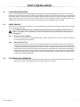
ABOUT THIS MANUAL
This manual provides all the information you will need to understand panel operation, features and functions. If you are familiar
with other security control panels, we recommend that you read this manual at least once to familiarize yourself with panel
features and programming. Please refer to the index for a complete list of this manual's contents.
The following terminology is used throughout this manual:
[ ] = indicates a key on the keypad
[ ] = indicates a key on the keypad must be pressed
= indicates a warning or important note
italic = indicates data that must be entered, reference to a section in the manual, or an example
“SMALL CAPS” = indicates terminals or LEDs that are located on the control panel, keypad, etc.
Programming method used to program
this feature
5.8
Section title
Where the feature is
programmed
Factory default
CALL BACK
Feature Select Programming D Address 086; Key [4]
Default: Call Back Disabled
For additional security, when a PC using the Espload software attempts to communicate with the control panel, the control
panel can hang-up and call the PC back in order to re-verify identification codes and re-establish communication. When the
control panel answers the call, it will verify if the Panel ID and PC Passwords match and if they do, the control panel will
hang-up and call the Espload software back. The Espload software will automatically go into "wait for dial tone", ready to
answer when the control panel calls back. Please note the Computer Telephone Number (see section 5.4 on page 18) must
be programmed in order to use the "Call Back" feature.
Key [4] "OFF": Call Back Disabled
Key [4] "ON": Call Back Enabled
[ENTER] + Installer Code + [10] [8] [6] + [4] ON/OFF + [ENTER] twice
Section
#
1.2
Description of feature
How to program
Option
NEW FEATURES
• Serial or parallel wiring for ATZ connections (page 28)
• New Pager reporting options; Pager Delay (page 24), Pager Format Options (page 24) and Pager Report Event Options
(page 24)
• Auto Test Report Time Option (page 26)
• New on-board green STATUS LED
1.3
SPECIFICATIONS
• Input voltage:
12Vdc
• Current consumption: 50mA maximum
Specifications may change without prior notice
1.4
ABOUT PARADOX
Paradox Security Systems strives to design and manufacture the best security products money could buy. Our products are of
the highest quality standards and most importantly meet the needs and expectations of our customers. By refusing to settle for
the limitations of existing technology, Paradox makes it clear, we are not interested in mirroring the products already on the
market. Breaking down barriers to better technology is what innovation is all about.
The guiding principle behind Paradox research and development has always been to create security products that make sense.
Whether the situation calls for a full range of "intelligent" and easy to use control panels, efficient peripheral security devices, or
"false alarm free" motion or breaking glass detectors. We are putting all our resources into developing products that reflect our
twin philosophies of innovation and user-friendliness. Now we invite you to reap the benefits.
4
REFERENCE & INSTALLATION MANUAL
PART 2: INSTALLATION
2.1
LOCATION AND MOUNTING
Remove the printed circuit board, mounting hardware and keypad from the packaging inside the panel box. The circuit board
should not be mounted into the back of the cabinet, until all cables are pulled into the cabinet and prepared for connection. Before
mounting the cabinet, push the five white nylon-mounting studs into the back of the cabinet. Select an installation site that is not
easily accessible to intruders. Leave at least 2" around the panel box to permit adequate ventilation and heat dissipation. The
installation site should be dry and close to an AC source, ground connection and telephone line connection.
2.2
EARTH GROUND
Connect the zone and dialer ground terminals from the control panel to the metallic enclosure and cold water pipe or grounding
rod as per local electrical codes.
For maximum lightning protection, use separate earth grounds for the zone and dialer grounds as shown in
Figure 2.1 on page 6. For UL installations, the metallic enclosure must be grounded to the cold water pipe or
grounding rod.
2.2.1
AUXILIARY POWER TERMINALS
Connect a 12Vdc power source (external power supply, another control panel, etc.) to the AUX+ and AUX- terminals on
the control panel to power the 708ULT.
2.2.2
KEYPAD FUNCTION TEST
We recommend conducting a "power-up" test on keypads installed far from the control panel. To do so temporarily
connect the keypads near the control panel and apply power. After 10 seconds, begin entering random commands on
the keypad and verify that the keypad "beeps" in response to these commands. Then open a zone to ensure that the
keypad and the control panel are responding to these signals. If the keypad does not respond and indicator lights do
not illuminate, verify that approximately 12Vdc is present at the AUX terminals. If 12Vdc is present, check the keypad
wiring and verify there isn't a short between the black and red keypad wires. If the keypad does not respond, please
contact your local Paradox Distributor.
2.3
TELEPHONE LINE CONNECTION
Connect the incoming telephone company wires into the tip and ring connections of the control panel. Then run the
wires from T-1 and R-1 to the telephone system as shown in Figure 2.1 on page 6.
ESPRIT 708 ULTRA
5
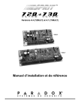
Figure 2.1: 708 Ultra Control Panel PCB Layout
LED:
Flash once every second = normal
Toggle ON for 1 second & OFF for 1 second = trouble
Always ON = panel is using the telephone line
Flashing fast for 4 seconds after power-up = installer lock enabled
STATUS
Reset Jumper
OFF
Warning:
Disconnect the
telephone line
before servicing.
ON
Cold water
pipe or
grounding rod
Please refer to Inset 1 for the zone recognition of the
input terminals. For hardwire connections, Single Zone
Input Terminal Connections on page 9 and Advanced
Technology Zone (ATZ) Connections on page 11.
Ground
clamp
AWG# 14 single conductor solid copper wire.
To metallic
enclosure
UL Note: For UL installations, the metallic
enclosure must be grounded to the cold
water pipe or to the grounding rod.
External power
supply or
another Esprit
control panel
Power the 708 Ultra by connecting a
12Vdc power source to the AUX terminals
of the 708ULT. You can use an external
power supply or the AUX outputs of
another Esprit control panel to power the
708ULT.
6
12Vdc
To provide maximum lightning
protection we strongly recommend
having seperate earth connections
for the dialer and zone ground
terminals.
Keypads
- LED Keypads 636 and 646
- LCD Keypad 642
REFERENCE & INSTALLATION MANUAL
2.4
KEYPAD CONNECTIONS
Connect the four keypad connections labeled RED, BLACK, GREEN and YELLOW to the corresponding terminals on the control panel
as indicated in Figure 2.2 below.
Please note that on some keypads you may have to remove the back panel to make the connections.
Figure 2.2: Keypad and Keyswitch Connections
2.5
KEYPAD ZONE CONNECTIONS
Each keypad comes with one input terminal, allowing you to connect one detector or door contact directly to the keypad.
Example: A door contact located at the entry point of an establishment can be wired directly to the input terminal of the entry point
keypad instead of wiring the door contact all the way to the control panel.
Figure 2.3: Connecting One Keypad Zone
In the control panel, enable Keypad
Supervision at address 090.
Key [11] ON = Keypad Zone 1
LED KEYPADS:
(J1) Zone select jumper OFF
(J2) EOL select jumper ON
642 LCD KEYPADS:
Keypad Programming Mode
Option [2] (Keypad Options); Key [1] ON
Option [2] (Keypad Options); Key [2] ON
Option [2] (Keypad Options); Key [3] OFF
Option [2] (Keypad Options); Key [4] ON
Regardless of the number of keypads in the system, the control panel supports a maximum of two keypad zones. The control
panel will recognize these added zones as shown in Table 1 on page 8.
If using two keypad zones, one keypad must be defined as keypad zone 1 while the other must be defined as keypad
zone 2 (see Figure 2.4 on page 8).
Example: A security installation is comprised of five keypads. Of these five keypads only two can have their zone input terminals
enabled (see Figure 2.4 on page 8). The other three keypads must have their zone input terminals disabled as described
Disabling 636 and 646 Keypad Zones and Disabling 642 Keypad Zones on page 8.
ESPRIT 708 ULTRA
7
Figure 2.4: Connecting Two Keypad Zones Using Two Keypads
In the control panel, enable
keypad supervision at address
090: keys [11] and [12] ON
KEYPAD ZONE 1:
LED KEYPAD:
(J1) Zone select jumper OFF
(J2) EOL select jumper ON
KEYPAD ZONE 2:
LED KEYPAD:
(J1) Zone select jumper ON
(J2) EOL select jumper ON
642 LCD KEYPADS:Keypad programming mode
Option [2] (keypad Options)
keys [1] and [2] ON,
key [3] OFF, key [4] ON
642 LCD KEYPADS:Keypad programming mode
Option [2] (keypad Options)
keys [1] and [2] ON,
keys [3] and [4] ON
Disabling 636 and 646 Keypad Zones
If the keypad zone input terminal is not being used, disable it by shorting the blue zone wire with the black “com” wire of the
keypad.
Disabling 642 Keypad Zones
If the keypad zone input terminal is not being used, disable it by entering the keypad’s programming mode and disabling option
[2] (Keypad Options) key [1] (OFF = keypad zone disabled).
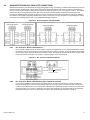
Table 1: Keypad Zone Recognition Table
If using an LED keypad, set the Zone Select Jumper (J1) on the back of the keypad:
Zone Select Jumper J1 OFF = Keypad Zone 1
Zone Select Jumper J1 ON = Keypad Zone 2
If the Zone Select Jumper is changed, the control panel will only recognize the change when
the keypad is disconnected and reconnected.
If using a 642 LCD Keypad, program the keypad definition as follows:
Keypad Programming Mode, option [2] (Keypad Options); Key [1] ON = Keypad zone enabled
Keypad Programming Mode, option [2] (Keypad Options); Key [2] ON = Zone requires 1k9 EOL resistor
Keypad Programming Mode, option [2] (Keypad Options); Key [3] OFF = Keypad Zone 1
Keypad Programming Mode, option [2] (Keypad Options); Key [3] ON = Keypad Zone 2
Keypad Programming Mode, option [2] (Keypad Options); Key [4] ON = Keypad communication supervision
The control panel will display open keypad zones as follows:
ATZ disabled
ATZ enabled
Keypad Zone 1 = Zone 5
Keypad Zone 1 = Zone 9
Keypad Zone 2 = Zone 6
Keypad Zone 2 = Zone 10
8
REFERENCE & INSTALLATION MANUAL
2.6
CONNECTING A TAMPER SWITCH ON AN LED KEYPAD
Figure 2.5: Connecting a Tamper switch on a Keypad
LED
LED
Once the keypad zones have been defined you must enable Keypad Zone Supervision (see section 7.5 on page 28 and section
7.6 on page 28) in the control panel.
2.7
SINGLE ZONE INPUT TERMINAL CONNECTIONS
The system hardware recognizes the following single zone input terminal connections. For more information on programming the
options mentioned below see ZONE DEFINITIONS on page 27.
2.7.1
N.C. CONTACTS, WITHOUT EOL RESISTOR
If your security installation does not require tamper or wire fault detection, connect the detection devices and program
the control panel as shown in Figure 2.6 on page 9. This setup will communicate an open or closed zone to the control
panel, displaying open zones on the keypad. Do not use devices with N.O. contacts in this setup, as this will cause the
control panel to remain in alarm.
Figure 2.6: N.C. Contacts, without EOL Resistor
Address 088, [MEM] = ON (EOL resistor disabled)
[10] = OFF
Tamper/Wire Fault disabled.
[11] = OFF
Address 090, [8] = OFF (ATZ disabled)
2.7.2
N.O. AND N.C. CONTACTS, WITH EOL RESISTOR (UL/ULC)
If your security installation does not require tamper or wire fault recognition but some detection devices will use
normally open contacts. Connect all detection devices using a 1k9 end of line (EOL) resistor and program the control
panel as shown in Figure 2.7 on page 10. This setup will communicate an open or closed zone to the control panel,
displaying open zones on the keypad.
ESPRIT 708 ULTRA
9
Figure 2.7: N.O. and N.C. Contacts, with EOL Resistor (UL/ULC)
Address 088, [MEM] = OFF (EOL resistor enabled)
[10] = OFF
Tamper/Wire Fault disabled.
[11] = OFF
Address 090, [8] = OFF (ATZ disabled)
UL/ULC Configuration
2.7.3
N.C. CONTACTS, WITHOUT EOL RESISTOR, WITH TAMPER RECOGNITION
If your security installation requires tamper recognition, all detection devices must use normally closed contacts.
Connect the devices and program the control panel as shown in Figure 2.8 below. This setup will communicate an
open or closed zone to the control panel, displaying open zones on the keypad. The control panel will also
communicate any detected tampers (cuts) as per Tamper / Wire Fault Recognition Options on page 30 (section 8.6).
Figure 2.8: N.C. Contacts, without EOL Resistor, with Tamper Recognition
Address 088, [MEM] = ON (EOL resistor disabled)
[10] =
Refer to section 8.6 on page 30.
[11] =
Address 090, [8] = OFF (ATZ disabled)
2.7.4
N.C. CONTACTS, WITH EOL RESISTOR, WITH TAMPER AND WIRE FAULT RECOGNITION (UL/ULC)
If your security installation requires tamper (cut) and wire fault (short) recognition, all detection devices must use
normally closed contacts. Connect the devices and program the control panel as shown in Figure 2.9 below. This
setup will communicate an open or closed zone to the control panel, displaying open zones on the keypad. The control
panel will also communicate any detected tampers (cuts) and/or wire faults (short) as per Tamper / Wire Fault
Recognition Options on page 30.
Figure 2.9: N.C. Contacts, with EOL Resistor, with Tamper and Wire Fault Recognition (UL/ULC)
Address 088, [MEM] = OFF (EOL resistor enabled)
[10] =
Refer to section 8.6 on page 30.
[11] =
Address 090, [8] = OFF (ATZ disabled)
10
REFERENCE & INSTALLATION MANUAL
2.8
ADVANCED TECHNOLOGY ZONE (ATZ) CONNECTIONS
Enabling the ATZ feature (see Advanced Technology Zoning (ATZ) on page 27) allows you install two detection devices per input
terminal, therefore, doubling zone capacity of the control panel. Advanced Technology Zoning is a software-oriented feature,
there is no need for extra modules, simply install the devices as shown in Figures 2.11 to 2.14 on pages 11 and 12. The 708ULT
employs two ways of wiring ATZ connections, ATZ series connection and ATZ parallel connection. The control panel will
recognize the installed devices as shown in Figure 2.10 below. The extra zones function exactly like any other zone displaying
zone status on the keypad and sending separate alarm codes for each zone. For more information on programming the options
mentioned in the following sections refer to see ZONE DEFINITIONS on page 27.
Figure 2.10: Zone Recognition with ATZ Enabled
2.8.1
N.C. CONTACTS, WITHOUT EOL RESISTOR
If your security installation does not require tamper or wire fault recognition but you are using the ATZ feature, connect
the detection devices and program the control panel as shown in Figure 2.11 below. Do not use devices with normally
open contacts, as this will cause the system to remain in alarm. This setup will communicate the status of each device
to the control panel (see Figure 2.10 on page 11), displaying open zones on the keypad.
Figure 2.11: N.C. Contacts, without EOL Resistor
Address 088, [MEM] = ON (EOL resistor disabled)
[10] = OFF
Tamper/Wire Fault disabled.
[11] = OFF
Address 090, [7] = OFF (ATZ wiring in series)
[8] = ON (ATZ enabled)
2.8.2
N.C. CONTACTS, WITHOUT EOL RESISTOR, WITH TAMPER RECOGNITION
If your security installation requires tamper recognition and you are using the ATZ feature, connect the detection
devices and program the control panel as shown in Figure 2.12 on page 12. Do not use devices with normally open
contacts, as this will cause the zone to remain open. This setup will communicate the status of each zone to the control
panel (see Figure 2.10 on page 11), displaying open zones on the keypad. The control panel will also communicate
any detected tampers (cuts) on the system as per Tamper / Wire Fault Recognition Options on page 30.
ESPRIT 708 ULTRA
11
Figure 2.12: N.C. Contacts, without EOL Resistor, with Tamper Recognition
Address 088, [MEM] = ON (EOL resistor disabled)
[10] =
Refer to section 8.6 on page 30.
[11] =
Address 090, [7] = OFF (ATZ wiring in series)
[8] = ON (ATZ enabled)
2.8.3
N.C. CONTACTS, WITH EOL RESISTOR, WITH TAMPER & WIRE FAULT RECOGNITION (UL/ULC)
If your system requires tamper (cut) and wire fault (short) recognition, connect two detection devices to one input
terminal with a 1k9 end of line (EOL) resistor and program the control panel as shown in Figure 2.13 below. Do not
use devices with normally open contacts, this will cause the zone to remain open. This setup will communicate the
status of each zone to the control panel (see Figure 2.13 on page 12), displaying open zones on the keypad. Any
tampers (cuts) and/or wire fault (shorts) detected on the system are communicated as per Tamper / Wire Fault
Recognition Options on page 30.
Figure 2.13: N.C. Contacts, with EOL Resistor, with Tamper and Wire Fault Recognition (UL/ULC)
Address 088, [MEM] = OFF (EOL resistor enabled)
[10] =
Refer to section 8.6 on page 30.
[11] =
Address 090, [7] = OFF (ATZ wiring in series)
[8] = ON (ATZ enabled)
2.8.4
ATZ PARALLEL WIRING
If your security installation does not require tamper or wire fault recognition but requires the connection of two
detection devices to one input to be in parallel, connect the devices and program the control panel as shown in Figure
2.14 below. Do not use devices with normally open contacts as this will cause the zone to remain open. This setup will
communicate the status of each zone to the control panel, displaying open zones on the keypad. For more information,
see ATZ Parallel Wiring on page 28.
Figure 2.14: ATZ Parallel Wiring
Address 088, [MEM] = OFF (EOL resistor enabled)
[10] = OFF
Tamper/Wire Fault disabled
[11] = OFF
Address 090, [7] = ON (ATZ wiring in parallel)
[8] = ON (ATZ enabled)
Address 090, key [7] (page 28) must be ON in order to connect the zones in parallel.
12
REFERENCE & INSTALLATION MANUAL
PART 3: ACCESS CODES
3.1
INSTALLER CODE
Streamline - Section 00 D Hexa Programming - Addresses 000 to 002
Default: 080808
Only the installer code allows you to program all control panel settings. To program any setting in the control panel you must
enter the programming mode by pressing the [ENTER] key followed by the installer code. The installer code contains six digits and
each digit can be any value from 0 to 9. To change the installer code press:
[ENTER] + Installer Code + [10] [10] [10] + First 2 digits + [10] [10] [1] + Next 2 digits + [10] [10] [2] + Final 2 digits + [ENTER]
3.2
INSTALLER LOCK
Decimal Programming D Address 058
Default: Address Empty
Program 147 into address 058 to lock all programming. When the installer lock is enabled, the STATUS LED will flash and the
dialer relay will make a clicking noise (made by the relay opening and closing) for 4 seconds during power up. Hence, performing
a hardware reset (see Power Down Reset on page 30) will not affect the current settings. To remove the installer lock, enter any
value besides 147.
[ENTER] + Installer Code + [10] [5] [8] + [1] [4] [7] + [ENTER]
ESPRIT 708 ULTRA
13
PART 4: PROGRAMMING METHODS
The 708 Ultra control panels can be programmed using either the keypad or the Espload Software (V3.0 or higher). We highly
recommend programming the control panels using the Espload Software, as it simplifies the process and reduces the potential of
data entry errors. You can also program the control panels manually by using a keypad.
4.1
ESPLOAD SOFTWARE
With the Espload Software (V3.0 or higher), you can program the 708 Ultra control panels remotely via modem or locally using an
ADP-1 adapter. The advanced Espload software can execute fast uploads or downloads and provides many powerful features.
These include a comprehensive "monitoring" mode to oversee all panel activity, a "scheduler" to initiate pre-programmed tasks at
set intervals, and a "batch" mode to carry out pre-programmed tasks following a call from the control panel. Using Espload there
is no limit to the number of account files or panel defaults created. Espload can also be converted to the language of your choice.
Contact your local Paradox Distributor for your free copy of the Espload software.
4.2
KEYPAD
When programming, use the supplied "Programming Guide" to keep track of which addresses were programmed and how.
Before programming the control panel, we recommend you read this manual in order to acquire a good understanding of the
control panel and its features. When programming with the keypad, certain addresses are programmed using different methods.
These methods are described in detail below. Each section in this manual will reference the appropriate programming method.
4.2.1
HEXA PROGRAMMING
Addresses 000 to 043 and 300 to 527 are programmed using the Hexa Programming method. In this mode, you can
enter any hexa-digit from 0 to F where keys [1] to [9] represent digits 1 to 9 respectively; the other keys represent
hexa-digits A to F as shown in Figure 4.1. To program using the Hexa Programming method:
Press [ENTER] + Installer Code.
The [ENTER] key will flash indicating you are in programming mode.
Enter the desired 3-digit address.
The keypad will display the 2-digit data currently saved at this address as described in Figure 4.1.
Enter 2-digit data; after entering data you do not need to press enter, the software will automatically save the data
into the selected address.
6. Return to step 2 to continue programming or press [CLEAR] to exit programming mode.
1.
2.
3.
4.
5.
14
REFERENCE & INSTALLATION MANUAL
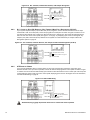
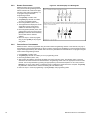
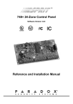
Figure 4.1: Hexa Programming
Hexa Digit Data Display for LED Keypads
Note: LCD keypads will display current data on the screen.
If the key is not lit, value = 0
Sum of the first row = second hexa digit
Sum of the second row = first hexa digit
Each key in the first 2 rows of the keypad represents a specific value when the
key is lit, as shown above. If the key isn’t lit, the key represents 0. The sum of the
values of the lit keys in the first row correspond to the second hexa digit. The
sum of the values of the lit keys in the second row correspond to the first hexa
digit as shown in the example below.
= Second digit = 8 + 2 = 10
= First digit = 4 + 2 + 1 = 7
Therefore 2-digit data = 7A
Note: Values 10 to 15 represent hexa digits A to F respectively. See the
keypads at left.
4.2.2
HEXA STREAMLINED SECTION PROGRAMMING
This is an alternate method to Hexa Programming. The addresses (000 to 043 and 300 to 527) programmed in the
Hexa Programming method are grouped into 67 sections where each section contains four addresses (i.e. section 00
= addresses 000 to 003). Using this method allows you to program 8 digits (4 addresses) without having to exit and reenter addresses. When entering the final digit, the software will automatically advance to the next section.
Example: If you complete the "Programming Guide" with the desired data, you can program the 68 sections by
entering all digits without pressing [ENTER] or entering any other addresses. This greatly reduces programming time.
Note: the keypad will not display the current data in the Hexa Streamlined Programming method. To program
using the Hexa Streamlined Section method:
1. Press [ENTER] + Installer code + [7].
2. The [ENTER] and [2ND] keys will flash to indicate you are in streamlined programming mode.
3. Enter 2-digit section (00 to 67).
4. The [ENTER] key will remain on and the [2ND] key will turn off.
5. Enter 8-digit data to program the section.
6. The keypad will "beep" to indicate that the section has been programmed, data is saved and the software has
advanced to the next section.
7. Return to step 4 to continue programming or press [CLEAR] to exit programming mode.
ESPRIT 708 ULTRA
15
4.2.3
DECIMAL PROGRAMMING
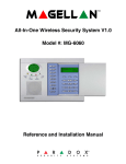
Figure 4.2: Decimal Display For LED Keypads
Addresses 044 to 061 are programmed
using the Decimal Programming method.
Values entered must contain three digits
from 000 to 255 (where the [10] key = 0).
To program using the Decimal
Programming method:
1. Press [ENTER] + Installer Code.
2. The [ENTER] key will flash to indicate
you are in programming mode.
3. Enter 3-digit address (044 to 061).
4. The keypad will now display the current
3-digit data currently saved at this
address as described in Figure 4.2.
5. Enter 3-digit data (decimal) value; after
entering data you do not need to press
[ENTER], the software will automatically
save the data into the selected
address.
6. Return to step 2 to continue programming or press [CLEAR] to exit programming mode.
4.2.4
FEATURE SELECT PROGRAMMING
Addresses 062 to 126 are programmed using the Feature Select Programming method. In this method, every key in
each address on the keypad represents an option or feature. Pressing a key will display it on the keypad and pressing
it again will extinguish the key. The ON/OFF status of each key determines the selected feature. To program using the
Feature Select Programming method:
Press [ENTER] + Installer Code.
The [ENTER] key will flash to indicate you are in programming mode.
Enter 3-digit address (062 to 126).
After entering the address, the keypad will display the feature selection status. The ON/OFF status of the keys
determines the selected features as described in the "Programming Guide" and in the appropriate sections of this
manual. Turn the keys ON/OFF by pressing the appropriate key until the desired options are set. Then press the
[ENTER] key to accept, there will be a confirmation "beep" indicating the options have been accepted. The [ENTER]
key will flash to indicate that the software is awaiting the next address entry.
5. Return to step 3 to continue programming or press [CLEAR] to exit programming mode.
1.
2.
3.
4.
16
REFERENCE & INSTALLATION MANUAL
PART 5: PANEL SETTINGS FOR ESPLOAD
5.1
PANEL ANSWER OPTIONS
Streamline - Section 00 D Hexa Programming - Address 003
Default: Answering Machine Override Disabled; Number of Rings = 8
The following two options will define how the control panels answer an incoming call from a computer using Espload.
In order for the Espload software to remotely communicate with the control panel, call the installation site twice using the Espload
Software. To do so, program the first digit in address 003 with any value from 1 to F (see Table 2 on page 17), this value
represents the delay period the control panel will wait between the first and second call. Using the Espload software, call the
installation site and on the second ring press [ENTER] on the keyboard to hang-up. After hanging up, the Espload software will
wait 10 seconds before calling the installation site back. If the installation site is called back within the programmed delay period,
the control panel will override the answering machine or service by picking-up on the first ring. To disable this option program
[2ND] or [1] as the first digit in address 003.
Example: A security installation is using an answering machine set to answer after 3 rings, the first digit at address 003 has been
programmed with 5 (40 sec.) and the second digit has been programmed with 8. When you call the installation site with the Espload
software the first time, wait two rings and press [ENTER] on the keyboard. The Espload software will wait 10 seconds before calling
the installation site back. If the second call is made within 40 seconds, the panel will pick up the line on the first ring. If it takes more
than 40 seconds, the panel will not answer on the first ring and the answering machine will answer after three rings.
Table 2: Answering Machine Override Options
[2ND] or [1] = Answering Machine Override disabled
[2] = 16 seconds
[4] = 32 seconds
[3] = 24 seconds
[5] = 40 seconds
[6] = 48 seconds
[7] = 56 seconds
[8] to [F] = 60 seconds
[ENTER] + Installer Code + [10] [10] [3] + 1st digit + 2nd digit (1 to 15 rings) + [ENTER]
The second digit represents the number of rings the control panel will wait before picking-up the line. If the line is not answered
after the number of re-programmed rings, the control panel will answer the call. Note the control panel resets the "ring" counter
every 64 seconds. Therefore, if someone or an answering machine answers a call before the number of pre-programmed rings
has elapsed, the control panel will keep the number of rings in memory for 64 seconds. If you hang-up and call the installation site
back within 64 seconds, the control panel will continue to count the number of rings from the first call. After reaching the total
number of rings, the control panel will answer the call. The number of rings can be set from 1 to 15 by programming the second
digit at address 003 with any hexa-digit from 1 to F. Program the second digit with [2ND] to disable this option.
Example: Address 003 = [2ND] [8]. Using the Espload software, you call an installation site where there is no answering machine
or service and no one is home. Since there is no one to answer the telephone call, the control panel will pick-up the line on the
eighth ring. If someone happens to be home and answers the telephone, say, after three rings, the control panel will keep the
three rings in memory for 64 seconds. If you hang-up and call back the installation site within 64 seconds the control panel will
answer the call on the fifth ring. If you call back after 64 seconds the "ring" counter will have been reset and the control panel will
answer the call on the eighth ring.
If you program four or less rings, the control panel will always reset the “ring” counter.
5.2
PANEL IDENTIFIER
Streamline - Section 01 D Hexa Programming - Addresses 004 and 005
This four-digit code identifies the control panel to the Espload software before initiating upload. Program the same 4-digit code
into the control panel and the Espload software before attempting to establish communication. If the codes do not match, the
control panel will not establish communication. Enter any hexa digits from 0 to F.
[ENTER] + Installer Code + [10] [10] [4] + First 2 digits + [10] [10] [5] + Final 2 digits + [ENTER]
5.3
PC PASSWORD
Streamline - Section 01 D Hexa Programming - Addresses 006 and 007
This four-digit download password identifies the PC to the panel, before beginning the download process. Enter the same
password into the Espload software and the control panel. If the passwords are not the same, Espload will not establish
communication. Enter any hexa digits from 0 to F.
[ENTER] + Installer Code + [10] [10] [6] + First 2 digits + [10] [10] [7] + Final 2 digits + [ENTER]
ESPRIT 708 ULTRA
17
5.4
COMPUTER TELEPHONE NUMBER
Streamline Section 02 and 03 D Hexa Programming - Address 008 to 015
The control panel will dial this telephone number when trying to initiate communication with the PC (see Call Espload below).
There is no default telephone number and you can enter any number from 0 to 9 up to a maximum of 16 digits. If you would like
to enter any special keys or functions refer to Table 4 on page 21. If the telephone number contains less than 16 digits, press the
[TBL] / [TRBL] key to indicate the end of the telephone number.
[ENTER] + Installer Code + [7] + [10] [2] + Telephone Number (if less than 16 digits press [TBL] / [TRBL]) + [ENTER]
5.5
CALL ESPLOAD
Key Access Programming D key [TBL] / [TRBL]
The control panel will dial the telephone number entered at addresses 008 to 015 (see Computer Telephone Number above) in
order to communicate with the Espload software. The control panel and the computer will verify that the Panel Identifier and the
PC Password match before establishing communication (see section 5.2 and section 5.3 on page 17).
Press [ENTER] + Installer Code + [TBL] / [TRBL]
5.6
ANSWER ESPLOAD
Key Access Programming D Key [AWAY] / [FORCE]
By entering the code sequence listed below, you can manually force the control panel to answer any incoming calls from the
Espload software. This option can also be used to perform an on-site upload/download by connecting your computer directly to
the control panel using an ADP-1 line adapter and manually answering Espload from the control panel. In Espload go to:
Main Menu D Program Setup D Modem and Printer Configuration
Set "Dialing Condition" to "Blind Dial". Program the panel telephone number in Espload and follow the instructions on the ADP-1
adapter. When the computer has dialed press:
[ENTER] + Installer Code + [AWAY] / [FORCE]
5.7
CANCEL COMMUNICATION
Key Access Programming D Key [STAY]
Use the Installer Code to cancel all communication and erase any unreported events in the buffer until the next reportable event.
[ENTER] + Installer Code + [STAY]
5.8
CALL BACK
Feature Select Programming D Address 086; Key [4]
Default: Call Back Disabled
For additional security, when a PC using the Espload software attempts to communicate with the control panel, the control panel
can hang-up and call the PC back in order to re-verify identification codes and re-establish communication. When the control
panel answers the call, it will verify if the Panel ID and PC Passwords match and if they do, the control panel will hang-up and call
the Espload software back. The Espload software will automatically go into "wait for dial tone", ready to answer when the control
panel calls back. Please note the Computer Telephone Number (see Computer Telephone Number above) must be programmed
in order to use the "Call Back" feature.
Key [4] "OFF": Call Back Disabled
Key [4] "ON": Call Back Enabled
[ENTER] + Installer Code + [10] [8] [6] + [4] ON/OFF + [ENTER] twice
18
REFERENCE & INSTALLATION MANUAL
PART 6: EVENT REPORTING
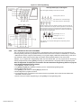
Figure 6.1: Event Reporting
Central Station Telephone Number #1
Sections 04 & 05; Addresses 016 to 023
Phone Number
Central Station Telephone Number #2
Sections 06 & 07; Addresses 024 to 031
Control panel will never
transmit report codes
Disabled
OFF/OFF
Reporting
Events
RELATED FEATURES
Alternate between the two Central
Station Numbers until communication is
achieved beginning with Central #1
Regular
OFF/ON
When system is in alarm, Central
Station Telephone #1 will be dialed until
communication is achieved
Reporting Options
Address 086
Keys [11] & [12]
Auto Test Report
Addresses 046 to 048
Manual Test Report
[BYP] Key Access
Report Zone Restore Options
Address 088; [BYP]
Split
ON/OFF
When system is not in alarm, Central
Station Telephone #2 will be dialed until
communication is achieved
Doubled
ON/ON
Will send the report code to both
Central Stations starting with Central #1
[2ND] = Ademco Slow
[2] = Silent Knight Fast
Pulse
[3] = SESCOA
[4] to [7] = Radionics
Valid report codes must be
programmed into the addresses
corresponding to the reportable
events
Section 11 to 67
[1] = 1400Hz to 1800Hz
Communication
Format
Address 038
1st digit = Central 1
2nd digit = Central 2
Addresses 300 to 527
[8] = Ademco Express
[10] = Ademco Contact I.D.
(all codes)
DTMF
(Tone)
Addresses 300 to 527 do not need to be
programmed
[9] = Ademco Contact I.D.
Programmable
[TRBL] = Pager
6.1
Valid codes corresponding to the Contact I.D.
table (Table 7 on page 23) must be
programmed in the addresses corresponding
to the reportable events
REPORTING OPTIONS
Feature Select Programming D Address 086; Keys [11] and [12]
Default: Reporting Disabled
When a specific event occurs in the system, the control panel will attempt to report the appropriate event code (if programmed) to
the Central Station. The four available Reporting Options described in the table below, define where the event codes are
reported. In order to establish communication with the Central Station the control panel will first access a telephone line and wait
a maximum of 8 seconds for a dial tone. If a dial tone is recognized or if after 8 seconds there is no dial tone, the control panel will
dial the appropriate Central Station Telephone Number as defined by the Reporting Options listed in the table below. If
communication is established, the control panel will transmit the events in the event buffer to the Central Station. If
communication fails during transmission, the control panel will dial the next central station telephone number, as defined by the
reporting options listed below, and report only those events not reported during the interrupted attempt. For information on
Reporting Event Codes see section 6.9 on page 24.
ESPRIT 708 ULTRA
19
[ENTER] + Installer Code + [10] [8] [6] + [11] and [12] ON/OFF + [ENTER]
Table 3: Reporting Options
Key [11]
OFF
OFF
ON
ON
6.1.1
Key [12]
OFF
ON
OFF
ON
Reporting Feature
Reporting Disabled
Regular Reporting
Split Reporting
Double Reporting
REPORTING DISABLED
The Control Panel will never transmit any event codes to the central station.
6.1.2
REGULAR REPORTING
Using regular reporting the event codes are reported to the central station using either telephone number 1 or 2. The
control panel will begin by dialing central station telephone number 1. If communication fails, the dialer will hang up,
wait a predetermined period and dial central station telephone number 2. This sequence will repeat 4 times, switching
back and forth between the 1st and 2nd number (see Figure 6.2 on page 21) until communication is established. After
eight unsuccessful attempts, the redial sequence ends and a "communicator report failure" will appear in the keypad's
trouble display (key [7] "ON"). When the next event occurs (reportable or non-reportable), the control panel will begin
the dialing sequence again.
6.1.3
SPLIT REPORTING
When the system is in standby, the control panel will report all Event Codes to Central Station Telephone 2. If
communication fails, the dialer will hang-up, wait a predetermined period and dial the number again. The control panel
will dial the number eight times until communication is established (see Figure 6.2 on page 21). After eight
unsuccessful attempts, the redial sequence ends and a "communicator report failure" will appear in the keypad's
trouble display (key [7] "ON"). When the next event occurs (reportable or non-reportable), the control panel will begin
the dialing sequence again.
When the system is transmitting an alarm call, the control panel will report all Event Codes to Central Station
Telephone 1. Any ongoing communication (upload/download or reporting to Telephone 2) will stop immediately and
the panel will dial Telephone 1. If communication fails, the dialer will hang-up, wait a predetermined period and dial the
number again. The control panel will dial the number eight times until communication is established (see Figure 6.2 on
page 21). After eight unsuccessful attempts, the redial sequence ends and a "communicator report failure" will appear
in the keypad's trouble display (key [7] "ON"). When the next event occurs (reportable or non-reportable), the control
panel will begin the dialing sequence again.
6.1.4
DOUBLE REPORTING
In double reporting, the control panel will report each event code to both central station telephone numbers. The
control panel will begin by attempting communication with central station telephone 1 and if communication fails, the
dialer will hang-up, wait a predetermined period and dial the number again. The control panel will dial the number eight
times until communication is established (see Figure 6.2 on page 21). After eight unsuccessful attempts, the redial
sequence ends and a "communicator report failure" will appear in the keypad's trouble display (key [7] "ON"). If
communication has been established and the event codes transmitted or if after eight attempts communication has not
been established, the control panel will report the same Event Codes to Central Station Telephone 2.
20
REFERENCE & INSTALLATION MANUAL
Figure 6.2: Reporting Options
6.2
CENTRAL STATION TELEPHONE NUMBER 1
Streamline - Section 04 and 05 D Hexa Programming - Addresses 016 to 023
The control panel will dial the programmed telephone number when reporting an event code to the central station computer (see
Reporting Options on page 19). For example, when a zone with a motion detector opens, the control panel may dial the
telephone number in order to send the programmed event code to the central station computer. There is no default telephone
number and you can enter any number from 0 to 9 up to a maximum of 16 digits. If you would like to enter any special keys or
functions, refer to Table 4 below. If the telephone number contains less than 16 digits, press the [TBL] / [TRBL] key to indicate the
end of the telephone number.
[ENTER] + Installer Code + [7] + [10] [4] + Telephone Number + [ENTER] or [TBL] / [TRBL] if number is less than 16 digits
6.3
CENTRAL STATION TELEPHONE NUMBER 2
Streamline - Section 06 and 07 D Hexa Programming - Addresses 024 to 031
The control panel can communicate with two central station numbers. The control panel may at times dial the second number
depending on the selected Reporting Options (see section 6.1 on page 19). If the central station does not have a second number,
you must enter the same number as the first. There is no default telephone number and you can enter any number from 0 to 9 up
to a maximum of 16 digits. If you would like to enter any special keys or functions refer to Table 4 below. If the telephone number
contains less than 16 digits, press the [TBL] / [TRBL] key to indicate the end of the telephone number.
[ENTER] + Installer Code + [7] + [10] [6] + Telephone Number + [ENTER] or [TBL] / [TRBL] if number is less than 16 digits
Table 4: Telephone Number Special Instruction
Enter special instructions in the telephone numbers using these keys:
= switch from pulse to tone while dialing
[10]
= the number “0”
[BYP]
[MEM]
= pause 4 seconds
[11] / [STAY] = *
[TBL] / [TRBL] = end of telephone number
[12] / [FORCE] = #
Both Central Station Telephone Numbers must be programmed in order for event reporting to function properly.
ESPRIT 708 ULTRA
21
6.4
SYSTEM ACCOUNT CODES
Streamline - Section 08 D Hexa Programming - Addresses 032 to 035
All report codes are preceded by a 3- or 4-digit system account code to ensure correct identification to the central station,
identifying from which security system the event originated. For example, if a zone opens, the control panel will first send the
account code followed by the appropriate report code.
Program the same value for both account numbers.
There are no defaults and you can enter any hexa digit from 0 to F. Please note if required, system account codes can have 3
digits. To do so, press the [2ND] key followed by the 3-digit account number.
[ENTER] + Installer Code + [7] + [10] [8] + 4-digit Account Code #1 + 4-digit Account Code #2 + [ENTER]
[ENTER] + Installer Code + [7] + [10] [8] + [2ND] + 3-digit Account Code #1 + [2ND] 3-digit Account Code #2 + [ENTER]
6.5
COMMUNICATOR FORMATS
Streamline - Section 09 D Hexa Programming - Address 038
Default: Ademco Slow for both numbers
The following option will determine which format the control panel will use to communicate with the Central Station. You can
select a different communicator format for each Central Station Telephone Number. Using Table 5, select the appropriate
communication format. The first digit represents the Communication Format for Central Station Telephone Number 1 and the
second digit represents the Communication Format for Central Station Telephone Number 2. Below you will find a brief
description of all available Communicator Formats.
[ENTER] + Installer Code + [10] [3] [8] + First digit = (Central Station Telephone #1) + Second digit = (Central Station Telephone
#2) + [ENTER]
Table 5: Communicator Formats
Key
[2nd]
[1]
[2]
[3]
[4]
[5]
= ADEMCO slow (1400Hz, 1900Hz, 10bps)
= (1400Hz, 1800Hz, 10bps)
= SILENT KNIGHT fast (1400Hz, 1900Hz, 20bps)
= SESCOA (2300Hz, 1800Hz, 20bps)
= RADIONICS (40Bps with 1400Hz handshake)
= RADIONICS (40Bps with 2300Hz handshake)
Key
[6]
[7]
[8]
[9]
[10]
[TBL] / [TRBL]
= RADIONICS with PARITY (1400Hz, 40Bps)
= RADIONICS with PARITY (2300Hz, 40Bps)
= * ADEMCO express
= * ADEMCO contact ID (programmable codes)
= * ADEMCO contact ID (all codes)
= * PAGER FORMAT - (personal dialing)
* = 4-digit account codes only
6.5.1
ADEMCO CONTACT ID (ALL CODES)
Please note that this format must use a 4-digit system account code (see section 6.4 on page 22). Ademco Contact ID
is a fast communicator format that uses tone transmission instead of pulse transmission. This communicator format
also uses a pre-defined list of industry standard messages and event codes that should suit most of your basic
installation needs. Using the "All Codes" format, the control panel will automatically generate the Contact ID event
codes (see Table 6 below) for every event in addresses 300 to 527. Therefore, you do not need to program addresses
300 to 527.
Table 6: Contact ID Event Codes
SYSTEM EVENT
Contact ID Message
Contact ID Code #
400 to 447
Burglary Zone #
130
Zone Tamper
472 to 495
Sensor Tamper
383
Zone Tamper Reset
Timer Loss / Timer Programmed
22
Event Code Addresses
Alarms / Restores
510
501 and 509
Sensor Tamper
383
Time / Date Reset
625
351
TLM Trouble Restore
511
Telco 1 Fault
Test Report
512
Periodic Test
602
Espload Log-In
524
Remote Access
410
Program Change
525
Program Changed
306
REFERENCE & INSTALLATION MANUAL
6.5.2
ADEMCO CONTACT ID (PROGRAMMABLE CODES)
Please note that this format must use a 4-digit system account code (see section 6.4 on page 22). Ademco Contact ID
is a fast communicator format that uses tone transmission instead of pulse transmission. Use the Ademco Contact
event list of industry standard messages and event codes found in Table 7 on page 23 to program the desired event
codes into addresses 300 to 527.
Enter FF to program the default Ademco Contact ID report code when using the Ademco Contact ID (programmable
codes) report format.
Table 7: Programmable Contact ID Event Codes
All addresses from 300 to 527 (sections 11 to 67) programmed with values other than [2ND] [2ND] will report the contact ID
codes corresponding to the values programmed. Values to be programmed should be selected from this table.
CID Reporting Code
Prog. Value
CID Reporting Code
Prog. Value
100: AUXILIARY ALARM
[2ND] / [1]
300: SYSTEM TROUBLE
[2] / [2]
[2ND] / [2]
301: AC LOSS
[2] / [3]
110: FIRE ALARM
111: FIRE SMOKE
[2ND] / [3]
302: LOW SYSTEM BATTERY
[2] / [4]
112: COMBUSTION
[2ND] / [4]
305: SYSTEM RESET
[2] / [5]
[2ND] / [5]
306: PROGRAM CHANGED
[2] / [6]
113: WATER FLOW
114: HEAT
[2ND] / [6]
309: BATTERY TEST FAIL
[2] / [7]
115: PULLSTATION
[2ND] / [7]
320: SOUNDER/RELAY TROUBLE
[2] / [8]
[2ND] / [8]
321: BELL 1 TROUBLE
[2] / [9]
116: DUCT
117: FLAME
[2ND] / [9]
323: ALARM RELAY TROUBLE
[2] / [10]
118: NEAR ALARM
[2ND] / [10]
350: COMMUNICATION TROUBLE
[2] / [11]
[2ND] / [11]
351: TELCO 1 FAULT
[2] / [12]
120: PANIC ALARM
121: DURESS
[2ND] / [12]
354: FAIL TO COMMUNICATE
[2] / [BYP]
122: SILENT PANIC
[2ND] / [BYP]
370: PROTECTION LOOP TROUBLE
[2] / [MEM]
[2ND] / [MEM]
371: PROTECTION LOOP OPEN
[2] / [TRBL]
123: AUDIBLE PANIC
130: BURGLARY
[2ND] / [TRBL]
372: PROTECTION LOOP SHORT
[3] / [2ND]
131: PERIMETER BURGLARY
[1] / [2ND]
373: FIRE LOOP TROUBLE
[3] / [1]
[1] / [1]
382: SENSOR TROUBLE
[3] / [2]
132: INTERIOR BURGLARY
133: 24HR BURGLARY
[1] / [2]
383: SENSOR TAMPER
[3] / [3]
136: BURGLARY OUTDOOR
[1] / [3]
400: OPEN / CLOSE
[3] / [4]
[1] / [4]
401: OPEN / CLOSE BY USER #
[3] / [5]
137: BURGLARY TAMPER
138: BURGLARY NEAR ALARM
[1] / [5]
402: GROUP OPEN / CLOSE
[3] / [6]
140: GENERAL ALARM
[1] / [6]
403: AUTOMATIC OPENING / CLOSING [3] / [7]
[1] / [7]
404: LATE TO OPEN / CLOSE
[3] / [8]
150: 24 HOUR AUXILIARY
151: GAS DETECTED
[1] / [8]
407: REMOTE ARM DOWNLOAD
[3] / [9]
152: REFRIGERATION
[1] / [9]
410: REMOTE ACCESS
[3] / [10]
[1] / [10]
441: OPEN / CLOSE - STAY MODE
[3] / [11]
153: LOSS OF HEAT
154: WATER LEAKAGE
[1] / [11]
570: BYPASS
[3] / [12]
155: FOIL BREAK ALARM
[1] / [12]
572: 24 HOUR ZONE BYPASS
[3] / [BYP]
[1] / [BYP]
573: BURGLARY BYPASS #
[3] / [MEM]
156: DAY TROUBLE ALARM
157: LOW GAS LEVEL
[1] / [MEM]
574: GROUP BYPASS
[3] / [TRBL]
[1] / [TRBL]
601: MANUAL TEST
[4] / [2ND]
158: HIGH TEMPERATURE
[2] / [2ND]
602: PERIODIC TEST
[4] / [1]
159: LOW TEMPERATURE
161: LOSS AIR FLOW
[2] / [1]
625: TIME / DATE RESET
[4] / [2]
654: SYSTEM INACTIVITY
[4] / [3]
6.5.3
ADEMCO EXPRESS
This high-speed reporting format communicates 2-digit (00 to FF) events programmed at addresses 300 to 527 at a
speed of 2 seconds per event. Unlike other Ademco formats, the Contact ID Event Codes are not used. Please note
this format must use a 4-digit system account code (see section 6.4 on page 22).
6.5.4
PAGER REPORTING FORMAT
Using this format allows the control panel to transmit report codes to a pager or a cellular telephone. Since the control
panel cannot confirm whether the transmission was successful or not (no handshake), after dialing, it can be
programmed to transmit data to the pager or cellular telephone immediately or transmit data after a programmed pager
delay has elapsed (section 6.6 on page 24). The account number and the report code are included with each call. For
more information, see section 6.7 on page 24 and section 6.8 on page 24. Use the Ademco Contact event list of
industry standard messages and event codes found in Table 7 on page 23 to program the desired event codes into
addresses 300 to 527.
ESPRIT 708 ULTRA
23
Enter FF to program the default Ademco Contact ID report code when using the Pager report format.
6.5.5
STANDARD PULSE FORMATS
The control panel supports the following pulse reporting formats (see Table 5 on page 22): Ademco slow, Silent
Knight, Sescoa, and Radionics.
6.6
PAGER DELAY
Streamline - Sections 09 D Hexa Programming - Address 037 (1st Digit)
When using the Pager Reporting Format (see section 6.5.4 on page 23) and depending on the Pager Format Transmission
Options (see section 6.7 below), after dialing, the Pager Delay will either represent the amount of time that the Pager Format will
wait before transmitting data or the amount of time that the data will be continuously transmitted. Enter [2ND] or [1] to [F] to
program a value from 8 seconds to 120 seconds. Refer to Table 8 below for the Pager Delay Values.
Table 8: Pager Delay Values
Key
[2nd] or [1]
[2]
[3]
[4]
[5]
[6]
[7]
[8]
6.7
= 8 seconds
= 16 seconds
= 24 seconds
= 32 seconds
= 40 seconds
= 48 seconds
= 56 seconds
= 64 seconds
Key
[9]
[A]
[B]
[C]
[D]
[E]
[F]
= 72 seconds
= 80 seconds
= 88 seconds
= 96 seconds
= 104 seconds
= 112 seconds
= 120 seconds
PAGER FORMAT TRANSMISSION OPTIONS
Feature Select Programming D Address 090; Key [MEM]
Default: Follow Pager Delay
The Pager Reporting Format can be configured to transmit immediately or to transmit after a pager delay has elapsed. Enable
address 090 key [MEM] to immediately transmit (personal dialing) the report code(s) to a pager or cellular telephone. The Pager
Delay in address 037 will then become the amount of time that the control panel will continue to transmit the report code(s) to a
pager or cellular telephone. Disable address 090 key [MEM] to configure the control panel to transmit the report code(s) to a pager
or cellular telephone only after the Pager Delay (see Pager Delay above) has elapsed.
Key [MEM] “OFF”: Pager Report Format follows Pager Delay
Key [MEM] “ON”: Pager Report Format transmits immediately (personal dialing)
[ENTER] + Installer Code + [10] [9] [10] + [MEM] ON/OFF + [ENTER]
At least one report format in address 038 must set to the Pager format to use the Pager Format Transmission
Options feature.
6.8
PAGER REPORT EVENT OPTION
Feature Select Programming D Address 090; Key [TBL] / [TRBL]
Default: Report alarm events only
The Pager Reporting Format can be configured to transmit alarm events only or all events. Enable address 090 key [TBL] / [TRBL]
to transmit all events to a pager or cellular telephone. Disable address 090 key [TBL] / [TRBL] to transmit only alarm events to a
pager or cellular telephone.
Key [TBL] / [TRBL] “OFF”: Report alarm events only
Key [TBL] / [TRBL] “ON”: Report all events
[ENTER] + Installer Code + [10] [9] [10] + [TBL] / [TRBL] ON/OFF + [ENTER]
6.9
REPORTING EVENT CODES
Streamline - Sections 36 to 67 D Hexa Programming - Addresses 400 to 527
An Event Code is a 2-digit hexadecimal value, consisting of numbers from 00 to FF. Each address between 400 and 527
24
REFERENCE & INSTALLATION MANUAL
represents a specific event, as described below and in the "Programming Guide". When an event occurs in the system, the
control panel will attempt to transmit the 2-digit Event Code programmed at the corresponding address to the central station. The
method of Event Code transmission is dependent on the Communicator Formats (see section 6.5 on page 22) and the Reporting
Options (see section 6.1 on page 19).
You do not need to program addresses 400 to 527 if using the Ademco Contact I.D. (all codes) format. If you plan to program
most of the event code addresses, we suggest you use the Hexa Streamlined Section Programming Method as described in
section 4.2.2 on page 15. Otherwise, use the Hexa Programming Method as described in section 4.2.1 on page 14.
6.9.1
ALARM CODES
Streamline - Section 36 to 38 D Hexa Programming - Addresses 400 to 409
Whenever an alarm occurs, the control panel will send the programmed event code to the Central Station identifying
which zone generated an alarm.
6.9.2
RESTORE CODES
Streamline - Sections 42 to 44 D Hexa Programming - Addresses 424 to 433
The control panel will send the programmed event code to the Central Station as soon as the zone closes after having
generated an alarm or as soon as the zone closes after bell cut-off.
6.9.3
TAMPER CODES
Streamline - Sections 54 and 55 D Hexa Programming - Addresses 472 to 478
If the Tamper/Wire Fault Recognition Options are disabled (see page 30), the control panel will never transmit these
event codes. Otherwise, whenever a tamper occurs on a zone, the control panel will send the programmed Event
Code to the Central Station. With Advanced Technology Zoning (ATZ) enabled (see Advanced Technology Zoning
(ATZ) on page 27) each Tamper Code address will represent two zones (e.g. Tamper 1 = zones 1 & 2, Tamper 2 =
zones 3 & 4, etc.). The control panel will send the programmed Event Code when a tamper occurs on either zone.
Table 9: Tamper/Trouble Zone Recognition
WITHOUT ATZ
[472] - Tamper 1 = Input 1 / Zone 1
[473] - Tamper 2 = Input 2 / Zone 2
[474] - Tamper 3 = Input 3 / Zone 3
[475] - Tamper 4 = Input 4 / Zone 4
6.9.4
WITH ATZ
[472] - Tamper 1 = Input 1 / Zones 1 and 2
[474] - Tamper 2 = Input 2 / Zones 3 and 4
[476] - Tamper 3 = Input 3 / Zones 5 and 6
[478] - Tamper 4 = Input 4 / Zones 7 and 8
TROUBLE / TROUBLE RESTORE CODES
Streamline - Sections 60 to 63 D Hexa Programming - Addresses 501 and 509 to 511
Each of the these addresses represent a specific trouble or restore condition. The control panel will report the
appropriate event code to the central station when one of the following conditions occurs or after the condition has
returned to normal.
496 to 500
501 502 to 508
509 510 511 -
6.9.5
Future Use
Timer Loss: The control panel detects a loss in the panel timer.
Future Use
Timer Programmed
All Tamper/Trouble Codes (see page 25) have returned to "normal".
TLM Trouble Restore: Telephone line restored after the TLM (see page 29) detected the loss of the
telephone line.
SPECIAL CODES
Streamline - Sections 64 to 67 D Hexa Programming - Addresses 512, 524 and 525
Each address represents a special condition in the system. When one of these special conditions occur, the control
panel will report the event code associated with the address.
512 513 to 516
518 to 521
524 525 522 & 523 526 & 527 -
ESPRIT 708 ULTRA
Test Report: The test report has been activated either manually (see Manual Test Report on page 26) or
automatically (see Auto Test Report on page 26).
Future Use
Future Use
Log-In (Espload): Espload software is used to communicate with the Control Panel.
Program Change: The installer code is used to enter the programming mode
Future Use
Future Use
25
6.10
AUTO TEST REPORT
Decimal Programming D Addresses 046 to 048 (Default: Auto Test Report Disabled)
Feature Select Programming D Address 090; Key [3] (Default: OFF)
The report code programmed at address 512 will be reported to the central station after a specified time has elapsed. Depending
on whether address 090 key [3] is ON or OFF, this specified time can be in days or hours. Also note that if [2ND] is programmed
at address 512 nothing will be reported.
Address 090 Key [3] OFF: The Auto Test report will be transmitted after the number of days programmed at address 046 and the
time programmed at address 047 (hours) and 048 (minutes) has elapsed. To disable this feature, program 000 at address 046.
[ENTER] + Installer Code + [10] [4] [6] + 3 digits (days) + [10] [4] [7] + 3 digits (hours) + [10] [4] [8] + 3 digits (minutes) + [ENTER]
Address 090 Key [3] ON: The time programmed in address 046 is changed from days to hours and address 047 will be ignored.
The Auto Test report will be transmitted after the number of hours programmed at address 046 and the minutes programmed at
address 048 have elapsed.
Example: 002 and 030 are programmed at addresses 046 and 048 respectively. With address 090 key [3] ON, the Auto Test
report will be transmitted at the 30th minute of every 2nd hour.
6.11
MANUAL TEST REPORT
Key Access Programming D Key [BYP]
Activating the manual test report will send the Event Code programmed at address 512 to the Central Station.
[ENTER] + Installer + [BYP] + [ENTER]
26
REFERENCE & INSTALLATION MANUAL
PART 7: ZONE DEFINITIONS
Figure 7.1: Zone Related Features
Zone Speed
(applies to all zones)
Address 053
EOL Zones
(applies to all zone inputs)
Address 088; [MEM] key
Zone Related
Features
ATZ Zone Doubling
(applies to all zone inputs)
Address 090; keys [7] & [8]
Zone Definitions
Up to 10 zones can be
independently
programmed (defined).
Independent Zone
Definitions
Intellizones
Address 092
Keys [1] to [10]
Intellizone
Time Delay
Address 057
Keypad Zone 1 & 2 Supervision
Enabled/Disabled
Address 090; keys [11] & [12]
7.1
ZONE SPEED
Decimal Programming D Address 053
Default: 600mS
The zone speed applies to all zones whether the system is armed or disarmed. The zone speed defines how quickly the control
panel will respond to an open zone. The control panel will not display and/or respond to an open zone until the programmed zone
speed elapses. All other zone definitions and options do not come into effect until the zone speed has elapsed. The zone speed
can be set from 15ms to 3.8s (001 to 255 X 15ms). This feature prevents any momentary glitches in the system from causing an
alarm or unnecessary reporting.
Example: The zone speed is set for 1.2 seconds. A zone opens and closes in less than 1.2 seconds the control panel will not
respond (i.e. no reporting, no alarm and no display on keypad).
[ENTER] + Installer Code + [10] [5] [3] + 3 digit decimal value (001 to 255) + [ENTER]
7.2
ADVANCED TECHNOLOGY ZONING (ATZ)
Feature Select Programming D Address 090; Key [8]
Default: ATZ Disabled
Enabling the ATZ feature allows you to install two detection devices per zone input. Each detection device will have its own zone
number and each will transmit a separate alarm code that will display on the keypad. For information on how to connect the
detection devices and how the panel recognizes them, please refer to Advanced Technology Zone (ATZ) Connections on
page 11.
Key [8] "OFF": ATZ Disabled
Key [8] "ON": ATZ Enabled
[ENTER] + Installer Code + [10] [9] [10] + [8] ON/OFF + [ENTER]
ESPRIT 708 ULTRA
27
7.2.1
ATZ PARALLEL WIRING
Feature Select Programming D Address 090 Key [7]
Default: Disabled (Wiring in series)
Enable this feature to connect ATZ zones in parallel with the zone input. For more information, see ATZ Parallel Wiring
on page 12. Enable address 090 key [7] to set ATZ wiring to parallel. Disable address 090 key [7] to set ATZ wiring to
series.
[ENTER] + Installer Code + [10] [9] [10] + [7] ON/OFF + [ENTER]
7.3
INTELLIZONES
Feature Select Programming D Address 092; Keys [1] to [0] / [10]
If an alarm condition occurs on a zone identified as Intellizone, the control panel will trigger a timer and will not generate an alarm
until one of the following conditions occurs within a specified period (see Intellizone Time Delay on page 28):
• An alarm condition occurs on another zone during intellizone time delay.
• The zone that is in alarm has restored and re-occurred during intellizone time delay.
• The zone that is in alarm remains in alarm the entire intellizone time delay.
Intellizone timer will only begin after the zone speed period has elapsed (see Zone Speed on page 27).
7.3.1
INTELLIZONE TIME DELAY
Decimal Programming D Address 057
Default: 48 seconds
You can set the Intellizone Time Delay between 010 and 255 seconds. Before an Intellizone can generate an alarm,
one of three conditions must occur during this time delay (see section 7.3).
[ENTER] + Installer Code + [10] [5] [7] + 3-digit decimal value (010 to 255) + [ENTER]
7.4
EOL ZONES (ENABLED/DISABLED)
Feature Select Programming D Address 088; Key [MEM]
Default: Enabled
If the system requires the use of 1k9 end of line resistors on zone input terminals, enable this feature (see section 2.4 on page 7
to section 2.8 on page 11).
Key [MEM] "OFF": Input Zones use EOL Resistors
Key [MEM] "ON": Input Zones do not use EOL Resistors
[ENTER] + Installer Code + [10] [8] [8] + [MEM] ON/OFF + [ENTER]
7.5
KEYPAD ZONE 1 SUPERVISION
Feature Select Programming D Address 090; Key [11]
Default: Disabled
When using a keypad defined as keypad zone 1, enable this feature. When enabled, the control panel will verify the presence of
a keypad and the keypad zone. For more information see Keypad Zone Connections on page 7.
Key [11] "OFF": Keypad Zone 1 Disabled
Key [11] "ON": Keypad Zone 1 Enabled
[ENTER] + Installer Code + [10] [9] [10] + [11] ON/OFF + [ENTER]
7.6
KEYPAD ZONE 2 SUPERVISION
Feature Select Programming D Address 090; Key [12]
Default: Disabled
When using a keypad defined as keypad zone 2, enable this feature. When enabled, the control panel will verify for the presence
of a keypad and the keypad zone. For more information see Keypad Zone Connections on page 7.
Key [12] "OFF": Keypad Zone 2 Disabled
Key [12] "ON": Keypad Zone 2 Enabled
[ENTER] + Installer Code + [10] [9] [10] + [12] ON/OFF + [ENTER]
28
REFERENCE & INSTALLATION MANUAL
PART 8: OTHER OPTIONS
8.1
TELEPHONE LINE MONITORING (TLM)
Feature Select Programming D Address 086; Keys [2ND] and [1]
Default: TLM Disabled
When enabled, the system verifies the existence of a telephone line every 4 seconds. TLM will activate a trouble when less than
3 volts is detected in four consecutive tests.
Note: when the dialer detects a telephone ring, the TLM test stops for 1 minute.
There are three TLM options, which are set as indicated in Table 10 below:
Table 10: Telephone Line Monitoring (TLM)
Key
[2ND]
OFF
OFF
[1]
OFF
ON
- TLM is disabled (default)
- TLM generates a trouble only
• OFF / ON: Line test failure will generate a trouble indication; key [10] will illuminate on the keypad.
[ENTER] + Installer Code + [10] [8] [6] + [2ND] and [1] ON/OFF + [ENTER]
8.2
DIALING OPTIONS
Feature Select Programming D Address 086; Key [7]
Default: Pulse Dialing
You can program the control panel to use the pulse dialing or tone/DTMF dialing format.
Key [7] "OFF": Pulse Dialing
Key [7] "ON": Tone/DTMF Dialing
[ENTER] + Installer Code + [10] [8] [6] + [7] ON/OFF+ [ENTER]
8.3
DIALING PULSE RATES
Feature Select Programming D Address 086; Key [10]
Default: Pulse Europe 1:2
This selection reflects the ratio between "pulse" time and "quiet" time. Select Pulse Europe for a 1:2 ratio and select Pulse USA
for 1:1.5. The control panel must be set to pulse dialing mode to use this option (refer to Dialing Options on page 29).
Key [10] "OFF": Pulse Europe 1:2
Key [10] "ON": Pulse USA 1:1.5
[ENTER] + Installer Code + [10] [8] [6] + [10] ON/OFF + [ENTER]
8.4
PANEL TIME
Key Access Programming D Key [MEM]
To program the current time into the control panel press:
[ENTER] + Installer Code + [MEM] + 2 digits representing hours (00 to 23) + 2 digits representing minutes (00 to 59)
8.5
TIME CORRECTION
Streamline - Section 09 D Hexa Programming - Address 037
If you notice a gain or loss in the control panel time, calculate the average gain or loss per day; select the "opposite" amount from
the Time Correction table in order to automatically correct the time setting every 24 hours. Refer to Table 11 on page 30.
Example: The control panel loses 4 minutes per month, representing an average loss of 8 seconds per day. Therefore, program
[2] (plus 8 seconds) as the second digit in address 037 to compensate for the 8-second loss.
ESPRIT 708 ULTRA
29
Table 11: Time Correction Table
(address 037 second digit)
[2nd]
[1]
[2]
[3]
8.6
- No adjustment
- Plus 4 seconds
- Plus 8 seconds
- Plus 12 seconds
[4]
[5]
[6]
[7]
- Plus 16 seconds
- Plus 20 seconds
- Plus 24 seconds
- Plus 28 seconds
[8]
[9]
[10]
[11]
- Minus 4 seconds
- Minus 8 seconds
- Minus 12 seconds
- Minus 16 seconds
[12]
[BYP]
[MEM]
[TBL] / [TRBL]
- Minus 20 seconds
- Minus 24 seconds
- Minus 28 seconds
- Minus 32 seconds
TAMPER / WIRE FAULT RECOGNITION OPTIONS
Feature Select Programming D Address 088; Keys [10] to [11]
Default: Disabled
If the control panel detects an open or a short on a zone, regardless of the tamper/wire settings, it will generate an alarm and
illuminate trouble indicator (key [9]). Refer to Table 12 on page 30.
Table 12: Tamper Recognition Option
Key [10]
OFF
OFF
ON
Key [11]
OFF
ON
ON
- Tamper / Wire Fault disabled
- Trouble and Alarm Codes reported
Tamper / Wire disabled
Tamper / wiring failure recognition is disabled. Not permitted on UL listed systems.
Trouble and Alarm Codes Reported
Tamper/wiring failure will generate a trouble indicator (key [9]), a trouble report code (see Tamper/Trouble Codes in section 6.9.3
on page 25) and an alarm report code (see Alarm Codes in section 6.9.1 on page 25).
8.7
AUDIBLE TROUBLE WARNING
Feature Select Programming D Address 090; Key [9]
Default: Disabled
Trouble conditions will emit an intermittent "beep" on the keypad. To silence the trouble warning, press the [TBL] / [TRBL] key.
8.8
POWER DOWN RESET
Performing a power down reset will set the installer to factory default. Values entered at addresses 008 to 043, 062 to 124 and
300 to 527 will be set to factory defaults. Programmed values at addresses 003 to 007 do not change. To perform a reset, the
installer lock must be disabled. To perform a power down reset perform the following:
1.
2.
3.
4.
5.
30
Verify installer lock is disabled (see Installer Lock on page 13)
Remove power from the control panel.
Set the RESET jumper to the ON position.
Reconnect power to the control panel.
Wait 10 seconds and then set the RESET jumper to the OFF position.
REFERENCE & INSTALLATION MANUAL
PART 9: USER / KEYPAD FUNCTIONS
The innovative Esprit keypads take a new approach to security features and functions. Each numeral from 1 to 10 on the keypad
respectively represents each zone from 1 to 10 on the control panel. When the zone light is "OFF", the status in the protected
zone is normal. If the zone light is "ON", this means the zone is open. An LCD keypad will display the open zone numbers on the
screen.
The
indicator on the keypad will illuminate when the status of all the zones is normal (zones are closed). Therefore, all
protected windows and doors must be closed and motion detectors must not detect any movement except those zones that have
been bypassed.
Confirmation Beep: an intermittent series of beeps ("beep-beep-beep") indicates a successful keypad entry or system operation.
End/Rejection Beep: one long tone ("beeeeeeep") indicates incorrect keypad entry or unsuccessful system operation.
9.1
ALARM MEMORY
If an alarm condition occurs, the [MEM] key will turn on. A record of all alarm situations that occur is stored in memory. Pressing
once on the [MEM] key will display which zones were open during the alarm period by illuminating the corresponding zone
indicator(s) or by displaying it on the LCD screen depending on the type of keypad used.
Please note if the [MEM] key is pressed again when using LED keypads (636 and 646) you will enter the event display
which can only be decoded with a 642 LCD keypad.
If using a 642 LCD keypad press the [MEM] key followed by the [INFO] key and use the [S] and [T] keys to scroll through the
event list in memory. After viewing the alarm memory display, press the [CLEAR] key to exit and clear the alarm memory display.
9.2
KEYPAD CHIME ZONES
A chimed zone "advises" you when a zone is opened by creating a rapid intermittent beep tone (beep-beep-beep-beep-beep). Up
to six zones plus the local keypad zone can be programmed as chime zones. To turn on the “chime zone” feature on a...
LED Keypad
Press and hold the key corresponding to the desired zone ([1] to [6]) for three seconds until the intermittent chime beep is heard.
This means that the chime feature has been activated. If a continuous beep is heard, this means that the chime beep has been
deactivated. To enable the chime feature on the keypad zone, press and hold the [8] key for three seconds. To mute the
keypad's alarm sounder, press and hold the [9] key for three seconds until the intermittent chime beep is heard. This means that
the muting feature has been activated. If a continuous beep is heard, this means that the muting feature has been deactivated. If
there is more than one keypad in the system, please "chime" program each keypad separately. Keypad chimes must be
reprogrammed if the panel suffers a total power loss.
Key [1]-[6]: Turns chime "ON" or "OFF" in zones numbered 1-6
Key [8]:
Turns chime "ON" and "OFF" for the local keypad zone
Key [9]:
Turns the keypad's alarm sounder muting "ON" or "OFF"
642 LCD Keypad
Press and hold the [9] key. The display will read: “chime zone [] enter number”.Enter the 2-digit number of the desired
zone or use the [S] and [T] keys to scroll through the zones and press the [2ND] key to change the status of the selected zone
(chimed or un-chimed). You can configure an additional zone or zones or press the [CLEAR] key to exit.
9.3
TROUBLE DISPLAY MONITORING
Trouble conditions are continuously monitored by the control panel, which recognizes and displays 10 different trouble conditions
on the keypad. When a trouble condition occurs, the [TBL] / [TRBL] key will illuminate and the keypad will emit an intermittent beep
if the Audible Trouble Warning (see Audible Trouble Warning on page 30) is enabled. Press the [TBL] / [TRBL] key to switch to
"trouble display" mode. The [TBL] / [TRBL] key will flash and any illuminated keys correspond to a current trouble condition as
described below. Press any key to exit the "trouble display" mode.
9.3.1
COMMUNICATOR REPORT FAILURE - KEY [7]
If the control panel was unsuccessful when attempting to communicate with the central station computer or the
Espload software the [7] key will illuminate.
ESPRIT 708 ULTRA
31
9.3.2
TIMER LOSS - KEY [8]
The illumination of the [8] key indicates that the control panel’s internal clock must be reprogrammed. To reprogram
the timer press:
[ENTER] + (Installer, Master or User 1 Code) + [MEM] + 2 digits (00 to 23) representing hours + 2 digits (00 to 59)
representing minutes + [ENTER]
9.3.3
TAMPER / ZONE WIRING FAILURE - KEY [9]
If the Tamper / Wire Fault Recognition Options (see page 30) are enabled, the [9] key will illuminate to indicate a short
or cut on a zone input. In order to provide line short recognition the zone connections must have EOL resistors (see
section 2.5 on page 7 to section 2.8 on page 11).
9.3.4
TELEPHONE LINE MONITORING - KEY [10]
If the Telephone Line Monitoring (TLM) feature (see section 8.1 on page 29) is enabled, the [10] key will illuminate to
indicate that the control panel has not detected the presence of a telephone line for 30 seconds.
9.4
KEY ACCESS PROGRAMMING
This method allows for quick programming of features without entering addresses or section numbers. The following features are
programmed using the installer code.
•
•
•
•
•
32
Panel Time: for details see section 8.4 on page 29.
Manual Test Report: for details see section 6.11 on page 26.
Call Espload: for details see section 5.5 on page 18.
Answer Espload: for details see section 5.6 on page 18.
Cancel Communication: for details see section 5.7 on page 18.
REFERENCE & INSTALLATION MANUAL
WARNINGS
IMPORTANT INFORMATION
This equipment complies with Part 68 of the FCC rules subpart D and CS03. Inside the cover of this equipment is a label that contains, among other
information, the FCC registration number of this equipment.
NOTIFICATION TO TELEPHONE COMPANY
Upon request, customer shall notify telephone company of particular line to
which the connection will be made, and provide the FCC registration
number and the ringer equivalence of the protective circuit.
FCC REGISTRATION NUMBER: 5A7CAN-22633 - AL - E
RINGER EQUIVALENCE NUMBER:0.1B (U.S. & CANADA)
USOC JACK:
RJ31X (USA), CA31A
(CANADA)
TELEPHONE CONNECTION REQUIREMENTS
Except for telephone company provided ringers, all connections to the
telephone network shall be made through standard plugs and telephone
company provided jacks, or equivalent, in such a manner as to allow for
easy, immediate disconnection of terminal equipment. Standard jacks shall
be so arranged that, if plug connected thereto is withdrawn, no interference
to operation of equipment at customer's premises which remains connected
to telephone network shall occur by reason of such withdrawal.
INCIDENCE OF HARM
Should terminal equipment/protective circuitry cause harm to telephone
network, telephone company shall, where practicable, notify customer that
temporary disconnection of service may be required; however, where prior
notice is not practicable, the telephone company may temporarily
discontinue service if action is deemed reasonable in circumstances. In
case of temporary discontinuance, telephone company shall promptly notify
customer and will be given opportunity to correct the situation.
CHANGES IN TELEPHONE COMPANY EQUIPMENT OR
FACILITIES
The telephone company may make changes in its communication facilities,
equipment operations or procedures, where such actions are reasonably
required and proper in its business. Should any such changes render
customer's terminal equipment incompatible with the telephone company
facilities, the customer shall be given adequate notice to effect the
modifications to maintain uninterrupted service.
GENERAL
This equipment shall not be used on coin telephone lines. Connection to
party line service is subject to state tariffs.
RINGER EQUIVALENCE NUMBER (REN)
The ren is useful to determine the quantity of devices that you may connect
to your telephone line and still have all of those devices ring when your
telephone number is called. In most, but not all areas, sum of the ren's of
all devices connected to one line should not exceed five (5.0). To be certain
of the number of devices that you may connect to your line, you may want
to contact your local telephone company.
EQUIPMENT MAINTENANCE FACILITY
If you experience trouble with this telephone equipment, please contact
facility indicated below for information on obtaining service or repairs. The
telephone company may ask that you disconnect this equipment from
network until problem is corrected or until you are sure that the equipment
is not malfunctioning.
FCC PART 15, WARNINGS
INFORMATION TO USER
This equipment has been tested and found to comply with the limits for
Class B digital devices, pursuant to Part 15 of FCC rules. These limits are
designed to provide reasonable protection against harmful interference in a
residential installation. This equipment generates, uses and can radiate
ESPRIT 708 ULTRA
radio frequency energy, and, if not installed and used in accordance with
the instructions, may cause harmful interference to radio communications.
However, there is no guarantee that interference will not occur in a
particular installation. If this equipment does cause harmful interference to
equipment intermittently, the user is encouraged to try to correct the
interference by one or more of the following measures: (1) re orient or
relocate the receiving antenna; (2) increase the separation between the
equipment and receiver; (3) connect the equipment to an outlet on a circuit
other than the one to which the receiver is connected, or (4) consult the
dealer or an experienced radio/tv technician for assistance.
CAUTION:
Changes or modifications not expressly approved by PARADOX
SECURITY SYSTEMS could void the user's authority to operate the
equipment.
WARRANTY
The Seller warrants its products to be free from defects in materials and
workmanship under normal use for a period of one year (except as
indicated otherwise). Except as specifically stated herein, all express or
implied warranties whatsoever, statutory or otherwise, including without
limitation, any implied warranty of merchantability and fitness for a
particular purpose, are expressly excluded. Because Seller does not install
or connect the products and because the products may be used in
conjunction with products not manufactured by Seller. Seller cannot
guarantee the performance of the security system. Seller obligation and
liability under this warranty is expressly limited to repairing or replacing, at
Seller's option, any product not meeting the specifications. In no event shall
the Seller be liable to the buyer or any other person for any loss or
damages whether direct or indirect or consequential or incidental, including
without limitation, any damages for lost profits stolen goods, or claims by
any other party, caused by defective goods or otherwise arising from the
improper, incorrect or otherwise faulty installation or use of the
merchandise sold.
ATTACHMENT LIMITATION NOTICE
The Industry Canada label identifies certified equipment. This certification
means that the equipment meets certain telecommunications network
protective, operational and safety requirements. The Department does not
guarantee the equipment will operate to the user's satisfaction.
Before installing this equipment, users should ensure that it is permissible
to be connected to the facilities of the local telecommunications company.
The equipment must also be installed using an acceptable method of
connection. The customer should be aware that compliance with the above
conditions may not prevent degradation of service in some situations.
Repairs to certified equipment should be made by an authorized Canadian
maintenance facility designated by the supplier. Any repairs or alterations
made by the user to this equipment, or equipment malfunctions, may give
the telecommunications company cause to request the user to disconnect
the equipment.
Users should ensure for their own protection that the electrical ground
connections of the power utility, telephone lines and internal metallic water
pipe system, if present, are connected together. This precaution may be
particularly important in rural areas.
CAUTION: Users should not attempt to make such connections
themselves, but should contact the appropriate electrical inspection
authority, or electrician, as appropriate.
The Load Number (LN) assigned to each terminal device denotes the
percentage of the total load to be connected to a telephone loop which is
used by the device, to prevent overloading. The termination on a loop may
consist of any combination of devices subject only to the requirement that
the total of the Load Numbers of all of the devices does not exceed 100.
33
REQUIREMENTS AND GUIDELINES FOR UL INSTALLATIONS
Industry Canada certification is only applicable to installation of devices
which include transformers approved by the Canadian Standards
Association (CSA).
RESTRICTIONS CONCERNANT LE RACCORDEMENT DE
MATÉRIEL
L'étiquette d'Industrie Canada identifie le matériel homologué. Cette
étiquette certifie que le matériel est conforme à certaines normes de
protection, d'exploitation et de sécurité des réseaux de
télécommunications. Le Ministère garantir toutefois pas que le matériel
fonctionnera à la satisfaction de l'utilisateur.
Avant d'installer ce matériel, l'utilisateur doit s'assurer qu'il est permis de le
raccorder aux installations de l'entreprise locale de télécommunication. De
plus, le matériel doit être installé en suivant une méthode acceptable de
raccordement. L'abonné ne doit pas oublier qu'il est possible que la
conformité aux conditions énoncées ci-dessus n'empêchent pas la
dégradation du service dans certaines situations.
Les réparations de matériel homologué doivent être effectuées par un
centre de service d'entretien canadien autorisé désigné par le fournisseur.
La compagnie de télécommunications peut demander à l'utilisateur de
débrancher un appareil à la suite de réparations ou de modifications
effectuées par l'utilisateur ou à cause d'un mauvais fonctionnement.
Pour sa propre protection, l'utilisateur doit s'assurer que tous les fils de
mise à la terre de la source d'energie électrique, des lignes téléphoniques
et des canalisations d'eau métalliques, s'il y en a, sont raccordés ensemble.
Cette précaution est particulièrement importante dans les régions rurales.
AVERTISSEMENT: L'utilisateur ne doit pas tenter de faire ces
raccordements lui-même; il doit avoir recours à une service d'inspection
des installations électriques, ou à un électricien, selon le cas.
UL has only evaluated the 708, 728, 728 EXPRESS, 738, 738 EXPRESS,
748 and 748ES for compatibility with the Ademco model 685, FBI model
CP220FB, SUR-GUARD SG-MLR2-D6 and Silent Knight model 9000.
UL listed in accordance with standard UL1023 (Household Burglar - Alarm
System Units), standard UL985 (Household Fire Warning Units) and
UL1635 (Digital Alarm Communicator System Units).
Look for the UL mark on the product. Only products bearing this mark are
UL listed.
Some operational features are not permitted in UL installations. To respect
the standards for household applications, the installer should follow these
guidelines when configuring the system.
1. All components of the system should be UL listed for the intended application.
2. If the installation is a FIRE ALARM application, refer to NFPA Standard
74 for details on smoke detector locations. There must be at least one
UL-Listed Indoor Fire Alarm Warning Signalling Appliance.
3. For UL/ULC Burglar Applications:
Maximum entry time = UL 45 seconds / ULC 60 seconds
Maximum exit time = UL 60 seconds / ULC 120 seconds
Minimum bell cutoff time = 4 minutes
4. Keypad Model 639 is not UL listed.
5. The upload/download software should not be used on UL listed systems.
6. All outputs are Class 2 or power-limited, except for the battery terminal.
The Class 2 and power-limited fire alarm circuits shall be installed using
CL3, CL3R, CL3P or substitute cable permitted by the National Electrical
Code, ANSI/NFPA 70.
REQUIREMENTS AND GUIDELINES FOR AUSTEL INSTALLATIONS
L'indice de charge (IC) assigné à chaque dispositif indique, pour éviter
toute surcharge, le pourcentage de la charge totale qui peut être raccordée
à un circuit téléphonique bouclé utilisé par ce dispositif. La terminaison du
circuit bouclé peut être constituée de n'importe quelle combinaison de
dispositifs, pourvu que la somme des indices de charge de l'ensemble des
dispositifs ne dépasse pas 100.
Austel-approved installations: use a transformer approved by the State
Electricity commission, such as "Dyen" PA series 15VAC 22VA. With this
transformer, do not exceed the following maximum currents:
- maximum Auxiliary current (including keypads): 300mA
- maximum Bell current :600mA
La certification d'Industrie Canada s'applique seulement aux installations
d'appareils utilisant un transformateur approuvé par l'Association
Canadienne de Normalisation (CSA).
REQUIREMENTS AND GUIDELINES FOR C-UL INSTALLATIONS
When the system controls a fire alarm system, wiring method must
correspond to section 32 of the Canadian Electrical Code.
Look for the ULC mark on the product. Only products bearing this mark are
ULC listed.
For technical support in the US and Canada, call 1-800-791-1919, Monday
to Friday, 8 a.m. to 8 p.m. EST.
Technical support can also be reached by fax at (450) 491-2313, or via email at [email protected].
© 2003-2004 Paradox Security Systems Ltd.
Esprit and Ultra are trademarks of Paradox Security Systems Ltd.
34
REFERENCE & INSTALLATION MANUAL
INDEX
A
Event Reporting .................................................... 19
About this manual .................................................. 4
Access Codes ....................................................... 13
Access Programming, Key ................................. 32
Alarm Codes ......................................................... 25
Alarm Memory ...................................................... 31
Answer Espload .................................................... 18
Answering Machine Override Options Table ... 17
ATZ ......................................................................... 27
ATZ Connections .................................................. 11
ATZ Parallel Wiring .............................................. 12
Audible Trouble Warning .................................... 30
Auto Test Reports ................................................ 26
Auxiliary Power Terminals .................................... 5
F
Feature Select Programming .............................. 16
Features ................................................................... 4
G
Ground ...................................................................... 5
H
Hexa Programming .............................................. 14
Hexa Streamlined Section Programming .......... 15
I
C
Call Back ................................................................ 18
Call Espload .......................................................... 18
Cancel Communication ....................................... 18
Central Station Telephone Number 1 ............... 21
Central Station Telephone Number 2 ............... 21
Chime Zones, Keypad ......................................... 31
Communicator Formats
Ademco Contact ID
All Codes .........................................................
Programmable Codes ...........................................
22
23
Ademco Express ................................................. 23
Pager .................................................................. 23
Standard Pulse Formats ....................................... 24
Communicator Formats Table ...................... 22, 24
Computer Telephone Number ............................ 18
Connecting a Tamper Switch on a Keypad ........ 9
Contact ID Event Codes Table .......................... 22
D
Decimal Programming ......................................... 16
Dialing Options ..................................................... 29
Dialing Pulse Rates .............................................. 29
Double Reporting ................................................. 20
Double Zone Input Connections. See ATZ Connections
E
Earth Ground .......................................................... 5
EOL Zones ............................................................ 28
Espload Software ................................................. 14
ESPRIT 708 ULTRA
Input Connections for Single Zones.
See Single Zone Connections
Input Connections for Zone Doubling.
See ATZ Connections
Installation ................................................................ 5
Installer Code ........................................................ 13
Installer Lock ......................................................... 13
Intellizone Time Delay .......................................... 28
Intellizones ............................................................. 28
K
Key Access Programming ................................... 32
Keypad Chime Zones .......................................... 31
Keypad Connections .............................................. 7
Keypad Function Test ............................................ 5
Keypad Zone 1 Supervision ................................ 28
Keypad Zone 2 Supervision ................................ 28
Keypad Zone Connections .................................... 7
Keypad Zone Recognition Table .......................... 8
L
Location and Mounting .......................................... 5
M
Manual Test Report .............................................. 26
Mounting .................................................................. 5
N
New features ........................................................... 4
35
O
T
Other Options ........................................................ 29
Tamper / Wire Fault Recognition Options ........ 30
Tamper Codes ...................................................... 25
Tamper Fault Recognition Options .................... 30
Tamper Recognition Table .................................. 30
Telephone Line Connection .................................. 5
Telephone Line Monitoring (TLM) ...................... 29
Telephone Line Monitoring Table ...................... 29
Telephone Number Special
Instructions Table ........................................... 21, 25
Test
Keypad Function .................................................... 5
Time Correction .................................................... 29
Time Correction Table ......................................... 30
Trouble Codes ....................................................... 25
Trouble Display Monitoring ................................. 31
Trouble Restore Codes ........................................ 25
Troubles
Communicator Report Failure ............................... 31
Tamper / Zone Wiring Failure ................................ 32
Telephone Line Monitoring (TLM) .......................... 32
Timer Loss .......................................................... 32
P
Pager Delay .......................................................... 24
Pager Format Transmission Options ................ 24
Pager Report Event Options .............................. 24
Pager Reporting Format ...................................... 23
Panel Answer Options ......................................... 17
Panel Identifier ...................................................... 17
Panel Settings for Espload ................................. 17
Panel Time ............................................................ 29
Parallel Wiring, ATZ ............................................. 12
PC Password ........................................................ 17
Power Down Reset .............................................. 30
Programming Methods
Espload Software ................................................ 14
Keypad
Decimal Programming ..........................................
Feature Select Programming ..................................
Hexa Programming ..............................................
Hexa Streamlined Section Programming .....................
16
16
14
15
Programming, Key Access ................................. 32
R
Regular Reporting ................................................ 20
Reporting Disabled .............................................. 20
Reporting Event Codes
Alarm Codes ....................................................... 25
Special Codes ..................................................... 25
Tamper Trouble Codes ........................................ 25
Trouble / Trouble Restore Codes .......................... 25
Reporting Options
Double Reporting ................................................. 20
Regular Reporting ............................................... 20
Reporting Disabled .............................................. 20
Split Reporting ..................................................... 20
Reporting Options Table ..................................... 20
Reproting Event Codes
Restore Codes .................................................... 25
Reset to default .................................................... 30
Restore Codes ...................................................... 25
U
User / Keypad Functions ..................................... 31
W
Wire Fault Recognition Options .......................... 30
Z
Zone Definitions .................................................... 27
Zone Recognition Table, Keypad ......................... 8
Zone Speed ........................................................... 27
S
Single Zone Connections ...................................... 9
Special Codes ....................................................... 25
Specifications .......................................................... 4
Split Reporting ...................................................... 20
System Account Codes ....................................... 22
36
REFERENCE & INSTALLATION MANUAL
780 Industriel Blvd., Saint-Eustache (Quebec) J7R 5V3 CANADA
Tel.: (450{ 491-7444
Fax: (450) 491-2313
www.paradox.ca
708ULT-EI01
PRINTED IN CANADA 03/2004