1
Advanced Hybrid System
Installation Manual
MODEL
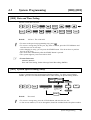
This manual was printed
with soy based ink.
KX-TA308
KX-TA616
Please read this manual before connecting
the Advanced Hybrid System.
System Highlights
System Capacity
Basic System
Expansion
<KX-TA308>
Extensions
8
Outside (CO) lines
3
Maximum extensions
24
Maximum outside (CO) lines 6
<KX-TA616>
16
6
24
6
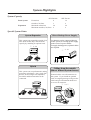
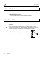
Special System Points
System Expansion
Direct Backup Power Supply
This system can expand the outside (CO)
lines (KX-TA308 only) and extension
capacity by installing an optional card.
☞ 2– 24
Car batteries can be connected directly
to this system as a backup power supply
in the event of a power failure.
To supply backup power, optional cables
are required.
☞ 2– 23
Hybrid
This system can accept Panasonic analog
proprietary telephones. Also, single line
devices such as single line telephones,
facsimiles and data terminals can be
connected.
2
Calling from the outside
(Direct Inward System Access)
External callers can call extensions in
the system. If you install an optional
card, an outgoing message will greet the
caller and give information about how
to access an extension.
☞ 3– 17
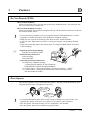
Precautions
• Keep the unit away from heating appliances and electrical noise generating devices such as
fluorescent lamps, motors and televisions. These noise sources can interfere with the
performance of the Advanced Hybrid System.
• This unit should be kept free of dust, moisture, high temperature (more than 40 ˚C {104 ˚F})
and vibration, and should not be exposed to direct sunlight.
• Never attempt to insert wires, pins, etc. into the vents or other holes of this unit.
• If there is any trouble, disconnect the unit from the telephone line. Plug the telephone directly
into the telephone line. If the telephone operates properly, do not reconnect the unit to the line
until the trouble has been repaired. If the telephone does not operate properly, chances are that
the trouble is in the telephone system, and not in the unit.
• Do not use benzine, thinner, or the like, or any abrasive powder to clean the cabinet. Wipe it
with a soft cloth.
WARNING
THIS UNIT MAY ONLY BE INSTALLED AND SERVED BY QUALIFIED
SERVICE PERSONNEL.
WHEN A FAILURE OCCURS WHICH RESULTS IN THE INTERNAL PARTS
BECOMING ACCESSIBLE, DISCONNECT THE POWER SUPPLY CORD
IMMEDIATELY AND RETURN THIS UNIT TO YOUR DEALER.
DISCONNECT THE TELECOM CONNECTION BEFORE DISCONNECTING THE
POWER CONNECTION PRIOR TO RELOCATING THE EQUIPMENT, AND
RECONNECT THE POWER FIRST.
THIS UNIT IS EQUIPPED WITH AN EARTHING CONTACT PLUG. FOR SAFETY
REASONS THIS PLUG MUST ONLY BE CONNECTED TO AN EARTHING
CONTACT SOCKET WHICH HAS BEEN INSTALLED ACCORDING TO
REGULATIONS.
THE POWER SUPPLY CORD IS USED AS THE MAIN DISCONNECT DEVICE,
ENSURE THAT THE SOCKET-OUTLET IS LOCATED/INSTALLED NEAR THE
EQUIPMENT AND IS EASILY ACCESSIBLE.
TO PREVENT FIRE OR SHOCK HAZARD, DO NOT EXPOSE THIS PRODUCT
TO RAIN OR MOISTURE.
3
Precautions
For your future reference
SERIAL NO.
DATE OF PURCHASE
(found on the bottom of the unit)
NAME OF DEALER
DEALER’S ADDRESS
Note • This Installation Manual does not show complete model number that indicate the
country where your models should be used. The model number of your unit is found
on the label affixed to the unit.
MODEL NO. – – – – – – – –
(label)
4
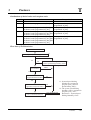
Introduction
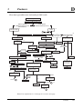
Structure of the Manual
This manual consists of the following sections:
Section 1. Basic System Construction
Provides general information on the system including connection diagrams.
Section 2. Installation
Contains the system installation and wiring instructions, as well as how to install the
optional cards.
Section 3. Features
Describes the optional and programmable features in alphabetical order. It also provides
information about the conditions, required System Programming, connection references,
related features and operating instructions references for every feature.
Section 4. System Programming
Describes the steps required to assign features to extensions or to the system.
Section 5. Appendix
Provides specifications and the default values of the System Programming.
Section 6. Troubleshooting
Provides information for system and telephone troubleshooting.
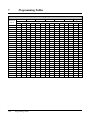
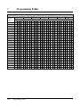
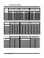
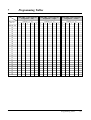
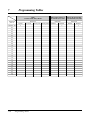
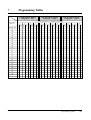
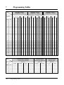
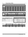
Section 7. Programming Tables
Provides programming tables for user-programmed data.
Description of the Symbols Mainly Used in this manual
!
☞
Additional information and conditions.
The feature or program references.
5
Contents
Section 1
Basic System Construction
Section 2
Installation
2.1
2.2
2.3
2.4
2.5
2.6
2.7
2.8
2.9
2.10
2.11
2.12
2.13
2.14
2.15
2.16
2.17
2.18
2.19
2.20
2.21
2.22
2.23
2.24
Section 3
2-2
2-4
2-4
2-5
2-6
2-6
2-7
2-9
2-10
2-11
2-12
2-13
2-14
2-17
2-17
2-19
2-23
2-24
2-29
2-29
2-30
2-31
2-33
2-34
Features
A
B
C
6
Before Installation .................................................................................
Unpacking ..............................................................................................
Names and Locations ............................................................................
Wall Mounting .......................................................................................
Frame Ground Connection ..................................................................
Opening the Top Front Cover ..............................................................
Outside (CO) Line Connection ............................................................
Extension Connection ...........................................................................
External Pager (Paging Equipment) Connection...............................
External Music Connection..................................................................
Paralleled Telephone Connection.........................................................
Polarity Sensitive Telephone Connection ............................................
Printer and PC Connection..................................................................
Location of Optional Cards..................................................................
OGM/FAX Detection Card Installation ..............................................
Doorphone and Door Opener Connection..........................................
Backup Batteries Connection...............................................................
Installing a 3-CO Line & 8 Ext Expansion Card (KX-TA30877)
and 8 SLT Extn. Expansion Card (KX-TA30874) .............................
Auxiliary Connection for Power Failure Transfer .............................
Securing the Cords................................................................................
Closing the Front Cover .......................................................................
Starting the System for the First Time ...............................................
System Restart .......................................................................................
System Data Clear.................................................................................
Absent Message Capability ................................................................
Account Code Entry ...........................................................................
Alternate Calling – Ring/Voice ..........................................................
Automatic Callback Busy (Camp-On) ...............................................
Automatic Outside (CO) Line Access Number..................................
Automatic Route Selection (ARS) .....................................................
Busy Station Signaling (BSS) ............................................................
Call Forwarding ..................................................................................
Calling Party Control (CPC) Signal Detection ..................................
Call Park .............................................................................................
Call Pickup .........................................................................................
Call Splitting.......................................................................................
Call Transfer – to Extension...............................................................
Call Transfer – to Outside (CO) Line ................................................
3-2
3-2
3-3
3-3
3-4
3-4
3-8
3-9
3-10
3-10
3-11
3-11
3-12
3-12
Contents
C
D
E
F
H
I
L
M
O
Call Waiting ........................................................................................
Conference (3-party) ..........................................................................
Conference (5-party) ..........................................................................
Data Line Security..............................................................................
Date and Time Setting ........................................................................
Direct In Line (DIL)...........................................................................
Direct Inward System Access (DISA)................................................
Display Contrast Adjustment
(KX-T7330/KX-T7030/KX-T7130/KX-T7033 only)......................
Distinctive Dial Tones ........................................................................
Do Not Disturb (DND).......................................................................
Door Opener .......................................................................................
Doorphone Call ..................................................................................
DSS Console.......................................................................................
Emergency Call ..................................................................................
Executive Busy Override....................................................................
Extension Button Confirmation
(KX-T7330/KX-T7030/KX-T7130/KX-T7033 only)......................
Extension Group.................................................................................
Extension Password / System Password ............................................
External Feature Access .....................................................................
Flash....................................................................................................
Flexible Buttons..................................................................................
Handset/Headset Selection
(KX-T7330/KX-T7030/KX-T7130/KX-T7033 only)......................
Handsfree Answerback.......................................................................
Handsfree Operation...........................................................................
Hold .................................................................................................
Hookswitch Flash ...............................................................................
Host PBX Access................................................................................
Intercept Routing ................................................................................
Intercom Calling.................................................................................
Language Selection ............................................................................
Limited Call Duration ........................................................................
Line Access Buttons ...........................................................................
Log-In/Log-Out ..................................................................................
Message Waiting.................................................................................
Microphone Mute ...............................................................................
Music on Hold / Background Music (BGM) .....................................
One-Touch Dialing .............................................................................
Operator / Manager Extension ...........................................................
Operator Call ......................................................................................
Outgoing Message (OGM).................................................................
Outside Calling...................................................................................
Outside (CO) Line Ringing Selection ................................................
3-13
3-14
3-15
3-15
3-16
3-16
3-17
3-24
3-24
3-25
3-25
3-26
3-27
3-27
3-28
3-28
3-29
3-29
3-30
3-30
3-31
3-32
3-32
3-32
3-33
3-34
3-34
3-35
3-35
3-36
3-36
3-37
3-38
3-38
3-39
3-39
3-39
3-40
3-40
3-41
3-44
3-45
7
Contents
P
R
S
T
U
V
W
Section 4
4.1
4.2
8
Paging .................................................................................................
Paralleled Telephone Connection .......................................................
Personal Speed Dialing ......................................................................
Pickup Dialing ....................................................................................
Polarity Reverse Detection .................................................................
Power Failure Transfer .......................................................................
Preferred Line Assignment — Incoming ...........................................
Preferred Line Assignment — Outgoing............................................
Proprietary Telephone Setting Data Default Set ................................
Pulse to Tone Conversion ...................................................................
Receiving Calls...................................................................................
Redial .................................................................................................
Ringing Pattern Selection ...................................................................
Room Monitor ....................................................................................
Secret Dialing .....................................................................................
Self-Extension Number Confirmation
(KX-T7330/KX-T7030/KX-T7130/KX-T7033 only)......................
Station Feature Clear ..........................................................................
Station Hunting...................................................................................
Station Lock........................................................................................
Station Message Detail Recording (SMDR) ......................................
System Data Default Set ....................................................................
System Speed Dialing ........................................................................
Timed Reminder .................................................................................
Time (Day/Night/Lunch) Service.......................................................
Toll Restriction ...................................................................................
Toll Restriction for System Speed Dialing.........................................
Toll Restriction Override by Account Codes .....................................
Toll Restriction – Station Lock Boundary Class................................
Uniform Call Distribution (UCD) ......................................................
Voice Mail Integration for KX-TVP75/KX-TVP100.........................
Volume Control ..................................................................................
Walking COS......................................................................................
3-45
3-46
3-46
3-47
3-47
3-48
3-48
3-49
3-49
3-50
3-50
3-50
3-51
3-52
3-52
3-53
3-53
3-54
3-55
3-56
3-57
3-58
3-58
3-59
3-60
3-62
3-63
3-64
3-64
3-68
3-71
3-71
System Programming
Before System Programming ...............................................................
System Programming............................................................................
[000] Date and Time Setting.............................................................
[001] System Speed Dialing Entry ...................................................
[002] System Password.....................................................................
[003] DSS Console Port Assignment................................................
[004] Paired Telephone Assignment for DSS Console ....................
[005] One-Touch Transfer Using a DSS Button .............................
[006] Time (Day/Night/Lunch) Service Changing Mode ...............
4-2
4-5
4-5
4-5
4-6
4-7
4-7
4-8
4-8
Contents
[007]
[008]
[009]
[010]
[011]
[012]
[100]
[101]
[102]
[103]
[104]
[105]
[106]
[107]
[108]
[109]
[110]
[111]
[112]
[113]
[114]
[115]
[116]
[117]
[118]
[119]
[120]
[121]
[122]
[123]
[124]
[125]
[126]
[127]
[200]
[201]
[202]
[203]
[204]
[205]
[206]
[207]
[208]
[210]
Time (Day/Night/Lunch) Service Start Time ........................
Operator Assignment ..............................................................
Extension Number Assignment ..............................................
LCD Time Display Selection .................................................
System Speed Dialing Name Setting .....................................
Second Feature Numbering Plan ...........................................
Hunting Group Set .................................................................
Hunting Type ..........................................................................
Voice Mail Port for KX-TVP75/KX-TVP100 .......................
DTMF Integration for KX-TVP75/KX-TVP100 ...................
Hold Mode Selection .............................................................
Conference Tone ....................................................................
External Paging Access Tone .................................................
DTMF Receiver Check ..........................................................
Flash Mode for a Station Locked Extension .........................
CO Indicator Assignment .......................................................
Flash Key Mode .....................................................................
Hold Music Selection .............................................................
DSS Console Indication Mode ..............................................
Automatic Redial Repeat .......................................................
Automatic Redial Interval Time .............................................
Extension Ringing Pattern Selection .....................................
Conference Pattern Selection .................................................
Call Pickup Tone ....................................................................
Pulse Restriction ....................................................................
Redialing after Pulse to Tone Conversion ..............................
Bell Frequency .......................................................................
Automatic Outside (CO) Line Access Number Selection .....
Automatic Rotation for Outside (CO) Line Access ...............
Break Ratio ...........................................................................
SLT Ringing Mode Selection .................................................
Toll Restriction Check for
and # .......................................
DSS Off-Hook Mode ..............................................................
Pickup Group Set ....................................................................
Hold Recall Time ...................................................................
Transfer Recall Time ..............................................................
Call Forwarding Start Time ...................................................
Pickup Dial Delay Time .........................................................
Call Duration Count Start Time .............................................
Outside-to-Outside (CO-to-CO) Line Duration Time Limit .....
Dialing Start Time ..................................................................
Hookswitch Flash Timing Range Selection ...........................
Interdigit Time ........................................................................
DTMF Time ...........................................................................
4-9
4-10
4-10
4-11
4-12
4-13
4-14
4-14
4-15
4-15
4-17
4-17
4-18
4-18
4-18
4-19
4-19
4-20
4-20
4-21
4-21
4-22
4-22
4-23
4-23
4-23
4-24
4-24
4-24
4-25
4-25
4-25
4-26
4-26
4-27
4-27
4-27
4-28
4-28
4-29
4-29
4-30
4-30
4-31
9
Contents
[211] No Dial Disconnection ...........................................................
[212] Outside (CO) Line Duration Time Limit ...............................
[213] Bell Off Detection ..................................................................
[300] Carrier Excepted Code Assignment .......................................
[301] Toll Restriction — System Speed Dialing Boundary Class ..
[302]–[305] Toll Restriction — Classes 2 through 5 Denied Codes ..
[306] Toll Restriction — Exception Codes .....................................
[309] Emergency Dial Number Set .................................................
[310] Account Codes .......................................................................
[311] Automatic Pause Insertion Codes ..........................................
[312] Toll Restriction — Station Lock Boundary Class .................
[350] ARS Selection .........................................................................
[351]-[354] Routes 1 through 4 Selection Codes (Leading Digits)...
[355]-[358] Routes 1 through 4 Exception Codes .............................
[359] 1st Carrier Selection Code ......................................................
[360] ARS Modification — Removed Digits...................................
[361] ARS Modification — Added Number ....................................
[362] ARS Dial Tone Pattern Selection............................................
[363] ARS Interdigit Time................................................................
[364] ARS Outside (CO) Line Group ..............................................
[400] Outside (CO) Line Connection Assignment ..........................
[401] Dial Mode ..............................................................................
[402] Pulse Speed Selection ............................................................
[403] Host PBX Access Codes ........................................................
[404] Outside (CO) Line Group Assignment ..................................
[405]–[407] Flexible Outward Dialing Assignment
— Day/Night/Lunch ......................................................................
[408]–[410] Flexible Ringing Assignment — Day/Night/Lunch ....
[411]–[413] Delayed Ringing Assignment — Day/Night/Lunch ....
[414]–[416] Outside (CO) Line Mode — Day/Night/Lunch ...........
[417] Pause Time .............................................................................
[418] Flash Time ..............................................................................
[419] Automatic Designated Outside (CO) Line Access ................
[420] Calling Party Control (CPC) Signal ......................................
[421] CPC Detection for Outgoing Calls ........................................
[422] Disconnect Time ....................................................................
[423] Outside (CO) Line Ringing Pattern Selection .......................
[424] Reverse (Polarity) Circuit Assignment ..................................
[500] DISA Incoming Dialing Mode Selection ..............................
[501] DISA Built-in Auto Attendant ...............................................
[502] OGM Mode Selection ............................................................
[503] FAX Connection ....................................................................
[504] DISA Delayed Answer Time .................................................
10
4-31
4-32
4-32
4-33
4-33
4-34
4-35
4-35
4-36
4-36
4-37
4-38
4-38
4-39
4-39
4-40
4-40
4-41
4-41
4-42
4-43
4-43
4-44
4-44
4-45
4-46
4-47
4-48
4-49
4-50
4-51
4-51
4-52
4-53
4-53
4-54
4-55
4-56
4-57
4-58
4-59
4-59
Contents
[505] DISA Waiting Time after OGM .............................................
[506] DISA Busy Mode ...................................................................
[507] DISA Intercept Mode .............................................................
[508] DISA Ringing Time before Intercept ....................................
[509] DISA Ringing Time after Intercept .......................................
[510] DISA No Dial Mode ..............................................................
[511] DISA Security Type ................................................................
[512] DISA Security Codes .............................................................
[513] Cyclic Tone Detection ............................................................
[514] Fax Tone Detection ................................................................
[515] Intercept Time for Internal DISA ..........................................
[516] DISA Incoming Assignment ..................................................
[517] DISA AA Wait Time ..............................................................
[518] DISA Tone Selection after the Security Code ........................
[519] DISA OGM Mute Time .........................................................
[520] UCD Group ............................................................................
[521] UCD Busy Waiting Time .......................................................
[522] UCD OGM Message Interval Time .......................................
[523] UCD Busy Mode ....................................................................
[524] UCD Intercept Mode ..............................................................
[525] UCD Ringing Time before Intercept .....................................
[526] UCD Ringing Time after Intercept ........................................
[600] Extension Group Assignment ................................................
[601]–[603] TRS – Class of Service Assignment
— Day/Night/Lunch ......................................................................
[604] Extension Name Setting .........................................................
[605] Account Code Entry Mode ....................................................
[606] Call Transfer to an Outside (CO) Line ..................................
[607] Call Forwarding to an Outside (CO) Line .............................
[608] Executive Busy Override .......................................................
[609] Do Not Disturb Override .......................................................
[610] Paralleled Telephone Connection ...........................................
[611] TAM (Telephone Answering Machine) Extension ................
[612] Room Monitor Assignment ....................................................
[613] Outside (CO) Line Duration Time Limit Selection ...............
[614] Internal Pulse Detection .........................................................
[615] LCD Language Assignment ...................................................
[700]–[702] Doorphone Ringing Assignment — Day/Night/Lunch ..
[703]–[705] Door Opener Assignment — Day/Night/Lunch ..........
[706] Doorphone Ringing / Tone Pattern Selection ........................
[707] Doorphone Access Tone Selection .........................................
[708] Doorphone Ringing Time ......................................................
[709] Door Opener Time .................................................................
4-59
4-60
4-60
4-61
4-61
4-62
4-62
4-63
4-63
4-64
4-64
4-65
4-65
4-66
4-66
4-67
4-67
4-67
4-68
4-68
4-69
4-69
4-70
4-70
4-71
4-72
4-73
4-73
4-74
4-74
4-75
4-75
4-76
4-76
4-77
4-78
4-79
4-80
4-81
4-81
4-82
4-82
11
Contents
[800]
[801]
[802]
[803]
[804]
[805]
[806]
[998]
[999]
Section 5
5.1
5.2
Section 6
6.1
6.2
6.3
Section 7
Template
12
SMDR RS-232C Communication Parameters .......................
SMDR Parameter ...................................................................
Incoming/Outgoing Call Selection for Printing .....................
Secret Speed Dialing / One-Touch Dialing Printing .............
System Data Dump ................................................................
SMDR Account Code Selection ............................................
SMDR Language Assignment ................................................
ROM Version ..........................................................................
System Data Clear ..................................................................
4-83
4-84
4-84
4-85
4-85
4-86
4-87
4-87
4-88
Appendix
Default Values ........................................................................................
Specifications .........................................................................................
5-2
5-7
Troubleshooting
While Installing ....................................................................................
While Connecting ..................................................................................
While Operating ....................................................................................
Programming Tables
6-2
6-3
6-4
Section 1
Basic System Construction
1
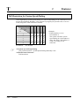
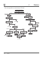
Basic System Construction
The KX-TA308 has a basic capacity of 8 extensions and 3 outside (CO) lines, and the
KX-TA616 has 16 extensions and 6 outside (CO) lines. It is capable of supporting
Panasonic analog proprietary telephones, and single line devices such as single line
telephones, facsimiles and data terminals.
To expand its capabilities, the system can be equipped with optional components or
customer-supplied peripherals such as an external speaker, external music source (e.g. a
radio) and door opener.
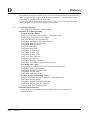
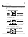
System Connection Diagram
■ KX-TA308
6 Outside (CO) Lines
to outside lines 1 – 3 (initial)
to outside lines 4 – 6 (additional)
(Lightning Protectors)
car batteries
External Music Source
Amplifier
Printer
or
Speaker
Computer
24 Extensions
Extension jacks 01 – 08 (initial)
Extension jacks 09 – 24 (additional)
(two pair)
(one pair)
(two pair)
Single Line Telephone
(one pair)
KX-T7020
(two pair)
KX-T7130
(two pair)
Data Terminal
Door Openers
(one pair)
KX-T7030/KX-T7033
KX-T7040
(two pair)
(two pair)
Panasonic
Cordless Phone
(one pair)
KX-T7050
(two pair)
KX-T7055
(two pair)
Panasonic
Telephone Answering Machine
with Facsimile
Panasonic
(one pair)
KX-T7320
KX-T7330
(two pair)
(two pair)
Panasonic
Doorphones
KX-T30865
1-2
Voice Processing System
Basic System Construction
KX-T7340
KX-T7350
: needs optional card.
1
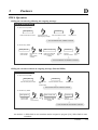
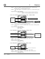
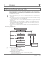
Basic System Construction
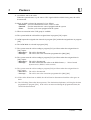
■ KX-TA616
6 Outside (CO) Lines
to outside lines 1 – 6
(Lightning Protectors)
car batteries
External Music Source
Amplifier
Printer
or
Speaker
Computer
24 Extensions
Extension jacks 01 – 16 (initial)
Extension jacks 17 – 24 (additional)
(two pair)
(one pair)
(two pair)
Single Line Telephone
(one pair)
KX-T7020
(two pair)
KX-T7130
(two pair)
Data Terminal
Door Openers
(one pair)
KX-T7040
(two pair)
KX-T7030/KX-T7033
(two pair)
Panasonic
Cordless Phone
(one pair)
KX-T7050
(two pair)
KX-T7055
(two pair)
Panasonic
Telephone Answering Machine
with Facsimile
Panasonic
(one pair)
KX-T7320
KX-T7330
(two pair)
(two pair)
Panasonic
Doorphones
KX-T30865
!
Voice Processing System
KX-T7340
KX-T7350
• We recommend connecting a display proprietary telephone at extension jack 01.
• Parallel connection of telephone is possible. (☞ 2.11, Paralleled Telephone Connection)
• A proprietary telephone cannot be connected to extension jacks 17 through 24. Only a
single line telephone (SLT) can be connected.
: needs optional card.
Basic System Construction
1-3
1-4
Basic System Construction
Section 2
Installation
2.1
Before Installation
Please read the following notes concerning installation and connection before installing the
system and terminal equipment.
Safety Installation Instructions
When installing telephone wiring, basic safety precautions should always be followed to
reduce the risk of fire, electric shock and injury to persons, including the following:
1. Never install telephone wiring during a lightning storm.
2. Never install telephone jacks in wet locations unless the jack is specifically designed for
wet locations.
3. Never touch uninsulated telephone wires or terminals unless the telephone line has been
disconnected at the network interface.
4. Use caution when installing or modifying telephone lines.
Installation Precautions
This system is designed for wall mounting only. Avoid installing in the following places.
(Doing so may result in malfunction, noise, or discoloration.)
1. In direct sunlight and hot, cold, or humid places. (Temperature range: 0 °C – 40 °C
{32 °F – 104 °F})
2. Sulfuric gases produced in areas where there are thermal springs, etc. may damage the
equipment or contacts.
3. Places in which shocks or vibrations are frequent or strong.
4. Dusty places, or places where water or oil may come into contact with the system.
5. Near high-frequency generating devices such as sewing machines or electric welders.
6. On or near computers, telexes, or other office equipment, as well as microwave ovens or
air conditioners. (It is preferable not to install the system in the same room with the above
equipment.)
7. Install at least 1.8 m {6 feet} away from radios and televisions. (Both the system and
Panasonic proprietary telephones)
8. Do not obstruct area around the system (for reasons of maintenance and inspection — be
especially careful to allow space for cooling above and at the sides of the system).
Wiring Precautions
Be sure to follow these instructions when wiring the unit:
1. Do not wire the telephone cable in parallel with an AC power source, computer, telex, etc.
If the cables are run near those wires, shield the cables with metal tubing or use shielded
cables and ground the shields.
2. If cables are run on the floor, use protectors to prevent the wires from being stepped on.
Avoid wiring under carpets.
3. Avoid using the same power supply outlet for computers, telexes, and other office
equipment. Otherwise, the system operation may be interrupted by the induction noise
from such equipment.
2-2
Installation
2.1
Before Installation
4. Please use one pair telephone wire for extension connection of (telephone) equipment
such as single line telephones, data terminals, answering machines, computers, voice
processing systems, etc., except Panasonic proprietary telephones (e.g. KX-T7330).
5. Unplug the system during wiring. After all of the wiring is completed, plug in the
system.
6. Mis-wiring may cause the system to operate improperly. Refer to Section 6.1 “While
Installing” and Section 6.2 “While Connecting”.
7. If an extension does not operate properly, disconnect the telephone from the extension
line and then connect again, or turn off the Power Switch of the system and then on
again.
8. The system is equipped with a 3-wire grounding type plug. This is a safety feature. If
you are unable to insert the plug into the outlet, contact your electrician to replace your
obsolete outlet. Do not defeat the purpose of the grounding-type plug.
9. Outside (CO) lines should be installed with lightning protectors. For details, refer to
Section 2.7 “Outside (CO) Line Connection”, Installing Lightning Protectors.
Warning:
Side View
Static sensitive devices
are used. To protect
printed circuit boards
from static electricity, do
not touch connectors
indicated to the left. To
discharge body static,
touch ground or wear a
grounding strap.
Warning: Static sensitive connectors
* The illustration on this page is a KX-TA308.
Installation
2-3
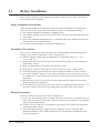
2.2
Unpacking
Unpack the box and check the items below.
2.3
Main Unit
1
Music Source Connector
1
AC Cord
1
Plug Adaptor
1
Screws (Wall Mounting)
3
Strap
1
Washers (Wall Mounting)
3
Rivet
1
Pager Connector
1
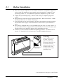
Names and Locations
■ KX-TA308
External Music Jack
Paging Jack
Extension Modular Jacks
Strap Hole
Outside (CO) Line Modular Jacks
Serial Interface
(RS-232C)
Power Switch
Side View
Battery Interface
Protective Earth Terminal
AC Inlet
Power Indicator
■ KX-TA616
External Music Jack
Paging Jack
Extension Modular Jacks
Strap Hole
Outside (CO) Line Modular Jacks
Serial Interface
(RS-232C)
Power Switch
Side View
Battery Interface
Protective Earth Terminal
AC Inlet
2-4
Installation
Power Indicator
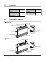
2.4
Wall Mounting
This set is designed for wall mounting only. The wall where the main unit is to be mounted
must be able to support the weight of the main unit. If screws other than the ones supplied
are used, use screws with the same diameter as the ones enclosed.
Mounting on a Wooden Wall
Mounting on a Concrete or Mortar
Wall
1. Place the template (on the last page) on the wall
to mark the screw positions.
1. Place the template (on the last page) on the wall
to mark the screw positions.
2. Drill holes and drive the anchor plugs (usersupplied) with a hammer, flush to the wall.
To the wall surface
Concrete Wall
Anchor Plug
Template
6.4 mm
{1/4 inch}
29 mm
{1 1/8 inch}
2. Install the screws (included) into the wall.
Wooden
Wall
3. Install the screws (included) into the anchor
plugs.
Drive the screw
to this position
Drive the screw
to this position
3. Hook the main unit on the screw heads.
4. Hook the main unit on the screw heads.
Installation
2-5
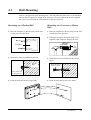
2.5
Frame Ground Connection
IMPORTANT!!!
Connect the frame of the main unit to
the ground.
1. Loosen the screw.
2. Insert the grounding wire (usersupplied).
To the ground
Screw
3. Tighten the screw.
4. Connect the grounding wire to the
ground.
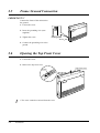
2.6
Opening the Top Front Cover
1. Loosen the screw.
2. Remove the top front cover.
Top front cover
Screw
!
2-6
• The screw cannot be removed from the cover.
Installation
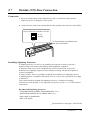
2.7
Outside (CO) Line Connection
Connection
1. Insert the modular plugs of the telephone line cords (2-conductor wiring) into the
modular jacks (CO 1 through 3) on the system.
2. Connect the line cords to the terminal board or the modular jacks from the Central Office.
View of TEL Jack (Outside (CO) Line)
T: Tip
R: Ring
T R
To Terminal Board or Modular Jacks
from the Central Office
Installing Lightning Protectors
A lightning protector is a device to be installed on an outside (CO) line to prevent a
dangerous surge from entering the building and damaging the equipment.
A dangerous surge can occur if a telephone line comes in contact with a power line.
Problems due to lightning surges have been steadily increasing with the development of
electronic equipment.
In many countries, there are regulations requiring the installation of a lightning protector.
A lightning strike to a telephone cable which is 10 m {33 feet} above ground can be as high
as 200 000 V.
This system should be installed with lightning protectors. In addition, grounding
(connection to earth ground) is very important to protect the system (☞ 2.5, Frame Ground
Connection).
Recommended lightning protectors
• TELESPIKE BLOK MODEL TSB (TRIPPE MFG. CO.)
• SPIKE BLOK MODEL SK6-0 (TRIPPE MFG. CO.)
• Super MAX™ (PANAMAX)
• MP1 (ITW LINK)
* The illustration on this page is a KX-TA308.
Installation
2-7
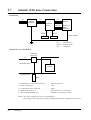
2.7
Outside (CO) Line Connection
Installation
CO
CO
Lightning
Protectors
CO
System
Terminal
Board
EXTN.
EXTN.
TEL
Protective
Earth
Terminal
EXTN.
TEL
Frame Ground
CO:
Outside line
EXTN.: Extension line
TEL:
Telephone
Ground
Installation of an Earth Rod
Lightning
Protectors
CO
Grounding Wire
System
(Underground)
Rod
1)
2)
3)
4)
5)
Installation location of the earth rod . . . . . . Near the protector
Check obstructions . . . . . . . . . . . . . . . . . . . None
Composition of the earth rod . . . . . . . . . . . Metal
Depth of the earth rod . . . . . . . . . . . . . . . . More than 50 cm {20 inches}
Size of the grounding wire . . . . . . . . . . . . . Thickness more than 16 AWG
Note • The above example is only a recommendation.
• The length of the earth rod and required depth depend on the composition of the soil.
2-8
Installation
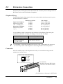
2.8
Extension Connection
Extension jacks 01 through 08 for the KX-TA308 and extension jacks 01 through 16 for the
KX-TA616 can be used for all kinds of telephones.
Telephone Wiring
The maximum length of the extension line cord (twisted cable) which connects the system
and the extension is as follows.
Diameter of the line
Max. length
Single Line Telephone
22 AWG
1798 m {5900 feet}
(Station Loop Limit:
24 AWG
1128 m {3700 feet}
600 Ω including set)
26 AWG
698 m {2290 feet}
Proprietary Telephone
22 AWG
360 m {1180 feet}
(Station Loop Limit:
24 AWG
229 m {750 feet}
40 Ω)
26 AWG
140 m {460 feet}
2 or 4-conductor wiring is required for each extension as listed below. There are 4 pins
possible for connection: “T” (Tip), “R” (Ring), “L” (Low) and “H” (High).
Telephone
!
Wiring
Single line telephones
1 pair wire (T, R)
Proprietary telephone
(e.g., KX-T7330)
2 pair wire (L, H, T, R)
• If a telephone or answering machine with an A-A1 relay is connected to the system, set
the A-A1 relay switch on the telephone or answering machine to the OFF position.
Connection
Insert the modular plugs of the telephone line cords (2 or 4-conductor wiring) into the
modular jacks on the system.
View of TEL Jack (Extension)
H: High
T: Tip
R: Ring
L: Low
H TR L
To extensions
(JACK 01–08 for the KX-TA308,
JACK 01–16 for the KX-TA616)
* The illustration on this page is a KX-TA308.
Installation
2-9
2.9
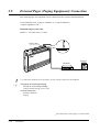
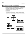
External Pager (Paging Equipment) Connection
One external pager (user-supplied) can be connected to the system as illustrated below.
Use an EIAJ RC-6701 A plug (2-conductor, ø 3.5 mm in diameter).
• Output impedance: 600 Ω
Maximum length of the cable
AWG 18 – 22: Under 10 m {33 feet}
Paging Jack
ER
POW
PAGING
Speaker
Amplifier
Paging Equipment
!
☞
• To adjust the sound level of the pager, use the volume control on the amplifier.
• Required System Programming
Section 4.2, System Programming
[106] External Paging Access Tone
• Feature Reference
Section 3, Features
Paging
* The illustration on this page is a KX-TA308.
2-10
Installation
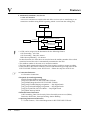
2.10
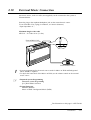
External Music Connection
One music source, such as a radio (user-supplied), can be connected to the system as
illustrated below.
Insert the plug to the earphone/headphone jack on the external music source.
Use an EIAJ RC-6701 A plug (2-conductor, ø 3.5mm in diameter).
• Input impedance: 8 Ω
Maximum length of the cable
AWG 18 – 22: Under 10 m {33 feet}
External Music Jack
EXT.
MUSIC
ER
POW
External Music source
!
☞
• System programming for the music sources used for Music on Hold and Background
Music (BGM) is required.
• To adjust the sound level of the Music on Hold, use the volume control on the external
music source.
• Required System Programming
Section 4.2, System Programming
[111] Hold Music Selection
• Feature Reference
Section 3, Features
Music on Hold / Background Music (BGM)
* The illustration on this page is a KX-TA308.
Installation
2-11
2.11
Paralleled Telephone Connection
Any single line telephone can be connected in parallel with a proprietary telephone as
follows.
Using a Modular T-Adaptor
Modular T-Adaptor
(Panasonic KX-J66 or USOC RJA2X)
2-conductor wiring cord
Connect pins “T” and “R”.
4-conductor wiring cord
For a proprietary telephone:
Connect pins “T”, “R”, “H” and “L”.
Proprietary Telephone
☞
• Required System Programming
Section 4.2, System Programming
[610] Paralleled Telephone Connection
• Feature Reference
Section 3, Features
Paralleled Telephone Connection
2-12
Installation
Single Line Telephone
2.12
Polarity Sensitive Telephone Connection
If your telephone is polarity sensitive, follow the procedure below:
1. Complete all the required extension wiring.
2. Confirm that dialing can be done from all the
extensions using a touch-tone telephone.
If dialing fails, the polarity between the extension
and the system must be reversed.
3. Reverse as shown.
Extension
Outside (CO) Line
1
2
3
4
5
6
7
8
9
4. Unplug the system.
5. Connect all outside lines.
0
Reverse here
6. Confirm that dialing can be done on the following
extension using a touch-tone telephone.
Extension (T, R) of jack 01: Outside (CO) line 1
If dialing fails, the polarity between the system and
the outside line must be reversed.
7. Reverse as shown.
Extension
Outside (CO) Line
2
3
4
5
6
7
8
9
1
8. Every time an extension telephone is replaced,
repeat the procedure above.
0
Reverse here
Installation
2-13
2.13
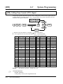
Printer and PC Connection
A user-supplied printer or personal computer (PC) can be connected to the system. These
are used to print out or refer to the SMDR call records and system programming data.
Connect the printer cable or the PC cable to the Serial Interface (RS-232C) connector. The
cable must be shielded and the maximum length is 2 m {6.5 feet}.
Serial Interface
(RS-232C) (D-SUB, 9-pin)
Printer
or
Computer
Arrange the cables so that the printer will be connected to the system as shown in the
appropriate chart on the following page.
The pin configuration of the Serial Interface (RS-232C) Connector is as follows.
Pin
Signal Name
EIA
No.
2-14
Circuit Type
CCITT
2
RXD
Received Data
BB
104
3
4
TXD
DTR
Transmitted Data
Data Terminal Ready
BA
CD
103
108.2
5
6
SG
DSR
Signal Ground
Data Set Ready
AB
CC
102
107
7
8
RTS
CTS
Request To Send
Clear To Send
CA
CB
105
106
Installation
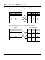
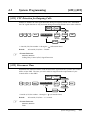
2.13
Printer and PC Connection
Connection Chart for a Printer / Personal Computer with the System
If you connect a printer or a PC with a 9-pin cable, follow the chart below.
System
9-pin Cable Printer/PC
Circuit type
(EIA)
Signal
name
Pin
no.
Pin
no.
Signal
name
Circuit type
(EIA)
BB
RXD
2
2
RXD
BB
BA
TXD
3
3
TXD
BA
CD
DTR
4
4
DTR
CD
AB
SG
5
5
SG
AB
CC
DSR
6
6
DSR
CC
CA
RTS
7
7
RTS
CA
CB
CTS
8
8
CTS
CB
If you connect a printer or a PC with a 25-pin cable, follow the chart below.
System
25-pin Cable Printer/PC
Circuit type
(EIA)
Signal
name
Pin
no.
Pin
no.
Signal
name
Circuit type
(EIA)
BB
RXD
2
1
FG
AA
BA
TXD
3
3
RXD
BB
CD
DTR
4
2
TXD
BA
AB
SG
5
20
DTR
CD
CC
DSR
6
7
SG
AB
CA
RTS
7
5
CTS
CB
CB
CTS
8
6
DSR
CC
8
DCD
CF
Installation
2-15
2.13
Printer and PC Connection
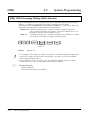
Serial Interface (RS-232C) Signals
Frame Ground: FG
Connects the unit frame and the earth ground conductor of the AC power cord.
Transmitted Data: SD (TXD) . . . . . . . . . . . . . . . . . . . . . . (output)
Conveys signals from the unit to the printer. A “Mark” condition is held unless data or
BREAK signals are being transmitted.
Received Data: RD (RXD) . . . . . . . . . . . . . . . . . . . . . . . . (input)
Conveys signals from the printer.
Request to Send: RS (RTS) . . . . . . . . . . . . . . . . . . . . . . . (output)
This lead remains ON whenever DR (DSR) is ON.
Clear To Send: CS (CTS) . . . . . . . . . . . . . . . . . . . . . . . . . (input)
When the CS (CTS) circuit is ON, it indicates that the printer is ready to receive data from
the unit. The unit does not attempt to transfer data or receive data when the CS (CTS) circuit
is OFF.
Data Set Ready: DR (DSR) . . . . . . . . . . . . . . . . . . . . . . . (input)
When the DR (DSR) circuit is ON, it indicates the printer is ready. The DR (DSR) circuit
being ON does not indicate that communication has been established with the printer.
Signal Ground: SG
Connects the DC ground of the unit for all interface signals.
Data Terminal Ready: ER (DTR) . . . . . . . . . . . . . . . . . . (output)
This signal line is turned ON by the unit to indicate that it is ON
LINE. The ER (DTR) circuit being ON does not indicate that communication has been
established with the printer. It is switched OFF when the unit is OFF LINE.
Data Carrier Detect: CD (DCD) . . . . . . . . . . . . . . . . . . . (input)
When ON, it indicates the data terminal (DTE) that the carrier signal is being received.
☞
• Required System Programming
Section 4.2, System Programming
[800] SMDR RS-232C Communication Parameters
[801] SMDR Parameter
• Feature Reference
Section 3, Features
Station Message Detail Recording (SMDR)
2-16
Installation
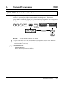
2.14
Location of Optional Cards
The location of the optional cards is shown below.
Precaution
To protect the printed circuit boards (P-boards) from static electricity, do not
touch parts on the P-boards in the main unit and on the optional cards. If
accessing the parts is required, wear a grounding strap.
3-CO Line and 8 Ext
Expansion Card
(KX-TA30877) or
8 SLT Extension Expansion
Card (KX-TA30874)
Connector
Doorphone/Door Opener Card
(KX-TA30860) Connector
The front covers are open.
OGM/Fax Detection Card (KX-TA30891) Connector
NOTE:
Power off the system, and unplug the AC cord before installing an
optional card.
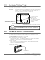
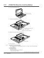
2.15
OGM/FAX Detection Card Installation
An optional OGM/FAX Detection Card (KX-TA30891) can be installed to the system.
The OGM/FAX Detection Card supports the following.
Direct Inward System Access (DISA) with OGM:
One of the system features. An outgoing message greets the external caller and gives
information so that the caller can access an extension(s) directly.
Facsimile detection:
When the system receives a facsimile transmission signal by DISA, it automatically
connects the specified facsimile extension.
1. Remove the 2 screws.
Screws
* The illustrations on this page are a KX-TA308.
Installation
2-17
2.15
OGM/FAX Detection Card Installation
2. Open the bottom front cover.
Bottom front cover
3. Attach the OGM/FAX Detection card.
OGM/FAX Detection Card
(KX-TA30891)
Note
Please do not damage this part.
4. Insert the flat cables to the card connector.
Flat cables
5. Close the cover.
☞
• Required System Programming
See ‘Required System Programming’ in Section 3, Features “Direct Inward System
Access (DISA)”
• Feature References
Section 3, Features
Direct Inward System Access (DISA)
Outgoing Message (OGM)
* The illustrations on this page are a KX-TA308.
2-18
Installation
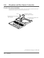
2.16
Doorphone and Door Opener Connection
Four doorphones (KX-T30865) and 4 door openers (user-supplied) can be installed.
Maximum cable length
The maximum length of the doorphone and door opener line cord which connects the system
is as follows.
Diameter of the line
Max. length
Doorphone
22 AWG
180 m {590 feet}
(Station Loop Limit:
24 AWG
113 m {370 feet}
20 Ω)
26 AWG
70 m {230 feet}
Door Opener
22 AWG
180 m {590 feet}
Installing the Doorphone
1. Loosen the screw to open the doorphone unit.
ic
ason
Pan
Screw
2. Attach the base cover to a wall using 2 screws.
Screws
Note Two kinds of screws are included. Please choose the
appropriate one depending on your type of wall.
Type 1: When a doorphone plate has
been fixed to the wall.
Type 2: When you wish to install the
doorphone directly to the wall.
3. Connect the wires to the screws located in the front cover.
To the terminal box
4. Put the doorphone together and re-install the screw.
Installation
2-19
2.16
Doorphone and Door Opener Connection
Doorphone/Door Opener Installation
Attach the optional Doorphone/Door Opener Card to the main unit, connect the cord to the
Doorphone/Door Opener Card connector and secure the screw.
Screw
Doorphone/Door Opener Card
(KX-TA30860)
Doorphone Connectors
Door Opener Terminal
Doorphone/Door Opener Card
Card Connector
* The illustration on this page is a KX-TA308.
2-20
Installation
2.16
Doorphone and Door Opener Connection
Wiring of the Doorphone
1. Connect the Doorphone/Door Opener Card to the terminal boxes using 4-conductor
modular connectors.
2. Connect the wires of doorphones 1 and 3 to the red and green screws on the terminal box.
3. Connect the wires of doorphones 2 and 4 to the yellow and black screws on the terminal
box.
View of Doorphone Connector Jack
Doorphone 2
Doorphone 4
Doorphone 1
Doorphone 3
4-conductor wiring
is required.
Yellow
Red
Black
Green
Panasonic
Panasonic
Doorphone 1
(KX-T30865)
Doorphone 2
(KX-T30865)
4-conductor wiring
is required.
Yellow
Red
Panasonic
Doorphone 3
(KX-T30865)
Black
Green
Panasonic
Doorphone 4
(KX-T30865)
* The illustration on this page is a KX-TA308.
Installation
2-21
2.16
Doorphone and Door Opener Connection
Connecting Door Openers
1. While pressing the button below a hole with a driver, insert the wire from the door opener
into the hole.
Door opener 1
Door opener 4
Door opener 2
Door opener 3
To the door openers
2. Wrap the strap around all of the cords. (☞ 2.20, Securing the Cords)
!
• We recommend using UL1015 wire or the equivalent for wiring.
• The wire should be between 0.4 mm and 1.2 mm {1/64 inch – 3/64 inch} in diameter
including the coating.
D = 0.4 mm – 1.2 mm {1/64 inch – 3/64 inch}
☞
• Required System Programming
Section 4 System Programming
[700]–[702] Doorphone Ringing Assignment — Day/Night/Lunch
[703]–[705] Door Opener Assignment — Day/Night/Lunch
• Feature References
Section 3, Features
Door Opener, Doorphone Call
* The illustrations on this page are a KX-TA308.
2-22
Installation
2.17
Backup Batteries Connection
Two car batteries can be connected to the system as a backup power supply in the event of a
power failure.
1. Attach the cables (KX-A227) and 2 user-supplied car batteries (12 V DC each) as shown
below. Then insert the connector into the side of the system.
Connector
Fuse (250 V / 3.15 A)
Red
Black
Battery Interface
Two Car batteries (12 V DC each)
!
• Make sure of the polarities of batteries and wire.
• Make sure that you do not short the batteries and wires.
Installation
2-23
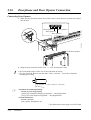
2.18
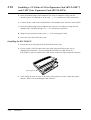
Installing a 3-CO Line & 8 Ext Expansion Card (KX-TA30877)
and 8 SLT Extn. Expansion Card (KX-TA30874)
3-CO Line and 8 Ext Expansion Card Installation (KX-TA30877)
— for KX-TA308 only
To add 3 outside (CO) lines (outside (CO) lines 4 through 6) and 8 extensions (extension
jacks 09 through 16), use an optional 3-CO Line and 8 Ext Expansion Card
(KX-TA30877).
8 SLT Extension Expansion Card Installation (KX-TA30874)
To add 8 extensions (extension jacks 17 through 24), use an optional 8 SLT Extension
Expansion Card (KX-TA30874).
This card can be installed directly to the system or to the KX-TA30877.
!
• Only a single line telephone (SLT) can be connected to extension jacks 17 through 24.
Installing the KX-TA30877 to the KX-TA308
1. Loosen the screws and open the top and bottom front covers.
2. Remove the lower front panel with pliers as shown below. Cut the 6 areas marked
with a circle.
Lower front panel
2-24
Installation
2.18
Installing a 3-CO Line & 8 Ext Expansion Card (KX-TA30877)
and 8 SLT Extn. Expansion Card (KX-TA30874)
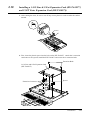
3. After cutting the areas, be sure to cut off any excess plastic in order to make the surface
smooth.
4. First, insert the plastic spacer into the hole on the KX-TA30877. Attach the 2 extension
connectors to the system, install the KX-TA30877 and secure the 2 extension bolts.
Extension Bolts
3-CO Line and 8 Ext Expansion Card
(KX-TA30877)
Extension Connectors
Spacer
Installation
2-25
2.18
Installing a 3-CO Line & 8 Ext Expansion Card (KX-TA30877)
and 8 SLT Extn. Expansion Card (KX-TA30874)
5. Insert the modular plugs of the telephone line cords (2-conductor wiring) into the
modular jacks (CO 4 through 6) on the card. (☞ 2.7, Outside (CO) Line Connection)
6. Connect the line cords to the terminal board or the modular jacks from the Central Office.
7. Insert the modular plugs of the telephone line cords (2 or 4-conductor wiring) into the
modular jacks (JACK 09 through 16). (☞ 2.8, Extension Connection)
8. Wrap the strap around all of the cords. (☞ 2.20, Securing the Cords)
9. Close the covers and secure the screws.
Installing the KX-TA30874
1. Loosen the screws and open the front and bottom front covers.
2. If your system is a KX-TA308, remove the lower front panel in the same way as
installing a KX-TA30877. If you install the KX-TA30874 to a KX-TA616 or a
KX-TA30877, which is connected to a KX-TA308, remove the top front panel with pliers.
Top front panel
3. After cutting the areas, be sure to cut off any excess plastic in order to make the surface
smooth. Please refer to installing the KX-TA30877.
2-26
Installation
2.18
Installing a 3-CO Line & 8 Ext Expansion Card (KX-TA30877)
and 8 SLT Extn. Expansion Card (KX-TA30874)
4. Attach the 2 extension connectors to the system first, install the KX-TA30874 and secure
the 2 screws.
Screws
8 SLT Extension Expansion Card
(KX-TA30874)
Extension Connectors
5. Insert the modular plugs of the telephone line cords (2-conductor wiring) into the
modular jacks (JACK 17 through 24). (☞ 2.8, Extension Connection)
6. Wrap the strap around all of the cords. (☞ 2.20, Securing the Cords)
7. Close the covers and secure the screws.
* The illustration on this page is a KX-TA308.
Installation
2-27
2.18
Installing a 3-CO Line & 8 Ext Expansion Card (KX-TA30877)
and 8 SLT Extn. Expansion Card (KX-TA30874)
Installing the KX-TA30877 and KX-T30874
— for KX-TA308 only
1. Install the KX-TA30877 first and then the KX-TA30874.
Screws
8 SLT Extension Expansion Card
(KX-TA30874)
Extension Bolts
Extension Connectors
3-CO Line and 8 Ext Expansion Card
(KX-TA30877)
Extension Connectors
2-28
Installation
Spacer
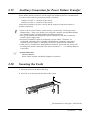
2.19
Auxiliary Connection for Power Failure Transfer
Power failure transfer connects a specific single line telephone (SLT) to selected outside
(CO) lines in the event of system power failure, as follows.
Outside (CO) line 1 – extension (T, R) jack 01
Outside (CO) line 4 – extension (T, R) jack 09
Connection of outside (CO) lines 1 and 4, and the respective extensions require no
auxiliary connection.
!
☞
• In the event of a power failure, system memory is protected by a factory-provided
lithium battery. There is no memory loss except the Camp-on, Saved Number Redial,
Last Number Redial, Call Park and Message Waiting memories.
• The system automatically changes the current connection to the above connection
when the power supply stops.
• Proprietary telephones cannot be used during a power failure. Therefore, we
recommend connecting SLTs in parallel with proprietary telephones connected to
extension jacks 01 and 09, or connecting a KX-T7033 (power failure telephone).
• If DC power is available from backup batteries when AC power fails, the system will
not change the current connection to the above connection. (☞ 2.17, Backup Batteries
Connection)
• Feature References
Section 3, Features
Power Failure Transfer, Paralleled Telephone Connection
2.20
Securing the Cords
1. Insert the rivet into the hole in the strap.
2. Insert the rivet and strap into the hole on the system.
* The illustration on this page is a KX-TA308.
Installation
2-29
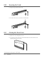
2.20
Securing the Cords
3. Wrap the strap around all of the cords.
4. To remove the rivet, use a screw driver as shown below.
2.21
Closing the Front Cover
1. Replace the covers and tighten the screws.
2. Tie together all of the connected cords and attach them to the wall so that the cords
cannot be pulled out of the system.
* The illustrations on this page are a KX-TA308.
2-30
Installation
2.22
Starting the System for the First Time
1. Set the Power Switch to the “OFF” position.
2. Plug the AC power cord into the system and an AC outlet.
3. Turn the Power Switch on.
(The power indicator will light.)
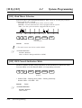
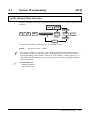
4. Perform the following operation with a proprietary telephone connected to JACK 01.
a) Press the PROGRAM button, or set the MEMORY switch to “PROGRAM” on the
back of the telephone.
b) Press
#.
c) Enter 1234.
d) Enter 999.
e) Press the NEXT (SP-PHONE) button.
f) Press the SELECT (AUTO ANS/MUTE or AUTO ANSWER/MUTE) button until
“All Para” is displayed.
g) Press the STORE (AUTO/STORE or AUTO DIAL/STORE) button.
h) Press the END (HOLD) button.
i) Press the PROGRAM button, or set the MEMORY switch to “SET” on the back of the
telephone.
The system will be initialized with the default values. If the system does not work properly,
please see 2.24, “System Data Clear”.
CAUTION • The system will continue to be powered even if the Power Switch is turned
“OFF”.
• The power supply cord is used as the main disconnect device. Ensure that the
outlet is located/installed near the equipment and is easily accessible.
To AC Outlet
Installation
2-31
2.22
Starting the System for the First Time
Plug Adaptor
The plug adaptor (included) is to be used if the power plug will not fit your socket.
Assemble as shown below, using the plug which fits your socket. In this case, be sure to
connect the frame of the main unit to ground because the ground line in the power cable
cannot be used.
To Power Outlet
Power Plug
2-32
Installation
Plug Adaptor
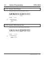
2.23
System Restart
After starting the system, if the system does not operate properly, restart the system.
Before restarting the system, try the system feature again to confirm whether there definitely
is a problem or not.
System Restart causes the following.
• Camp-on is cleared.
• Calls on Hold are terminated.
• Calls on Exclusive Hold are terminated.
• Calls in progress are terminated.
• Call Park is cleared.
• Message Waiting is cleared.
• Last Number Redial is cleared.
• Saved Number Redial is cleared.
Other data is not cleared by System Restart.
1. Turn the Power Switch “OFF” and then “ON”.
!
• If the system still does not operate properly, please see 2.24, “System Data Clear”.
Installation
2-33
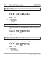
2.24
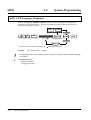
System Data Clear
When the system does not operate properly after restarting, you can clear the programming
data stored in the system. The system will restart with the default settings.
First, try system program [999] “System Data Clear” by following step 4 in 2.22, “Starting
the System for the First Time”. If the system still does not operate properly, please follow
the procedure below.
1. Slide the System Clear Switch to the “CLEAR” position.
2. Press the Reset Button.
3. Return the System Clear Switch to the “NORMAL” position before the power indicator
stops flashing.
(The power indicator will flash for about 10 seconds.)
Reset Button
CLEAR/NORMAL
System Clear Switch
CAUTION • Before touching the System Clear Switch and Reset Button, put on a
grounding strap.
!
☞
• After pressing the Reset Button, return the System Clear Switch to the “NORMAL”
position in step 3 before the power indicator stops flashing. Otherwise, the system will
not clear.
• Feature Reference
Section 3, Features
System Data Default Set
* The illustration on this page is a KX-TA308.
2-34
Installation
Section 3
Features
A
3
Features
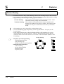
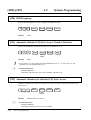
Absent Message Capability
Allows an extension user to set a message which will be displayed at the calling extension
to show the reason for the called extension’s absence. One of 6 messages can be
programmed as desired, which are available for any telephone (single line telephone or
proprietary telephone). Setting or canceling a message can be done by individual extension
users but only callers using a proprietary telephone with a LCD can see the message.
!
☞
• The 6 messages are shown below. “%” means a parameter to be entered when assigning
a message at an extension.
(1) Will Return Soon
(2) Gone Home
(3) At Ext %%% (extension number)
(4) Back at %% : %% AM (or PM) (hour : minute)
(5) Out Until %%/%% (month / day)
(6) In a Meeting
• An extension user can only select one message at a time. The selected message is
displayed every time the user goes off-hook.
• Operating Instructions Reference
1.6 Before Leaving Your Desk, “Showing Your Message on the Calling Party’s Display
(Absent Message Capability)”
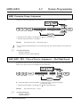
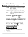
Account Code Entry
An account code is used to identify incoming and outgoing outside calls for accounting and
billing purposes. The account code is appended to the SMDR call record. For incoming
outside calls, an account code is optional. For outgoing outside calls, there are 4 account
input modes programmable in program [605], Option, Forced, Verify–All and Verify–Toll.
Option:
A 4-digit code may be entered during a conversation or within 30 seconds
after a conversation when a record is needed.
Forced:
A 4-digit code must be entered within 5 seconds after an outside (CO) line
is seized. The code can be any number.
Verify–All: Enables to make an outside call if the code entered within 5 seconds after an
extension user seizes an outside (CO) line is the same as one of the account
codes programmed in [310].
Verify–Toll: Enables to override toll restriction temporarily by entering one of the
account codes programmed in [310] within 5 seconds after an outside (CO)
line is seized. Calls with COS numbers 3 through 5 will be treated as calls
with COS number 2. Calls with COS numbers 1 and 2 will not be affected.
3-2
Features
3
A
Features
☞
• Required System Programming
[310] Account Codes
[601]-[603] TRS – Class of Service Assignment — Day/Night/Lunch
[605] Account Code Entry Mode
[805] SMDR Account Code Selection
• Related Feature References
Station Message Detail Recording (SMDR),
Toll Restriction Override by Account Codes
• Operating Instructions Reference
1.7 Useful Features, “Calling with Account Codes (Account Code Entry)”
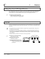
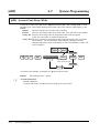
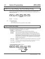
Alternate Calling – Ring/Voice
This system offers a proprietary telephone user 2 types of intercom calling, Voice Call mode
and Tone (ring) Call mode. “Voice Call” informs the called party of an incoming call with
the calling party’s voice, while “Tone Call” uses a ring tone. A proprietary telephone user
can select “Voice Call” or “Tone Call” in the Proprietary Telephone Settings. If the user
selects “Voice Call”, the calling party can talk to the user immediately after the confirmation
tone. The calling party can switch the pre-set mode at the called extension, from “Voice
Call” to “Tone Call” or vice versa, by pressing “ ” after dialing the extension number.
!
☞
• A rotary telephone user cannot change the pre-set mode at the called extension.
• Operating Instructions References
1.2 Proprietary Telephone Settings, “Customizing Your Telephone Functions”,
Intercom Alert Assignment
1.7 Useful Features, “Alternate Calling – Ring/Voice”
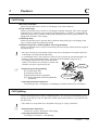
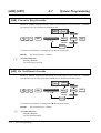
Automatic Callback Busy (Camp-On)
When the selected outside (CO) line or dialed extension is busy, the system will
automatically notify an extension user with a callback ringing when the line becomes
available. When the user answers the callback ringing:
For an extension:
The called extension starts ringing without dialing.
For an outside (CO) line: The line is seized.
☞
• Operating Instructions Reference
1.3 Making Calls, “Making Your Telephone Ring Back Automatically When a Line
Becomes Free (Automatic Callback Busy – Camp-On)”
Features
3-3
A
3
Features
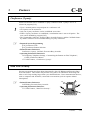
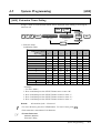
Automatic Outside (CO) Line Access Number
An Automatic Line Access number (9 or 0) can be programmed. When an extension user
dials an Automatic Line Access number before a telephone number, an available outside
(CO) line from the assigned lines in program [419] is seized automatically. If “0” is selected
in program [121], the operator call will be “9” automatically. If “9” is selected in program
[121], the operator call will be “0” automatically.
☞
• Related Feature References
Operator Call, Outside Calling
• Required System Programming
[121] Automatic Outside (CO) Line Access Number Selection
[419] Automatic Designated Outside (CO) Line Access
Automatic Route Selection (ARS)
The system automatically selects the least expensive route available at the time a long
distance call is made on the outside (CO) line which has enabled the ARS feature. It is not
necessary to dial the access code of the least expensive carrier.
1. Normal Use
To make a call via the least expensive carrier, the dialed number is modified. The following
are modification examples.
Example 1 (Long distance call using Route 1):
[350] “ARS Selection”: Enable
[351] “Route 1 Selection Codes (Leading Digit)”: 9, 0
[355] “Route 1 Exception Codes”: 07
[360] “ARS Modification – Removed Digits”: 0 (No deletion)
[361] “ARS Modification – Added Number”: 050 (Code of least expensive carrier for a
long distance call)
<Dialed number>
<Modified number>
93 425 9477
050 93 425 9477
04 123 4567
050 04 123 4567
Example 2 (International call using Route 2):
[350] “ARS Selection”: Enable
[352] “Route 2 Selection Codes (Leading Digit)”: 07
[360] “ARS Modification – Removed Digits”: 2
[361] “ARS Modification – Added Number”: 05000 (Code of least expensive carrier for
an international call)
<Dialed number>
<Modified number>
07 81 92 477 1450
050 00 81 92 477 1450
Example 3 (Long distance call via the first carrier):
[350] “ARS Selection”: Enable
[359] “1st Carrier Selection Code”: 000
<Dialed number>
<Modified number>
000 93 425 9477
93 425 9477
3-4
Features
3
A
Features
2. Special Use
If an extension user always uses the Automatic Line Access number (9 or 0) when making
an outside call and wants to seize the specified outside (CO) line group as below
automatically, refer to the following program assignment.
<Example>
• Outside (CO) line group which connects with the least expensive carrier for a long
distance call (Long distance calls start with“9” or “0”. Carrier code = 050)
• Outside (CO) line group which connects with the least expensive carrier for an
international call (International calls start with “07”. Carrier code = 05000)
• Outside (CO) line group connected with a mobile jack
(Mobile telephone calls start with “6”.)
To specify how to modify the dialed number, and specify an outside (CO) line group
for each route
Program
Address
Route
No.
Route 1
Route 2
Route 3
[351]
[354]
[355]
[358]
9, 0
07
6
07
[360]
[361]
[364]
0 digit
2 digits
0 digit
050
05000
outside line group number 1
outside line group number 1
outside line group number 2
To specify outside (CO) lines in the outside (CO) line groups
Program
Address
Outside (CO)
Line No.
1
2
3
[404] Outside (CO) Line
Group Assignment
[350]
[419] Automatic
Designated
Outside (CO)
Line Access
outside line group number 1
outside line group number 1
outside line group number 2
Enable
Enable
Enable
Enable
Enable
Disable
First
Carrier
Mobile
Jack
KX-TA308
Outside (CO) Line
2
1
Group1
3
Group2
Local Call
Second
Carrier
050 (Long Distance Call)
Third
Carrier
05000 (International Call)
Features
3-5
A
3
Features
Example 5 [Long distance call using Route 1 (outside line group number 1)]:
<Dialed number>
<Modified number>
9 93 425 9477
050 93 425 9477
9 04 123 4567
050 04 123 4567
Example 6 [International call using Route 2 (outside line group number 1)]:
<Dialed number>
<Modified number>
9 07 81 92 477 1450
050 00 81 92 477 1450
Example 7 [Mobile telephone call using Route 3 (outside line group number 2)]:
<Dialed number>
<Modified number>
9 6 123456
6 123456
!
☞
3-6
• System Programming is required to execute this feature.
• If an extension user makes an outside call using the Automatic Line Access number (9 or
0) and the dialed number does not apply to any numbers assigned in programs
[351]–[354], an outside (CO) line which has selected “Enable” in program [419]
“Automatic Designated Outside (CO) Line Access” is automatically seized.
• Required System Programming
[350] ARS Selection
[351]-[354] Routes 1 through 4 Selection Codes (Leading Digits)
[355]-[358] Routes 1 through 4 Exception Codes
[359] 1st Carrier Selection Code
[360] ARS Modification – Removed Digits
[361] ARS Modification – Added Number
[362] ARS Dial Tone Pattern Selection
[363] ARS Interdigit Time
[364] ARS Outside (CO) Line Group
Features
3
A
Features
Flow chart of possible cases and results for ARS calls
Start
A
*1
Is (another) 1 digit dialed within
the ARS Interdigit Time?
No
Yes
*2
Each time a digit is dialed, the system checks the
dialed number (other than Host PBX access codes,
Carrier excepted codes and 1st carrier access code).
Is the dialed number a toll
restriction denied code?
Yes
Reorder tone
No
*3
Yes
Is the dialed number an
emergency call number?
The dialed number is sent
to the Central Office.
No
*4
Yes
Is the dialed number a toll
restriction denied code?
Reorder tone
No
Yes
Does the dialed number include
the 1st carrier access code?
The dialed number (other than the 1st carrier
access code) is sent to the Central Office.
No
*6
*5
Yes
Does the area code match a
Route 1 selection code?
Does the area code
match a Route 1
exception code?
No
*7
No
Removing from
and adding to the
dialed number.
*8
Route 1 is
selected.
Yes
*7
*10
*9
Does the area code match a
Route 2 selection code?
Yes
Does the area code
match a Route 2
exception code?
No
No
Removing from
and adding to the
dialed number.
*8
Route 2 is
selected.
Yes
*11
Yes
Does the area code match a
Route 3 selection code?
*12
Does the area code
match a Route 3
exception code?
No
*7
No
Removing from
and adding to the
dialed number.
*8
Route 3 is
selected.
Yes
*13
Yes
Does the area code match a
Route 4 selection code?
*14
Does the area code
match a Route 4
exception code?
No
*7
No
Removing from
and adding to the
dialed number.
*8
Route 4 is
selected.
Yes
Are 7 digits (other than Host PBX
access codes, Carrier excepted codes
and 1st carrier access code) dialed?
No
Yes
The dialed number is sent
to the Central Office.
*15
Goes to A
Note: The explanation for *1 through *15 is on the next page.
Features
3-7
A-B
3
Features
*1: The ARS Interdigit timer is assigned in program [363] “ARS Interdigit Time”.
*2: The codes are assigned in the following programs.
Host PBX access codes: [403] “Host PBX Access Codes”
Carrier excepted codes: [300] “Carrier Excepted Code Assignment”
1st carrier access code: [359] “1st Carrier Selection Code”.
*3: Emergency call numbers are assigned in program [309] “Emergency Dial Number Set”.
*4: Toll restriction denied codes are assigned in program [302]-[305] “Toll Restriction – Classes 2
through 5 Denied Codes”.
*5: Route 1 selection codes are assigned in program [351] “Route 1 Selection Codes (Leading Digits)”.
*6: Route 1 exception codes are assigned in program [355] “Route 1 Exception Codes”.
*7: Removing digits are assigned in program [360] “ARS Modification – Removed Digits” and
added numbers are in [361] “ARS Modification – Added Number”
*8 The outside (CO) line group(s) assigned in program [364] is (are) automatically seized when
making a call using the Automatic Outside (CO) Line Access number (9 or 0).
*9: Route 2 selection codes are assigned in program [352] “Route 2 Selection Codes (Leading Digits)”.
*10: Route 2 exception codes are assigned in program [356] “Route 2 Exception Codes”.
*11: Route 3 selection codes are assigned in program [353] “Route 3 Selection Codes (Leading
Digits)”.
*12: Route 3 exception codes are assigned in program [357] “Route 3 Exception Codes”.
*13: Route 4 selection codes are assigned in program [354] “Route 4 Selection Codes (Leading
Digits)”.
*14: Route 4 exception codes are assigned in program [358] “Route 4 Exception Codes”.
*15: The system repeats checking until 7 digits are dialed.
Busy Station Signaling (BSS)
When an extension user calls a busy extension, the busy extension will hear a Call Waiting
tone to know that a call is waiting.
!
☞
3-8
• This feature is only available if the called extension has set the Call Waiting feature. If
the Call Waiting feature is activated, the caller will hear a ringback tone. If not, the caller
will hear a reorder tone.
• Related Feature Reference
Call Waiting
• Operating Instructions Reference
1.3 Making Calls, “Sending a Call
Waiting Tone to a Busy Extension
(Busy Station Signaling — BSS)”
Features
She is on the line.
I will send a Call
Waiting tone.
CALL WAITING TONE
I’ve got another call.
Please hold.
3
C
Features
Call Forwarding
Allows an extension user to transfer incoming calls automatically to another extension or to
an external destination. The following types are available.
All Calls:
All incoming calls are forwarded to another extension.
Busy or No Answer:
All incoming calls are forwarded to another extension when
the extension user does not answer within the programmed
time in [202] or when the extension is busy.
To an Outside(CO) Line: Allows an extension user enabled in program [607] to forward
all incoming calls to an external party.
Follow Me:
Allows an extension user to set the Call Forwarding – All
Calls feature from another extension.
!
☞
• Extensions which have already been assigned as
a forwarded destination cannot set the Call
Forwarding feature.
• If the Do Not Disturb (DND) feature has
already been set, setting the Call Forwarding
feature will cancel DND.
• The Call Forwarding – to Outside (CO) Line feature will forward all incoming intercom
calls and certain kinds of incoming outside calls. These outside calls must arrive on
outside (CO) lines whose programming, [414]-[416] “Outside (CO) Line Mode —
Day/Night/Lunch”, is one of the following:
1) DIL
2) DISA1 or DISA2 (only when the call is directly sent to an extension, not
intercepted)
3) UCD (only when the UCD group has one member)
• If a call between 2 outside parties is established by the Call Forwarding – to Outside
(CO) Line feature, the duration of the call is determined by the system timer assigned in
program [205]. An alarm tone is generated to both outside parties 15 seconds before the
timeout. The call will be disconnected at the timeout.
• Required System Programming
[202] Call Forwarding Start Time
[205] Outside-to-Outside (CO-to-CO) Line Duration Time Limit
[607] Call Forwarding to an Outside (CO) Line
• Related Feature Reference
Limited Call Duration
• Operating Instructions References
1.2 Proprietary Telephone Settings, “Customizing the Buttons on Your Telephone”,
FWD/DND (Forward/Do Not Disturb) Button
1.6 Before Leaving Your Desk, “Forwarding a Call (Call Forwarding)”
Features
3-9
C
3
Features
Calling Party Control (CPC) Signal Detection
The Calling Party Control (CPC) signal is a disconnect signal sent from the Central Office
for an outside call. The CPC signal detection is activated by programs [420] and [421].
Program [420] is for incoming outside calls, and [421] is for outgoing outside calls.
☞
• Required System Programming
[420] Calling Party Control (CPC) Signal
[421] CPC Detection for Outgoing Calls
Call Park
Allows an extension user to place a held call into a system parking area. Any extension user
can retrieve the parked call to perform other operations. Up to 10 calls can be parked at the
same time.
!
☞
3-10
• If a parked call is not retrieved within the assigned time in program [200], a ring tone or
an alarm tone will be heard.
• If a parked call is not retrieved within 30 minutes, it will be automatically disconnected.
• This feature is useful when an extension user wants to hold more than one intercom call
with a proprietary telephone, or more than one intercom call or outside call with a single
line telephone.
• During a 5-party conference, this feature cannot be performed.
• Required System Programming
[200] Hold Recall Time
• Related Feature Reference
Conference (5-party)
• Operating Instructions Reference
1.5 During Conversation, “Placing
a Call in System Parking Area
(Call Park)”
Features
Parking zone
3
C
Features
Call Pickup
<Directed Call Pickup>
Allows an extension user to answer a call ringing at any other extension.
<Group Call Pickup>
Allows an extension user to answer a call ringing at another extension, if the call is ringing
within the user’s extension group assigned in program [600]. If “Enable” is selected for an
extension group in [127], persons in the group can pickup calls just by going off-hook, even
though their extension is not ringing.
<Call Pickup Deny>
Allows an extension user to prevent other extensions from picking up a call ringing at the
user’s extension with the Call Pickup feature.
<Call Retrieving from a TAM (Telephone Answering Machine)>
Allows an extension user to answer an incoming call received by a TAM extension assigned
in program [611].
!
• The user can pick up an incoming outside, intercom or doorphone call with the Directed
Call Pickup or Group Call Pickup feature.
• A confirmation tone is sent to the user when the call is picked up with the Directed Call
Pickup or Group Call Pickup feature. The tone can be disabled in program [117].
• If a ringing extension sets the Call Pickup Deny
feature, an extension user will hear a reorder tone
when the user tries to pick up the call.
He’s not in.
I’ll answer it.
☞
• Required System Programming
[117] Call Pickup Tone
[127] Pickup Group Set
Hello.
[600] Extension Group Assignment
Sorry, Mr. Smith is
out of the office.
[611] TAM (Telephone Answering Machine)
Extension
• Operating Instructions Reference
1.4 Receiving Calls, “Picking up a Call Ringing at Another Extension (Call Pickup)”
Call Splitting
Allows an extension user to talk to 2 different parties. If a call is received while the user is
already on the line, the user can place the current call on hold and have a conversation with
the other party.
!
☞
• This feature is not possible for a doorphone call, page or 5-party conference.
• Related Feature References
Conference (5-party), Doorphone Call, Paging
• Operating Instructions Reference
1.5 During Conversation, “Call Splitting”
Features
3-11
C
3
Features
Call Transfer – to Extension
Allows an extension user to transfer a received call, an intercom or an outside call, to
another extension. Two types are available.
Screened Call Transfer: Announces the call to another extension before completing
the transfer.
Unscreened Call Transfer:Immediately releases the call to another extension without an
announcement.
!
☞
• If the destination extension does not answer the call within the assigned time in program
[201], the call will return to the transferring party.
• An outside call can be transferred to an extension by simply pressing a DSS button. It
requires program [005].
• If Music on Hold is enabled, music is sent to the original external caller while being
transferred. Sending a cyclic tone or music on hold can be programmed by program
[111].
• During a 5-party conference, the user cannot transfer a call.
• Required System Programming
[005] One-Touch Transfer Using a DSS Button
[111] Hold Music Selection
[201] Transfer Recall Time
• Related Feature References
Conference (5-party), Hold, Music on Hold
• Operating Instructions Reference
1.5 During Conversation, “Transferring a Call to an Extension (Call Transfer – to
Extension)”
Call Transfer – to Outside (CO) Line
Allows an extension user enabled in program [606] to transfer a received call, an intercom
call or an outside call, to an external party.
!
3-12
• If a call between 2 external parties is established using this feature, an alarm tone will be
sent to both parties 15 seconds before the assigned time limit in program [205]. Also, a
ring tone or an alarm tone will be sent to the extension who transferred the call
50 seconds before the timeout. The call will be disconnected at the timeout unless the
extension joins the conversation again.
• A single line telephone user cannot transfer a received call to an external party.
• If Music on Hold is enabled, music will be sent to the original external caller while being
transferred. Sending a cyclic tone or music on hold can be programmed by program
[111].
• To join the conversation again after transferring the call, press the corresponding CO
button. A conference call will be established. This feature is not available for a single
line telephone.
Features
3
C
Features
☞
• Required System Programming
[111] Hold Music Selection
[205] Outside-to-Outside (CO-to-CO) Line Duration Time Limit
[606] Call Transfer to an Outside (CO) Line
• Related Feature Reference
Hold, Music on Hold
• Operating Instructions Reference
1.5 During Conversation, “Transferring a Call to an Outside (CO) Line (Call Transfer –
to Outside (CO) Line)”
Call Waiting
During a conversation, a Call Waiting tone informs an extension user that there is a call
waiting. The user can answer the second call by disconnecting the first call or placing it on
hold. When Call Waiting is enabled, a Call Waiting tone is sent to the user under the
following conditions.
1) When an outside call (except a doorphone
CALL WAITING TONE
call) is received, or
I’ve got another call.
2) When another extension executes the Busy
Please hold.
Station Signaling (BSS) feature.
!
• For proprietary telephone users, a Call Waiting
tone (Tone 1 or Tone 2) can be selected in the Proprietary Telephone Settings. Tone 2
depends on System Programming. Program [423] is for outside calls and program [115]
is for intercom calls.
15 s
Tone 1
Tone 2
Single:
5s
Double:
Triple:
☞
• Required System Programming
[115] Extension Ringing Pattern Selection
[423] Outside (CO) Line Ringing Pattern Selection
• Related Feature Reference
Hold
• Operating Instructions References
1.2 Proprietary Telephone Settings,
“Customizing Your Telephone Functions”, Call Waiting Tone Selection
1.5 During Conversation, “Call Waiting”
Features
3-13
C
3
Features
Conference (3-party)
<Conference>
During a 2-party conversation, an extension user can add a third party to make a 3-party
conference. The maximum number of members of a conference can be programmed in
program [116].
<Conference, Unattended>
When a proprietary telephone user is in a 3-party conference with 2 external parties, the user
can leave the conference to allow the other 2 parties to continue the conversation. This is
called an Unattended Conference. The user may return to the conference, if desired.
!
☞
3-14
• The possible combinations, through System Programming, are 3 extensions, 1 extension
and 2 external parties, or 2 extensions and 1 external party.
• When a 2-party call is changed to a 3-party call or vice versa, a confirmation tone is sent
to all 3 parties. The tone can be disabled by program [105].
• A 3-party call can also be established by the Executive Busy Override feature.
• The duration of an Unattended Conference can be limited in program [205]. The call is
disconnected when the assigned time limit expires unless the extension which leaves the
conference returns to it.
• An Unattended Conference can be established when the extension is allowed to transfer a
call to an outside (CO) line by program [606].
• Required System Programming
[105] Conference Tone
[116] Conference Pattern Selection
[205] Outside-to-Outside (CO-to-CO) Line Duration
Time Limit
[606] Call Transfer to an Outside (CO) Line
• Related Feature References
Limited Call Duration, Executive Busy Override
• Operating Instructions References
1.2 Proprietary Telephone Settings, “Customizing the
Buttons on Your Telephone”,
CONF (Conference) Button
1.7 Useful Features, “Conference (3-party)”
1.7 Useful Features, “Conference, Unattended”
Features
3
Features
C-D
Conference (5-party)
Allows an extension user to establish a 5-party conference when “5 party C-2 E-5” is
selected in program [116].
!
☞
•
•
•
•
Up to 2 external parties can participate in a conference call.
All 5 parties can be extensions.
Only one 5-party conference can be established at one time.
When a 5-party conference is established, a confirmation tone is sent to all parties. The
tone can be disabled by program [105].
• The Unattended Conference, Executive Busy Override features, and the Call Park feature
by another extension are not available during a 5-party conference.
• Required System Programming
[105] Conference Tone
[116] Conference Pattern Selection
• Related Feature References
Conference (3-party), Call Park, Executive Busy Override
• Operating Instructions References
1.2 Proprietary Telephone Settings, “Customizing the Buttons on Your Telephone”,
CONF (Conference) Button
1.7 Useful Features, “Conference (5-party)”
Data Line Security
Prevents an extension user from being interrupted by the Call Waiting and Executive Busy
Override features. This feature also prevents a ring tone or an alarm tone from being sent
when a call is kept waiting longer than a pre-determined time. Data communication devices,
such as computers and facsimiles, connected to an extension jack can operate without
interruptions.
☞
• Related Feature References
Call Waiting, Executive Busy Override
• Operating Instructions Reference
1.7 Useful Features, “Data Line Security”
Features
3-15
D
3
Features
Date and Time Setting
A manager or operator can adjust the current time.
☞
• Required System Programming
[000] Date and Time Setting
• Operating Instructions Reference
1.8 Operator / Manager Service Features, “Date and Time Setting”
Direct In Line (DIL)
Enables an incoming outside call to go directly to a specified extension. This outside (CO)
line can be used by multiple extension users to make a call, but can only be used by one
extension to receive a call. DIL can have a different destination in the day, night and/or
lunch modes.
!
☞
3-16
• If the destination extension is in an extension group which has enabled the Station
Hunting feature in program [100] “Hunting Group Set”, Station Hunting (Terminate or
Circular in program [101] “Hunting Type”) works when the extension is busy.
• Required System Programming
[414]–[416] Outside (CO) Line Mode — Day/Night/Lunch
• Related Feature References
Station Hunting, Time (Day/Night/Lunch) Service
Features
1
4
7
2
5
8
0
3
6
9
1
4
7
2
5
8
0
3
6
9
1
4
7
2
5
8
0
3
6
9
1
4
7
2
5
8
0
3
6
9
3
D
Features
Direct Inward System Access (DISA)
Allows an outside caller to access specific system features as if the caller is an extension in
the system. The caller can have direct access to features such as:
• Placing an incoming call to an extension, extension group or operator. The caller also
has the option of dialing the route for an extension using a 1 digit number (DISA builtin auto attendant number) via DISA calls.
• Calling an external party.
One of the following must be selected in program [511] to have direct access to these
features:
(1) None Security, (2) Trunk (Outside (CO) Line) Security, or (3) All Security.
None Security: Any caller can make outside or intercom calls.
Trunk Security: A pre-assigned DISA security code must be entered to make outside
calls.
All Security:
A pre-assigned DISA security code must be entered to make both
outside and intercom calls.
This prevents the caller from making unauthorized calls. However, when making an outside
call by Call Forwarding – to Outside (CO) Line, the call is allowed (exception).
The DISA feature operates without an optional card installed. If an outgoing message
(OGM) which greets a caller and gives information, or fax detection is required, an optional
OGM/FAX Detection Card must be installed. The system can detect a FAX (CNG) tone
according to program [514]. An OGM can be programmed in program [502] (☞ “Outgoing
Message (OGM)” in this section). When a caller reaches a DISA line, a message will greet
the caller. Two different DISA messages can be recorded by the operator or manager. For
example, one message can be used in day mode and the other in night mode, or they can be
used for different outside (CO) lines. If an optional OGM/FAX Detection Card is not
installed, the caller will hear a short beep instead of the OGM (Internal DISA).
!
• “DISA1” or “DISA2” must be assigned to outside (CO) line(s) as the outside (CO) line
mode in programs [414] through [416].
• After the DISA Delayed Answer Time assigned in program [504] expires and a ringback
tone is returned to the caller, a DISA call will be answered. The caller can dial during the
message or after the tone.
• This system can store up to 10 programmable DISA built-in auto attendant numbers in
program [501]. Each number is 1 digit.
• The DISA built-in auto attendant number may be the same as the first digit of other
numbers (extension number, etc.). To avoid confusion, the system waits for the second
digit for a preprogrammed amount of time in program [517] (default: 2 seconds). If the
timer expires, the system will assume that the first digit is a DISA built-in auto attendant
number.
• Only one OGM/FAX Detection Card can be installed .
• The DISA line can be used to make outside calls, if a security code assigned in program
[512] (if required) has been dialed.
• This system can store up to 4 programmable DISA security codes. Each code should be
different.
• When a wrong DISA security code is entered, 3 beeps will be heard. The call will be
disconnected after 3 failed attempts. If you enter a security code a second and third time,
dialing
is not necessary.
Features
3-17
D
3
Features
• The duration of outside-to-outside (CO-to-CO) line calls can be limited in program [205].
When the specified time expires, both lines are disconnected. A warning tone is sent to
both parties 15 seconds before the time-limit.
• To detect the end of an outside-to-outside (CO-to-CO) line call, CPC Signal Detection
can be assigned. Programs [420] and [421] are required.
☞
3-18
• Connection Reference
2.15 OGM/FAX Detection Card Installation
• Required System Programming
To enable the DISA feature
[414]–[416] Outside (CO) Line Mode — Day/Night/Lunch
[420] Calling Party Control (CPC) Signal
[421] CPC Detection for Outgoing Calls
[500] DISA Incoming Dialing Mode Selection
[501] DISA Built-in Auto Attendant
[502] OGM Mode Selection
[503] FAX Connection
[506] DISA Busy Mode
[510] DISA No Dial Mode
[511] DISA Security Type
[512] DISA Security Codes
[513] Cyclic Tone Detection
[514] FAX Tone Detection
[516] DISA Incoming Assignment
[518] DISA Tone Selection after the Security Code
To set DISA timer values
[205] Outside-to-Outside (CO-to-CO) Line Duration Time Limit
[504] DISA Delayed Answer Time
[505] DISA Waiting Time after OGM
[517] DISA AA Wait Time
[519] DISA OGM Mute Time
To enable the Intercept Routing feature
[408]–[410] Flexible Ringing Assignment — Day/Night/Lunch
[507] DISA Intercept Mode
[508] DISA Ringing Time before Intercept
[509] DISA Ringing Time after Intercept
[515] Intercept Time for Internal DISA
• Related Feature References
Intercept Routing, Outgoing Message (OGM), Polarity Reverse Detection,
Station Hunting
Features
3
D
Features
DISA Operation
Calling an extension by following the outgoing message
from an External Party
In None Security Mode
DISA phone no.
Enter the DISA phone number.
extension no.
Ringback tone and
DISA outgoing message
Enter the extension number.
Ring back tone
• You can dial the AA number* instead.
In All Security Mode
DISA phone no.
Enter the DISA
phone number.
DISA security code
Ringback tone
and
DISA outgoing
message
Dial
Enter the pre-assigned
DISA security code.
(4 digits)
.
extension no.
One short
beep
Enter the
extension number.
Ring back
tone
• You can dial the AA number* instead.
Calling an extension without an outgoing message (Internal DISA)
from an External Party
In None Security Mode
DISA phone no.
Enter the DISA phone number.
extension no.
Ringback tone
and
one short beep
Enter the extension number.
Ring back tone
• You can dial the AA number* instead.
In All Security Mode
DISA phone no.
Enter the DISA
phone number.
DISA security code
Ringback tone Dial
and
one short beep
.
Enter the pre-assigned
DISA security code.
(4 digits)
extension no.
One short
beep
Enter the
extension number.
Ring back
tone
• You can dial the AA number* instead.
AA number*: A DISA built-in auto attendant number assigned in program [501] “DISA Built-in Auto
Attendant”.
Features
3-19
D
3
Features
Calling an external party by following the outgoing message
from an External Party
In None Security Mode
DISA phone no.
Enter the DISA phone number.
line acccess code
Ringback tone and
DISA outgoing message
phone no.
Enter the phone number
Dial tone
Enter a
of the external party.
from the
line access code
(9 or 0, or 81 through 86). Central Office
In Trunk Security Mode
DISA phone no.
Enter the DISA
phone number.
line acccess code
DISA security
code
Ringback tone
and
DISA outgoing
message
Dial
.
Enter the
pre-assigned DISA
security code.
(4 digits)
phone no.
One short Enter a
Enter the phone
Dial tone
beep
line access code
number of the
from the
(9 or 0, or 81 through 86). Central Office external party.
In All Security Mode
DISA phone no.
Enter the DISA
phone number.
line acccess code
DISA security
code
Ringback tone
and
DISA outgoing
message
Dial
.
Enter the
pre-assigned DISA
security code.
(4 digits)
phone no.
Dial tone
One short Enter a
Enter the phone
from the
beep
line access code
number of the
(9 or 0, or 81 through 86). Central Office external party.
Calling an external party without an outgoing message (Internal DISA)
from an External Party
In None Security Mode
DISA phone no.
Enter the DISA phone number.
line acccess code
Ringback tone
and one beep
Enter a
line access code
(9 or 0, or 81 through 86).
phone no.
Dial tone
Enter the phone number
from the
of the external party.
Central Office
In Trunk Security Mode
DISA phone no.
Enter the DISA
phone number.
DISA security
code
Ringback tone Dial
and
one short beep
. Enter the
pre-assigned DISA
security code.
(4 digits)
line acccess code
phone no.
Dial tone
One short Enter a
Enter the phone
from the
beep
line access code
number of the
(9 or 0, or 81 through 86). Central Office external party.
In All Security Mode
DISA security
code
DISA phone no.
Enter the DISA
phone number.
3-20
Features
Ringback tone Dial
and
one short beep
. Enter the
pre-assigned DISA
security code.
(4 digits)
line acccess code
phone no.
Dial tone
One short Enter a
Enter the phone
from the
beep
line access code
number of the
(9 or 0, or 81 through 86). Central Office external party.
3
D
Features
Flow chart of possible cases and results for DISA calls
An outside line call is made.
*1
The caller reaches the DISA line.
With optional
OGM/FAX Detection Card
Without optional
OGM/FAX Detection Card
(Internal DISA)
@@@@@@@@e?
@@@@@@@@e?@@@@@@@@?e@@@@@@@@e?@@@@@@@@?e@@@@@@@@e?@@@@@@@@?e@@@@@@@@e?@@@@@@@@?e@@@@@@@@e?@@@@@@@@?e@@@@@@@@e?@@@@@@@@?e
@@@@@@@@e?
@@@@@@@@e?@@@@@@@@?e@@@@@@@@e?@@@@@@@@?e@@@@@@@@e?@@@@@@@@?e@@@@@@@@e?@@@@@@@@?e@@@@@@@@e?@@@@@@@@?e@@@@@@@@e?@@@@@@@@?e@@@@@@@@
@@@@@@@@
@@h?
@@
@@h?
@@
@@h?
@@
@@h?
@@
@@h?
@@
@@h?
@@
@@@@@@@@e?
@@@@@@@@e?@@@@@@@@?e@@@@@@@@e?@@@@@@@@?e@@@@@@@@e?@@@@@@@@?e@@@@@@@@e?@@@@@@@@?e@@@@@@@@e?
@@@@@@@@e?
@@@@@@@@e?@@@@@@@@?e@@@@@@@@e?@@@@@@@@?e@@@@@@@@e?@@@@@@@@?e@@@@@@@@e?@@@@@@@@?e@@@@@@@@e?@@@@@@@@
@@@@@@@@
@@h?
@@
@@h?
@@
@@h?
@@
@@h?
@@
@@h?
@@
@@h?
@@
@@
@@
@@
@@
@@
@@
@@
@@
@@
@@
@@
@@
@@
@@
@@
@@
@@
@@
@@
@@
@@
@@
@@
@@
@@
@@
@@
@@
@@
@@
@@
@@
@@
@@
@@
@@
@@
@@
@@
@@
One short beep *2
@@
@@
@@
@@
@@
@@
@@
@@
@@g
@@g
@@g
@@g
@@g
@@g
@@@@@@@@
@@@@@@@@
?@@@@@@@@?e@@@@@@@@e?@@@@@@@@?e@@@@@@@@e?@@@@@@@@?e@@@@@@@@e?@@@@@@@@?e@@@@@@@@e?@@@@@@@@?e@@@@@@@@e?@@@@@@@@?e@@@@@@@@
?@@@@@@@@?e@@@@@@@@e?@@@@@@@@?e@@@@@@@@e?@@@@@@@@?e@@@@@@@@e?@@@@@@@@?e@@@@@@@@e?@@@@@@@@?e@@@@@@@@e?@@@@@@@@?e@@@@@@@@
?@@
?@@
?@@
?@@
?@@
?@@
?@@@@@@@@
?@@@@@@@@
@@
@@
@@
@@
@@
@@
@@
@@
OGM
@@
@@
@@
@@
@@
@@
@@
@@
*13
@@g
?@@
@@g
?@@
@@g
?@@
@@g
?@@
@@g
?@@
@@g
?@@
@@@@@@@@ ?@@@@@@@@?e@@@@@@@@e?@@@@@@@@?e@@@@@@@@e?@@@@@@@@?e@@@@@@@@e?@@@@@@@@?e@@@@@@@@e?@@@@@@@@ ?@@@@@@@@
@@@@@@@@ ?@@@@@@@@?e@@@@@@@@e?@@@@@@@@?e@@@@@@@@e?@@@@@@@@?e@@@@@@@@e?@@@@@@@@?e@@@@@@@@e?@@@@@@@@ ?@@@@@@@@
C
*3
*14
*18
Cyclic tone,
CPC signal
*15
Nothing is dialed.
A number is dialed. *4
The call is sent to
the fax extension.
*5
Is a security
code required?
All
What is the security type?
Yes
Disconnect
Trunk or None
Is Intercept Routing employed? *16
No
The security
code is entered.
FAX (CNG) tone
Busy tone
Yes
No
One
short beep
The code is correct.
*6
Make an outside call.
The call is sent to
another extension.
*17
The code is incorrect.
A
Reorder tone
The call reaches the destination.
Disconnect.
Answered.
*7
Disconnect.
Answered.
Answered.
*9
The destination
extension(s) is(are) busy.
The call is not answered.
B
The call is not
answered.
The call is not
answered for
40 seconds.
Disconnect.
Is Intercept Routing employed? *8
Yes
Disconnect.
What is the DISA *10
Busy Mode?
No
The call is sent to
another extension.
Goes to A
Disconnect
Busy tone
Call Waiting
DISA2
The other
OGM is heard.
*11
Disconnect.
Goes to C *12
Answered.
The call is not
answered.
Goes to
B
Note: The explanation for *1 through *18 is on the next page.
Features
3-21
D
3
Features
*1: The DISA Delayed timer starts. This is the time between a call reaching the system and being
received. The time is assigned in program [504].
*2: When the assigned time period in program [519] expires, the system sends a short beep to the
caller.
*3: The Intercept Timer for Internal DISA starts. This is the time the system waits for the number
sent by the caller. If nothing is entered by the caller during this time, the system will regard it
as “Nothing is dialed.” The time is assigned in program [515].
*4: The system can accept the following numbers:
• 100 through 199 as an extension number.
• 81 through 86 as an outside (CO) line group line access number.
• 9 as an automatic line access number when “Without AA” is assigned in program [500].
Even if “With AA” is assigned, 9 is regarded as the automatic line access number if nothing
is assigned to “9” in program [501]. In case “9” is assigned as the operator call number in
program [121] “Automatic Outside (CO) Line Access Number Selection”, 9 is regarded as
the operator call number instead of an automatic line access number.
• 0 as the operator call number when the operator is assigned in program
[008] “Operator Assignment” and “Without AA” is assigned in program [500]. Even if
“With AA” is assigned, 0 is regarded as the operator call number if nothing is assigned to
“0” in program [501]. If “0” is assigned as an automatic line access number in program
[121], 0 is regarded as an automatic line access number instead of the operator call number.
• 0 through 9 as a built-in auto attendant number when “With AA” is assigned in program
[500]. The DISA AA Wait timer starts after receiving the first 1-digit number. If the timer
expires, the system will assume that the first digit is an AA number. The time is assigned in
program [517].
*5: A security code is necessary when program [511] is assigned as follows.
• All Security –
The system waits for a security code dialed after “ ”. When the
security code matches a code programmed in [512], the system accepts
the numbers after the code.
• Trunk Security – The caller can access an outside (CO) line if the security code matches a
code programmed in [512]. The caller can access other destinations
without the security code.
If the entered number is the same as one of the security codes, a short beep will be heard.
The short beep can be disabled by program [518]. If the number is wrong,
3 beeps will be heard. The call will be disconnected after 3 failed attempts.
*6: The caller must enter the desired telephone number after hearing a dial tone from the Central
Office.
*7: The DISA Ring Timer Before Intercept starts. The destination telephone(s) will ring for the
time programmed in [508].
*8: The system treats the call according to program [507] as follows.
• Disconnect – The call is disconnected.
• Intercept –
The call is sent to the extensions programmed in [408]-[410] “Flexible
Ringing Assignment – Day/Night/Lunch”.
If the call is still not answered within the time programmed in [509], it will be disconnected.
3-22
Features
3
D
Features
*9: If the destination extension belongs to a hunting group and all extensions in the group are busy,
the system will check the DISA Busy Mode. If the destination is a DISA ring group, the DISA
Busy Mode will not work for the call. The system regards the call as unanswered.
*10: The DISA Busy Mode is selected in program [506]. There are 3 modes as follows.
• Disconnect –
The caller hears a busy tone and a call is disconnected.
• Call Waiting – The destination extension hears a call waiting tone if they have enabled
Call Waiting.
• DISA2 –
If “MODE2” is assigned in program [502] and a message is recorded in
OGM2, the caller will hear the message and the system waits for the new
destination.
*11: The DISA Ring Timer Before Intercept starts. The destination telephone(s) will ring for the
time programmed in [508].
*12: In this case, the system disregards the security type and does not accept a line access code. If
nothing is recorded in OGM2 or OGM2 is used for another caller, the caller will hear a busy
tone and the call is disconnected.
*13: The OGM is sent to the caller according to programs [414]–[416] and [502] when the
assigned time in program [519] expires. If an OGM is not recorded, the DISA Wait Timer
After OGM programmed in [505] starts immediately.
When the system detects a FAX (CNG) tone while the OGM is being sent, the call is sent to
the FAX extension assigned in program [503]. When the system detects a cyclic tone or CPC
signal while the OGM is being sent, the call is disconnected.
*14: The DISA Wait Timer After OGM starts. The system waits for a number from the caller
during the time assigned in program [505]. When the system detects a FAX (CNG) tone
during the programmed time, the call is sent to the FAX extension. When the system detects a
cyclic tone or CPC signal during the programmed time, the call is disconnected.
*15: After the DISA Wait Timer After OGM or the Intercept Timer for Internal DISA expires, the
system regards that nothing was dialed.
*16: The system treats the call according to program [510] as follows.
• Disconnect – He call is disconnected.
• Intercept –
The call is sent to the extensions programmed in [408]-[410]. If all
extensions are assigned to “Disable”, the call will be disconnected.
*17: The DISA Ring Timer After Intercept starts. The destination telephone(s) will ring for the
time programmed in [509]. If the call is not answered during the programmed time, the call
will be disconnected.
*18: The FAX extension assigned in program [503] receives the call. When the extension is busy,
the system sends a busy tone to the sending FAX. If the call is not answered after 40 seconds,
the call will be disconnected.
Program [514] sets how many times the FAX (CNG) tone must be detected before the system
recognizes the incoming signal as facsimile data.
Features
3-23
D
3
Features
Display Contrast Adjustment
(KX-T7330/KX-T7030/KX-T7130/KX-T7033 only)
Allows a display proprietary telephone user to adjust the display contrast with the
CONTRAST selector.
☞
• Operating Instructions Reference
1.2 Proprietary Telephone Settings, “Display Contrast Adjustment”
Distinctive Dial Tones
An extension user will hear 3 types of dial tone patterns which give information about the
features activated on the telephone.
Dial Tone 1: This is a normal dial tone. None of the features listed in Dial Tone 2 are
activated.
1s
Dial Tone 2: Sent when any of the following features are set.
• Absent Message Capability
• Background Music (BGM)
(for proprietary telephones only)
• Call Forwarding
• Call Pickup Deny
• Data Line Security
• Do Not Disturb (DND)
• Electronic Station Lockout
• Message Waiting
(for proprietary telephones only)
• Pickup Dialing
• Remote Station Lock Control
(for single line telephones only)
• Timed Reminder
1s
Dial Tone 3: Sent when making an Account Code Entry and answering a Timed
Reminder call. Also sent when going off-hook with a single line telephone
which has a message in a Voice Processing System.
1s
☞
3-24
• Operating Instructions Reference
1.7 Useful Features, “Distinctive Dial Tones”
Features
3
D
Features
Do Not Disturb (DND)
<Do Not Disturb (DND)>
Allows an extension user to prevent other parties from disturbing them. The extension will
not receive intercom or outside calls.
<Do Not Disturb (DND) Override>
Allows an extension user enabled in program [609] to call an extension which has set the Do
Not Disturb (DND) feature.
!
☞
• If your proprietary telephone (PT) is not supplied with the FWD/DND button, it can be
assigned to a flexible CO button in the Proprietary Telephone Settings.
• DND does not work for the following calls: Hold recall or Timed Reminder.
• A PT user in the DND mode can answer a call by pressing the corresponding flashing
button.
• If the Call Forwarding feature has already been set, setting the DND feature will cancel
Call Forwarding.
• Required System Programming
[609] Do Not Disturb Override
• Related Feature References
Call Forwarding,
Timed Reminder
• Operating Instructions References
1.2 Proprietary Telephone Settings,
“Customizing the Buttons on Your Telephone”,
FWD/DND (Forward/Do Not Disturb) Button
1.7 Useful Features, “Rejecting Incoming Calls (Do Not Disturb — DND)”
1.7 Useful Features, “Calling an Extension which Denies Receiving Calls
(Do Not Disturb Override)”
E
TON
DND
Door Opener
Up to 4 Door Openers can be connected to the system. The door can be unlocked by a preassigned extension users in programs [703]-[705].
Could you please
open the door?
Pa
nas
oni
c
Just a moment
please.
!
• An optional Doorphone/Door Opener Card must be installed to the system and a usersupplied door opener to the door to be opened. Four openers can be installed.
• The door opener will open the door even if a doorphone is not installed.
• The door opener timer can be modified in program [709].
Features
3-25
D
3
☞
Features
• Connection Reference
2.16 Doorphone and Door Opener Connection
• Required System Programming
[703]–[705] Door Opener Assignment — Day/Night/Lunch
[709] Door Opener Time
• Related Feature Reference
Doorphone Call
• Operating Instructions Reference
1.7 Useful Features, “Door Opener”
Doorphone Call
Up to 4 Doorphones (KX-T30865) can be installed. If a visitor presses the doorphone
button, a pre-assigned extension user in programs [700]-[702] can answer the call and talk to
the visitor. Any extension user can call a doorphone. The doorphones are also used for the
Room Monitor feature.
!
☞
3-26
• An optional Doorphone/Door Opener Card must be installed to the system and a
doorphone. Four doorphones can be installed.
• Doorphone 1 and 2 cannot be used simultaneously. When one is in use, an extension user
cannot have a conversation with the other. Doorphone 3 and 4 are the same.
• An access tone can be programmed in [707] to be sent to a monitored doorphone before
room monitoring starts.
• The ring tone from the doorphone call is programmable in [706].
• Connection Reference
2.16 Doorphone and Door Opener Connection
• Required System Programming
[700]–[702] Doorphone Ringing Assignment — Day/Night/Lunch
[706] Doorphone Ringing/Tone Pattern Selection
[707] Doorphone Access Tone Selection
[708] Doorphone Ringing Time
• Related Feature References
Door Opener, Room Monitor
• Operating Instructions References
1.7 Useful Features, “Room Monitor”
1.7 Useful Features, “Doorphone Call”
Features
3
Features
D-E
DSS Console
The Direct Station Selection (DSS) Console provides direct access to extensions, a busy
lamp display, as well as 16 PF (Programmable Feature) buttons.
The DSS Console must be programmed to work with a proprietary telephone (PT). The jack
number of the DSS Console and its associated PT are assigned in programs [003] and [004].
Up to 2 consoles can be installed per system.
If a feature like One-Touch Dialing is assigned to a DSS button or PF button, accessing the
feature can be done easily by pressing the corresponding button. This is very useful for an
operator or manager. Refer to the Operating Instructions for more details.
!
☞
• Programming the DSS and PF buttons can be done only from the paired telephone.
• Indicating the Forward (FWD) or Do Not Disturb (DND) status of corresponding
extensions using a DSS button indication is programmable in [112].
• Connection Reference
2.8 Extension Connection
• Required System Programming
[003] DSS Console Port Assignment
[004] Paired Telephone Assignment for DSS Console
[112] DSS Console Indication Mode
• Operating Instructions Reference
1.9 DSS Console Features
Emergency Call
Allows an extension user to access a pre-assigned emergency number which can be dialed
regardless of any restrictions.
!
☞
• Up to 5 emergency numbers can be stored.
• An emergency call is allowed even in the following cases;
— in Account Code Modes (Verify–All and Forced modes),
— in any toll restriction COS number, and
— in Electronic Station Lockout.
• Required System Programming
[309] Emergency Dial Number Set
• Related Feature References
Account Code Entry, Toll Restriction, Station Lock
• Operating Instructions Reference
1.3 Making Calls, “Making Emergency Calls (Emergency Call)”
Features
3-27
E
3
Features
Executive Busy Override
<Executive Busy Override – Extension>
Allows an extension user enabled in program [608] to interrupt an existing intercom call. A
3-party conference will be established.
<Executive Busy Override – Outside (CO) Line>
Allows a proprietary telephone user enabled in program [608] to interrupt an existing outside
call or add a third party. A 3-party conference will be established.
<Executive Busy Override Deny>
Allows an extension user to prevent other extension users from interrupting their
conversation.
!
☞
• The Executive Busy Override feature will not work if the extension engaged the
conversation has set Executive Busy Override Deny or Data Line Security.
• When a 3-party call is changed to a 2-party call or vice versa, a confirmation tone will be
sent to all parties. This tone can be disabled by program [105].
• Required System Programming
[105] Conference Tone
[608] Executive Busy Override
• Related Feature Reference
Conference (3-party)
• Operating Instructions References
1.3 Making Calls, “Interrupting an Existing Call (Executive Busy Override)”
1.3 Making Calls, “Denying ‘Interrupting an Existing Call’
(Executive Busy Override Deny)”
Extension Button Confirmation
(KX-T7330/KX-T7030/KX-T7130/KX-T7033 only)
Allows a display proprietary telephone user to confirm the values stored in the buttons, such
as the REDIAL button or flexible CO button, by pressing the corresponding button while
on-hook.
☞
3-28
• Operating Instructions Reference
1.7 Useful Features “Extension Button Confirmation (KX-T7330/KX-T7030/
KX-T7130/KX-T7033 only)”
Features
3
E
Features
Extension Group
The system supports 8 extension groups. In an extension group, the following features can
be activated.
• Group Call Pickup: Any member of an extension group can pick up a call directed to
another member in the same group.
• Paging – Group: Any member of an extension group can make a voice
announcement to another group member.
A hunting group, DISA ring group or UCD group is a specific extension group. The
following operation as well as the features above can be activated for a hunting group, DISA
ring group or UCD group.
Hunting Group
An extension group enabled in program [100] “Hunting Group Set” will perform the
Station Hunting feature. See “Station Hunting” in this section.
DISA Ring Group
All extensions in a DISA ring group assigned as an auto attendant destination in
program [501] “DISA Built-in Auto Attendant” will ring simultaneously. Selecting
“DISA1” or “DISA2” in programs [414]–[416] “Outside (CO) Line Mode —
Day/Night/Lunch” is required. Also, you must select “With AA” in program [500]
“DISA Incoming Dialing Mode Selection”.
UCD Group
One extension group assigned as the UCD group in program [520] “UCD Group” can
be the destination of incoming outside calls via the UCD feature. Selecting “UCD” in
programs [414]–[416] “Outside (CO) Line Mode — Day/Night/Lunch” is required.
☞
• Required System Program Address
[600] Extension Group Assignment
• Related Feature References
Call Pickup, Direct Inward System Access (DISA), Paging, Station Hunting,
Uniform Call Distribution (UCD)
Extension Password / System Password
The extension password assigned by the manager (extension jack 01) to each extension can
be used for the Walking COS feature. The system password is used for entering System
Programming and also before assigning the extension password.
☞
• Required System Programming
[002] System Password
• Related Feature References
Walking COS
• Operating Instructions Reference
1.8 Operator / Manager Service Features, “Extension Password Set (Manager only)”
Features
3-29
E-F
3
Features
External Feature Access
Allows an extension user to access special features (e.g. Call Waiting) offered by the Central
Office or host PBX. This is done by placing the current call on hold and sending a flash
signal using either the FLASH button or the feature number. This feature is effective only
during an outside call.
!
☞
• When “MODE2” is selected in program [110] and the FLASH button is pressed for
longer than the time programmed in [418], this feature will not work.
• The flash time must be assigned in program [418] as required by the host PBX or outside
(CO) line.
• Required System Programming
[110] Flash Key Mode
[418] Flash Time
• Related Feature References
Flash, Host PBX Access
• Operating Instructions Reference
1.7 Useful Features, “External Feature Access”
Flash
The FLASH button is used to allow a proprietary telephone user to disconnect the current
call and originate another call without hanging up. This is activated when “MODE2” is
selected in program [110] and the FLASH button is pressed for longer than the time
programmed in [418]. When “MODE1” is selected in program [110], the FLASH button can
be used to access features of the Central Office or host PBX (External Feature Access). It is
performed by putting the current party on hold and sending a flash signal while having an
outside call.
!
☞
3-30
• Assigning the External Feature Access feature to any flexible button is useful when
“MODE 2” was selected in program [110]. This can be done from any extension by
assigning the FLASH button to a One-Touch Dialing button (☞ Operating Instructions,
1.2 Proprietary Telephone Settings, “Customizing the Buttons on Your Telephone”, OneTouch Access for System Features). When the assigned button is pressed, a flash signal
is sent during the programmed time in [418].
• Required System Program Address
[110] Flash Key Mode
[418] Flash Time
• Operating Instructions Reference
1.7 Useful Features, “External Feature Access”
Features
3
F
Features
Flexible Buttons
A proprietary telephone (PT) user can change the flexible buttons on the telephone and DSS
console to certain function buttons. For example, if the telephone has more CO buttons than
available outside (CO) lines, the unused CO buttons may be changed to One-Touch Dialing
buttons, etc.
The 4 types of flexible buttons are as follows:
• Flexible CO Buttons (located on a PT only)
• Flexible DSS Buttons (located on a DSS Console only)
• Programmable Feature (PF) Buttons (located on a PT and DSS Console)
• Flexible MESSAGE Buttons (located on a PT except for the KX-T7055)
Check the required operation first. If the telephone is not provided with the button, assigning
the button can be performed in the Proprietary Telephone Settings.
Function
CO
Programmable Button
DSS
PF
MESSAGE
DSS (Direct Station Selection)
✔
✔
One-Touch Dialing
✔
✔
CONF (Conference)
✔
FWD/DND (Forward/Do Not Disturb)
✔
SAVE
✔
Log-In/Log-Out
✔
Single-CO (S-CO)
✔
Other CO (O-CO)
✔
Group-CO (G-CO)
✔
✔
✔
✔
✔
MESSAGE (Message Waiting)
Day
✔
Night
✔
Lunch
✔
Station Lock
✔
“✔” indicates that the feature is available.
☞
•
Operating Instructions Reference
1.2 Proprietary Telephone Settings, “Customizing the Buttons on Your Telephone”
Features
3-31
H
3
Features
Handset/Headset Selection
(KX-T7330/KX-T7030/KX-T7130/KX-T7033 only)
The system supports the use of headsets with proprietary telephones. Switch the selection
mode before using the headset (optional).
☞
• Operating Instructions Reference
1.2 Proprietary Telephone Settings, “When Using the Headset”
Handsfree Answerback
Allows a proprietary telephone with a speakerphone to answer an intercom call without
lifting the handset. This feature performed by pressing the AUTO ANSWER/MUTE or
AUTO ANS/MUTE button.
!
☞
• This feature does not work for incoming outside calls or doorphone calls.
• Operating Instructions Reference
1.4 Receiving Calls, “Handsfree Answerback”
Handsfree Operation
Allows a proprietary telephone user to dial and talk to the other party without lifting the
handset. Pressing one of the following buttons activates the handsfree mode when the
SP-PHONE/MONITOR button indicator is off:
SP-PHONE button, MONITOR button, INTERCOM button, or CO button.
!
☞
3-32
• The KX-T7350, the KX-T7050 and the KX-T7055 can perform handsfree dialing
operations, etc., but cannot have a handsfree conversation.
• Operating Instructions Reference
1.3 Making Calls, “Handsfree Operation”
Features
3
H
Features
Hold
<Call Hold>
Allows an extension user to place an intercom and/or outside call. The held call can be
retrieved by the user who held it, or by any other extension (Call Hold Retrieve).
With a single line telephone (SLT), either one outside or intercom call can be held at one
time. If an SLT user want to hold both calls, use the Call Park feature. An SLT user can
select how to operate the Call Hold feature by program [104].
<Exclusive Hold>
Allows an proprietary telephone user to prevent other extension users from retrieving their
held call. Only the user who held the call can retrieve it. This feature is not available for an
SLT.
!
☞
• Only one intercom call can be placed on hold. For a proprietary telephone, outside calls
and one intercom call can be placed on hold at the same time.
• If a held call is not retrieved within the assigned time in program [200], the extension
user who held it will hear a ring tone or an alarm tone. If the user is on-hook and their
SP-PHONE/MONITOR button indicator is off, the phone will ring (Hold Recall). If the
user is off-hook or in the handsfree mode, an alarm tone will be sent to the built-in
speaker of a proprietary telephone or the handset receiver of a single line telephone at
15-second interval (Hold Alarm).
If “Disable” is selected in program [200], nothing will be heard.
• If a held outside call is not answered within thirty minutes, it will be automatically
disconnected.
• For outside calls, music is sent to the external party on hold, if available (Music on Hold).
• During a 5-party conference, the Hold feature cannot be activated.
• Required System Programming
[104] Hold Mode Selection
[200] Hold Recall Time
• Related Feature References
Call Park, Music on Hold, Background Music (BGM), Hookswitch Flash
• Operating Instructions References
1.5 During a Conversation, “Placing a Call on Hold (Call Hold)”
1.5 During a Conversation, “Placing a Call on Hold Exclusively (Exclusive Hold)”
1.5 During a Conversation, “Retrieving a Call on Hold (Call Hold Retrieve)”
Features
3-33
H
3
Features
Hookswitch Flash
Flashing the hookswitch is used to allow a single line telephone user to hold a call for
transferring or holding, if the flash time is within the assigned time in program [207]. The
procedure to transfer a call or hold is determined in program [104] “Hold Mode Selection”.
Flashing the hookswitch can be also used to disconnect a call, if the flash time is more than
the assigned time in program [207].
!
☞
• If “MODE 1” was selected in program [207], the system will recognize flashing the
hookswitch as hooking, while a busy tone or reorder tone is sent or during a conversation.
The system will recognize as 1 being dialed in the pulse mode, while a dial tone is sent.
The system can refuse receiving a pulse signal by selecting “Disable” in program [614].
Therefore, even if the hookswitch is flashed during a dial tone, the system will regard it
as hooking.
• Required System Programming
[207] Hookswitch Flash Timing Range Selection
[614] Internal Pulse Detection
Host PBX Access
The system may be installed behind an existing host PBX. This is performed by connecting
a line from the host to an outside (CO) line in the system.
!
☞
• A Host PBX Access code assigned in program [403] is required to access an outside (CO)
line of the host PBX.
• Access to the host PBX during a conversation is also possible (External Feature Access).
• Required System Programming
[403] Host PBX Access Codes
[417] Pause Time
• Related Feature Reference
External Feature Access
To Central Office
Host PBX
3-34
Features
3
I
Features
Intercept Routing
Provides automatic redirection of incoming outside calls via the DISA or UCD feature. The
Intercept Routing feature works in the following 2 cases.
1) When nothing is dialed after a dial tone or OGM is sent to the caller. (The DISA feature
only)
2) When the call is not answered within a programmed time. This is called Intercept
Routing – No Answer (IRNA).
☞
• Required System Programming
[408]–[410] Flexible Ringing Assignment — Day/Night/Lunch
[507] DISA Intercept Mode
[508] DISA Ringing Time before Intercept
[509] DISA Ringing Time after Intercept
[510] DISA No Dial Mode
[523] UCD Busy Mode
[524] UCD Intercept Mode
[525] UCD Ringing Time before Intercept
[526] UCD Ringing Time after Intercept
• Related Feature References
Direct Inward System Access (DISA), Uniform Call Distribution (UCD)
Intercom Calling
Allows an extension user to make a call to another extension.
!
☞
• An extension number and a name can be assigned in programs [009] and [604]. If
assigned, they will be shown on the display proprietary telephone during an intercom call.
• The DSS buttons permit a proprietary telephone user one-touch access to an extension.
The DSS button can be assigned to a flexible CO button in the Proprietary Telephone
Settings.
The DSS buttons on the DSS console can also be used.
• An extension user can press the DSS buttons directly to make an intercom call without
going off-hook. This can be enabled by program [126].
• Required System Programming
[009] Extension Number Assignment
[126] DSS Off-Hook Mode
[604] Extension Name Setting
• Operating Instructions References
1.2 Proprietary Telephone Settings, “Customizing the Buttons on Your Telephone”,
DSS (Direct Station Selection) Button
1.3 Making Calls, “Intercom Calling”
1.9 DSS Console Features, “Initial Settings”, Extension Number Assignment
Features
3-35
L
3
Features
Language Selection
The selected language in program [615] is shown on the LCD display of a proprietary
telephone during operation and Proprietary Telephone Settings, but not used during System
Programming. The selected language in program [806] is used for an SMDR printout.
☞
• Required System Programming
[615] LCD Language Assignment
[806] SMDR Language Assignment
Limited Call Duration
The system disconnects 2 types of outside outgoing calls when a specific timer expires. One
is a call with an external party. The other is an outside–to–outside (CO-to-CO) call using the
Call Forwarding – to Outside (CO) Line, Call Transfer – to Outside (CO) Line, Unattended
Conference feature, or the DISA feature. Limiting the time of the call can be assigned
through System Programming.
!
☞
3-36
• An alarm tone will be sent to both parties 15 seconds before the assigned time limit.
• Required System Programming
[205] Outside-to-Outside (CO-to-CO) Line Duration Time Limit
[212] Outside (CO) Line Duration Time Limit
[613] Outside (CO) Line Duration Time Limit Selection
• Related Feature References
Call Forwarding – to Outside (CO) Line, Call Transfer – to Outside (CO) Line,
Conference (3-party), Direct Inward System Access (DISA)
Features
3
L
Features
Line Access Buttons
A proprietary telephone (PT) user must assign one of the following 3 types of CO buttons to
flexible CO buttons in the Proprietary Telephone Settings. This allows making or receiving
outside calls. The default setting for the flexible CO buttons (CO 1 – CO 6) are Single-CO
(S-CO) buttons. CO 1 corresponds to outside (CO) line 1, CO 2 corresponds to outside
(CO) line 2, etc.
<Group-CO (G-CO) Button>
Receiving or making outside calls is on an outside (CO) line group basis. The outside (CO)
line group is assigned in program [404]. Any incoming call from any outside (CO) line in
the outside (CO) line group arrives at the G-CO button. To make an outside call, the user
can access an idle outside (CO) line in the group by simply pressing the assigned G-CO
button.
<Single-CO (S-CO) Button>
Receiving or making outside calls is done using a specific outside (CO) line. An incoming
call from the specific outside (CO) line arrives at the S-CO button. To make an outside call,
the user can access the specific outside (CO) line by simply pressing the assigned S-CO
button.
<Other-CO (O-CO) Button>
Outside (CO) lines, which are not assigned to an S-CO or G-CO button, can be assigned to a
flexible CO button as the O-CO button. An incoming call on an outside (CO) lines arrives at
the O-CO. To make an outside call, the user simply presses the assigned
O-CO button.
!
☞
• The same outside (CO) line group can be assigned to more than one G-CO button on the
same PT.
• The same line can be assigned to an S-CO button and G-CO button. The
S-CO button has priority.
• Immediate, delayed, no ringing or no incoming calls (disable) can be selected by
programs [408] through [413] on an extension-outside (CO) line basis.
• A ringing pattern can be selected for each outside (CO) line by program [423].
• Required System Programming
[400] Outside (CO) Line Connection Assignment
[404] Outside (CO) Line Group Assignment
[405]–[407] Flexible Outward Dialing Assignment — Day/Night/Lunch
[408]–[410] Flexible Ringing Assignment — Day/Night/Lunch
[411]–[413] Delayed Ringing Assignment — Day/Night/Lunch
[423] Outside (CO) Line Ringing Pattern Selection
• Related Feature References
Ringing Pattern Selection, Outside Calling, Receiving Calls
• Operating Instructions Reference
1.2 Proprietary Telephone Settings, “Customizing the Buttons on Your Telephone”,
Line Access Buttons
Features
3-37
L-M
3
Features
Log-In/Log-Out
Allows an extension user to join (Log-In) or leave (Log-Out) a hunting, DISA ring or UCD
group temporarily. Extensions in the log-out mode will not receive calls by Station Hunting,
DISA or UCD but will receive other calls, not like the Do Not Disturb (DND) feature.
The Log-In/Log-Out button can be assigned to a flexible button in the Proprietary Telephone
Settings. The lighting patterns of the Log-In/Log-Out button on a proprietary telephone and
status are as follows.
Log-In
Off: Log-In mode
Red: Log-Out mode
!
☞
• There should be at least one extension that is in the
Log-In mode in a group.
Log-Out
• Related Feature References
UCD Group
Direct Inward System Access (DISA),
Hunting Group
Extension Group,
DISA Ring Group
Station Hunting, Uniform Call Distribution (UCD)
• Operating Instructions References
1.2 Proprietary Telephone Settings, “Customizing the Buttons on Your Telephone”,
Log-In/Log-Out Button
1.7 Useful Features, “Joining or Leaving a Call Distribution Group (Log-In/Log-Out)”
Message Waiting
Allows an extension user to notify the called extension of a message waiting when the called
extension is busy or does not answer the call. Only a proprietary telephone user with a
MESSAGE button can know there is a message waiting if the LED on the MESSAGE button
lights red. Pressing the lit MESSAGE button can call back the called party. The messages
which are stored in the mailbox of the Voice Processing System can also be heard by
following the Voice Mail prompts after pressing the lit MESSAGE button (Voice Mail
Integration).
!
☞
3-38
• This feature is not available for a proprietary telephone which does not have a MESSAGE
button, such as the KX-T7055.
• Canceling the message can be performed from the extension sending it or from the
extension receiving it.
• Each extension can have a maximum of 8 simultaneous messages.
• Messages are always left at the original extension. They cannot be sent to a Call
Forwarding or Station Hunting destination.
• Operating Instructions References
1.2 Proprietary Telephone Settings, “Customizing the Buttons on Your Telephone”,
Restoring the MESSAGE button
1.7 Useful Features, “Leaving a Message Notification (Message Waiting)”
1.7 Useful Features, “Voice Mail Integration for KX-TVP75/KX-TVP100”
Features
3
Features
M-O
Microphone Mute
Allows a proprietary telephone user to turn off the microphone for privacy.
!
☞
• The user’s voice will only be muted during a handsfree conversation. The user can hear
the other party’s voice during Microphone Mute.
• Operating Instructions Reference
1.5 During a Conversation, “Turning off the Microphone (Microphone Mute)”
Music on Hold / Background Music (BGM)
While an external party is on hold, music is automatically generated.
!
☞
• Operations such as Call Hold and Call Transfer activate Music on Hold.
• A user-supplied external music source, such as a radio, must be connected to the system
when “External” is selected in program [111]. One external music source can be
connected to the system. The music source is used for Music on Hold and/or BGM.
• When “Tone” is selected in program [111], the cyclic tone is used only for Music on
Hold and the external music source is used for BGM.
• Connection Reference
2.10 External Music Connection
• Required System Programming
[111] Hold Music Selection
• Related Feature References
Hold, Call Transfer – to Extension, Call Transfer – to Outside (CO) line,
Uniform Call Distribution (UCD)
• Operating Instructions Reference
1.7 Useful Features, “Turning on the Background Music (BGM)”
One-Touch Dialing
Allows a proprietary telephone user one-touch access to a desired party or system feature.
This is done by storing an extension number, telephone number or a feature number (up to
24 digits) in a One-Touch Dialing button. One-Touch Dialing buttons can be assigned to
flexible buttons in the Proprietary Telephone Settings.
!
• An account code can be stored into a One-Touch Dialing button.
• A number consisting of 25 digits or more can be stored by dividing it and storing it in
2 One-Touch Dialing buttons.
Features
3-39
O
3
☞
Features
• Operating Instructions References
1.2 Proprietary Telephone Settings, “Customizing the Buttons on Your Telephone”
One-Touch Dialing button
1.3 Making Calls, “Dialing by Simply Pressing a Button (One-Touch Dialing)”
1.9 DSS Console Features, “Initial Settings”
1.9 DSS Console Features, “One-Touch Dialing”
1.9 DSS Console Features, “One-Touch Access for System Features”
Operator / Manager Extension
The system supports one operator. Any extension can be designated as an operator in
program [008]. Extension jack 01 is the system manager extension. The extension assigned
as an operator or manager has the ability to perform the following operations.
• Setting the Date and Time
• Canceling the Electronic Station Lockout
• Setting/Canceling the Remote Station Lock
• Setting/Canceling/Confirming the Timed Reminder (Wake-up Call) Remotely
• Recording and Playing the Outgoing Message
• Changing the Day/Night/Lunch Mode
The manager extension can also perform System Programming and the following operation.
• Setting the Extension Password
☞
• Required System Programming
[008] Operator Assignment
• Operating Instructions Reference
1.8 Operator / Manager Service Features
Operator Call
Allows an extension user to call an operator within the system by dialing the feature number
assigned in program [121]. One extension can be assigned as the operator in program [008].
!
☞
3-40
• If an operator is not assigned, this feature is not available and a reorder tone will be
heard.
• Every extension user can reach the operator just by dialing the operator call number (0 or
9) assigned in program [121] “Automatic Outside (CO) Line Access Number Selection”.
• Required System Programming
[008] Operator Assignment
[121] Automatic Outside (CO) Line Access Number Selection
• Related Feature Reference
Automatic Outside (CO) Line Access Number
• Operating Instructions Reference
1.3 Making Calls, “Calling an Operator (Operator Call)”
Features
3
O
Features
Outgoing Message (OGM)
Allows the extension assigned as an operator or manager to record up to 2 outgoing voice
messages (maximum 30 seconds each). This message is played when a caller accesses the
DISA or UCD feature. An optional OGM/FAX Detection Card is required to program the
OGM.
The following are some examples of OGM and flow chart.
Case 1: Receives 2 calls at a time – OGM for DISA.
(Do not want customers to be kept waiting.)
System
Outside Call
Outside Call
OGM1
DISA with
OGM
To the designated destination
OGM2
DISA with
OGM
To the designated destination
OGM1: “This is A company. For the sales division, press 1. For the service
division, press 2. To call the operator, press 0.”
OGM2: Same as OGM 1
Required Settings: [502] “MODE1”
[414]-[416] “DISA1”
Case 2: Uses the OGM in the day, night and lunch modes – OGM for DISA.
System
(In the day mode)
Outside Call
OGM1
To the designated destination
System
(In the night mode)
Outside Call
DISA with
OGM
OGM2
DISA with
OGM
The call is disconnected by assigning
“Disconnect” for DISA2 in program
[510] “DISA No Dial Mode”.
OGM1: “This is A company. For the sales division, press 1. For the service
division, press 2. To call the operator, press 0.”
OGM2: “We are sorry but our office is closed for the day.”
Required Settings: [502] “MODE2”
[414]-[416] “DISA1” for OGM1, “DISA2” for OGM2
Case 3: Uses a different OGM for outside (CO) lines – OGM for DISA.
System
(Outside line 1)
Outside Call
OGM1
To the designated destination
(Outside line 2)
Outside Call
DISA with
OGM
OGM2
DISA with
OGM
To the designated destination
Features
3-41
O
3
Features
OGM1: “This is A company. For the sales division, press 1. For the service
division, press 2. To call the operator, press 0.”
OGM2: “This is B company. To contact Mr. A, press 101. To contact Mr. B, press
102.”
Required Settings: [502] “MODE2”
[414]-[416] “DISA1” for the A company outside (CO) line(s).
“DISA2” for the B company outside (CO) line(s).
Case 4: Uses a different OGM when the line is busy – OGM for DISA.
System
OGM1
DISA with
OGM
To the designated destination
Outside Call
The line is busy.
DISA with
OGM
(If the operator is selected.)
OGM2
To the Operator
OGM1: “This is A company. For the sales division, press 1. For the service
division, press 2. To call the operator, press 0.”
OGM2: “We are sorry. The line is currently busy. If you want to call the operator,
press 0.”
Required Settings: [502] “MODE2”
[414]-[416] “DISA1”
[506] “DISA2”
Case 5: Distributes calls to the UCD group – OGM for UCD.
System
The line is busy.
Outside Call
(When the line is free.)
UCD with
OGM
(When the line is free.)
OGM1
The line is busy.
Outside Call
UCD with
OGM
To the UCD group
OGM2
OGM1: “We are sorry. The line is currently busy. Please hold.”
OGM2: Same as OGM1
Required Settings: [502] “MODE3”
[414]-[416] “UCD”
Case 6: Disconnects a call after the OGM – OGM for UCD.
System
OGM1
Outside Call
UCD with
OGM
The line is busy.
OGM2
The call is disconnected.
OGM1: “We are sorry. The line is currently busy. Please hold.”
OGM2: “We are sorry. The line is currently busy. Please call back later.”
Required Settings: [502] “MODE4”
[414]-[416] “UCD”
3-42
Features
3
O
Features
Case 7: Uses the DISA or UCD feature for outside (CO) lines
– OGM for DISA and UCD.
System
(UCD)
UCD with
OGM
The line is busy.
Outside Call
(When the line is free.)
To the UCD group
OGM1
DISA with
OGM
(DISA)
Outside Call
OGM2
To the designated destination
OGM1: “We are sorry. The line is currently busy. Please hold.” (UCD message)
OGM2: “This is A company. For the sales division, press 1. For the service
division, press 2. To call the operator, press 0.” (DISA message)
Required Settings: [502] “MODE5”
[414]-[416] “DISA1” for outside (CO) line(s) which use the DISA
feature
“UCD” for outside (CO) line(s) which use the UCD
feature
Case 8: Uses the DISA feature when none of the extensions in the UCD group can
answer a call – OGM for UCD.
System
OGM1
Outside Call
UCD with
OGM
The line is busy.
OGM2
The call is sent to the DISA feature.
OGM1: “We are sorry. The line is currently busy. Please hold.”
OGM2: “This is A company. For the sales division, press 1. For the service
division, press 2. To call the operator, press 0.”
Required Settings: [502] “MODE6”
[414]-[416] “UCD”
[523] “Intercept”
!
☞
• An optional OGM/FAX Detection Card is required to program the OGM.
• Connection Reference
2.15 OGM/FAX Detection Card Installation
• Required System Programming
[414]–[416] Outside (CO) Line Mode — Day/Night/Lunch
[502] OGM Mode Selection
[506] DISA Busy Mode
[523] UCD Busy Mode
• Related Feature References
Direct Inward System Access (DISA), Uniform Call Distribution (UCD)
• Operating Instructions Reference
1.8 Operator / Manager Service Features, “Outgoing Message (OGM)”
Features
3-43
O
3
Features
Outside Calling
Allows an extension user to make a call to an external party by using one of the following
line access methods.
<Automatic Line Access>
Allows an extension user to select an available outside (CO) line automatically from the
assigned lines in program [419] by pressing the Automatic Line Access number (9 or 0). For
a proprietary telephone, a Line Access Button assignment (S-CO, G-CO, O-CO) in the
Proprietary Telephone Settings is required. If Idle Line Preference is set on the telephone in
the Proprietary Telephone Settings, the user can access an idle line only by going off-hook.
<Individual Line Access>
Allows a proprietary telephone user to select the desired outside (CO) line by pressing the
CO button assigned as the S-CO button. A Line Access Button assignment (S-CO) is
required before use.
<Outside (CO) Line Group Access>
Allows an extension user to select an idle line within a designated outside (CO) line group.
An outside (CO) line group is assigned in program [404]. To specify an outside (CO) line
group, dial the feature number “8” and the desired outside (CO) line group number
(1 through 6). A proprietary telephone user can also specify an outside (CO) line group by
pressing a G-CO button. A Line Access Button assignment (G-CO) is required before use. If
Idle Line Preference is set on the telephone in the Proprietary Telephone Settings, the user
can access an idle line only by going off-hook.
!
☞
3-44
• Each extension requires System Programming to access outside (CO) lines.
• After an outside (CO) line is seized, the system waits for the assigned time in program
[206] before dialing.
• Required System Programming
[206] Dialing Start Time
[400] Outside (CO) Line Connection Assignment
[404] Outside (CO) Line Group Assignment
[405]–[407] Flexible Outward Dialing Assignment — Day/Night/Lunch
[419] Automatic Designated Outside (CO) Line Access
• Related Feature References
Automatic Outside (CO) Line Access Number
Preferred Line Assignment — Outgoing, Line Access Buttons
• Operating Instructions References
1.2 Proprietary Telephone Settings, “Customizing Your Telephone Functions”,
Preferred Line Assignment — Outgoing
1.2 Proprietary Telephone Settings, “Customizing the Buttons on Your Telephone”,
Line Access Buttons
1.3 Making Calls, “Outside Calling”
Features
3
Features
O-P
Outside (CO) Line Ringing Selection
When an outside call is received at an extension, the user can select whether their extension
will ring or not.
!
☞
• Select “Enable” in programs [408]–[410].
• Required System Programming
[408]–[410] “Flexible Ringing Assignment — Day/Night/Lunch
• Operating Instructions Reference
1.2 Proprietary Telephone Settings, “Customizing Your Telephone Functions”,
Outside (CO) Line Ringing Selection
Paging
Allows an extension user to make a voice announcement to several people at the same time.
The message is announced over the built-in speakers of proprietary telephones and/or the
external pager. The paged person can answer the page (Answering a Page) from any
extension within the system. The following types are available.
All Extensions:
Makes a voice announcement to all extensions over the built-in
speakers of proprietary telephones.
Group:
Makes a voice announcement to the designated extension group over
the built-in speakers of proprietary telephones. An extension group is
assigned in program [600] “Extension Group Assignment”.
External:
Makes a voice announcement over the external pager.
All Extensions & : Makes a voice announcement to all extensions over the built-in
External
speakers of proprietary telephones and the external pager.
!
☞
• An extension user can also transfer a call after paging (Paging and Transfer). Also, pages
can be denied (Paging Deny).
• An external pager (user-supplied) must be connected beforehand. One external pager can
be connected to the system.
• A confirmation tone is sent to the extensions before the voice announcement or
answering.
• A confirmation tone is sent to the external pager before the voice announcement. The
tone to the external pager can be disabled in program [106].
• An extension which has set the Do Not Disturb (DND) or Paging Deny feature, or is in
use cannot be paged.
• Connection Reference
2.9 External Pager (Paging Equipment) Connection
• Required System Programming
[106] External Paging Access Tone
• Related Feature References
Extension Group, Do Not Disturb (DND)
• Operating Instructions Reference
1.5 During a Conversation, “Paging”
Features
3-45
P
3
Features
Paralleled Telephone Connection
Any analog proprietary telephone can be connected in parallel with a single line device, such
as a single line telephone, facsimile and data terminal.
!
☞
• System Programming is required.
• Connection Reference
2.11 Paralleled Telephone Connection
• Required System Programming
[610] Paralleled Telephone Connection
• Related Feature Reference
Power Failure Transfer
• Operating Instructions Reference
1.7 Useful Features, “Parallel Connection of a Proprietary Telephone and Single Line
Telephone (Paralleled Telephone Connection)”
Personal Speed Dialing
Allows an extension user to store up to 10 speed dialing numbers (0 through 9) with a
maximum of 24 digits per number. An extension number, telephone number or feature
number can be stored. For example, storing extension numbers for each room in a house can
be useful. (1 = Living Room, 2 = Kitchen, etc.) To make a call, dial # and the number.
!
☞
3-46
• Proprietary telephone users cannot use this feature if One-Touch Dialing buttons are
assigned to PF buttons. If the user assign a personal speed dialing number, the number
stored in the One-Touch Dialing button will be overwritten and vice versa. PF Buttons
F1 through F10 correspond to the speed dialing numbers as follows.
F1 — 0
F6 — 5
F2 — 1
F7 — 6
F3 — 2
F8 — 7
F4 — 3
F9 — 8
F5 — 4
F10 — 9
• A rotary telephone user cannot use this feature.
• Operating Instructions References
1.3 Making Call, “Dialing with Personal Speed Dialing (Personal Speed Dialing)”
Features
3
P
Features
Pickup Dialing
Allows a single line telephone user to make an outgoing call by going off-hook, if the user
has stored the telephone number (up to 32 digits) beforehand. This feature is also known as
Hot Line.
!
☞
• A rotary telephone cannot program this feature.
• The user can set and cancel this feature.
• If the feature is activated and the user goes off-hook, a dial tone will be generated for the
delay time assigned in program [203] and then dialing will start. During the delay time,
the user can dial another party overriding the Pickup Dialing function.
• Required System Programming
[203] Pickup Dial Delay Time
• Operating Instructions Reference
1.3 Making Call, “Dialing by Simply Going Off-Hook (Pickup Dialing)”
Polarity Reverse Detection
The circuit in the system can detect an outside (CO) line polarity reverse signal from the
Central Office when trying to make an outside call. This detects the start (a called party
goes off-hook) and end (the called party goes on-hook) of an outgoing outside call. The
conversation time can be verified on the SMDR printout using this feature.
When an outside call is received, the circuit can also detect the polarity reverse signal before
ringing.
☞
• Required System Programming
[424] Reverse (Polarity) Circuit Assignment
• Related Feature Reference
Station Message Detail Recording (SMDR)
Features
3-47
P
3
Features
Power Failure Transfer
During a power failure, specific extension telephones are automatically connected to specific
outside (CO) lines. This provides outside (CO) line conversations between the following
extensions and outside (CO) lines.
Outside (CO) line 1 : extension jack 01
Outside (CO) line 4 : extension jack 09
A single line telephone (SLT) can work in case of a power failure. Connect an SLT to the
above extension jack. For more information, refer to the Operating Instructions.
!
☞
• All other conversations, except the above combinations, are disconnected during a power
failure.
• Only an outside (CO) line can have a conversation. All other features do not work.
• We recommend connecting a single line telephone (SLT) in parallel at extension jacks 01
and 09, so that an SLT can be used during a power failure.
• Connection Reference
2.19 Auxiliary Connection for Power Failure Transfer
• Related Feature Reference
Paralleled Telephone Connection
• Operating Instructions Reference
1.7 Useful Features, “Power Failure Transfer”
Preferred Line Assignment — Incoming
!
☞
3-48
A proprietary telephone user can select the method to answer incoming outside calls from
the following 3 line preferences. System Programming and Proprietary Telephone Settings
are required.
No Line Preference:
When an incoming call is received, the extension user must go
off-hook and then press the flashing CO button.
Prime Line Preference: When incoming calls are received at the same time, the user
can receive the call on the preferred outside (CO) line by only
going off-hook.
Ringing Line Preference: When an incoming call is received, the user can receive the
call ringing at their telephone by going off-hook.
• A single line telephone can only set “Ringing Line Preference”.
• Line access button(s) (Single-CO, Other-CO or Group-CO) should be assigned to CO
button(s) beforehand.
• Required System Programming
[408]–[410] Flexible Ringing Assignment — Day/Night/Lunch
[411]–[413] Delayed Ringing Assignment — Day/Night/Lunch
• Related Feature Reference
Line Access Buttons
• Operating Instructions References
1.2 Proprietary Telephone Settings, “Customizing Your Telephone Functions”,
Preferred Line Assignment — Incoming
1.2 Proprietary Telephone Settings, “Customizing the Buttons on Your Telephone”,
Line Access Buttons
Features
3
P
Features
Preferred Line Assignment — Outgoing
A proprietary telephone user can select a desired outgoing line preference to make outside
calls from the following 3 line preferences. System Programming and Proprietary Telephone
Settings are required.
Idle Line Preference: When the user goes off-hook, they are connected to an idle line.
An idle line is automatically selected from the pre-assigned
lines in program [419].
Prime Line Preference: When the user goes off-hook, they are connected to the preassigned line. Assign one prime line beforehand.
No Line Preference:
No line is selected when the user goes off-hook. They must
select a line to make a call.
!
☞
• Line access button(s) (Single-CO, Other-CO or Group-CO) should be assigned to the CO
button(s) beforehand.
• Required System Programming
[400] Outside (CO) Line Connection Assignment
[405]–[407] Flexible Outward Dialing Assignment — Day/Night/Lunch
[419] Automatic Designated Outside (CO) Line Access
• Related Feature Reference
Line Access Buttons
• Operating Instructions References
1.2 Proprietary Telephone Settings, “Customizing Your Telephone Functions”,
Preferred Line Assignment — Outgoing
1.2 Proprietary Telephone Settings, “Customizing the Buttons on Your Telephone”,
Line Access Buttons
Proprietary Telephone Setting Data Default Set
Allows a proprietary telephone user to reset the following Proprietary Telephone Settings to
the default settings.
•
•
•
•
•
☞
Preferred Line Assignment — Outgoing
Preferred Line Assignment — Incoming
Outside (CO) Line Ringing Selection
Intercom Alert Assignment
Call Waiting Tone Selection
• Operating Instructions Reference
1.2 Proprietary Telephone Settings, “Customizing Your Telephone Functions”,
Proprietary Telephone Setting Data Default Set
Features
3-49
P-R
3
Features
Pulse to Tone Conversion
Allows an extension user to change the dialing mode from Pulse to Tone after entering a
telephone number to access services, such as computer telephone services or Voice Mail,
which require tones.
!
• This feature only works for outside (CO) lines which have set “Pulse Mode” or ”Call
Blocking Mode” in program [401].
• Changing from Tone to Pulse is not possible.
☞
• Required System Programming
[401] Dial Mode
• Operating Instructions Reference
1.7 Useful Features, “Pulse to Tone Conversion”
Receiving Calls
Allows an extension user to receive an intercom or outside call by going off-hook. A
proprietary telephone user can also receive a call by pressing the rapid flashing CO or
INTERCOM button, and talk (handsfree mode) if the telephone has the SP-PHONE button.
!
☞
• A proprietary telephone user can select the Line Preference for incoming outside calls.
See “Preferred Line Assignment — Incoming” in this section.
• Required System Programming
[408]–[410] “Flexible Ringing Assignment — Day/Night/Lunch”
[411]–[413] “Delayed Ringing Assignment — Day/Night/Lunch”
• Related Feature Reference
Preferred Line Assignment — Incoming
• Operating Instructions Reference
1.4 Receiving Calls, “Receiving Calls”
Redial
<Automatic Redial>
Allows a proprietary telephone user to redial the last number dialed, and saved number by
the Saved Number Redial feature automatically. This is done by pressing the SP-PHONE or
MONITOR button and the corresponding button. Redial will be repeated automatically the
assigned number of times in program [113] until the called party answers. The interval time
between Automatic Redial is programmed in [114]. If another operation is performed during
Automatic Redial, this function will be canceled. This feature is not available for the
KX-T7055.
<Last Number Redial>
Every extension automatically saves the last telephone number dialed so that the extension
user can make a call to the same party later using a simple operation.
3-50
Features
3
R
Features
<Saved Number Redial>
Allows a proprietary telephone user to save the current external telephone number in the
SAVE button during a conversation, so that the extension user can redial the same party later
using a simple operation. The saved number can be redialed until another number is stored.
A flexible button can be assigned as the SAVE button in the Proprietary Telephone Settings.
☞
• Required System Programming
[113] Automatic Redial Repeat
[114] Automatic Redial Interval Time
• Operating Instructions References
1.2 Proprietary Telephone Settings, “Customizing the Buttons on Your Telephone”,
SAVE button
1.3 Making Calls, “Redialing Automatically (Automatic Redial)”
1.3 Making Calls, “Redialing the Last Number Dialed (Last Number Redial)”
1.3 Making Calls, “Redialing the Saved Number (Saved Number Redial)”
Ringing Pattern Selection
A ringing pattern can be selected depending on the type of call such as an outside call,
intercom call and doorphone call. Available ringing patterns are as follows:
1s
Single:
Double:
Triple:
S-Double:
(Doorphone only)
!
☞
• Private calls can be distinguished from business calls by assigning different ringing per
outside (CO) line. Moreover, by assigning different ringing, intercom calls and
doorphone calls can be distinguished from other calls. Therefore, careful attention should
be applied to all ringing assignments.
• Required System Programming
[115] Extension Ringing Pattern Selection
[423] Outside (CO) Line Ringing Pattern Selection
[706] Doorphone Ringing/Tone Pattern Selection
• Related Feature Reference
Outside (CO) Line Ringing Selection
Features
3-51
R-S
3
Features
Room Monitor
Allows a proprietary telephone user to monitor a room or the front door through another
proprietary telephone or doorphone without them knowing. The access tone will not be sent
to the monitored proprietary telephone when monitoring starts.
!
☞
• The extensions that can be monitored must be programmed in [612] before operation
when using a proprietary telephone.
• If a doorphone is used as a room monitor, the access tone will be heard when monitoring
starts as the default setting. The tone can be disabled in program [707].
• This feature is not available for KX-T7050, KX-T7055 and KX-T7350.
• A single line telephone with a MUTE button can be used for monitoring.
• Required System Programming
[612] Room Monitor Assignment
[707] Doorphone Access Tone Selection
• Related Feature Reference
Doorphone Call
• Operating Instructions Reference
1.7 Useful Features, “Room Monitor”
Secret Dialing
Allows a proprietary telephone user to conceal all or part(s) of a System Speed Dialing
number assigned in program [001] or One-Touch Dialing number assigned to a flexible
button in the Proprietary Telephone Settings which normally appear on the display.
!
☞
3-52
• When storing a number, press the INTERCOM button at the beginning and the end of the
numbers to be concealed.
• One or more parts of a telephone number can be concealed.
• Printing out the concealed number on a SMDR can be assigned in program [803].
• Required System Programming
[001] System Speed Dialing Entry
[803] Secret Speed Dialing/One-Touch Dialing Printing
• Related Feature References
One-Touch Dialing, System Speed Dialing
• Operating Instructions References
1.2 Proprietary Telephone Settings, “Customizing the Buttons on Your Telephone”,
One-Touch Dialing Button
1.7 Useful Features, “Secret Dialing”
Features
3
S
Features
Self-Extension Number Confirmation
(KX-T7330/KX-T7030/KX-T7130/KX-T7033 only)
Allows a display proprietary telephone user to confirm their jack and extension number using
a simple operation.
☞
• Operating Instructions Reference
1.7 Useful Features, “Self-Extension Number Confirmation
(KX-T7330/KX-T7030/KX-T7130/KX-T7033 only)”
Station Feature Clear
Allows an extension user to reset the following station features to the default settings.
• Absent Message Capability
• Automatic Callback Busy (Camp-On)
• Background Music (BGM)
• Call Forwarding
• Call Pickup Deny
• Call Waiting
• Data Line Security
• Do Not Disturb (DND)
• Executive Busy Override Deny
• Log-In/Log-Out
• Message Waiting – (All messages will be erased.)
• Pickup Dialing – (The stored telephone number will be erased.)
• Paging Deny
• Room Monitor
• Timed Reminder
• Voice Mail Integration
☞
• Operating Instructions Reference
1.7 Useful Features, “Canceling the Feature Settings (Station Feature Clear)”
Features
3-53
S
3
Features
Station Hunting
If a called extension is busy, Station Hunting redirects the incoming call to an idle extension
in an extension group in numerical order. Idle extensions are automatically hunted according
to programming. The following 2 hunting types are available.
Circular hunting:
The extensions are hunted one time in numerical order. If all
extensions are busy, a busy tone will be heard.
Terminate hunting: The extensions are hunted until the extension which has the
highest jack number in the group is reached. If all higher order
numbers are busy, the search will end and a busy tone will be
heard.
!
☞
3-54
• One hunting type can be selected for each extension group.
• To leave the hunting group temporarily, use the Log-Out feature. To rejoin, use the
Log-In feature.
• If the called extension has set Do Not Disturb (DND), Call Forwarding or Log-Out,
Station Hunting will skip the extension. However, Station Hunting will not skip the
extension which receives the call first, even if it has set Do Not Disturb (DND) or Call
Forwarding.
Circular Hunting
• Required System Programming
[100] Hunting Group Set
[101] Hunting Type
[600] Extension Group Assignment
• Related Feature References
Call Forwarding
Do Not Disturb (DND)
Extension Group
Log-In/Log-Out
Features
Terminate
Busy Tone
3
S
Features
Station Lock
<Electronic Station Lockout>
Allows an extension user to lock their station so that other users
cannot make outside calls until it is unlocked. Any 4-digit code can
be used to lock and unlock an extension.
<Electronic Station Lockout – CANCEL ALL>
The operator and manager can cancel Electronic Station Lockout of
all extensions at one time.
<Remote Station Lock Control>
The operator and manager are given the privilege of controlling Electronic Station Lockout at
any station by using the DSS console. The operator and manager can see the status of each
extension, locked or unlocked, by the pre-assigned DSS button LED on the DSS console.
For example, this feature is useful for a small hotel or motel when guests are checked out.
!
☞
• The Remote Station Lock Control overrides the Electronic Station Lockout. If the
operator or manager sets Remote Station Lock on an extension that has already been
locked by the extension user, the user cannot unlock it.
• A toll restriction class can be assigned to an extension which has set the Electronic Station
Lockout and Remote Station Lock Control features in program [312] “Toll Restriction –
Station Lock Boundary Class”. Certain types of outgoing outside calls are allowed
depending on the assigned toll restriction class.
• Operating Instructions References
1.6 Before Leaving Your Desk, “Locking Your Telephone (Electronic Station Lockout)”
1.8 Operator / Manager Service Features, “Electronic Station Lockout – CANCEL
ALL”
1.8 Operator / Manager Service Features, “Remote Station Lock”
1.9 DSS Console Features “Initial Settings”, Station Lock Button Assignment
(Operator/Manager only)
Features
3-55
S
3
Features
Station Message Detail Recording (SMDR)
Station Message Detail Recording (SMDR) automatically prints out detailed call information
of outside calls. A printer connected to the Serial Interface (RS-232C) port can be used to
print incoming and outgoing outside calls, as well as print a hard copy of System
Programming. To print out the record of System Programming items that have been
assigned, use program [804] “System Data Dump”. To print the call records, use program
[802] “Incoming/ Outgoing Call Selection for Printing”, which prints out the following
records.
• A record of all outgoing outside calls or outgoing toll calls
• A record of all incoming outside calls
An example of a printed call record:
Date
Time
12/31/98 12:52PM
12/31/98 12:53PM
12/31/98 *12:54PM
12/31/98 1:04PM
12/31/98 1:04PM
12/31/98 1:05PM
12/31/98 1:06PM
12/31/98 1:06PM
12/31/98 1:07PM
12/31/98 2:15PM
12/31/98 2:26PM
12/31/98 2:27PM
12/31/98 3:25PM
•
•
(1)
•
•
(2)
Ext.
CO
103
103
101
103
102
103
103
C-05
103
103
103
116
05
02
02
06
05
01
01
02
01
01
01
05
02
•
•
(3)
•
•
(4)
Dial number
12345678901234567890123456789012
<
incoming
>
<
incoming
>
092. . . 1438
< DISA incoming >
< DISA incoming >
092123456789
0921234567
0921234567
0921234567
F/0927654321
9=0924567123
< UCD Waiting >
•
•
(5)
Duration
Code
00:00'16
00:01'43
00:07'48
00:00'06
00:00'09
00:00'08
00:00'08
00:00'17
00:11'00
00:11'00
00:03'00
00:13'55
00:11'48
....
....
....
4536
.... 0
.... 0
....
.... 2
. . 13
. 101
....
....
....
•
•
(6)
•
•
(7)
Example of the SMDR printout format:
Explanation
(1) Date : shows the date of the call as Month/Day/Year.
(2) Time : shows the time the call was started as Hour: Minute/AM or PM.
“*” indicates a transferred call.
(3) Ext. : shows the extension number, etc. that engaged in the call. “C-xx” indicates an
outside-to-outside (CO-to-CO) call via the DISA feature. The outside (CO) line
which receives a DISA call is shown as xx.
(4) CO : shows the outside (CO) line number used for the call.
(5) Dial number
Outgoing call:
Shows the called party’s telephone number (maximum 32 digits).
Valid digits are 0 through 9, #,
and P (if the PAUSE button
was pressed).
Received call:
Shows <incoming>. An incoming call via the DISA feature is
shown as <DISA incoming>, via the DIL feature is shown as
<DIL incoming>.
3-56
Features
3
S
Features
UCD waiting call: Shows <UCD waiting> for an incoming call via the UCD feature.
When the “UCD waiting call” is answered, it becomes a
“Received call” and a new record is started.
(6) Duration : shows the duration of the call or the UCD call waiting time in
Hours/Minutes/Seconds.
(7) Code: shows the account code appended to the call, account code index number
(e.g.: 13), the extension number which uses the Walking COS feature
(e.g.: 101) or DISA security code status (e.g.: 0). Code “0” indicates a DISA
incoming call without a DISA security code. Codes “1 to 4” indicate a DISA
incoming call with DISA security code 01 to 04 respectively. DISA security
codes are never printed out by SMDR.
!
☞
• This system can store information of up to 64 calls.
• This data is not deleted even when the system is reset.
• If FLASH is manually sent out during a conversation to make another call without
hanging up, etc., a call record will be printed and a new record started. “F/” will be
printed at the beginning of the dial number on the new record.
• When a host PBX code is entered, “=” will be printed between the code and dialed
number.
• The language used for an SMDR printout can be selected in program [806].
• Connection Reference
2.13 Printer and PC Connection
• Required System Programming
[000] Date and Time Setting
[204] Call Duration Count Start Time
[800] SMDR RS-232C Communication Parameters
[801] SMDR Parameter
[802] Incoming/Outgoing Call Selection for Printing
[803] Secret Speed Dialing/One-Touch Dialing Printing
[804] System Data Dump
[805] SMDR Account Code Selection
[806] SMDR Language Assignment
• Related Feature Reference
Language Selection
System Data Default Set
This system can re-initialize the system-programmed data. If all the programmed data is
cleared, the system will reset using the default settings by program [999].
!
☞
• The default setting for each programming item is listed in Section 5.1, Default Values.
• Required System Programming
[999] System Data Clear
• Installation Reference
2.24 System Data Clear
Features
3-57
S-T
3
Features
System Speed Dialing
The system supports 100 System Speed Dial numbers (up to 32 digits) assigned in program
[001] that are available to all extension users. A System Speed Dial number is dialed out
using a simple operation.
Each System Speed Dial number can be assigned a name in program [011]. The assigned
name will be displayed when making a call by using the System Speed Dialing feature. It
will also be displayed when an external caller’s telephone number matches one of System
Speed Dialing numbers and a Telephone Company does not provide the caller’s name.
!
☞
• Toll Restriction for System Speed Dialing can be assigned by program [301].
• A rotary telephone user cannot use this feature.
• Required System Programming
[001] System Speed Dialing Entry
[011] System Speed Dialing Name Setting
[301] Toll Restriction – System Speed Dialing Boundary Class
• Related Feature
Toll Restriction for System Speed Dialing
• Operating Instructions for the Caller ID Card References
Section 1.2, System Features
Caller ID
• Operating Instructions Reference
1.3 Making Calls, “Dialing with System Speed Dialing (System Speed Dialing)”
Timed Reminder
<Timed Reminder>
Allows an extension user to generate an alarm tone at a preset time as a wake-up alarm or a
reminder. The user can set this to be activated once or everyday.
<Timed Reminder, Remote (Wake-Up Call)>
The operator or manager can remotely set, cancel and
confirm the Timed Reminder of the desired extension.
For example, this is useful for a small hotel or motel to
set an extension in a guest room as a wake-up call, or
set an extension in a child’s room by a mother.
☞
3-58
• Operating Instructions References
1.7 Useful Features, “Alarm Setting (Timed
Reminder)”
1.8 Operator / Manager Service Features, “Timed Reminder, Remote (Wake-Up Call)”
Features
3
T
Features
Time (Day/Night/Lunch) Service
The system supports the day, night and lunch operation modes. The system operation for
making and receiving calls can be different for the day, night and lunch modes. The system
operation for toll restriction can be arranged to prevent unauthorized toll calls for each mode.
Time service can be set automatically or manually by program [006].
Changing the Day/Night/Lunch Modes
The day, night and lunch modes can be changed either automatically at an assigned time in
program [007] or manually by the operator or manager at any desired time.
!
☞
• The lunch mode interrupts the day or night mode. After the lunch mode is finished, the day
or night mode starts again.
• If the lunch mode is set using feature number “783#” in the automatic mode, the mode
can only be canceled by using feature number “780#”. This can be useful during
holidays. The day and night modes are automatically changed at the programmed time in
[007] even if feature number “780#” is not entered. These operations can only be done
by an operator or manager.
• The operator and manager can see the status of the mode (day, night or lunch) by the preassigned DSS buttons’ LED on the DSS console. Time service can be changed easily by
pressing the pre-assigned DSS buttons.
• The following programming items will be affected by the time service.
[405]-[407] Flexible Outward Dialing Assignment
[408]-[410] Flexible Ringing Assignment
LUNC
[411]-[413] Delayed Ringing Assignment
H
[414]-[416] Outside (CO) Line Mode
[601]-[603] TRS – Class of Service Assignment
[700]-[702] Doorphone Ringing Assignment
[703]-[705] Door Opener Assignment
• Required System Programming
[006] Time (Day/Night/Lunch) Service Changing Mode
[007] Time (Day/Night/Lunch) Service Start Time
• Operating Instructions References
1.8 Operator / Manager Service Features, “Time (Day/Night/Lunch) Service Setting”
1.9 DSS Console Features, “Initial Settings”, Day, Night and Lunch Buttons
Assignment
Features
3-59
T
3
Features
Toll Restriction
Toll Restriction is a system programmable feature that can prohibit certain extension users
from making unauthorized toll calls.
Every extension is programmed to belong to one of 5 classes of service (COS). Each COS is
programmed to have a toll restriction class for day mode, night mode and lunch mode.
There are 5 toll restriction COS numbers available. Toll restriction COS number 1 is the
highest class and the COS number 5 is the lowest. That is, COS number 1 allows all toll
calls. COS numbers 2 through 5 are used to restrict calls by combining pre-programmed
deny and exception codes shown in the table on the next page.
Denied Codes
An outgoing outside call made by an extension with a toll restriction COS number between 2
and 5 is first checked against the assigned denied codes in program [302]-[305].
If the first digits of the dialed number (not including the line access code) are not found in
the class, the call can be made. Each class can store up to 20 denied codes, each consisting
of 11 digits.
Exception Codes
These codes are used to override a programmed denied code. A call denied by the denied
codes is checked against the selected exception codes assigned in program [306]. If a match
is found, the call can be made.
Up to 80 exception codes, each consisting of 11 digits, can be stored. The available number
of codes depends on the COS number.
!
☞
3-60
• Emergency numbers, such as the police or fire station, should be stored in program
[309] “Emergency Dial Number Set” so that they are excepted from toll restriction.
• If a stored Host PBX access code in program [403] “Host PBX Access Codes” or a stored
carrier code in program [300] “Carrier Excepted Code Assignment” is found in the dialed
number, the subsequent telephone numbers will be checked for toll restriction.
• The interdigit timer assigned in program [208] “Interdigit Time” applies until the toll
restriction check is completed. When the timer expires, an outside outgoing call will be
disconnected while dialing, if “Enable” was selected in program [211] “No Dial
Disconnection”.
• The toll restriction class for a station locked extension can be assigned in program [312]
“Toll Restriction – Station Lock Boundary Class” so that even a station locked extension
can make a local call, etc.
• It is programmable whether the “ ” or “#” the user dials is to be checked or not on the
Toll Restriction code in program [125] “Toll Restriction Check for and #”. This is
useful to prevent unauthorized calls which could be possible through certain Central
Office exchange systems.
• Required System Programming
[301] Toll Restriction – System Speed Dialing Boundary Class
[302]-[305] Toll Restriction – Classes 2 through 5 Denied Codes
[306] Toll Restriction – Exception Codes
[601]-[603] TRS – Class of Service Assignment – Day/Night/Lunch
• Related Feature References
Emergency Call, Toll Restriction for System Speed Dialing
Toll Restriction Override by Account Codes
Toll Restriction – Station Lock Boundary Class
Features
3
T
Features
Combination of denied codes and exception codes
COS No.
Denied Calls
1
No restriction.
2
20 denied codes programmed in [302].
3
4
5
Excepted Calls
No restriction.
80 exception codes (code numbers 01-80)
programmed in [306].
20 denied codes programmed in [302] plus 60 exception codes (code numbers 01-60)
20 denied codes programmed in [303].
programmed in [306].
20 denied codes programmed in [302] plus 40 exception codes (code numbers 01-40)
20 denied codes programmed in [303] plus programmed in [306].
20 denied codes programmed in [304].
20 denied codes programmed in [302] plus 20 exception codes (code numbers 01-20)
20 denied codes programmed in [303] plus programmed in [306].
20 denied codes programmed in [304] plus
20 denied codes programmed in [305].
Flow chart of Toll Restriction
The user makes a toll call.
Is it a System Speed Dialing number?
*1
Yes
No
Yes
*2
Is the COS number higher than the
system speed dialing boundary class?
No or Equal
What is the
COS number?
COS1
COS2 - 5
Is the dialed number found
in applicable denied codes?
Yes
Is the dialed number found in
applicable exception codes?
No
The call is denied. A reorder
tone is returned to the user.
No
*1: System Speed Dialing
numbers are assigned in
Yes
program [001] “System
Speed Dialing Entry”.
*2: The system speed dialing
boundary class is assigned in
program [301] “Toll
The call is allowed.
Restriction – System Speed
Dialing Boundary Class”.
Features
3-61
T
3
Features
Toll Restriction for System Speed Dialing
Calls originated by System Speed Dialing are restricted depending on the combination of the
System Speed Dialing Boundary Class assigned in program [301] and the class of service
(COS) assigned to each extension as follows.
System Speed
Dialing Boundary
Class
COS
No.
A: allowed
☞
3-62
1
2
3
4
5
1
A
A
A
A
A
2
C
A
A
A
A
3
C
C
A
A
A
4
C
C
C
A
A
5
C
C
C
C
A
<Example>
—If the boundary is set to
COS number 2,
The system will allow system
speed dialing for COS numbers 1
and 2, but check COS numbers 3,
4 and 5 according to toll
restriction.
C: checked
• Required System Programming
[301] Toll Restriction – System Speed Dialing Boundary Class
• Related Feature Reference
Toll Restriction
Features
3
T
Features
Toll Restriction Override by Account Codes
Allows an extension user to override toll restriction temporarily to make a toll call from a
toll-restricted extension. The user can carry out this feature by entering one of the account
codes programmed in [310] before dialing the telephone number. The user can make a toll
call with the COS number 2.
!
• The account code “Verify–Toll” mode at an extension permits users to override their toll
restrictions.
• This feature can be used on extensions assigned to toll restriction COS numbers 3 through
5. The COS numbers 1 and 2 will not be changed.
• If the user does not enter an account code or enters an invalid one, a regular toll restriction
check is done.
• When a user makes a call using this feature, it will appear on the SMDR printout with
either the entered 4-digit account code or the 2-digit index of the entered account code.
This selection is set in program [805].
• Users can also override toll restriction of another extension by using the Walking COS
feature.
Flow chart of TRS Override
TRS Override by Account Codes is attempted.
Verify–All
Option/Forced
What is the account code mode?
Verify–Toll
No
Does the entered code match
a stored account code?
Does the entered code match
a stored account code?
Yes
Is the COS number 1?
Yes
No
Yes
No
The call is made with the
COS number 2.
The Toll Restriction COS
number remains the same as
the extension being used.
☞
The call is not allowed.
A reorder tone is
returned to the user.
• Required System Programming
[310] Account Codes
[605] Account Code Entry Mode
[805] SMDR Account Code Selection
• Related Feature References
Account Code Entry, Station Message Detail Recording (SMDR),
Toll Restriction, Walking COS
Features
3-63
T-U
3
Features
Toll Restriction — Station Lock Boundary Class
Allows assigning a toll restriction class for extensions where the Electronic Station Lockout
or Remote Station Lock feature has been set.
An extension user usually cannot make an outside call at a locked extension, however if a
toll restriction class is assigned in program [312], the user can make an outside call at the
locked extension.
!
☞
• The higher toll restriction class number will take precedence.
For example, if toll restriction COS number 3 is assigned to an extension and the station
lock boundary class is 4, the extension user is allowed to make a call with toll restriction
COS number 4.
• Required System Program Address
[312] Toll Restriction – Station Lock Boundary Class
• Related Feature References
Station Lock, Toll Restriction
Uniform Call Distribution (UCD)
Distributes incoming calls to one specific extension group called a UCD group assigned in
program [520]. Calls to the UCD group hunt for an idle extension in numerical order. The
UCD feature is particularly helpful when a certain extension receives a high volume of calls
compared with other extensions.
!
☞
3-64
• An optional OGM/FAX Detection Card is required to perform the UCD feature.
• The Log-In or Log-Out status can be set on an extension basis. There should be at least
one extension that is in Log -In status in the UCD group.
• An extension which sets the Call Forwarding–All, –Busy or No Answer, or the Do Not
Disturb (DND) feature is skipped during circular calling.
• When all extensions in the UCD group are busy, a busy message is heard and then Music
on Hold is activated. If any extension in the UCD group is not available within the
programmed time period, then (1) an OGM will be heard and the call is disconnected, or
(2) the call will be sent to pre-programmed extension(s) in [408]-[410]. System
Programming is required for this operation. Refer to the “Flow chart of possible cases
and results for UCD calls”.
• Connection Reference
2.15 OGM/FAX Detection Card Installation
• Required System Programming
[111] Hold Music Selection
[408]-[410] Flexible Ringing Assignment – Day/Night/Lunch
[414]–[416] Outside (CO) Line Mode — Day/Night/Lunch
[502] OGM Mode Selection
[513] Cyclic Tone Detection
[520] UCD Group
Features
3
U
Features
[521] UCD Busy Waiting Time
[522] UCD OGM Message Interval Time
[523] UCD Busy Mode
[524] UCD Intercept Mode
[525] UCD Ringing Time before Intercept
[526] UCD Ringing Time after Intercept
[600] Extension Group Assignment
• Related Feature References
Call Forwarding, Do Not Disturb (DND), Extension Group, Log-In/Log-Out
Outline of a UCD
(1) When a number of calls have arrived
(2) When the first call arrives at extension
at the UCD group, the first call arrives at
A, the second call arrives at extension B.
extension A first.
Calls have arrived at the UCD group.
3rd call in queue
2nd call in queue
3rd call in queue
2nd call in queue
UCD group
@@@@@@@@e?
@@@@@@@@e?@@@@@@@@?e@@@@@@@@e?@@@@@@@@?e@@@@@@@@e?@@@@@@@@?e@@@@@@@@e?@@@@@@@@?e@@@@@@@@e?@@@@@@@@?e@@@@@@@@e?@@@@@@@@?e@@@@@@@@e?@@@@@@@@?e@@@@@@@@e?@@@@@@@@?e@@@@@@@@e?@@@@@@@@?e@@@@@@@@e?@@@@@@@@?e@@@@@@@@e?@@@@@@@@?e@@@@@@@@e?@@@@@@@@?e@@@@@@@@e?@@@@@@@@?e@@@@@@@@e?@@@@@@@@?e@@@@@@@@e?@@@@@@@@?e@@@@@@@@e?@@@@@@@@?e@@@@@@@@e?@@@@@@@@?e@@@@@@@@e?@@@@@@@@?e@@@@@@@@e?@@@@@@@@?e@@@@@@@@e?@@@@@@@@?e@@@@@@@@e?@@@@@@@@?e@@@@@@@@e?@@@@@@@@?e@@@@@@@@e?@@@@@@@@?e@@@@@@@@e?@@@@@@@@
@@@@@@@@e?
@@h?@@@@@@@@e?@@@@@@@@?e@@@@@@@@e?@@@@@@@@?e@@@@@@@@e?@@@@@@@@?e@@@@@@@@e?@@@@@@@@?e@@@@@@@@e?@@@@@@@@?e@@@@@@@@e?@@@@@@@@?e@@@@@@@@e?@@@@@@@@?e@@@@@@@@e?@@@@@@@@?e@@@@@@@@e?@@@@@@@@?e@@@@@@@@e?@@@@@@@@?e@@@@@@@@e?@@@@@@@@?e@@@@@@@@e?@@@@@@@@?e@@@@@@@@e?@@@@@@@@?e@@@@@@@@e?@@@@@@@@?e@@@@@@@@e?@@@@@@@@?e@@@@@@@@e?@@@@@@@@?e@@@@@@@@e?@@@@@@@@?e@@@@@@@@e?@@@@@@@@?e@@@@@@@@e?@@@@@@@@?e@@@@@@@@e?@@@@@@@@?e@@@@@@@@e?@@@@@@@@?e@@@@@@@@e?@@@@@@@@?e@@@@@@@@e?@@@@@@@@?e@@@@@@@@e?@@@@@@@@
@@
@@h?
@@
@@h?
@@
@@h?
@@
@@h?
@@
@@h?
@@
@@
@@
@@
@@
@@
@@
@@
@@
@@
@@
@@
@@
@@
@@
@@
@@
@@
@@
@@
@@
@@
@@
@@
@@
@@
@@
@@
@@
@@
@@
@@
@@
@@
@@
@@
@@
@@
@@
@@
@@
@@
@@
@@
@@
@@
@@
@@
@@
@@
@@
@@
@@
@@
@@
@@
@@
1st call in queue
@@
@@
@@
@@
@@
@@
@@
@@
@@
@@
@@
@@
@@
@@
@@
@@
@@
@@
@@
@@
@@
@@
@@
@@
@@
@@
@@
@@
@@
@@
@@
@@
@@
@@
@@
@@
@@
@@
@@
@@
@@
@@
@@
@@
@@
@@
@@
@@
@@
@@
@@
@@
@@
@@
@@
@@
@@
@@
@@
@@
@@
@@
@@
@@
@@
@@
@@
@@
@@
@@
@@
@@
@@
@@
@@
@@
@@
@@
@@
@@
Extension B
@@
@@
@@
@@
@@
@@
@@
@@
@@
@@
@@
@@
@@
@@
@@
@@
@@
@@
@@
@@
@@
@@
@@
@@
UCD group
@@
@@
@@
@@
@@
@@
@@
@@
@@
@@
@@
@@
@@
@@
@@
@@
@@
@@
@@
@@
@@
@@
@@
@@
@@
@@
@@
@@
@@
@@
@@
@@
@@
@@
@@
@@
@@
@@
@@
@@
@@
@@
@@
@@
@@
@@
@@
@@
@@@@@@@@e?
@@@@@@@@e?@@@@@@@@?e@@@@@@@@e?@@@@@@@@?e@@@@@@@@e?@@@@@@@@?e@@@@@@@@e?@@@@@@@@?e@@@@@@@@e?@@@@@@@@?e@@@@@@@@e?@@@@@@@@?e@@@@@@@@e?@@@@@@@@?e@@@@@@@@e?@@@@@@@@?e@@@@@@@@e?@@@@@@@@?e@@@@@@@@e?@@@@@@@@?e@@@@@@@@e?@@@@@@@@?e@@@@@@@@e?@@@@@@@@?e@@@@@@@@e?@@@@@@@@?e@@@@@@@@e?@@@@@@@@?e@@@@@@@@e?@@@@@@@@?e@@@@@@@@e?@@@@@@@@?e@@@@@@@@e?@@@@@@@@?e@@@@@@@@e?@@@@@@@@?e@@@@@@@@e?@@@@@@@@?e@@@@@@@@e?@@@@@@@@?e@@@@@@@@e?@@@@@@@@?e@@@@@@@@e?@@@@@@@@?e@@@@@@@@e?@@@@@@@@?e@@@@@@@@e?@@@@@@@@
@@@@@@@@e?
@@h?@@@@@@@@e?@@@@@@@@?e@@@@@@@@e?@@@@@@@@?e@@@@@@@@e?@@@@@@@@?e@@@@@@@@e?@@@@@@@@?e@@@@@@@@e?@@@@@@@@?e@@@@@@@@e?@@@@@@@@?e@@@@@@@@e?@@@@@@@@?e@@@@@@@@e?@@@@@@@@?e@@@@@@@@e?@@@@@@@@?e@@@@@@@@e?@@@@@@@@?e@@@@@@@@e?@@@@@@@@?e@@@@@@@@e?@@@@@@@@?e@@@@@@@@e?@@@@@@@@?e@@@@@@@@e?@@@@@@@@?e@@@@@@@@e?@@@@@@@@?e@@@@@@@@e?@@@@@@@@?e@@@@@@@@e?@@@@@@@@?e@@@@@@@@e?@@@@@@@@?e@@@@@@@@e?@@@@@@@@?e@@@@@@@@e?@@@@@@@@?e@@@@@@@@e?@@@@@@@@?e@@@@@@@@e?@@@@@@@@?e@@@@@@@@e?@@@@@@@@?e@@@@@@@@e?@@@@@@@@
@@
@@h?
@@
@@h?
@@
@@h?
@@
@@h?
@@
@@h?
@@
@@
@@
@@
@@
@@
@@
@@
@@
@@
@@
@@
@@
@@
@@
@@
@@
@@
@@
@@
@@
@@
@@
@@
@@
@@
@@
@@
@@
@@
@@
@@
@@
@@
@@
@@
@@
@@
@@
@@
@@
@@
@@
@@
@@
@@
@@
@@
@@
@@
@@
@@
@@
@@
@@
@@
@@
@@
@@
@@
@@
@@
@@
@@
@@
@@
@@
@@
@@
@@
@@
@@
@@
@@
@@
@@
@@
@@
@@
@@
@@
@@
@@
@@
@@
@@
@@
@@
@@
@@
@@
@@
@@
@@
@@
@@
@@
@@
@@
@@
@@
@@
@@
@@
@@
@@
@@
@@
@@
@@
@@
@@
@@
@@
@@
@@
@@
@@
@@
@@
@@
@@
@@
@@
@@
@@
@@
@@
@@
@@
@@
@@
@@
@@
@@
@@
@@
@@
@@
@@
@@
@@
@@
@@
@@
Extension A
@@
@@
@@
@@
@@
@@
@@
@@
@@
@@
@@
@@
@@
@@
@@
@@
@@
@@
@@
@@
@@
@@
@@
@@
@@
@@
@@
@@
@@
@@
@@
@@
@@
@@
@@
@@
@@
@@
@@
@@
@@
@@
@@
@@
@@
@@
@@
@@
@@
@@
@@
@@
@@
@@
@@
@@
@@
@@
@@
@@
@@
@@
@@
@@
@@
@@
@@
@@
@@
@@
@@
@@
@@
@@
@@
@@
@@
@@
@@
@@
@@
@@
@@
@@
@@
@@
@@
@@
@@
@@
@@
@@
@@
@@
@@
@@
@@
@@
@@
@@
@@
@@
@@
@@
@@
@@
@@
@@
@@
@@
@@
@@
@@
@@
@@
@@
@@
@@
@@
@@
@@
@@
@@
@@
@@
@@
@@
@@
@@
@@
@@
@@
@@
@@
@@
@@
@@
@@
@@
@@
@@
@@
@@
@@
@@
@@
@@
@@
@@
@@
@@
@@
@@
@@
@@
@@
@@
@@
@@
@@
@@
@@
@@
@@
@@
@@
@@
@@
@@
@@
@@
@@
@@
@@
@@
@@
@@
@@
@@
@@
@@
@@
@@
@@
(When extension A is
busy or Log-Out has
been set at extension A,
the call arrives at extension B.)
@@
@@
@@
@@
@@
@@
@@
@@
@@
@@
@@
@@
@@
@@
@@
@@
@@
@@
@@
@@
@@
@@
@@
@@
@@
@@
@@
@@
@@
@@
@@
@@
@@
@@
@@
@@
@@
@@
@@
@@
@@
@@
@@
@@
@@
@@
@@
@@
@@
@@
@@
@@
@@
@@
@@
@@
@@
@@
@@
@@
@@
@@
@@
@@
@@
@@
@@
@@
@@
@@
@@
@@
@@
@@
@@
@@
@@
@@
@@
@@
@@
@@
@@
@@
@@
@@
@@
@@
@@
@@
@@
@@
@@
@@
@@
@@
@@
@@
@@
@@
@@
@@
@@
@@
@@
@@
@@
@@
@@
@@
@@
@@
@@
@@
@@
@@
@@
@@
@@
@@
@@
@@
@@
@@
@@
@@
@@
@@
@@
@@
@@
@@
@@
@@
@@
@@
@@
@@
@@
@@
@@
@@
@@
@@
@@
@@
@@
@@
@@
@@
@@
@@
@@
@@
@@
@@
@@
@@
@@
@@
@@
@@
@@
@@
@@
@@
@@
@@
@@
@@
@@
@@
@@
@@
@@
@@
@@
@@
@@
@@
@@
@@
@@
@@
@@
@@
@@
@@
@@
@@
@@
@@
@@
@@
@@
@@
@@
@@
@@
@@
@@
@@
@@
@@
@@
@@
@@
@@
@@
@@
@@
@@
@@
@@
@@
@@
@@
@@
@@
@@
@@
@@
@@
@@
@@
@@
@@
@@
@@
@@
@@
@@
@@
@@
@@
@@
@@
@@
@@
@@
@@
@@
@@
@@
@@
@@
@@
@@
@@
@@
@@
@@
@@
@@
@@
@@
@@
@@
@@
@@
@@
@@
@@
@@
@@
@@
@@
@@
@@
@@
@@
@@
Extension B
@@
@@
@@
@@
@@
@@
@@
@@
@@
@@
@@
@@
@@
@@
@@
@@
@@
@@
@@
@@
@@
@@
@@
@@
@@
@@
@@
@@
@@
@@
@@
@@
@@
@@
@@
@@
@@
@@
@@
@@
@@
@@
@@
@@
@@
@@
@@
@@
@@
@@
@@
@@
@@
@@
@@
@@
@@
@@
@@
@@
@@
@@
@@
@@
@@
@@
@@
@@
@@
@@
@@
@@
@@
@@
@@
@@
@@
@@
@@
@@
@@
@@
@@
@@
@@
@@
@@
@@
@@
@@
@@
@@
@@
@@
@@
@@
@@
@@
@@
@@
@@
@@
@@
@@
@@
@@
@@
@@
@@
@@
@@
@@
@@
@@
@@
@@
@@
@@
@@
@@
@@
@@
@@
@@
@@
@@
@@
@@
@@
@@
@@
@@
@@
@@
@@
@@
@@
@@
@@
@@
@@
@@
@@
@@
@@
@@
@@
@@
@@
@@
@@
@@
@@
@@
@@
@@
@@
@@
@@
@@
@@
@@
@@
@@
@@
@@
@@
@@
@@
@@
@@
@@
@@
@@
@@
@@
@@
@@
@@
@@
@@
@@
@@
@@
@@
@@
@@
@@
@@
@@
@@
@@
@@
@@
@@
@@
@@
@@
@@
@@
@@
@@
@@
@@
@@
@@
@@
@@
@@
@@
@@
@@
@@
@@
@@
@@
@@
@@
@@
@@
@@
@@
@@
@@
@@
@@
@@
@@
@@
@@
@@
@@
@@
@@
@@
@@
@@
@@
@@
@@
@@
@@
@@
@@
@@
@@
@@
@@
@@
@@
@@
@@
@@
@@
@@
@@
@@
@@
@@
@@
@@
@@
@@
@@
@@
@@
@@
@@
@@
@@
@@
@@
@@
@@
@@
@@
@@
@@
@@
@@
@@
@@
@@
@@
@@
@@
@@
@@
@@
@@
@@
@@
@@
@@
@@
@@
@@
@@
@@
@@
@@
@@
@@
@@
@@
@@
@@
@@
@@
@@
@@
@@
@@
@@
@@
@@
@@
@@
@@
@@
@@
@@
@@
@@
@@
@@
@@
@@
@@
@@
@@
@@
@@
@@
@@
@@
@@
@@
@@
@@
@@
@@
@@
@@
@@
@@
@@
@@
@@
@@
@@
@@
@@
@@
@@
@@
@@
@@
@@
@@
@@
@@
@@
@@
@@
@@
@@
@@
@@
@@
@@
@@
@@
@@
@@
@@
@@
@@
@@
@@
@@
@@
@@
@@
@@
@@
@@
@@
@@
@@
@@
@@
-
@@
@@
@@
@@
@@
@@
@@
@@
@@
@@
@@
@@
@@
@@
@@
@@
@@
@@
@@
@@
@@
@@
@@
@@
@@
@@
@@
@@
@@
@@
@@
@@
@@
@@
@@
@@
@@
@@
@@
@@
@@
@@
@@
@@
@@
@@
@@
@@
@@
@@
@@
@@
@@
@@
@@
@@
@@
@@
@@
@@
@@
@@
@@
@@
@@
@@
@@
@@
@@
@@
@@
@@
@@
@@
@@
@@
@@
@@
@@
@@
(When extension B is
busy or Log-Out has
been set at extension B,
the call arrives at extension C.)
@@
@@
@@
@@
@@
@@
@@
@@
@@
@@
@@
@@
@@
@@
@@
@@
@@
@@
@@
@@
@@
@@
@@
@@
@@
@@
@@
@@
@@
@@
@@
@@
@@
@@
@@
@@
@@
@@
@@
@@
@@
@@
@@
@@
@@
@@
@@
@@
@@
@@
@@
@@
@@
@@
@@
@@
@@
@@
@@
@@
@@
@@
@@
@@
@@
@@
@@
@@
@@
@@
@@
@@
@@
@@
@@
@@
@@
@@
@@
@@
@@
@@
@@
@@
@@
@@
@@
@@
@@
@@
@@
@@
@@
@@
@@
@@
@@
@@
@@
@@
@@
@@
@@
@@
@@
@@
@@
@@
@@
@@
@@
@@
@@
@@
@@
@@
@@
@@
@@
@@
@@
@@
@@
@@
@@
@@
@@
@@
@@
@@
@@
@@
@@
@@
@@
@@
@@
@@
@@
@@
@@
@@
@@
@@
@@
@@
@@
@@
@@
@@
@@
@@
@@
@@
@@
@@
@@
@@
@@
@@
@@
@@
@@
@@
@@
@@
@@
@@
@@
@@
@@
@@
@@
@@
@@
@@
@@
@@
@@
@@
@@
@@
@@
@@
@@
@@
@@
@@
@@
@@
@@
@@
@@
@@
@@
@@
@@
@@
@@
@@
@@
@@
@@
@@
@@
@@
@@
@@
@@
@@
@@
@@
@@
@@
@@
@@
@@
@@
@@
@@
@@
@@
@@
@@
@@
@@
@@
@@
@@
@@
@@
@@
@@
@@
@@
@@
@@
@@
@@
@@
@@
@@
@@
@@
@@
@@
@@
@@
@@
@@
@@
@@
@@
@@
@@
@@
@@
@@
@@
@@
@@
@@
@@
@@
@@
@@
@@
@@
@@
@@
@@
@@
@@
@@
@@
@@
@@
@@
@@
@@
@@
@@
@@
@@
@@
@@
@@
@@
@@
@@
@@
@@
@@
@@
@@
@@
Extension C
@@
@@
@@
@@
@@
@@
@@
@@
@@
@@
@@
@@
@@
@@
@@
@@
@@
@@
@@
@@
@@
@@
@@
@@
@@
@@
@@
@@
@@
@@
@@
@@
@@
@@
@@
@@
@@
@@
@@
@@
@@
@@
@@
@@
@@
@@
@@
@@
@@
@@
@@
@@
@@
@@
@@
@@
@@
@@
@@
@@
@@
@@
@@
@@
@@
@@
@@
@@
@@
@@
@@
@@
@@
@@
@@
@@
@@
@@
@@
@@
@@
@@
@@
@@
@@
@@
@@
@@
@@
@@
@@
@@
@@
@@
@@
@@
@@
@@
@@
@@
@@
@@
@@
@@
@@
@@
@@
@@
@@
@@
@@
@@
@@
@@
@@
@@
@@
@@
@@
@@
@@
@@
@@
@@
@@
@@
@@
@@
@@
@@
@@
@@
@@
@@
@@
@@
@@
@@
@@
@@
@@
@@
@@
@@
@@
@@
@@
@@
@@
@@
@@
@@
@@
@@
@@
@@
@@
@@
@@
@@
@@
@@
@@
@@
@@
@@
@@
@@
@@
@@
@@
@@
@@
@@
@@
@@
@@
@@
@@
@@
@@
@@
@@
@@
@@
@@
@@
@@
@@
@@
@@
@@
@@
@@
@@
@@
@@
@@
@@
@@
@@
@@
@@
@@
@@
@@
@@
@@
@@
@@
@@
@@
@@
@@
@@
@@
@@
@@
@@
@@
@@
@@
@@
@@
@@
@@
@@
@@
@@
@@
@@
@@
@@
@@
@@
@@
@@
@@
@@
@@
@@
@@
@@
@@
@@
@@
@@
@@
@@
@@
@@
@@
@@
@@
@@
@@
@@
@@
@@
@@
@@
@@
@@
@@
@@
@@
@@
@@
@@
@@
@@
@@
Extension A
@@
@@
@@
@@
@@
@@
@@
@@
@@
@@
@@
@@
@@
@@
@@
@@
@@
@@
@@
@@
@@
@@
@@
@@
@@
@@
@@
@@
@@
@@
@@
@@
@@
@@
@@
@@
@@
@@
@@
@@
@@
@@
@@
@@
@@
@@
@@
@@
@@
@@
@@
@@
@@
@@
@@
@@
@@
@@
@@
@@
@@
@@
@@
@@
@@
@@
@@
@@
@@
@@
@@
@@
@@
@@
@@
@@
@@
@@
@@
@@
@@
@@
@@
@@
@@
@@
@@
@@
@@
@@
@@
@@
@@
@@
@@
@@
@@
@@
@@
@@
@@
@@
@@
@@
@@
@@
@@
@@
@@
@@
@@
@@
@@
@@
@@
@@
@@
@@
@@
@@
@@
@@
@@
@@
@@
@@
@@
@@
@@
@@
@@
@@
@@
@@
@@
@@
@@
@@
@@
@@
@@
@@
@@
@@
@@
@@
@@
@@
@@
@@
@@
@@
@@
@@
@@
@@
@@
@@
@@
@@
@@
@@
@@
@@
@@
@@
@@
@@
@@
@@
@@
@@
@@
@@
@@
@@
@@
@@
@@
@@
@@
@@
@@
@@
@@
@@
@@
@@
@@
@@
@@
@@
@@
@@
@@
@@
@@
@@
@@
@@
@@
@@
@@
@@
@@
@@
@@
@@
@@
@@
@@
@@
@@
@@
@@
@@
@@
@@
@@
@@
@@
@@
@@
@@
@@
@@
@@
@@
@@
@@
@@
@@
@@
@@
@@
@@
@@
@@
@@
@@
@@
@@
@@
@@
@@
@@
@@
@@
@@
@@
@@
@@
@@
@@
@@
@@
@@
@@
@@
@@
@@
@@
@@
@@
@@
@@
@@
@@
@@
@@
@@
@@
@@
@@
@@
@@
@@
@@
@@
@@
@@
@@
@@
@@
@@
@@
@@
@@
@@
@@
@@
@@
@@
@@
@@
@@
@@
@@
@@
@@
@@
@@
@@
@@
@@
@@
@@
@@
@@
@@
@@
@@
@@
@@
@@
@@
@@
@@
@@
@@
@@
@@
@@
@@
@@
@@
@@
@@
@@
@@
@@
@@
@@
@@
@@
@@
@@
@@
@@
@@
@@
@@
@@
@@
@@
@@
@@
@@
@@
@@
@@
@@
?@@
@@g
?@@
@@g
?@@
@@g
?@@
@@g
?@@
@@g
?@@
@@g
?@@@@@@@@
@@@@@@@@
@@@@@@@@ ?@@@@@@@@?e@@@@@@@@e?@@@@@@@@?e@@@@@@@@e?@@@@@@@@?e@@@@@@@@e?@@@@@@@@?e@@@@@@@@e?@@@@@@@@?e@@@@@@@@e?@@@@@@@@?e@@@@@@@@e?@@@@@@@@?e@@@@@@@@e?@@@@@@@@?e@@@@@@@@e?@@@@@@@@?e@@@@@@@@e?@@@@@@@@?e@@@@@@@@e?@@@@@@@@?e@@@@@@@@e?@@@@@@@@?e@@@@@@@@e?@@@@@@@@?e@@@@@@@@e?@@@@@@@@?e@@@@@@@@e?@@@@@@@@?e@@@@@@@@e?@@@@@@@@?e@@@@@@@@e?@@@@@@@@?e@@@@@@@@e?@@@@@@@@?e@@@@@@@@e?@@@@@@@@?e@@@@@@@@e?@@@@@@@@?e@@@@@@@@e?@@@@@@@@?e@@@@@@@@e?@@@@@@@@?e@@@@@@@@e?@@@@@@@@?e@@@@@@@@e?@@@@@@@@
?@@@@@@@@?e@@@@@@@@e?@@@@@@@@?e@@@@@@@@e?@@@@@@@@?e@@@@@@@@e?@@@@@@@@?e@@@@@@@@e?@@@@@@@@?e@@@@@@@@e?@@@@@@@@?e@@@@@@@@e?@@@@@@@@?e@@@@@@@@e?@@@@@@@@?e@@@@@@@@e?@@@@@@@@?e@@@@@@@@e?@@@@@@@@?e@@@@@@@@e?@@@@@@@@?e@@@@@@@@e?@@@@@@@@?e@@@@@@@@e?@@@@@@@@?e@@@@@@@@e?@@@@@@@@?e@@@@@@@@e?@@@@@@@@?e@@@@@@@@e?@@@@@@@@?e@@@@@@@@e?@@@@@@@@?e@@@@@@@@e?@@@@@@@@?e@@@@@@@@e?@@@@@@@@?e@@@@@@@@e?@@@@@@@@?e@@@@@@@@e?@@@@@@@@?e@@@@@@@@e?@@@@@@@@?e@@@@@@@@e?@@@@@@@@?e@@@@@@@@e?@@@@@@@@ ?@@@@@@@@
@@
@@
@@
@@
@@
@@
@@
@@
@@
@@
@@
@@
@@
@@
@@
@@
@@
@@
@@
@@
@@
@@
@@
@@
@@
@@
@@
@@
@@
@@
@@
@@
@@
@@
@@
@@
@@
@@
@@
@@
@@
@@
@@
@@
@@
@@
@@
@@
@@
@@
@@
@@
@@
@@
@@
@@
@@
@@
@@
@@
@@
@@
@@
@@
@@
@@
@@
@@
@@
@@
@@
@@
@@
@@
@@
@@
@@
@@
@@
@@
@@
@@
@@
@@
@@
@@
@@
@@
@@
@@
@@
@@
@@
@@
@@
@@
@@
@@
@@
@@
@@
@@
@@
@@
@@
@@
@@
@@
@@
@@
@@
@@
@@
@@
@@
@@
@@
@@
@@
@@
@@
@@
@@
@@
@@
@@
@@
@@
@@
@@
@@
@@
@@
@@
@@
@@
@@
@@
@@
@@
@@
@@
@@
@@
@@
@@
@@
@@
@@
@@
@@
@@
@@
@@
@@
@@
@@
@@
@@
@@
@@
@@
@@
@@
@@
@@
@@
@@
@@
@@
@@
@@
@@
@@
@@
@@
@@
@@
@@
@@
@@
@@
@@
@@
(When extension B is
busy or Log-Out has
been set at extension B,
the call arrives at extension C.)
@@
@@
@@
@@
@@
@@
@@
@@
@@
@@
@@
@@
@@
@@
@@
@@
@@
@@
@@
@@
@@
@@
@@
@@
@@
@@
@@
@@
@@
@@
@@
@@
@@
@@
@@
@@
@@
@@
@@
@@
@@
@@
@@
@@
@@
@@
@@
@@
@@
@@
@@
@@
@@
@@
@@
@@
@@
@@
@@
@@
@@
@@
@@
@@
@@
@@
@@
@@
@@
@@
@@
@@
@@
@@
@@
@@
@@
@@
@@
@@
@@
@@
@@
@@
@@
@@
@@
@@
@@
@@
@@
@@
@@
@@
@@
@@
@@
@@
@@
@@
@@
@@
@@
@@
@@
@@
@@
@@
@@
@@
@@
@@
@@
@@
@@
@@
@@
@@
@@
@@
@@
@@
@@
@@
@@
@@
@@
@@
@@
@@
@@
@@
@@
@@
@@
@@
@@
@@
@@
@@
@@
@@
@@
@@
@@
@@
@@
@@
@@
@@
@@
@@
@@
@@
@@
@@
@@
@@
@@
@@
@@
@@
@@
@@
@@
@@
@@
@@
@@
@@
@@
@@
@@
@@
@@
@@
@@
@@
@@
@@
@@
@@
@@
@@
@@
@@
@@
@@
@@
@@
@@
@@
@@
@@
@@
@@
@@
@@
@@
@@
@@
@@
@@
@@
@@
@@
@@
@@
@@
@@
@@
@@
@@
@@
@@
@@
@@
@@
@@
@@
@@
@@
@@
@@
@@
@@
@@
@@
@@
@@
@@
@@
@@
@@
@@
@@
@@
@@
@@
@@
@@
@@
@@
@@
@@
@@
@@
@@
@@
@@
@@
@@
@@
@@
@@
@@
@@
@@
@@
@@
@@
@@
@@
@@
@@
@@
@@
@@
@@
@@
@@
@@
@@
@@
@@
@@
@@
@@
@@
@@
@@
@@
@@
@@
@@
@@
@@
@@
@@
@@
@@
@@
@@
@@
@@
@@
@@
@@
@@
@@
@@
@@
@@
@@
@@
@@
@@
@@
@@
@@
@@
@@
@@
@@
@@
@@
@@
@@
@@
@@
@@
@@
@@
@@
@@
@@
@@
@@
@@
@@
@@
@@
@@
@@
@@
@@
@@
@@
@@
@@
@@
@@
@@
@@
@@
@@
@@
@@
@@
@@
@@
@@
@@
@@
@@
@@
@@
@@
@@
@@
@@
@@
@@
@@
@@
@@
@@
@@
@@
@@
@@
@@
@@
@@
@@
@@
@@
@@
@@
@@
@@
@@
@@
@@
@@
@@
@@
@@
@@
@@
@@
@@
@@
@@
@@
@@
@@
@@
@@
@@
@@
@@
@@
@@
@@
@@
@@
@@
@@
@@
@@
@@
@@
@@
@@
@@
@@
@@
@@
@@
@@
@@
@@
@@
@@
@@
@@
@@
@@
@@
@@
@@
@@
@@
@@
@@
@@
@@
@@
@@
@@
@@
@@
@@
@@
@@
@@
@@
@@
@@
@@
@@
@@
@@
@@
@@
@@
@@
@@
@@
@@
@@
@@
@@
@@
@@
@@
@@
@@
@@
@@
@@
@@
@@
@@
@@
@@
@@
@@
@@
@@
@@
@@
@@
@@
@@
@@
@@
@@
@@
@@
@@
@@
@@
@@
@@
@@
@@
@@
@@
@@
@@
@@
@@
@@
@@
@@
@@
@@
@@
@@
@@
@@
@@
@@
@@
@@
@@
@@
@@
@@
@@
@@
@@
@@
@@
@@
@@
Extension C
@@
@@
@@
@@
@@
@@
@@
@@
@@
@@
@@
@@
@@
@@
@@
@@
@@
@@
@@
@@
@@
@@
@@
@@
@@
@@
@@
@@
@@
@@
@@
@@
(3) When the second call arrives at
extension B, the third call will arrive at
extension C.
@@
@@
@@
@@
@@
@@
@@
@@
@@
@@
@@
@@
@@
@@
@@
@@
@@
@@
@@
@@
@@
@@
@@
@@
@@
@@
@@
@@
@@
@@
@@
@@
@@
@@
@@
@@
@@
@@
@@
@@
(When extension C is
busy or Log-Out has
been set at extension C,
the call arrives at extension A.)
@@
@@
@@
@@
@@
@@
@@
@@
@@
@@
@@
@@
@@
@@
@@
@@
@@
@@
@@
@@
@@
@@
@@
@@
@@
@@
@@
@@
@@
@@
@@
@@
@@
@@
@@
@@
@@
@@
@@
@@
@@
@@
@@
@@
@@
@@
@@
@@
@@
@@
@@
@@
@@
@@
@@
@@
@@
@@
@@
@@
@@
@@
@@
@@
@@
@@
@@
@@
@@
@@
@@
@@
@@
@@
@@
@@
@@
@@
@@
@@
@@
@@
@@
@@
@@
@@
@@
@@
@@
@@
@@
@@
@@
@@
@@
@@
@@
@@
@@
@@
@@
@@
@@
@@
@@
@@
@@
@@
@@
@@
@@
@@
@@
@@
@@
@@
@@
@@
@@
@@
@@
@@
@@
@@
@@
@@
@@
@@
@@
@@
@@
@@
@@
@@
@@
@@
@@
@@
@@
@@
@@
@@
@@
@@
@@
@@
@@
@@
@@
@@
@@
@@
@@
@@
@@
@@
@@
@@
@@
@@
@@
@@
@@
@@
@@
@@
@@
@@
@@
@@
@@
@@
@@
@@
@@
@@
@@
@@
@@
@@
@@
@@
@@
@@
@@
@@
@@
@@
@@
@@
@@
@@
@@
@@
@@
@@
@@
@@
@@
@@
@@
@@
@@
@@
@@
@@
@@
@@
@@
@@
@@
@@
@@
@@
@@
@@
@@
@@
@@
@@
@@
@@
@@
@@
@@
@@
@@
@@
@@
@@
@@
@@
@@
@@
@@
@@
@@
@@
@@
@@
@@
@@
@@
@@
@@
@@
@@
@@
@@
@@
@@
@@
@@
@@
@@
@@
@@
@@
@@
@@
@@
@@
@@
@@
@@
@@
@@
@@
@@
@@
@@
@@
@@
@@
@@
@@
@@
@@
@@
@@
@@
@@
@@
@@
@@
@@
@@
@@
@@
@@
@@
@@
@@
@@
@@
@@
@@g
?@@
@@g
?@@
@@g
?@@
@@g
?@@
@@g
?@@
@@g ?@@@@@@@@?e@@@@@@@@e?@@@@@@@@?e@@@@@@@@e?@@@@@@@@?e@@@@@@@@e?@@@@@@@@?e@@@@@@@@e?@@@@@@@@?e@@@@@@@@e?@@@@@@@@?e@@@@@@@@e?@@@@@@@@?e@@@@@@@@e?@@@@@@@@?e@@@@@@@@e?@@@@@@@@?e@@@@@@@@e?@@@@@@@@?e@@@@@@@@e?@@@@@@@@?e@@@@@@@@e?@@@@@@@@?e@@@@@@@@e?@@@@@@@@?e@@@@@@@@e?@@@@@@@@?e@@@@@@@@e?@@@@@@@@?e@@@@@@@@e?@@@@@@@@?e@@@@@@@@e?@@@@@@@@?e@@@@@@@@e?@@@@@@@@?e@@@@@@@@e?@@@@@@@@?e@@@@@@@@e?@@@@@@@@?e@@@@@@@@e?@@@@@@@@?e@@@@@@@@e?@@@@@@@@?e@@@@@@@@e?@@@@@@@@?e@@@@@@@@e?@@@@@@@@
?@@
@@@@@@@@ ?@@@@@@@@?e@@@@@@@@e?@@@@@@@@?e@@@@@@@@e?@@@@@@@@?e@@@@@@@@e?@@@@@@@@?e@@@@@@@@e?@@@@@@@@?e@@@@@@@@e?@@@@@@@@?e@@@@@@@@e?@@@@@@@@?e@@@@@@@@e?@@@@@@@@?e@@@@@@@@e?@@@@@@@@?e@@@@@@@@e?@@@@@@@@?e@@@@@@@@e?@@@@@@@@?e@@@@@@@@e?@@@@@@@@?e@@@@@@@@e?@@@@@@@@?e@@@@@@@@e?@@@@@@@@?e@@@@@@@@e?@@@@@@@@?e@@@@@@@@e?@@@@@@@@?e@@@@@@@@e?@@@@@@@@?e@@@@@@@@e?@@@@@@@@?e@@@@@@@@e?@@@@@@@@?e@@@@@@@@e?@@@@@@@@?e@@@@@@@@e?@@@@@@@@?e@@@@@@@@e?@@@@@@@@?e@@@@@@@@e?@@@@@@@@?e@@@@@@@@e?@@@@@@@@ ?@@@@@@@@
@@@@@@@@
?@@@@@@@@
Features
3-65
U
3
Features
Flow chart of possible cases and results for UCD calls
An outside line call is made.
The caller reaches the UCD group.
Busy
Call
A
B
OGM
*1
Answered.
Music on Hold is heard. *2
Busy
The call is not
answered.
Is Intercept Routing employed? *9
Call
*3
Has the UCD Busy
Waiting Time expired?
*4
Yes
Goes to B
C
Disconnect. *10
Yes
No
Goes to A *5
What is the
OGM Mode?
Is Intercept Routing
employed?
The call is sent to
another extension.
*6
*11
MODE4
MODE3 or MODE5
*7
MODE6
Is Intercept Routing
employed?
The other
OGM is heard.
Yes
Disconnect.
Disconnect.
The other
OGM is heard.
Goes to DISA
3-66
Features
*8
The call is not
answered.
Disconnect. *10
Yes
No
Goes to C
No
No
Disconnect.
Answered.
3
U
Features
*1: An OGM is sent to the caller.
When the system detects a cyclic tone or CPC signal while the OGM is being sent, the call is
disconnected.
*2: Music on hold is selected in program [111] as follows.
• External – Uses an external music source, such as a radio.
• Internal – Uses the internal music source equipped with the system.
• Tone –
Uses the cyclic tone equipped with the system.
*3: When an extension in the UCD group is available.
*4: The system holds the call until the assigned time in program [521] expires.
*5: OGM repeats the assigned time intervals in program [522] within the assigned time in program
[521].
*6: The OGM Mode is selected in program [502].
*7: The system treats the call according to program [523] as follows when the assigned time in
[521] expires.
• Disconnect – The call is disconnected.
• Intercept – The call is sent to the extensions programmed in [408]-[410].
*8: The system treats the call according to program [523] as follows when the assigned time in
[521] expires.
• Disconnect – The call is disconnected.
• Intercept – The other OGM leads the caller to the DISA feature (☞ “Direct Inward
System Access (DISA)” in this section).
*9: The system treats the call according to program [524] as follows when the assigned time in
[525] expires.
• Disconnect – The call is disconnected.
• Intercept – The call is sent to the extensions programmed in [408]-[410].
*10: If the caller did not hear an OGM, the call will not be disconnected until the caller goes onhook.
*11: The UCD Ring Timer after Intercept starts. The destination telephone(s) will ring for the time
programmed in program [526]. If the call is not answered during the programmed time, the
call will be disconnected.
Features
3-67
V
3
Features
Voice Mail Integration for KX-TVP75/KX-TVP100
This system supports Voice Processing System (VPS) equipment (Panasonic KX-TVP75/
KX-TVP100) by sending DTMF tones described in program [103]. The DTMF tones sent to
a VPS indicate the state of a call (busy, answered, ringing, disconnected, etc.). The DTMF
tones also inform a VPS of the destination of a call transferred to the VPS by the Call
Forwarding or DISA Intercept Routing – No Answer feature. Up to 4 VPSs can be
connected to the extension jacks as extensions in the system.
System Explanation
1. Voice Mail Service
1.1 Call Forwarding to VM
If an extension user sets Call Forwarding (C. FWD) whose destination is the VPS, an
incoming call is forwarded to the VPS. The system sends the VPS the extension mailbox
number at that time. Therefore, the calling party can leave their message in the mailbox
of the desired extension without having to know the mailbox number.
Outside Call
DIL, DISA
System
Intercom
Call
KX-TVP75/KX-TVP100
C.FWD
Extension
Port 1
Port 2
VM Hunting
Chain
Port 4
Port 3
Outside Call
DIL, DISA
System
C.FWD
Extension
Operator
KX-TVP75/KX-TVP100
Port 1
Trasnfer
VM Hunting
Chain
Port 4
3-68
Features
Port 2
Port 3
3
V
Features
1.2 DISA Intercept to VM
If the VPS is set as the Intercept destination of an outside (CO) line, an outside call is
forwarded to the VPS. The system sends the VPS the extension mailbox number at that
time. Therefore, the calling party can leave their message in the mailbox of the desired
extension without having to know the mailbox number. If a DISA call is transferred to
the VPS by Intercept Routing from a DISA ring group, your system will transmit the
mailbox number of the lowest jack number of the DISA ring group. Delayed Ringing
must be assigned to VPS extensions in programs [411]-[413].
Outside Call
DISA
System
KX-TVP75/KX-TVP100
Intercept
Extension
Port 1
Port 2
Port 3
Port 4
1.3 Listening to a Recorded Message
If the VPS receives a message, the VPS can turn on the MESSAGE button indicator
on the corresponding proprietary telephone to notify to the user. The VPS notifies the
extension user that there is a message waiting in their mailbox. When the MESSAGE
button indicator is lit, pressing the button allows the extension user to play back the
stored message. A single line telephone user hears dial tone 3 (☞ “Distinctive Dial
Tones” in this section) when going off-hook if there are messages in their mailbox.
They can call the voice mail extension to listen to their messages. In this case, they
must listen to all of the messages. Once they access voice mail, dial tone 3 will be
eliminated and not be heard next time they go off-hook. Therefore, they will not know
even if there are messages left.
Features
3-69
V
3
Features
2. Automated Attendant (AA) Service
2.1 AA to Extension
AA receives and answers outside calls and offers services such as transferring to an
extension or mailbox using DTMF signaling, which is sent from the calling party.
Outside Call
DIL, UCD
System
KX-TVP75/KX-TVP100
Transfer
Extension
AA 1
AA 2
AA Hunting Chain
or UCD Group
AA 4
!
☞
3-70
AA 3
• A VPS can be assigned as the destination for the following features.
Call Forwarding – All Calls
Call Forwarding – Busy/No Answer
DISA Intercept Routing – No Answer
In these functions, the caller does not need to know the mailbox number of the called
extension because the code is automatically transmitted to the VPS.
• The mailbox number is the same as its extension number.
• The Voice Mail extension should set Data Line Security to achieve proper recording.
• If KX-TA308 or KX-TA616 cannot be selected with the PBX type setup menu of the
KX-TVP75/KX-TVP100, select “KX-T1232”. Follow the steps for a KX-T1232.
• Connection Reference
2.8 Extension Connection
• Required System Programming
[009] Extension Number Assignment
[102] Voice Mail Port for KX-TVP75/KX-TVP100
[103] DTMF Integration for KX-TVP75/KX-TVP100
[408]-[410] Flexible Ringing Assignment — Day/Night/Lunch
[411]-[413] Delayed Ringing Assignment — Day/Night/Lunch
[414]–[416] Outside (CO) Line Mode — Day/Night/Lunch
[507] DISA Intercept Mode
• Related Feature References
Call Forwarding, Data Line Security, Direct Inward System Access (DISA),
Distinctive Dial Tones, Intercept Routing, Station Hunting
• Operating Instructions Reference
1.7 Useful Features, “Voice Mail Integration for KX-TVP75/KX-TVP100”
Features
3
Features
V-W
Volume Control
Allows a proprietary telephone user to adjust the following volumes, as necessary, by
adjusting the corresponding levers or pressing the corresponding buttons.
• Handset receiver volume
• Headset volume
• Ringer volume
• Speaker volume
☞
• Operating Instructions Reference
1.2 Proprietary Telephone Settings, “Volume Control — Handset Receiver/Headset /
Ringer/Speaker”
Walking COS
Allows an extension user who is not at their own telephone to override the toll restriction
COS number of another extension by dialing their extension password. For the duration of
the call, the COS of the extension is changed to the COS of their own extension.
!
☞
• If the extension overriding toll restriction is assigned to “Forced” or “Verify–All”, the
user must enter the account code before the line access code.
• When a user makes a call using this feature, the user’s extension number will be
displayed on the SMDR, not the extension where the user made the call.
• Operating Instructions References
1.7 Useful Features, “Calling Using Your Privileges at Another Extension
(Walking COS)”
1.8 Operator / Manager Service Features, “Extension Password Set (Manager only)”
Features
3-71
3-72
Features
Section 4
System Programming
4.1
Before System Programming
NOTE:
System data clear should be performed before System Programming.
(☞ 2.22, Starting the System for the First Time)
Default Setting
This system has factory default settings (☞ 5.1, Default Values). If any of the programming
needs to be changed, you can change the setting by System Programming. Default shows
you the factory default setting. Any required changes can be written in the Programming
Tables listed in section 7, Programming Tables.
Required Telephone Set
One of the following display telephones is required for System Programming.
• KX-T7330, KX-T7030, KX-T7130 or KX-T7033
Connect the telephone to the following.
• Jack number 01
Before entering the programming mode
Before entering the programming mode, confirm that:
• Your telephone is on-hook.
• No calls are on hold at your telephone.
Placing the Overlay on a Telephone
A programming overlay is packed with the telephone at the factory. This overlay should be
used at all times during programming. The functions of the telephone keys change during
programming as shown below.
Location of Controls with the Overlay
SECRET
SELECT
STORE
|,
PROGRAM
PAUSE
FLASH
CLEAR
,–
SECRET
ABC
DEF
1
2
3
GHI
JKL
MNO
4
5
6
PQRS
TUV
WXYZ
7
8
9
PREV
END
1
2
3
4
5
6
7
8
9
0
PREV
KX-T7330
4-2
System Programming
FLASH
PAUSE
STORE
AUTO
SELECT
0
NEXT
CLEAR
END
KX-T7030/KX-T7033
NEXT
4.1
Before System Programming
,–
SECRET
CLEAR
1
2
3
4
5
6
7
8
9
PAUSE
STORE
AUTO
SELECT
0
PREV
FLASH
END
NEXT
KX-T7130
To enter the programming mode
MEMORY
PROGRAM
#
or
SET
Set to “PROGRAM” on
the back of the telephone.
Press the PROGRAM
button.
!
system password
PROGRAM
Press
#.
Enter the system password.
(default : 1234)
• The system password can be changed by program [002] “System Password”.
• During the programming mode, your extension is treated as a busy extension.
• If you enter the wrong system password, you will hear an alarm tone (3 beeps). Try
again.
Programming sequence
After entering the programming mode
X
X
X
parameters
Enter the Program Address. Enter the parameters.
STORE
Press the
STORE button.
END
Press the END
button.
After pressing the STORE button, you will hear one of the following tones.
Confirmation tone (1 beep):
This informs you that storing is completed. You can
continue programming by entering the same or another
program address
(2 beeps): This informs you that the same parameter has already been
stored.
Alarm tone (3 beeps):
This informs you that the entry is invalid.
To exit the programming mode
PROGRAM
MEMORY
or
SET
Press the PROGRAM
button.
PROGRAM
Set to “SET” on the back
of the telephone.
System Programming
4-3
4.1
Before System Programming
Programming example
The following programming instructions assume that you have already entered the
programming mode.
Example: Program [404] “Outside (CO) Line Group Assignment”
Program address
Program title
[404] Outside (CO) Line Group Assignment
Assigns a maximum 6 outside (CO) line groups. Each outside (CO) line must be assigned to
an outside (CO) line group. For example, if there are multiple telephone service companies
available, outside (CO) lines can be grouped by the company.
NEXT
or
Program
description
PREV
To continue
4
0
4
NEXT
outside line no.*1 outside line group no.*2
STORE
END
(1···6)
(1···6/ )
To continue
SELECT
Program sequence:
1. Enter program address “404”.
2. Press “NEXT”.
3. Enter the outside (CO) line
Default Outside (CO) line 1 through 6 – Outside (CO) line group 1 through 6
number (1 through 6) or press
to select all outside (CO) lines.
• Each outside (CO) line can only belong to one outside (CO) line group.
4. Enter the outside (CO) line
group number (1 through 6).
5. Press “STORE”.
• Feature Reference
Section 3, Features
6. Press “END”.
Outside Calling
To continue assigning another
outside (CO) line number, press
Additional information
“SELECT” instead of “END”
and repeat from step 3.
Provides the factory default setting. If you change the setting,
You can also continue assigning
write the programmed data in the programming table listed in
by pressing “PREV” or
section 7, Programming Tables.
“NEXT” instead of “END”.
You can go to the previous or
next outside (CO) line and
repeat from step 4.
*1 Outside (CO) line number: 1 through 6 / (All outside lines)
*2 Outside line (TRK) group number: 1 through 6
!
☞
Additional Information
• When you press , for example in step 3 in program [404], if all outside (CO) lines have
been assigned as outside (CO) line group 1, “CO : TRK GRP – 1” will be displayed. If
each outside (CO) line has been assigned to a different outside (CO) line group,
“CO : Mixed” will be displayed.
• You can press the SELECT button repeatedly to select the desired parameter, if available.
• You can use the
or
button to move to the next/previous step, if available.
4-4
System Programming
4.2
System Programming
[000]-[001]
[000] Date and Time Setting
Sets the current date and time.
0
0
0
NEXT
year
(00···99)
☞
(Jan.···Dec.)
day
(1···31)
SELECT
hour
minute
SELECT
(Sun···Sat)
(1···12)
(00···59)
(AM/PM)
Default
!
day
SELECT
STORE
END
’98 Jan. 1 Thu 12:00 AM
• To return to the previous programming step, press
.
• To correct a wrong entry for the year, day, hour or minute, press the CLEAR button and
enter the new one in each step.
• After changing an entry, you can press the STORE button. You do not have to perform
the rest of the steps.
• The clock starts immediately after the STORE button is pressed.
• The system supports years from 1998 to 2097.
• Feature References
Section 3, Features
Date and Time Setting, Station Message Detail Recording (SMDR)
[001] System Speed Dialing Entry
Assigns a maximum of 100 System Speed Dialing numbers. To delete a stored phone
number, press the CLEAR and STORE buttons after entering the Speed Dialing number.
NEXT
or PREV
To continue
0
0
1
NEXT
speed dialing no.
phone no.
STORE
(00···99)
32 digits max.
(e.g. 0···9, )
To continue
END
SELECT
Default
!
Not stored.
• To correct a wrong entry, press the CLEAR button and enter the new one.
• A line access number (9 or 0, 81 through 86) should be included before the phone number.
System Programming
4-5
[001]-[002]
4.2
System Programming
• Up to 32 digits, consisting of “0 through 9”, “ ,”, “#”, “PAUSE”, “—”,“FLASH” and
“ICM (Secret)”can be stored.
• If you are storing an account code assigned in [310] “Account Codes”, enter
and the
account code after a line access number.
• If you want to conceal all or part of a System Speed Dialing number on the display, enter
“[” and “]” (press the ICM button) before and after the part you want to conceal. Do not
press the ICM button before and after a line access number (9 or 0, 81 through 86) or an
account code. “[” and “]” are counted as one digit.
• Press
or
to scroll the display
☞
• Feature References
Section 3, Features
Secret Dialing, System Speed Dialing
[002] System Password
Assigns the password required for entering the System Programming mode. Also it is used
to set an extension password.
0
0
2
NEXT
password
STORE
END
4 digits
(0000···9999)
Default
!
☞
1234
• To correct a wrong entry, press the CLEAR button and enter the new one.
• Feature Reference
Section 3, Features
Extension Password / System Password
4-6
System Programming
4.2
System Programming
[003]-[004]
[003] DSS Console Port Assignment
Assigns a maximum of 2 jack numbers to connect the DSS console(s).
0
0
3
NEXT
DSS console no.
extension jack no.
(1···2)
(02···16)
STORE
END
To continue
NEXT
Default
!
☞
or PREV
All DSS consoles – Disable (Not stored)
• Two DSS consoles cannot be assigned to the same jack number.
• Extension jack 01 is the manager extension. So please do not assign extension jack 01 as
the DSS console jack.
• To not assign an extension jack number, press the CLEAR button in the extension jack
number step.
• The extension jack number which has already been assigned as a paired telephone in program
[004] “Paired Telephone Assignment for DSS Console” is not available in this program.
• Feature Reference
Section 3, Features
DSS Console
[004] Paired Telephone Assignment for DSS Console
Assigns a jack number for an extension paired with the DSS console.
0
0
4
NEXT
DSS console no.
(1···2)
extension jack no.
STORE
END
(01···16)
To continue
NEXT
Default
!
☞
or PREV
Extension jack number paired with DSS console 1 – Disable (Not stored)
Extension jack number paired with DSS console 2 – Disable (Not stored)
• A single line telephone (SLT) cannot be paired with the DSS console.
• To not assign an extension jack number, press the CLEAR button in the extension jack
number step.
• The extension jack number which has already been assigned as a DSS console in program
[003] “DSS Console Port Assignment” is not available in this program.
• Feature Reference
Section 3, Features
DSS Console
System Programming
4-7
[005]-[006]
4.2
System Programming
[005] One-Touch Transfer Using a DSS Button
Selects how an outside call is transferred to any extension using the DSS button.
With Transfer:
Press the DSS button to transfer an outside call.
Without Transfer: Press the TRANSFER button then the DSS button to transfer an
outside call.
0
0
5
NEXT
SELECT
STORE
END
(With Transfer/
Without Transfer)
Default
!
☞
With Transfer
• This program is effective for 2 kinds of DSS buttons. One is on the DSS console, and the
other is flexible CO button on your proprietary telephone assigned as a DSS button.
• Operating Instructions References
1.2 Proprietary Telephone Settings, “Customizing the Buttons on Your Telephone”,
DSS (Direct Station Selection) Button
1.9 DSS Console Features, “Initial Settings”, One-Touch Dialing Assignment
[006] Time (Day/Night/Lunch) Service Changing Mode
Selects changing the day, night and lunch service manually or automatically. For manual
changing, refer to the Operating Instructions. For automatic changing, set the next
program [007] “Time (Day/Night/Lunch) Service Start Time”.
0
0
6
NEXT
SELECT
(Man/Auto)
Default
☞
Manual
• Feature Reference
Section 3, Features
Time (Day/Night/Lunch) Service
4-8
System Programming
STORE
END
4.2
System Programming
[007]
[007] Time (Day/Night/Lunch) Service Start Time
Sets the starting time on a week day basis, when “Automatic” is selected in program [006]
“Time (Day/Night/Lunch) Service Changing Mode”.
0
0
7
NEXT
NEXT
or PREV
(Sun···Sat)
*1
or
(Every day) (Day/Night/
Lunch-S/Lunch-E)
To go to another day of the week
2
hour or SELECT *
(1···12)
SELECT
To go to another mode
minute
SELECT
(00···59)
(AM/PM)
STORE
END
<If you press the SELECT button>
button.
*1 To assign every day of the week to one selection, press the
*2 If the SELECT button is pressed, the display will show the previous entry. If the previous
setting was “None”, press the SELECT button to enter the starting time. If you do not
need to change the time service, keep pressing the SELECT button until “None” is
displayed. For example, if Monday’s day mode is set to “None”, the day mode will not be
turned on Monday.
Default
☞
Everyday – Day – 9:00 AM / Night – 5:00 PM /
Lunch-S (starting) – None / Lunch-E (ending) – None
• Feature Reference
Section 3, Features
Time (Day/Night/Lunch) Service
System Programming
4-9
[008]-[009]
4.2
System Programming
[008] Operator Assignment
Assigns an extension jack number for the operator.
0
0
8
extension jack no.
NEXT
STORE
END
(01···24)
Default
☞
Jack-01
• Feature References
Section 3, Features
Operator / Manager Extension, Operator Call
[009] Extension Number Assignment
Selects an extension numbering plan, Plan 1, Plan 2 or Plan 3, and assigns an extension
number to each extension.
Plan 1: Available extension numbers are 100 through 199.
Plan 2: Available extension numbers are 100 through 499.
Plan 3: Available extension numbers are 10 through 49.
0
0
9
NEXT
SELECT
STORE
(Plan:1/2/3)
NEXT
or PREV
To continue
NEXT
extension jack no.
extension no.
STORE
END
(01···24)
To continue
SELECT
Default
4-10
Plan 1: extension jacks 01 through 24 – extension numbers 101 through 124
System Programming
4.2
System Programming
!
☞
[009]-[010]
• If the selected extension numbering plan is the same as the previously stored one, 2
beeps will be heard.
• If “Plan 2” or “Plan 3” is selected, the default extension numbers will change
automatically as follows.
Plan 2: extension jacks 01 through 24 – extension numbers 101 through 124
Plan 3: extension jacks 01 through 24 – extension numbers 11 through 34
• If “Plan 2” or “Plan 3” is selected, some feature numbers will also change. Refer to
the attached leaflet for details.
• A double entry of the extension number is invalid. If the programmed extension
number is the same as a previously stored one, 2 beeps will be heard when the STORE
button is pressed. When extension number 103 has already been assigned to jack
number 03, to assign extension number 103 to the jack number 05, change the
extension number of jack number 03 to another one. Then assign extension number
103 to jack number 05.
• If a Voice Processing System (VPS) is connected to the system, select “Plan 1” or
“Plan 2” in this program and “Enable” in [103] “DTMF Integration”, so that the
DTMF integration between VPS and the system can be enabled.
• If a rotary telephone is used at any extension, select “Plan 1” in this program.
• Feature Reference
Section 3, Features
Intercom Calling
[010] LCD Time Display Selection
Selects how the current time and date will be displayed on a proprietary telephone while
idle. Either 12 hour or 24 hour (military time) can be selected.
0
1
0
NEXT
SELECT
STORE
END
(12/24 HOUR)
Display example:
When “12 HOUR” is selected: Jan 1 11:20PM
When “24 HOUR” is selected: 1 Jan 23:20
Default
!
12 HOUR
• Programs [000] “Date and Time Setting” and [007] “Time (Day/Night/ Lunch) Service
Start Time”, and the Timed Reminder feature are assigned using 12-hour time
regardless of this program. The SMDR printout is also printed using 12-hour time.
System Programming
4-11
[011]
4.2
System Programming
[011] System Speed Dialing Name Setting
Assigns a name to each System Speed Dialing number. The name will be displayed when
making a call by using the System Speed Dialing feature. It will also be used for the Caller
ID feature.
NEXT
or PREV
To continue
0
1
1
NEXT
speed dialing no.
name*
STORE
(00···99)
16 characters
max.
To continue
END
SELECT
* Name:
Combination Table
Pressing SELECT
(Times)
Keys
1
2
3
4
5
6
7
8
9
0
#
0
1
2
3
4
5
6
7
8
9
0
#
1
Q
A
D
G
J
M
P
T
W
”
$
2
q
a
d
g
j
m
p
t
w
.
+
%
3
Z
B
E
H
K
N
R
U
X
,
&
4
z
b
e
h
k
n
r
u
x
’
=
@
5
!
C
F
I
L
O
S
V
Y
:
<
(
<Example>
— To enter “Mike;
1. Press 6 and then press the SELECT button once to enter “M”.
2. Press 4 and then press the SELECT button 6 times to enter “i”.
3. Press 5 and then press the SELECT button 4 times to enter “k”.
4. Press 3 and then press the SELECT button 4 times to enter “e”.
Default
!
4-12
All System Speed Dialing numbers – Not stored.
• To erase all letters, press the CLEAR button. To erase 1 letter, press
• Each name has a maximum of 16 characters.
• Press
to scroll the display to the right side.
System Programming
.
6
?
c
f
i
l
o
s
v
y
;
>
)
4.2
System Programming
☞
[011]-[012]
• Feature References
Section 3, Features
System Speed Dialing
[012] Second Feature Numbering Plan
Replaces any feature number with a code number 50 through 59. This is useful when
selecting “Plan 2” or “Plan 3” in program [009] “Extension Number Assignment” as
some feature numbers change for Plan 2 and Plan 3 and they might be difficult to
remember. (Refer to the attached leaflet “Notice for the Feature Numbers”.) All
extension users can dial these assigned codes instead of feature numbers.
NEXT
or PREV
To continue
0
1
2
NEXT
code no.
Feature no.
STORE
(50···59)
10 digits max.
(0···9, , #)
To continue
END
SELECT
Default
!
All codes – Not stored.
• This is not possible when “Plan 1” has been selected in program [009].
System Programming
4-13
[100]-[101]
4.2
System Programming
[100] Hunting Group Set
Enables or disables automatically locating an idle extension in the same extension group as
the dialed extension, when the called extension is busy. If “Enable” is selected, assign the
next program [101] “Hunting Type”. Extension groups are defined in program [600]
“Extension Group Assignment”.
or PREV
NEXT
To continue
1
0
0
NEXT
extension group no.*
(1···8/
)
SELECT
STORE
(Enable/
Disable)
To continue
END
SELECT
* Extension group number: 1 through 8 /
Default
☞
(all extension groups)
All extension groups – Disable
• Feature Reference
Section 3, Features
Station Hunting
[101] Hunting Type
Assigns the hunting type, Terminate or Circular, to each extension group when a hunting
group is enabled in program [100] “Hunting Group Set”.
NEXT
or PREV
To continue
1
0
1
NEXT
extension group no.*
(1···8/
)
SELECT
(Terminate/
To continue
Circular)
SELECT
* Extension group number: 1 through 8 /
Default
☞
• Feature Reference
Section 3, Features
Station Hunting
4-14
(all extension groups)
All extension groups – Terminate
System Programming
STORE
END
4.2
System Programming
[102]-[103]
[102] Voice Mail Port for KX-TVP75/KX-TVP100
Assigns the extension jack number(s) connected to a Panasonic Voice Processing System
(VPS) equipment (KX-TVP75/KX-TVP100). Only extension jacks 07, 08, 15 and 16 are
available.
NEXT
or PREV
To continue
1
0
2
NEXT
extension jack no.*
(07, 08, 15, 16/
)
SELECT
STORE
(Enable/
Disable)
To continue
END
SELECT
* Extension jack number: 07, 08, 15 and/or 16 /
Default
☞
(All 4 extension jacks)
All 4 extension jacks – Disable
• Feature Reference
Section 3, Features
Voice Mail Integration for KX-TVP75/KX-TVP100
[103] DTMF Integration for KX-TVP75/KX-TVP100
Enables or disables the system to send codes (DTMF signals) to the extension(s) assigned as
the Voice Mail Port in program [102] “Voice Mail Port for KX-TVP75/KX-TVP100”.
These DTMF signals indicate the state of the call (busy, answered, ringing, disconnected,
etc.) in addition to the normal call tones. They also enable the Panasonic Voice Processing
System (VPS) equipment (KX-TVP75/KX-TVP100) to immediately recognize the current
state of the call and speed up the call handling.
1
0
3
NEXT
SELECT
STORE
END
(Enable/
Disable)
Default
!
Disable
• The table on next page describes the codes (DTMF signals), call state and conditions for
the DTMF integration operation.
• Select “Plan 1” or “Plan 2” in program [009] “Extension Number Assignment”, and select
“Enable” in this program to enable the DTMF integration.
• This feature greatly improves the performance of the Panasonic KX-TVP75/KX-TVP100:
Voice Processing Systems which have been programmed for Inband Signaling. For more
information about Inband Signaling, refer to your Voice Processing System manual.
System Programming
4-15
[103]
☞
4.2
System Programming
• Feature Reference
Section 3, Features
Voice Mail Integration for KX-TVP75/KX-TVP100
DTMF signals
4-16
Code
Call State
1
Ringback Tone
2
Busy Tone
3
Reorder Tone
4
DND
When an extension a VPS has dialed sets the DND (Do Not
Disturb) feature.
5
Answer
When an extension which a VPS has dialed answers the call.
6
Forwarded to
Voice Processing
System
(Ringing)
7
Forwarded to
Voice Mail
(Busy)
When a called extension is forwarded to a VPS and no VPSs
are available to receive the call.
8
Forwarded to
Extension
When a called extension is forwarded to another, non-VPS
extension.
9
Confirmation Tone
#9
Disconnect
System Programming
Conditions
When an extension a VPS has dialed is ringing.
When an extension a VPS has dialed is busy.
When a VPS dials an invalid extension number or when a VPS
is accidentally connected to another Voice Mail Port.
When a called extension is forwarded to a VPS, the call can be
forwarded to another available VPS. In this way, the first VPS,
typically an Auto-Attendant, can release the call to another
VPS and receive another incoming call.
When a VPS has successfully turned a message waiting lamp
on or a message waiting lamp off.
When the calling party disconnects.
4.2
System Programming
[104]-[105]
[104] Hold Mode Selection
You can select how to hold a line and transfer a call to another extension with a single line
telephone (SLT), Hold-1, Hold-2 or Hold-3. If the following occurs frequently with an SLT,
select “Hold-2” or “Hold-3”.
• Nobody answers when a call is received.
• A busy tone is heard even though nobody is using the outside (CO) line.
If a call is not terminated after going on-hook, the above cases occur. To avoid these
problems, select “Hold-2” or “Hold-3”. Every call will be terminated unless 20 is dialed
after flashing the hookswitch in the Hold-2 and Hold-3 modes.
Hold-1: To hold a line or transfer a call, flash the hookswitch.
Hold-2: To hold a line, flash the hookswitch and dial 20. To transfer a call, flash the
hookswitch.
Hold-3: To hold a line or transfer a call, flash the hookswitch and dial 20.
1
0
4
NEXT
SELECT
STORE
END
(Hold-1/Hold-2
Hold-3)
Default
☞
Hold-1
• Feature Reference
Section 3, Features
Hold
[105] Conference Tone
Enables or disables the confirmation tone before starting or ending a conference call
established by the Conference feature or Executive Busy Override feature.
1
0
5
NEXT
SELECT
STORE
END
(Enable/
Disable)
Default
☞
Enable
• Feature References
Section 3, Features
Conference (3-party), Conference (5-party), Executive Busy Override
System Programming
4-17
[106]-[108]
4.2
System Programming
[106] External Paging Access Tone
Enables or disables the confirmation tone before paging is sent over the external pager.
1
0
6
NEXT
SELECT
STORE
END
(Enable/
Disable)
Default
☞
Enable
• Feature Reference
Section 3, Features
Paging
[107] DTMF Receiver Check
Enables or disables the 6 DTMF receivers to check whether the DTMF receivers are
activated normally or not. Refer to the Section 6 Troubleshooting, “While Operating” for
further information on checking the DTMF receivers.
NEXT
or PREV
To continue
1
0
7
NEXT
DTMF receiver no.*
(1··6)
SELECT
STORE
END
(Enable/
Disable)
* DTMF receiver number: 1 and 2 (for checking extension jacks 01 through 08)/
3 and 4 (for checking extension jacks 09 through 16)/
5 and 6 (for checking extension jacks 17 through 24)
Default
All DTMF receivers – Enable
[108] Flash Mode for a Station Locked Extension
Enables or disables a station locked extension to send a flash signal during a conversation
with an external party.
1
0
8
NEXT
SELECT
(Enable/
Disable)
Default
4-18
Disable
System Programming
STORE
END
4.2
System Programming
[109]-[110]
[109] CO Indicator Assignment
Enables or disables an extension which was assigned not to ring in programs [408]-[410]
“Flexible Ringing Assignment” to answer an incoming outside call. The CO button indicator
will flash when an outside call is received. If enabled, an extension user can answer the call
by pressing the flashing CO button. If disabled, the user cannot answer the call even if they
press the CO button.
0
1
9
NEXT
SELECT
STORE
END
(Enable/
Disable)
Default
!
Enable
• The extension must be a proprietary telephone with a CO button and indicator.
[110] Flash Key Mode
Assigns the sending of the flash signal mode, MODE 1 or MODE 2, when the FLASH
button on a proprietary telephone is pressed.
MODE 1: The flash signal is sent during the programmed time in [418] “Flash Time”.
MODE 2: The flash signal is sent while the FLASH button is pressed if the time the
FLASH button was pressed is more than the programmed time in [418]. This
will be useful to disconnect the current call and make another call without
hanging up. If the time the FLASH button was pressed is less than the
programmed time in [418], the flash signal will be sent during the
programmed time.
1
1
0
NEXT
SELECT
STORE
END
(MODE1/
MODE2)
Default
☞
MODE 1
• Feature Reference
Section 3, Features
Flash
System Programming
4-19
[111]-[112]
4.2
System Programming
[111] Hold Music Selection
Selects the music source, Internal, External or Tone, which an external party will hear
when an outside call is on hold.
External : Uses an external music source, such as a radio.
Internal : Uses the internal music source equipped with the system.
Tone : Uses the cyclic tone below equipped with the system.
1s
1
1
1
NEXT
SELECT
STORE
END
(Internal/
External/Tone)
Default
!
☞
Internal
• The music source can also be used for BGM.
• Feature Reference
Section 3, Features
Music on Hold / Background Music (BGM)
[112] DSS Console Indication Mode
Enables or disables the Busy Lamp Field (BLF) on the DSS button to indicate the status,
Forward (FWD) or Do Not Disturb (DND), of corresponding extensions.
1
1
2
NEXT
SELECT
STORE
END
(Enable/
Disable)*
* Enable: FWD – Flashing slowly, DND – Flashing moderately
Disable: FWD – Off, DND – Off
Default
☞
Enable
• Feature Reference
Section 3, Features
DSS Console
4-20
System Programming
4.2
System Programming
[113]-[114]
[113] Automatic Redial Repeat
Selects the number of times Automatic Redial is repeated.
1
1
3
NEXT
SELECT
STORE
END
(0/3/10/
15 times)
Default
☞
10 times
• Feature Reference
Section 3, Features
Redial
[114] Automatic Redial Interval Time
Selects the interval time between Automatic Redial attempts.
1
1
4
NEXT
SELECT
STORE
END
(40/60 sec)
Default
☞
60 seconds
• Feature Reference
Section 3, Features
Redial
System Programming
4-21
[115]-[116]
4.2
System Programming
[115] Extension Ringing Pattern Selection
Selects the extension ringing pattern when an intercom call received, either Single, Double
or Triple.
1s
Single:
Double:
Triple:
1
1
5
NEXT
SELECT
STORE
END
(Single/Double/
Triple)
Default
!
☞
Double
• The length of the ring cycle for a single line telephone (SLT) is determined in program
[124] “SLT Ringing Mode Selection”.
• The extension ringback pattern is determined at the same time.
• Feature Reference
Section 3, Features
Ringing Pattern Selection
[116] Conference Pattern Selection
Selects the maximum number of external parties which can attend a conference. The
maximum number of conference parties is 5.
3-party C-0 E-3: No external parties can attend a 3-party conference.
3-party C-1 E-3: One external party can attend a 3-party conference.
3-party C-2 E-3: A maximum of 2 external parties can attend a 3-party conference.
5-party C-2 E-5: A maximum of 2 external parties can attend a 5-party conference.
1
1
6
NEXT
SELECT
STORE
(3-party C-0 E-3/
3-party C-1 E-3/
3-party C-2 E-3/
5-party C-2 E-5)
Default
☞
5-party C-2 E-5
• Feature References
Section 3, Features
Conference (3-Party), Conference (5-Party)
4-22
System Programming
END
4.2
System Programming
[117]-[119]
[117] Call Pickup Tone
Enables or disables the confirmation tone when the Call Pickup feature is activated.
1
1
7
NEXT
SELECT
STORE
END
(Enable/
Disable)
Default
☞
Enable
• Feature Reference
Section 3, Features
Call Pickup
[118] Pulse Restriction
Enables or disables sending pulse dialing to the Central Office during a conversation with an
external party when “Pulse Mode” or “Call Block Mode” is selected in program [401] “Dial
Mode”.
1
1
8
NEXT
SELECT
STORE
END
(Enable/
Disable)
Default
Enable
[119] Redialing after Pulse to Tone Conversion
Enables or disables sending tone dialing to the Central Office when an extension user redials
after changing the pulse mode into tone mode by pressing and #.
1
1
9
NEXT
SELECT
STORE
END
(Enable/
Disable)
Default
☞
Disable
• Feature Reference
Section 3, Features
Pulse to Tone Conversion
System Programming
4-23
[120]-[122]
4.2
System Programming
[120] Bell Frequency
Selects the bell frequency sent to a single line telephone (SLT).
1
2
0
NEXT
SELECT
STORE
END
(20/25 Hz)
Default
25 Hz
[121] Automatic Outside (CO) Line Access Number Selection
Selects the Automatic Outside (CO) Line Access number (9 or 0).
1
2
1
NEXT
SELECT
STORE
END
(Dial 0/
Dial 9)
Default
!
☞
Dial 9
• If you select “0”, the operator call will automatically be “9”. If you select “9”, the
operator call will automatically be “0”.
• Feature References
Section 3, Features
Automatic Outside (CO) Line Access Number, Operator Call
[122] Automatic Rotation for Outside (CO) Line Access
Enables or disables the rotation of outside (CO) lines seized for “Automatic Outside (CO)
Line Access”.
1
2
2
NEXT
SELECT
STORE
(Enable
Disable)
Default
☞
Disable (Does not rotate.)
• Feature Reference
Section 3, Features
Automatic Outside (CO) Line Access Number
4-24
System Programming
END
4.2
System Programming
[123]-[125]
[123] Break Ratio
Selects the pulse break rate, MODE1 or MODE 2, when a Pulse is sent to the Central Office
during a conversation.
MODE 1: 66 %
MODE 2: 60 %
1
2
Default
3
NEXT
MODE 1
SELECT
STORE
END
(MODE1/
MODE2)
[124] SLT Ringing Mode Selection
Selects the length of the ring cycle for a single line telephone (SLT).
MODE 1: 5 second cycle
MODE 2: 3 second cycle
1
2
4
NEXT
SELECT
STORE
END
(MODE1/
MODE2)
Default
MODE 1
[125] Toll Restriction Check for
and #
Assigns whether the entered “ ” and “#” are checked by toll restriction or not. This
assignment is required for certain Central Offices to prevent toll fraud. Some Central
Offices ignore the user-dialed “ ” and “#”. If your Central Office ignores these symbols,
select “Disable”.
.
1
2
5
NEXT
SELECT
STORE
END
(Enable/
Disable)
Default
☞
Enable
• Feature Reference
Section 3, Features
Toll Restriction
System Programming
4-25
[126]-[127]
4.2
System Programming
[126] DSS Off-Hook Mode
Enables or disables making an intercom call just by pressing a DSS button on a DSS
Console. If enabled, going off-hook is not needed.
.
1
2
6
NEXT
SELECT
STORE
END
(Enable/
Disable)
Default
!
☞
Enable
• This assignment is also effective for a flexible CO button on a proprietary telephone
assigned as a DSS button.
• Feature Reference
Section 3, Features
Intercom Calling
[127] Pickup Group Set
Enables or disables the ability of an extension to pickup a call ringing at another extension
(if it is in the same extension group) by just going off-hook. If enabled, the feature number
(40) is not needed to pickup the call.
NEXT
or PREV
To continue
1
2
7
NEXT
extension group no.*
(1···8/
)
SELECT
STORE
(Enable/
Disable)
To continue
END
SELECT
* Extension group number: 1 through 8 /
Default
!
☞
All extension groups – Disable (the feature number (40) is required to pickup
the call)
• To prevent other extensions in the same extension group from picking up outside calls by
just going off-hook, select “Disable” in program [109] “CO Indicator Assignment”. Then
even though “Enable” is selected in this program [127], outside calls cannot be picked up
by others by just going off-hook.
• Feature Reference
Section 3, Features
Call Pickup
4-26
(all extension groups)
System Programming
4.2
System Programming
[200]-[202]
[200] Hold Recall Time
Assigns the length of the hold recall timer. Hold recall (a ring tone or an alarm tone) is
heard when the timer expires. If hold recall is not required, select “Disable”.
2
0
0
NEXT
SELECT
STORE
END
(30 sec/
1/1.5/2/3/4/5/6 min/
Disable)
Default
☞
30 seconds
• Feature References
Section 3, Features
Call Park, Hold
[201] Transfer Recall Time
Assigns the length of the transfer recall timer. If a transferred call is not answered within the
programmed time, the call will be returned to the original caller.
2
0
1
NEXT
SELECT
STORE
END
(15/30 sec/
1/2 min)
Default
☞
30 seconds
• Feature Reference
Section 3, Features
Call Transfer – to Extension
[202] Call Forwarding Start Time
Assigns time for the Call Forwarding – No Answer feature. If a call is not answered within
the programmed time, the call will be forwarded to the destination.
2
0
2
NEXT
SELECT
STORE
END
(5/10/15/20
sec delay)
Default
☞
15 seconds delay
• Feature Reference
Section 3, Features
Call Forwarding
System Programming
4-27
[203]-[204]
4.2
System Programming
[203] Pickup Dial Delay Time
Assigns the length of time for the Pickup Dialing feature. If the telephone user lifts the
handset, the programmed party is called automatically when the timer expires. This delay
gives the user an opportunity to enter numbers before automatic dialing occurs.
2
0
3
NEXT
SELECT
STORE
END
(1/2/3/4 sec)
Default
☞
3 seconds
• Feature Reference
Section 3, Features
Pickup Dialing
[204] Call Duration Count Start Time
Assigns the start time of a conversation either immediately after an outside (CO) line is
seized or after dialing. This corresponds to the length of the conversation displayed on the
LCD and printed on the printer (SMDR).
2
0
4
NEXT
SELECT
STORE
END
(5/10/15/20/25/30/
35/40/45/50 sec after
dialing/Instantly)
Default
!
☞
10 seconds after dialing
• If reverse signal detection is enabled in program [424] “Reverse (Polarity) Circuit
Assignment”, the system will automatically start the timer immediately after an external
party answers a call.
• Feature References
Section 3, Features
Polarity Reverse Detection, Station Message Detail Recording (SMDR)
4-28
System Programming
4.2
System Programming
[205]-[206]
[205] Outside-to-Outside (CO-to-CO) Line Duration Time Limit
Sets the maximum time allowed for a conversation between two external parties using the
Call Forwarding – to Outside (CO) Line, Call Transfer – to Outside (CO) Line, Unattended
Conference feature, or the DISA feature. When the timer expires, the outside-to-outside line
call is disconnected.
2
0
5
NEXT
time
STORE
END
(1···32 min)
Default
☞
10 minutes
• Feature Reference
Section 3, Features
Limited Call Duration
[206] Dialing Start Time
Assigns the minimum length of the pause time the system waits before dialing after seizing
an outside (CO) line.
2
0
6
NEXT
SELECT
STORE
END
(0/250/500/750/
1000/1250/1500 ms)
Default
☞
0 millisecond
• Feature Reference
Section 3, Features
Outside Calling
System Programming
4-29
[207]-[208]
4.2
System Programming
[207] Hookswitch Flash Timing Range Selection
Sets the hookswitch flash time range sent from an extension to the system.
MODE 1: 50 to 180 milliseconds.
MODE 2: 80 to 180 milliseconds.
MODE 3: 80 to 650 milliseconds.
MODE 4: 80 to 1000 milliseconds.
MODE 5: 200 to 1000 milliseconds.
2
0
7
NEXT
SELECT
STORE
END
(MODE1/MODE2/
MODE3/MODE4/
MODE5)
Default
☞
MODE 4
• Feature Reference
Section 3, Features
Hookswitch Flash
[208] Interdigit Time
Assigns the maximum time allowed between digits for an outgoing outside call.
2
0
8
NEXT
SELECT
STORE
END
(5/10/15/20 sec)
Default
!
☞
10 seconds
• The interdigit timer applies until the toll restriction check is completed. When the timer
expires, an outgoing outside call will be disconnected while dialing, if “Enable” was
selected in program [211] “No Dial Disconnection”.
• For a single line telephone, an outgoing outside call will be released from a DTMF
receiver when the interdigit timer expires.
• Feature Reference
Section 3, Features
Toll Restriction
4-30
System Programming
4.2
System Programming
[210]-[211]
[210] DTMF Time
Assigns the minimum duration of a DTMF signal sent to an outside (CO) line which is set to
the DTMF mode in program [401] “Dial Mode”.
MODE 1: 80 milliseconds
MODE 2: 160 milliseconds
2
1
0
NEXT
SELECT
STORE
END
(MODE1/
MODE2)
Default
MODE 1
[211] No Dial Disconnection
Enables or disables disconnecting an outside (CO) line if an extension user does not dial
anything within 10 seconds after an outside (CO) line is seized.
2
1
1
NEXT
SELECT
STORE
END
(Enable/
Disable)
Default
!
☞
Disable (Does not disconnect)
• The interdigit timer assigned in program [208] “Interdigit Time” applies until the toll
restriction check is completed. When the timer expires, an outgoing outside call will be
disconnected while dialing, if “Enable” was selected in this program.
• Feature Reference
Section 3, Features
Toll Restriction
System Programming
4-31
[212]-[213]
4.2
System Programming
[212] Outside (CO) Line Duration Time Limit
Sets the maximum time allowed for a conversation with an external party. This program is
effective for the extension(s) which assigned “Enable” in program [613] “Outside (CO) Line
Duration Time Limit Selection”.
2
1
2
NEXT
time
STORE
END
(1··32 minutes)
Default
!
☞
10 minutes
• A beep sounds at 5-second intervals 15 seconds before the programmed time expires.
• This program is effective only for an outgoing outside call.
• When making a call after an outside (CO) line is seized and transferred to the enabled
extension in program [613] by another extension, the timer starts after the call has been
transferred.
• Feature Reference
Section 3, Features
Limited Call Duration
[213] Bell Off Detection
Sets the maximum time between detecting one bell signal and the next from the Central
Office. In case the next bell signal is not detected within the programmed time, the system
recognizes the bell signal has stopped.
2
1
3
NEXT
SELECT
(3/6/12 sec)
Default
4-32
6 seconds
System Programming
STORE
END
4.2
System Programming
[300]-[301]
[300] Carrier Excepted Code Assignment
Assigns up to 20 carrier excepted codes, for example, Per Call Block code (1831). The
system disregards the assigned code, and toll restriction and ARS are applied to the numbers
after the code.
NEXT
or PREV
To continue
3
0
0
NEXT
code no.
code
STORE
(01···20)
10 digits max.
(0···9, , #)
To continue
END
SELECT
Example:
Code no. 01: 1831
Dialing number: 1831 93 425 9477
disregarded
Default
!
applied to the toll restriction and ARS
All codes – Not stored.
• “x” (press the PAUSE button) substitutes any number (= wild card).
• To correct a wrong entry, press the CLEAR button and enter the new one.
[301] Toll Restriction – System Speed Dialing Boundary Class
Assigns the toll restriction class for System Speed Dialing numbers. System Speed Dialing
numbers can be assigned in program [001] “System Speed Dialing Entry”.
3
0
1
NEXT
SELECT
STORE
END
(Class-1···5)*
* Boundary Class: 1 through 5
Default
☞
Boundary Class -1
• Feature Reference
Section 3, Features
Toll Restriction for System Speed Dialing
System Programming
4-33
[302]-[305]
4.2
System Programming
[302]-[305] Toll Restriction – Classes 2 through 5 Denied Codes
Assigns up to 20 toll call numbers which are restricted to make outside (CO) calls on a class
of service (COS) basis for each program.
NEXT
or PREV
To continue
3
0
X
NEXT
code no.
phone no.
STORE
(01···20)
11 digits
(0···9, , #)
To continue
END
SELECT
X – Program address selection number: 2 ([302] for Class 2) / 3 ([303] for Class 3)/
4 ([304] for Class 4) / 5 ([305] for Class 5)
Default
!
☞
All codes – Not stored.
• “x” (press the PAUSE button) substitutes any number (= wild card).
• Each phone number should consist of 11 digits.
• To correct a wrong entry, press the CLEAR button and enter the new one.
• Feature Reference
Section 3, Features
Toll Restriction
4-34
System Programming
4.2
System Programming
[306], [309]
[306] Toll Restriction – Exception Codes
Assigns up to 80 exception numbers which are allowed to make outside (CO) calls on a class
of service (COS) basis even when denied codes are programmed in [302]-[305] “Toll
Restriction – Classes 2 through 5 Denied Codes”.
NEXT
or PREV
To continue
3
0
6
NEXT
code no.
phone no.
STORE
(01···80)
11 digits
(0···9, , #)
To continue
END
SELECT
Default
!
☞
All codes – Not stored.
• “x” (press the PAUSE button) substitutes any number (= wild card).
• Each phone number should consist of 11 digits.
• To correct a wrong entry, press the CLEAR button and enter the new one.
• Feature Reference
Section 3, Features
Toll Restriction
[309] Emergency Dial Number Set
Assigns up to 5 emergency numbers, for example, a police station or fire station. Calls with
these numbers are free from restrictions, for example, toll restriction, Account Code –
Forced/Verify–All mode and Electronic Station Lock.
NEXT
or PREV
To continue
3
0
9
NEXT
code no.
emergency no.
STORE
(1···5)
11 digits max.
(0···9)
To continue
END
SELECT
Default
!
☞
All codes – Not stored.
• To correct a wrong entry, press the CLEAR button and enter the new one.
• Feature References
Section 3, Features
Emergency Call, Toll Restriction
System Programming
4-35
[310]-[311]
4.2
System Programming
[310] Account Codes
Assigns up to 24 account codes which are compared with the code entered when
“Verify-All” or “Verify-Toll” is selected in program [605] “Account Code Entry Mode”.
If “Verify-All” is selected, an account code is required to make an outside call.
If “Verify-Toll” is selected, an account code is only required to override toll restriction.
NEXT
or PREV
To continue
3
1
0
NEXT
code no.
account code
STORE
(01···24)
4 digits
(0···9)
To continue
END
SELECT
Default
!
☞
All codes – Not stored.
• To correct a wrong entry, press the CLEAR button and enter the new one.
• Feature References
Section 3, Features
Account Code Entry, Toll Restriction Override by Account Codes
[311] Automatic Pause Insertion Codes
Assigns up to 40 automatic pause insertion codes which are checked with the outside
outgoing call number. When one of the codes is the same as the call number, the pause time
assigned in program [417] “Pause Time” is automatically inserted after the code. If a second
dial tone is sent from your Central Office, it is convenient to assign the area code as the
pause code.
NEXT
or PREV
To continue
3
1
1
NEXT
code no.
pause code
(01···40)
7 digits max.
(0···9, , #)
STORE
To continue
SELECT
Default
!
4-36
All codes – Not stored.
• To correct a wrong entry, press the CLEAR button and enter the new one.
System Programming
END
4.2
System Programming
[312]
[312] Toll Restriction – Station Lock Boundary Class
Assigns the Toll Restriction class for an extension which has set the Electronic Station
Lockout or Remote Station Lock Control.
3
1
2
NEXT
SELECT
STORE
END
(Disable/
COS-2···5)*
* Boundary COS: 2 through 5 / Disable (Disables all outside outgoing calls.)
Default
☞
Disable
• Feature Reference
Section 3, Features
Toll Restriction – Station Lock Boundary Class
System Programming
4-37
[350]-[354]
4.2
System Programming
[350] ARS Selection
Enables or disables the ARS feature for each outside (CO) line.
NEXT
or PREV
To continue
3
5
0
NEXT
outside line no.*
SELECT
STORE
(1···6/ )
(Enable/
Disable)
To continue
END
SELECT
* Outside (CO) line number: 1 through 6 /
Default
☞
(All outside lines)
All outside (CO) lines – Disable
• Feature Reference
Section 3, Features
Automatic Route Selection (ARS)
[351]-[354] Routes 1 through 4 Selection Codes (Leading Digits)
Assigns up to 80 area codes for outside calls which are applied to the ARS feature for each
route.
NEXT
or PREV
To continue
3
5
X
NEXT
(1···4)
code no.
area code
STORE
(01···80)
7 digits max.
(0···9, , #)
To continue
END
SELECT
X – Program address selection number: 1 ([351] for Route 1) / 2 ([352] for Route 2)/
3 ([353] for Route 3) / 4 ([354] for Route 4)
Default
!
☞
All codes – Not stored.
• “x” (press the PAUSE button) substitutes any number (= wild card).
• To correct a wrong entry, press the CLEAR button and enter the new one.
• Feature Reference
Section 3, Features
Automatic Route Selection (ARS)
4-38
System Programming
4.2
System Programming
[355]-[359]
[355]-[358] Routes 1 through 4 Exception Codes
Assigns up to 80 area codes for outside calls which are not applied to the ARS feature for
each route.
NEXT
or PREV
To continue
3
5
X
NEXT
(5···8)
code no.
area code
STORE
(01···80)
7 digits max.
(0···9, , #)
To continue
END
SELECT
X – Program address selection number: 5 ([355] for Route 1) / 6 ([356] for Route 2)/
7 ([357] for Route 3) / 8 ([358] for Route 4)
Default
!
☞
All codes – Not stored.
• “x” (press the PAUSE button) substitutes any number (= wild card).
• To correct a wrong entry, press the CLEAR button and enter the new one.
• Feature Reference
Section 3, Features
Automatic Route Selection (ARS)
[359] 1st Carrier Selection Code
Assigns the first carrier access code. When the code is dialed, the first carrier is always
selected even if the ARS feature is enabled.
3
5
9
NEXT
1st carrier access code
STORE
END
4 digits max.
(0···9)
Default
!
☞
000
• To correct a wrong entry, press the CLEAR button and enter the new one.
• Feature Reference
Section 3, Features
Automatic Route Selection (ARS)
System Programming
4-39
[360]-[361]
4.2
System Programming
[360] ARS Modification – Removed Digits
Determines how the dialed number applied to the ARS feature should be modified before
sending to the outside (CO) line for each route. The digits are deleted from the beginning of
the dialed number.
NEXT
or PREV
To continue
3
6
0
NEXT
route no.
removed digits
(1···4)
STORE
END
(0···9)
To continue
SELECT
Default
☞
All routes – 0 (No deletion)
• Feature Reference
Section 3, Features
Automatic Route Selection (ARS)
[361] ARS Modification – Added Number
Determines how the dialed number applied to the ARS feature should be modified before
sending to the outside (CO) line for each route. Numbers are added to the beginning of the
dialed number. Numbers can be carrier codes, etc.
NEXT
or PREV
To continue
3
6
1
NEXT
route no.
added number
STORE
(1···4)
20 digits max.
(0···9, , #)
To continue
END
SELECT
Default
All routes – Not stored.
• To correct a wrong entry, press the CLEAR button and enter the new one.
• Press
to scroll the display to the right side.
• The assigned numbers will be added to the dialed number after deleting the digits
programmed in [360] “ARS Modification — Removed Digits”.
☞
• Feature Reference
Section 3, Features
Automatic Route Selection (ARS)
4-40
System Programming
4.2
System Programming
[362]-[363]
[362] ARS Dial Tone Pattern Selection
Selects the dial tone pattern, Disable (no tone), Tone1, Tone2 or Tone3, generated after
seizing an ARS outside (CO) line. The ARS feature is enabled on an outside (CO) line basis
in program [350] “ARS Selection”. The tone will stop after the first digit (except for an
account code) is dialed.
1s
Tone1:
Tone2:
Tone3:
3
6
2
NEXT
SELECT
STORE
END
(Disable/Tone1/
Tone2/Tone3)
Default
☞
Tone1
• Feature Reference
Section 3, Features
Automatic Route Selection (ARS)
[363] ARS Interdigit Time
Assigns the interdigit timer (in seconds) used while the system is checking the dialed
number for the ARS feature.
3
6
3
NEXT
time
STORE
END
(1···20)
Default
!
☞
5 seconds
• This assignment should be the same as the interdigit timer assigned in program [208]
“Interdigit Time”.
• Feature Reference
Section 3, Features
Automatic Route Selection (ARS)
System Programming
4-41
[364]
4.2
System Programming
[364] ARS Outside (CO) Line Group
Assigns an outside (CO) line group(s) for each ARS route number. Outside (CO) line
groups are assigned in program [404] “Outside (CO) Line Group Assignment”. An outside
(CO) line in the assigned outside (CO) line group(s) is automatically seized when making an
outside call using the Automatic Outside (CO) Line Access number (9 or 0), and the dialed
number is applied to one of the ARS route numbers.
NEXT
or PREV
To continue
3
6
4
NEXT
route no.
outside line group no.*
(1···4)
(1···6/ )
STORE
END
To continue
SELECT
* Outside line (TRK) group number: 1 through 6 /
Default
!
☞
All routes –
(All outside line (TRK) groups)
• Programs [351]-[354] “Routes 1 through 4 Selection Codes (Leading Digits)” should be
considered when assigning this program.
• Feature Reference
Section 3, Features
Automatic Route Selection (ARS)
4-42
(All outside line (TRK) groups)
System Programming
4.2
System Programming
[400]-[401]
[400] Outside (CO) Line Connection Assignment
Assigns which outside (CO) line(s) is connected to the system or not.
or PREV
NEXT
To continue
4
0
0
NEXT
outside line no.*
(1···6/ )
SELECT
STORE
(Connect/
Not connect)
To continue
END
SELECT
* Outside (CO) line number: 1 through 6 /
Default
☞
(All outside lines)
All outside (CO) lines – Connect
• Feature Reference
Section 3, Features
Outside Calling
[401] Dial Mode
Selects the dialing mode, DTMF, Pulse or C. BLK (Call Blocking), for each outside (CO) line.
DTMF: The dialing signals from an extension, either Tone or Pulse, are converted to
Tone and transmitted to the Central Office. If the system is connected directly
to the Central Office or installed behind a host PBX, which receives both Tone
and Pulse, select this mode.
Pulse : The dialing signals from an extension, either Tone or Pulse, are converted to
Pulse and transmitted to the Central Office.
C. BLK: If your Central Office can receive both DTMF and Pulse signals but the user are
contracted for Pulse, select this mode. When dialing with a touch tone
telephone, only Pulse signals are sent to the Central Office.
or PREV
NEXT
To continue
4
0
1
NEXT
outside line no.*
SELECT
(1···6/ )
STORE
END
(DTMF/Pulse/
C.BLK Mode)
To continue
SELECT
* Outside (CO) line number: 1 through 6 /
Default
☞
(All outside lines)
All outside (CO) lines – Pulse Mode
• Feature Reference
Section 3, Features
Pulse to Tone Conversion
System Programming
4-43
[402]-[403]
4.2
System Programming
[402] Pulse Speed Selection
Selects a pulse rate for each outside (CO) line which sets “Pulse Mode” or “Call block
Mode” in program [401] “Dial Mode”. There are 2 pulse rates, Low Speed (10 pps) and
High Speed (20 pps).
or PREV
NEXT
To continue
4
0
2
outside line no.*
NEXT
(1···6/ )
SELECT
STORE
(Low/High
Speed)
To continue
END
SELECT
* Outside (CO) line number: 1 through 6 /
Default
(All outside lines)
All outside (CO) lines – Low Speed
[403] Host PBX Access Codes
If the system is installed behind a host PBX, each outside (CO) line may require an access
code to make an outside call. Up to 8 access codes can be stored for each outside line.
When the programmed codes are dialed, the pause time assigned in program [417] “Pause
Time” is automatically inserted, and toll restriction is applied after the code.
or PREV
NEXT
To continue
4
0
3
outside line no.*1
NEXT
access code*2
STORE
Up to 8 access codes
1 or 2 digits
To continue
(0···9)
(1···6/ )
SELECT
*1 Outside (CO) line number: 1 through 6 / (All outside lines)
*2 Insert a “,” for each code using the , button on the overlay.
Example:
• Access codes 81, 82 on outside (CO) line number 1
4
0
Default
!
☞
3
NEXT
1
1
,
8
2
STORE
END
All outside (CO) lines – Not stored
• To correct a wrong entry, press the CLEAR button and enter the new one.
• Feature Reference
Section 3, Features
Host PBX Access
4-44
8
System Programming
END
4.2
System Programming
[404]
[404] Outside (CO) Line Group Assignment
Assigns a maximum 6 outside (CO) line groups. Each outside (CO) line must be assigned to
an outside (CO) line group. For example, if there are multiple telephone service companies
available, outside (CO) lines can be grouped by company.
or PREV
NEXT
To continue
4
0
4
NEXT
outside line no.*1 outside line group no.*2 STORE
(1···6/ )
END
(1···6)
To continue
SELECT
*1 Outside (CO) line number: 1 through 6 / (All outside lines)
*2 Outside line (TRK) group number: 1 through 6
Default
!
☞
Outside (CO) line 1 through 6 – Outside (CO) line group 1 through 6
• Each outside (CO) line can only belong to one outside (CO) line group.
• Feature Reference
Section 3, Features
Outside Calling
System Programming
4-45
[405]-[407]
4.2
System Programming
[405]-[407] Flexible Outward Dialing Assignment —Day/Night/Lunch
Determines which extension(s) can make an outside call in the day, night and/or lunch modes.
NEXT
or PREV
To continue
Go to next or prev. line number
or
To continue
Go to next or prev.
jack number
4
X
NEXT
outside line no.*1
#
extension jack no.*2 SELECT
(1···6/ )
(05···07)
(01···24/ )
STORE
END
(Enable/
Disable)
To continue
Go to another jack number
SELECT
To continue
Go to another line number
X – Program address selection number: 05 ([405] for day) / 06 ([406] for night) /
07 ([407] for lunch)
1
* Outside (CO) line number: 1 through 6 / (All outside lines)
*2 Extension jack number: 01 through 24 / (All extension jacks)
Default
☞
All outside (CO) lines – all extension jacks – Enable
• Feature Reference
Section 3, Features
Outside Calling
4-46
System Programming
4.2
System Programming
[408]-[410]
[408]-[410] Flexible Ringing Assignment —Day/Night/Lunch
Determines which extension(s) will ring for incoming outside calls in the day, night and/or
lunch modes.
NEXT
or PREV
To continue
Go to next or prev. line number
or
To continue
Go to next or prev.
jack number
4
X
NEXT
outside line no.*1
#
extension jack no.*2 SELECT
(1···6/ )
(08···10)
(01···24/ )
STORE
END
(Enable/
Disable)
To continue
Go to another jack number
SELECT
To continue
Go to another line number
X – Program address selection number: 08 ([408] for day) / 09 ([409] for night) /
10 ([410] for lunch)
*1 Outside (CO) line number: 1 through 6 / (All outside lines)
*2 Extension jack number: 01 through 24 / (All extension jacks)
Default
☞
All outside (CO) lines – all extension jacks – Enable
• Feature References
Section 3, Features
Outside (CO) Line Ringing Selection, Uniform Call Distribution (UCD),
Receiving Calls
System Programming
4-47
[411]-[413]
4.2
System Programming
[411]-[413] Delayed Ringing Assignment —Day/Night/Lunch
Assigns the ringing start time for extension(s) which were selected to ring in programs
[408]-[410] “Flexible Ringing Assignment —Day/Night/Lunch” in the day, night and/or lunch
modes.
NEXT
or PREV
To continue
Go to next or prev. line number
or
To continue
Go to next or prev.
jack number
4
X
NEXT
outside line no.*1
#
extension jack no.*2 SELECT
(1···6/ )
(11···13)
(01···24/ )
STORE
END
(Immdtly/
5/10/15 sec)
To continue
Go to another jack number
SELECT
To continue
Go to another line number
X – Program address selection number: 11 ([411] for day) / 12 ([412] for night)/
13 ([413] for lunch)
1
* Outside (CO) line number: 1 through 6 / (All outside lines)
*2 Extension jack number: 01 through 24 / (All extension jacks)
Default
☞
All outside (CO) lines – all extension jacks – Immediately
• Feature Reference
Section 3, Features
Receiving Calls
4-48
System Programming
4.2
System Programming
[414]-[416]
[414]-[416] Outside (CO) Line Mode —Day/Night/Lunch
Selects the mode of an incoming outside call on each outside (CO) line in the day, night and
lunch modes. There are the following 5 modes.
Normal: An incoming outside call will be received at the extension(s) assigned in
programs [408]–[410] “Flexible Ringing Assignment — Day/Night/Lunch”.
DIL:
An incoming outside call will be received at the assigned extension in this
program.
DISA1: An incoming outside call will be received at an extension through the DISA
feature. A caller will hear a tone or an outgoing message.
DISA2: An incoming outside call will be received at an extension through the DISA
feature. A caller might hear OGM 2; for various configurations please see Cases
2, 3 and 4 in Section 3, Features “Outgoing Message (OGM)”.
UCD: An incoming outside call will be received at an extension through the UCD
feature.
< To select Normal,
DISA or UCD >
NEXT
or PREV
To continue
4
X
NEXT
outside line no.*1
(1···6/ )
(14···16)
STORE
SELECT
END
(Normal/DIL/
DISA1/DISA2/
To continue
UCD)
SELECT
< To select DIL >
NEXT
4
X
(14···16)
NEXT
or PREV
outside line no.*1 SELECT
(1···6/ )
To continue
extension jack no.*2 STORE
(Normal/DIL/
DISA1/DISA2/
UCD)
END
(01···24/ )
To continue
SELECT
X – Program address selection number: 14 ([414] for day) / 15 ([415] for night)/
16 ([416] for lunch)
1
* Outside (CO) line number: 1 through 6 / (All outside lines)
*2 Extension jack number: 01 through 24 / (All extension jacks)
Default
All outside (CO) lines – Normal
System Programming
4-49
[414]-[417]
!
☞
4.2
System Programming
• You must select “DISA1”when the optional OGM/FAX Detection card is not installed
and if you want to use the internal DISA.
• When you select “UCD”, assign program [520] “UCD Group” to determine which
extension group is assigned to the UCD group.
• When you select “DISA1”, “DISA2” and/or “UCD”, assign program [502] “OGM Mode
Selection” to determine which OGM will be used.
• Feature References
Section 3, Features
Direct In Line (DIL), Direct Inward System Access (DISA),
Outgoing Message (OGM), Uniform Call Distribution (UCD)
[417] Pause Time
Assigns the length of the pause time. The programmed pause time is automatically inserted
after a line access code, a host PBX access code programmed in [403] “Host PBX Access
Codes” or a pause code assigned in [311] “Automatic Pause Insertion Codes” or can be
manually inserted by the user using the PAUSE button.
NEXT
or PREV
To continue
4
1
7
NEXT
outside line no.*
SELECT
(1.5/2.5/
3.5/4.5 sec) To continue
(1···6/ )
SELECT
* Outside (CO) line number: 1 through 6 /
Default
☞
Section 3, Features
Host PBX Access
4-50
(All outside lines)
All outside (CO) lines – 1.5 seconds
• Feature Reference
System Programming
STORE
END
4.2
System Programming
[418]-[419]
[418] Flash Time
Assigns the length of the flash time. If your system is installed behind a host PBX, External
Feature Access is necessary to obtain its services. To enable it, select the required flash
signal sending time for an outside (CO) line.
NEXT
or PREV
To continue
1
4
8
NEXT
outside line no.*
(1···6/ )
STORE
SELECT
END
(80/100/160/
300/600/900/
To continue
1200 ms)
SELECT
* Outside (CO) line number: 1 through 6 /
Default
☞
(All outside lines)
All outside (CO) lines – 600 milliseconds
• Feature References
Section 3, Features
External Feature Access, Flash
[419] Automatic Designated Outside (CO) Line Access
Selects which outside (CO) line can be seized automatically when an extension user dials the
Automatic Line Access number (9 or 0) assigned in program [121] “Automatic Outside (CO)
Line Access Number Selection”.
NEXT
or PREV
To continue
4
1
9
NEXT
outside line no.*
SELECT
STORE
(1···6/ )
(Enable/
Disable)
To continue
END
SELECT
* Outside (CO) line number: 1 through 6 /
Default
☞
(All outside lines)
All outside (CO) lines – Enable
• Feature References
Section 3, Features
Automatic Outside (CO) Line Access Number, Outside Calling
System Programming
4-51
[420]
4.2
System Programming
[420] Calling Party Control (CPC) Signal
Assigns the required minimum duration of the Calling Party Control (CPC) signal from the
Central Office for incoming outside calls. If programmed, the system disconnects the line
when the CPC signal is detected.
NEXT
or PREV
To continue
4
2
0
NEXT
outside line no.*
(1···6/ )
X
STORE
END
(00···75)
To continue
SELECT
* Outside (CO) line number: 1 through 6 / (All outside lines)
X – CPC signal detect time selection number: No. = selection number
Detect time (milliseconds)
No.
00
01
02
03
04
05
06
07
08
09
10
11
12
13
14
15
16
17
18
Default
☞
Detect time
Disable
22
30
38
46
54
62
70
78
86
94
102
110
118
126
134
142
150
158
No.
19
20
21
22
23
24
25
26
27
28
29
30
31
32
33
34
35
36
37
Detect time
166
174
182
190
198
206
214
222
230
238
246
254
262
270
278
286
294
302
310
All outside (CO) lines – Disable (No. 00)
• Feature Reference
Section 3, Features
Calling Party Control (CPC) Signal Detection
4-52
No.
38
39
40
41
42
43
44
45
46
47
48
49
50
51
52
53
54
55
56
System Programming
Detect time
318
326
334
342
350
358
366
374
382
390
398
406
414
422
430
438
446
454
462
No.
57
58
59
60
61
62
63
64
65
66
67
68
69
70
71
72
73
74
75
Detect time
470
478
486
494
502
510
518
526
534
542
550
558
566
574
582
590
598
606
614
4.2
System Programming
[421]-[422]
[421] CPC Detection for Outgoing Calls
Enables or disables the CPC signal detection during an outgoing outside call. If disabled,
the CPC signal detection is only activated during an incoming outside call or after call hold.
or PREV
NEXT
To continue
4
2
1
NEXT
outside line no.*
(1···6/ )
SELECT
STORE
(Enable/
Disable)
To continue
END
SELECT
* Outside (CO) line number: 1 through 6 /
Default
☞
(All outside lines)
All outside (CO) lines – Disable
• Feature Reference
Section 3, Features
Calling Party Control (CPC) Signal Detection
[422] Disconnect Time
Determines the amount of time to send the disconnect signal from the system to the Central
Office or host PBX. The time you select must be longer than the requirements of your
Central Office or host PBX.
NEXT
or PREV
To continue
4
2
2
NEXT
outside line no.*
(1···6/ )
SELECT
STORE
(0.5/ 1.5/
4.0 sec)
To continue
END
SELECT
* Outside (CO) line number: 1 through 6 /
Default
☞
(All outside lines)
All outside (CO) lines – 1.5 seconds
• Feature Reference
Section 3, Features
Flash
System Programming
4-53
[423]
4.2
System Programming
[423] Outside (CO) Line Ringing Pattern Selection
Selects the incoming outside call ringing pattern, Single, Double or Triple, for each outside
(CO) line. This is useful for distinguishing private calls from business calls.
1s
Single:
Double:
Triple:
or PREV
NEXT
To continue
2
4
3
NEXT
outside line no.*
(1···6/ )
SELECT
STORE
END
(Single/Double/
Triple)
To continue
SELECT
* Outside (CO) line number: 1 through 6 /
Default
!
☞
All outside (CO) lines – Single
• When selecting the ring pattern illustrated above, we recommend that other ring patterns of
the system be considered. Namely, please consider the settings of
[115] “Extension Ringing Pattern Selection”, and
[706] “Doorphone Ringing / Tone Pattern Selection”.
• Feature Reference
Section 3, Features
Ringing Pattern Selection
4-54
(All outside lines)
System Programming
4.2
System Programming
[424]
[424] Reverse (Polarity) Circuit Assignment
Enables or disables detecting the reverse signal for each outside (CO) line’s polarity from the
Central Office when making a call. If enabled, the outside call duration can be determined.
NEXT
or PREV
To continue
4
2
4
NEXT
outside line no.*
SELECT
(1···6/ )
(Enable/
Disable)
STORE
END
To continue
SELECT
* Outside (CO) line number: 1 through 6 /
Default
☞
(All outside lines)
All outside (CO) lines – Disable
• Feature Reference
Section 3, Features
Polarity Reverse Detection
System Programming
4-55
[500]
4.2
System Programming
[500] DISA Incoming Dialing Mode Selection
Selects the destination of an incoming outside call via the DISA feature when you select
“DISA 1” or “DISA 2” in programs [414]-[416] “Outside (CO) Line Mode
–Day/Night/Lunch”, Without AA (auto attendant) or With AA . If you select “With AA”,
assign the next program [501] “DISA Built-in Auto Attendant”.
Without AA: Available destinations are: extension numbers assigned in program
[009] “Extension Number Assignment”, line access numbers (9 or 0, 81
through 86) and the operator number (0 or 9).
With AA:
Available destinations are: numbers available in the “Without AA” mode,
and numbers (0 through 9) assigned in program [501].
5
0
0
NEXT
SELECT
STORE
END
(Without AA/
With AA)
Default
!
☞
Without AA
• For example: in the “With AA” mode, if a number is not dialed within the programmed
time in [517] “DISA AA Wait Time” after dialing 1, the call is received at the DISA
built-in auto attendant number 1.
• In the “With AA” mode, if 0 and/or 9 are not assigned in program [501], the system
recognizes them as a line access number and/or operator number.
• Feature Reference
Section 3, Features
Direct Inward System Access (DISA)
4-56
System Programming
4.2
System Programming
[501]
[501] DISA Built-in Auto Attendant
Assigns a maximum of 10 DISA built-in auto attendant numbers when “With AA” is
selected in program [500] “DISA Incoming Dialing Mode Selection”. The extension
numbers assigned in program [009] “Extension Number Assignment”, and the extension
group numbers assigned in program [600] “Extension Group Assignment” can be assigned as
a 1 digit number and used as DISA built-in auto attendant numbers.
5
0
1
NEXT
AA no.
(0···9)
NEXT
SELECT
(Jack/GRP/
Not Stored)
or PREV
extension
jack no.
(01···24)
To continue
or
extension
group no.
(1···8)
STORE
END
Default
!
☞
All auto attendant numbers – Not stored
• If you would like to use a line access number and/or operator number in the “With AA”
mode, do not assign auto attendant number(s) which correspond to a line access number and/or
operator number (0 and/or 9).
• Feature Reference
Section 3, Features
Direct Inward System Access (DISA)
System Programming
4-57
[502]
4.2
System Programming
[502] OGM Mode Selection
Selects how the 2 outgoing messages (OGM1 and OGM2) are used, MODE1 through
MODE6.
Mode OGM1 OGM2
1
DISA1 DISA1
Description
The system can receive 2 incoming calls via the DISA feature
at the same time. This is useful when receiving many calls.
2
DISA1
DISA2
3
UCD
UCD
The system can hold up to 2 incoming calls via the UCD
feature at the same time until any extension is available.
4
UCD
UCDEND
The system disconnects an incoming call via the UCD feature
when the assigned waiting time in [521] “UCD Busy Waiting
Time” expires.
5
UCD
DISA1
An example: UCD is used in the day mode and DISA1 is used
in the night mode.
6
UCD
DISA
The system leads an incoming call via the UCD feature to the
DISA feature by OGM2 when the assigned waiting time in
[521] “UCD Busy Waiting Time” expires and “Intercept” is
selected in [523] “UCD Busy Mode”.
5
0
2
NEXT
An example: DISA1 is used in the day mode and DISA2 is
used in the night mode.
SELECT
STORE
END
(MODE 1/
2/3/4/5/6)
Default
!
☞
MODE1
• Programs [414]-[416] “Outside (CO) Line Mode – Day/Night/Lunch” are used to assign
“DISA1”, “DISA2” or “UCD” to each outside (CO) line according to this assignment.
• UCD-END is automatically used when “UCD” is assigned in programs [414]-[416],
“Disconnect” is selected in program [523] “UCD Busy Mode”, and “MODE4” is selected
in this program.
• DISA is automatically used when “UCD” is assigned in programs [414]-[416], “Intercept”
is selected in program [523], and “MODE6” is selected in this program.
• If the optional OGM/FAX Detection card is not installed, this assignment should be
“MODE1”.
• Feature References
Section 3, Features
Direct Inward System Access (DISA), Outgoing Message (OGM),
Uniform Call Distribution (UCD)
4-58
System Programming
4.2
System Programming
[503]-[505]
[503] FAX Connection *1
Assigns one extension which can receive facsimile data when the system receives a FAX
(CNG) tone via the DISA feature.
5
0
3
NEXT
extension jack no.
STORE
END
(01···24)
Default
!
☞
Disable (Not assigned)
• The assigned extension will automatically have the Data Line Security feature set.
• To unassign an extension jack number, press the CLEAR button in the extension jack
number step.
• Feature References
Section 3, Features
Data Line Security, Direct Inward System Access (DISA)
[504] DISA Delayed Answer Time
Sets the time from a call being received and answered with the DISA feature.
5
0
4
NEXT
SELECT
STORE
END
(0/3/6/12 sec)
Default
☞
3 seconds
• Feature Reference
Section 3, Features
Direct Inward System Access (DISA)
[505] DISA Waiting Time after OGM *1
Assigns the length of time the system keeps detecting the DTMF signals or FAX (CNG) tone
after the DISA outgoing message is completed.
5
0
5
NEXT
SELECT
STORE
END
(0/5/10/15 sec)
Default
☞
5 seconds
• Feature Reference
Section 3, Features
Direct Inward System Access (DISA)
*1: Required only when the optional OGM/FAX Detection
Card is installed.
System Programming
4-59
[506]-[507]
4.2
System Programming
[506] DISA Busy Mode
Selects the operation when a called extension or all called extensions in an extension group
enabled in program [100] “Hunting Group Set” via the DISA feature is/are busy.
Disconnect, Call Waiting or DISA2 is available.
Disconnect: The call is disconnected after the busy tone.
Call Waiting: A call waiting tone is sent to the called extension or first called extension
in the hunting group.
DISA2:
OGM2 is sent to the caller and the system waits for another destination
when the first destination is busy.
5
0
6
NEXT
SELECT
STORE
END
(Disconnect/
Call Waiting/
DISA2)
Default
!
☞
Disconnect
• Program [502] “OGM Mode Selection” should be “MODE2”, if “DISA2” was selected in
this program.
• Feature References
Section 3, Features
Direct Inward System Access (DISA), Outgoing Message (OGM)
[507] DISA Intercept Mode
Selects the operation when a called extension or extension group via the DISA feature does
not answer a call within the length of time programmed in [508] “DISA Ringing Time
before Intercept”. Intercept or Disconnect is available.
Intercept: The call is redirected depending on [408]-[410] “Flexible Ringing
Assignment–Day/Night/Lunch” (Intercept Routing – No Answer feature).
This is useful for business use. For example, the call is forwarded to the
operator or a Voice Processing System automatically.
Disconnect: The call is disconnected. This is useful for users who do not want to
forward the call, for example, to a home.
5
0
7
NEXT
SELECT
STORE
END
(Intercept/
Disconnect)
Default
☞
Intercept
• Feature References
Section 3, Features
Direct Inward System Access (DISA), Intercept Routing,
Voice Mail Integration for KX-TVP75/KX-TVP100
4-60
System Programming
4.2
System Programming
[508]-[509]
[508] DISA Ringing Time before Intercept
Assigns the length of time for the Intercept Routing – No Answer feature (☞ [507] “DISA
Intercept Mode”, Intercept). When the time expires the system starts to redirect the call to
the programmed extension(s).
5
0
8
NEXT
SELECT
STORE
END
(10/20/30/
40/60/120 sec)
Default
☞
20 seconds
• Feature References
Section 3, Features
Direct Inward System Access (DISA), Intercept Routing
[509] DISA Ringing Time after Intercept
Assigns the length of time to call the extension(s) where a call is redirected by the Intercept
Routing – No Answer feature(☞ [507] “DISA Intercept Mode”, Intercept) after the time
programmed in [508] “DISA Ringing Time before Intercept” expires. If the call is not
answered within the programmed time, the call will be disconnected.
5
0
9
NEXT
SELECT
STORE
END
(10/20/30/
40/60/120 sec)
Default
☞
20 seconds
• Feature References
Section 3, Features
Direct Inward System Access (DISA), Intercept Routing
System Programming
4-61
[510]-[511]
4.2
System Programming
[510] DISA No Dial Mode
Selects the operation when the system does not receive either DTMF signals or a FAX
(CNG) tone after a programmed length of time. If the optional card is installed, then use
program [505] “DISA Waiting Time after OGM”. If the optional card is not installed, then
use program [515] “Intercept Time for Internal DISA”. Intercept or Disconnect is
available.
Intercept: The call is directed depending on programs [408]-[410] “Flexible Ringing
Assignment–Day/Night/Lunch” (Intercept Routing – No Answer feature).
The destination telephone(s) will ring for the time programmed in
[509] “DISA Ringing Time after Intercept”.
Disconnect: The call is disconnected.
5
1
0
NEXT
(DISA1/
DISA2)
SELECT
STORE
END
(Intercept/
Disconnect) To continue
NEXT
Default
☞
DISA 1 and DISA 2 – Intercept
• Feature References
Section 3, Features
Direct Inward System Access (DISA), Intercept Routing
[511] DISA Security Type
Selects the security mode for making calls attempted by a DISA caller. Trunk Security
(outside (CO) line security), All Security or None Security is available.
Trunk Security: Requires the caller to enter a DISA security code assigned in program
[512] “DISA Security Codes” before making an outside call.
All Security:
Requires the caller to enter a DISA security code before making either
an outside or intercom call.
None Security: Allows the caller to make both an outside and intercom call without
entering a DISA security code.
5
1
1
NEXT
SELECT
(Trunk/All/
None Security)
Default
☞
Trunk Security
• Feature Reference
Section 3, Features
Direct Inward System Access (DISA)
4-62
System Programming
STORE
END
4.2
System Programming
[512]-[513]
[512] DISA Security Codes
Assigns a maximum of 4 required DISA security codes if “Trunk Security” or “All Security”
is selected in program [511] “DISA Security Type”.
NEXT
or PREV
To continue
5
1
2
NEXT
code no.
security code
(1···4)
4 digits
(0···9)
STORE
END
To continue
SELECT
Default
!
☞
All DISA security codes – Not stored
• The used code numbers (not security codes) are printed on the SMDR.
• Feature Reference
Section 3, Features
Direct Inward System Access (DISA)
[513] Cyclic Tone Detection*1
Assigns the number of times a cyclic tone is detected while the DISA outgoing message is
sent so that the system can recognize the end of the DISA call.
5
1
3
NEXT
SELECT
STORE
END
(Disable*/
2/3/4 Times)
* Disable (Does not detect)
Default
☞
4 Times
• Feature References
Section 3, Features
Direct Inward System Access (DISA), Uniform Call Distribution (UCD)
*1: Required only when the optional OGM/FAX Detection
Card is installed.
System Programming
4-63
[514]-[515]
4.2
System Programming
[514] FAX Tone Detection*1
Sets the number of times the FAX (CNG) tone must be detected while the DISA outgoing
message is sent before the system recognizes the incoming signal as facsimile data.
5
1
4
NEXT
SELECT
STORE
END
(1 Time/2 Times)
Default
!
☞
1 Time
• The extension which can receive facsimile data must be assigned in program [503] “FAX
Connection”
• Feature Reference
Section 3, Features
Direct Inward System Access (DISA)
[515] Intercept Time for Internal DISA
Assigns the length of time the system keeps detecting DTMF signals after a call is received
at the internal DISA. If the system does not receive DTMF signals within the programmed
time, the call will be intercepted or disconnected according to program [510] “DISA No Dial
Mode”.
5
1
5
NEXT
SELECT
STORE
END
(3/6/9 sec)
Default
!
☞
3 seconds
• A cyclic tone and FAX (CNG) tone cannot be detected by the internal DISA.
• Feature Reference
Section 3, Features
Direct Inward System Access (DISA)
4-64
System Programming
*1: Required only when the optional OGM/FAX Detection
Card is installed.
4.2
System Programming
[516]-[517]
[516] DISA Incoming Assignment
Enables or disables each extension to receive an outside call via the DISA feature. If a
DISA call is received at a disabled extension, the DISA caller will hear a reorder tone and
the call will be disconnected automatically. For example, it may be convenient to disable the
president’s extension.
NEXT
or PREV
To continue
5
1
6
NEXT
extension jack no.*
(01···24/
)
SELECT
(Enable/
Disable)
STORE
END
To continue
SELECT
* Extension jack number: 01 through 24 /
Default
!
☞
(All extension jacks)
All extension jacks – Enable
• If a call via the DISA feature is received by an extension group, this program will not work
for extensions in that extension group. In this case, disabled extensions will still ring.
• Feature Reference
Section 3, Features
Direct Inward System Access (DISA)
[517] DISA AA Wait Time
Selects the time that the system waits for a second digit entry. If the programmed time
expires, the system will assume that the first digit is a DISA built-in auto attendant number,
if a number is assigned in program [501] “DISA Built-in Auto Attendant”. For example, if a
number is not dialed within the programmed time after dialing 1, the system will assume that
“1” is the auto attendant number.
5
1
7
NEXT
SELECT
STORE
END
(1/2/3/4/5 sec)
Default
☞
2 seconds
• Feature Reference
Section 3, Features
Direct Inward System Access (DISA)
System Programming
4-65
[518]-[519]
4.2
System Programming
[518] DISA Tone Selection after the Security Code
Enables or disables sending a beep after entering the security code. If “Enable” is selected, a
beep is sent when the number entered is the same as one of the security codes assigned in
program [512] “DISA Security Codes”.
5
1
8
NEXT
SELECT
STORE
END
(Enable/
Disable)
Default
☞
Enable
• Feature Reference
Section 3, Features
Direct Inward System Access (DISA)
[519] DISA OGM Mute Time
Assigns the length of time from answering a call with the DISA feature and sending the
DISA outgoing message or a beep. During the assigned length of time, the system will not
receive DTMF signals.
5
1
9
NEXT
SELECT
(0/2/4/6 sec)
Default
☞
0 second
• Feature Reference
Section 3, Features
Direct Inward System Access (DISA)
4-66
System Programming
STORE
END
4.2
System Programming
[520]-[522]
[520] UCD Group*1
Assigns one extension group which works as the UCD group.
5
2
0
NEXT
extension group no.
STORE
END
(1···8)
Default
☞
Extension group number 1
• Feature Reference
Section 3, Features
Uniform Call Distribution (UCD)
[521] UCD Busy Waiting Time*1
Assigns the length of time the system holds an incoming outside call via the UCD feature
when all extensions in the UCD group are busy. When the programmed time expires, the
call will be intercepted or disconnected according to program [523] “UCD Busy Mode”.
5
2
1
NEXT
waiting time*
SELECT
STORE
END
(min/sec)
* Waiting time: 1 through 32 (minutes) / 1 through 59 (seconds)
Default
☞
10 minutes
• Feature Reference
Section 3, Features
Uniform Call Distribution (UCD)
[522] UCD OGM Message Interval Time*1
Assigns interval time between sending UCD outgoing messages to an incoming outside call
via the UCD feature when all extensions in the UCD group are busy. The UCD outgoing
message is repeated during the time programmed in [521] “UCD Busy Waiting Time”.
5
2
2
NEXT
SELECT
STORE
END
(30 sec/1/
1.5/2 min)
Default
☞
1 minute
• Feature Reference
Section 3, Features
Uniform Call Distribution (UCD)
*1: Required only when the optional OGM/FAX Detection
Card is installed.
System Programming
4-67
[523]-[524]
4.2
System Programming
[523] UCD Busy Mode*1
Selects the operation when the length of time programmed in [521] “UCD Busy Waiting
Time” expires. Intercept or Disconnect is available.
Intercept: The call will be redirected depending on programs [408]-[410] “Flexible
Ringing Assignment–Day/Night/Lunch” (Intercept Routing feature). The
extension which receives a redirected call rings during the length of time
programmed in [526] “UCD Ringing Time after Intercept”.
Disconnect: The call will be disconnected immediately.
5
2
3
NEXT
SELECT
STORE
END
(Intercept/
Disconnect)
Default
!
☞
Intercept
• The above-mentioned intercept is only occurs when “MODE 3” or “MODE 5” is selected
in program [502] “OGM Mode Selection”. If “MODE 4” is selected, the call will be
disconnected after the UCD-END outgoing message. If “MODE 6” is selected and
“Intercept” is assigned in this program, the call will be led to the DISA feature by OGM2.
• Feature References
Section 3, Features
Intercept Routing, Uniform Call Distribution (UCD)
[524] UCD Intercept Mode*1
Selects the operation when all extensions in the UCD group do not answer an outside call
via the UCD feature within the length of time programmed in [525] “UCD Ringing Time
before Intercept”. Intercept or Disconnect is available.
Intercept: The call is redirected depending on programs [408]-[410] “Flexible Ringing
Assignment–Day/Night/Lunch” (Intercept Routing – No Answer feature).
Disconnect: The call is disconnected.
5
2
4
NEXT
SELECT
STORE
END
(Intercept/
Disconnect)
Default
☞
Intercept
• Feature References
Section 3, Features
Intercept Routing, Uniform Call Distribution (UCD)
4-68
System Programming
*1: Required only when the optional OGM/FAX Detection
Card is installed.
4.2
System Programming
[525]-[526]
[525] UCD Ringing Time before Intercept*1
Assigns the length of time for the Intercept Routing – No Answer feature (☞ [524] “UCD
Intercept Mode”, Intercept). When the time expires, the system starts to redirect the call to
the programmed extension(s).
5
2
5
NEXT
SELECT
STORE
END
(10/20/30/
40/60/120 sec)
Default
☞
20 seconds
• Feature References
Section 3, Features
Intercept Routing, Uniform Call Distribution (UCD)
[526] UCD Ringing Time after Intercept*1
Assigns the length of time to call the extension(s) where a call is redirected by the Intercept
Routing – No Answer feature (☞ [524] “UCD Intercept Mode”, Intercept) after the time
programmed in [525] “UCD Ringing Time before Intercept” expires.
5
2
6
NEXT
SELECT
STORE
END
(10/20/30/
40/60/120 sec)
Default
☞
20 seconds
• Feature References
Section 3, Features
Intercept Routing, Uniform Call Distribution (UCD)
*1: Required only when the optional OGM/FAX Detection
Card is installed.
System Programming
4-69
[600]-[603]
4.2
System Programming
[600] Extension Group Assignment
Assigns an extension group for each extension. For example: by department or floor.
NEXT
or PREV
To continue
6
0
0
NEXT
extension jack no.*1 extension group no.*2 STORE
(01···24/
)
END
(1···8)
To continue
SELECT
*1 Extension jack number: 01 through 24 /
*2 Extension group number: 1 through 8
Default
!
☞
(All extension jacks)
All extension jacks – Extension group 1
• Every extension should belong to an extension group, but cannot belong to more than one
group.
• Feature References
Section 3, Features
Extension Group, Station Hunting
[601]-[603] TRS – Class of Service Assignment —Day/Night/Lunch
Programs a class of service (COS) in the day, night and/or lunch modes for each extension.
There are 5 class of services available for each extension.
NEXT
or PREV
To continue
6
0
X
NEXT
(1···3)
extension jack no.*
(01···24/
)
COS no.
STORE
(1···5 )
To continue
SELECT
X – Program address selection number: 1 ([601] for day) / 2 ([602] for night)/
3 ([603] for lunch)
* Extension jack number: 01 through 24 / (All extension jacks)
Default
☞
All extension jacks – COS-1
• Feature Reference
Section 3, Features
Toll Restriction
4-70
System Programming
END
4.2
System Programming
[604]
[604] Extension Name Setting
Assigns a name to each extension which will be displayed when making or receiving an
intercom call.
NEXT
or PREV
To continue
6
0
4
NEXT
extension jack no.
extension name*
STORE
(01···24 )
10 characters
max.
To continue
END
SELECT
* Extension name:
Combination Table
Pressing SELECT
(Times)
Keys
1
2
3
4
5
6
7
8
9
0
#
0
1
2
3
4
5
6
7
8
9
0
#
1
Q
A
D
G
J
M
P
T
W
”
$
2
q
a
d
g
j
m
p
t
w
.
+
%
3
Z
B
E
H
K
N
R
U
X
,
&
4
z
b
e
h
k
n
r
u
x
’
=
@
5
!
C
F
I
L
O
S
V
Y
:
<
(
6
?
c
f
i
l
o
s
v
y
;
>
)
<Example>
— To enter “Mike”;
1. Press 6 and then press the SELECT button once to enter “M”.
2. Press 4 and then press the SELECT button 6 times to enter “i”.
3. Press 5 and then press the SELECT button 4 times to enter “k”.
4. Press 3 and then press the SELECT button 4 times to enter “e”.
Default
!
☞
All extension jacks – Not stored.
• To erase all letters, press the CLEAR button. To erase 1 letter, press
• Each name has a maximum of 10 characters.
.
• Feature References
Section 3, Features
Intercom Calling
System Programming
4-71
[605]
4.2
System Programming
[605] Account Code Entry Mode
Selects the account code input mode, Option, Forced, Verify–All or Verify–Toll, for each
extension jack. This feature displays the account code of the called or calling party on the
SMDR.
Option:
The user can enter any account code, if needed.
Forced:
The user must always enter an account code. The code can be any number.
Verify–All: The user must always enter an assigned account code in program
[310] “Account Codes” to make an outside call.
Verify–Toll: The user can enter an assigned account code in program [310] to override
toll restriction. The toll restriction COS numbers 3 through 5 will be
changed temporarily to the COS number 2. (The COS numbers 1 and 2 will
not be changed.)
NEXT
or PREV
To continue
6
0
5
NEXT
extension jack no.*
(01···24/
)
SELECT
STORE
(Option/Forced/
Verify-All/Verify-Toll)
To continue
SELECT
* Extension jack number: 01 through 24 /
Default
☞
(All extension jacks)
All extension jacks – Option
• Feature References
Section 3, Features
Account Code Entry, Toll Restriction Override by Account Codes
4-72
System Programming
END
4.2
System Programming
[606]-[607]
[606] Call Transfer to an Outside (CO) Line
Enables or disables transferring an intercom or outside call to any outside (CO) line
manually for each extension.
NEXT
or PREV
To continue
6
0
6
NEXT
extension jack no.*
(01···24/
)
SELECT
STORE
(Enable/
Disable)
To continue
END
SELECT
* Extension jack number: 01 through 24 /
Default
☞
(All extension jacks)
All extension jacks – Disable
• Feature References
Section 3, Features
Call Transfer – to Outside (CO) Line, Conference (3-party)
[607] Call Forwarding to an Outside (CO) Line
Enables or disables automatically forwarding an incoming intercom or outside call to any
outside (CO) line for each extension.
NEXT
or PREV
To continue
6
0
7
NEXT
extension jack no.*
(01···24/
)
SELECT
STORE
(Enable/
Disable)
To continue
END
SELECT
* Extension jack number: 01 through 24 /
Default
☞
(All extension jacks)
All extension jacks – Disable
• Feature Reference
Section 3, Features
Call Forwarding
System Programming
4-73
[608]-[609]
4.2
System Programming
[608] Executive Busy Override
Enables or disables using the Executive Busy Override feature at each extension. If enabled,
an extension user can interrupt an established call.
NEXT
or PREV
To continue
6
0
8
NEXT
extension jack no.*
(01···24/
)
SELECT
STORE
(Enable/
Disable)
To continue
END
SELECT
* Extension jack number: 01 through 24 /
Default
☞
(All extension jacks)
All extension jacks – Disable
• Feature Reference
Section 3, Features
Executive Busy Override
[609] Do Not Disturb Override
Enables or disables using the Do Not Disturb Override feature at each extension. If enabled,
an extension user can ring an extension which has set the Do Not Disturb feature.
NEXT
or PREV
To continue
6
0
9
NEXT
extension jack no.*
(01···24/
)
SELECT
STORE
(Enable/
Disable)
To continue
SELECT
* Extension jack number: 01 through 24 /
Default
☞
All extension jacks – Disable
• Feature Reference
Section 3, Features
Do Not Disturb (DND)
4-74
System Programming
(All extension jacks)
END
4.2
System Programming
[610]-[611]
[610] Paralleled Telephone Connection
Enables or disables a single line telephone (SLT) to be connected in parallel with a
proprietary telephone.
NEXT
or PREV
To continue
6
1
0
NEXT
extension jack no.*
(01···16/
)
STORE
SELECT
(Enable/
Disable)
END
To continue
SELECT
* Extension jack number: 01 through 16 /
Default
☞
(All extension jacks)
All extension jacks – Disable
• Feature Reference
Section 3, Features
Paralleled Telephone Connection
[611] TAM (Telephone Answering Machine) Extension
Assigns the jack number of an extension connected to a telephone answering machine
(TAM) to activate the Call Retrieving from TAM feature.
NEXT
or PREV
To continue
6
1
1
NEXT
extension jack no.*
(01···24/
)
SELECT
STORE
(Enable/
Disable)
To continue
END
SELECT
* Extension jack number: 01 through 24 /
Default
☞
(All extension jacks)
All extension jacks – Disable (not connected)
• Feature Reference
Section 3, Features
Call Pickup
System Programming
4-75
[612]-[613]
4.2
System Programming
[612] Room Monitor Assignment
Enables or disables which extension(s) can be monitored using the Room Monitor feature.
NEXT
or PREV
To continue
6
1
2
NEXT
extension jack no.*
(01···16/
)
SELECT
STORE
(Enable/
Disable)
To continue
END
SELECT
* Extension jack number: 01 through 16 /
Default
☞
(All extension jacks)
All extension jacks – Disable (Cannot be monitored.)
• Feature Reference
Section 3, Features
Room Monitor
[613] Outside (CO) Line Duration Time Limit Selection
Enables or disables the time limit programmed in [212] “Outside (CO) Line Duration Time
Limit” for each extension.
NEXT
or PREV
To continue
6
1
3
NEXT
extension jack no.*
(01···24/
)
SELECT
(Enable/
Disable)
SELECT
* Extension jack number: 01 through 24 /
Default
☞
All extension jacks – Disable
• Feature Reference
Section 3, Features
Limited Call Duration
4-76
System Programming
(All extension jacks)
STORE
To continue
END
4.2
System Programming
[614]
[614] Internal Pulse Detection
Enables or disables connecting a single line telephone (SLT) to receive pulse signals for each
extension.
NEXT
or PREV
To continue
6
1
4
NEXT
extension jack no.*
(01···24/
)
SELECT
STORE
(Enable/
Disable)
To continue
END
SELECT
* Extension jack number: 01 through 24 /
Default
!
☞
(All extension jacks)
All extension jacks – Enable
• If you select “MODE 1” in program [207] “Hookswitch Flash Timing Range Selection”
and “Enable” in this program, the system will distinguish between a pulse signal and
hooking depending on the situation. When you select “Disable” in this program, if “1” is
dialed during the pulse mode, the system will regard it as hooking and all other numbers
will be disregarded.
• Feature Reference
Section 3, Features
Hookswitch Flash
System Programming
4-77
[615]
4.2
System Programming
[615] LCD Language Assignment
Selects the language, English or Spanish, shown on the LCD display of a proprietary
telephone on an extension basis. The selected language is shown during operation and
Proprietary Telephone Settings.
or PREV
NEXT
To continue
1
6
5
NEXT
extension jack no.*
(01···16/
)
SELECT
STORE
END
(English/Spanish)
To continue
SELECT
* Extension jack number: 01 through 16 /
Default
!
☞
All extension jacks – English
• The language used for the SMDR printout is assigned in program [806] “SMDR Language
Assignment”.
• Feature Reference
Section 3, Features
Language Selection
4-78
(All extension jacks)
System Programming
4.2
System Programming
[700]-[702]
[700]-[702] Doorphone Ringing Assignment—Day/Night/Lunch
Enables or disables receiving a call from up to 4 doorphones in the day, night and/or lunch
modes for each extension.
NEXT
To continue
or PREV
Go to next or prev. doorphone number
or
To continue
Go to next or prev.
jack number
7
X
NEXT
doorphone no.*1
(1···4/
(00···02)
#
)
extension
jack no.*2
(01···24/
SELECT
)
STORE
END
(Enable/
Disable)
To continue
Go to another jack number
SELECT
To continue
Go to another doorphone number
X – Program address selection number: 00 ([700] for day) / 01 ([701] for night) /
02 ([702] for lunch)
1
* Doorphone number: 1 through 4 / (All doorphones)
*2 Extension jack number: 01 through 24 / (All extension jacks)
Default
☞
All doorphones – all extension jacks – Enable
• Feature Reference
Section 3, Features
Doorphone Call
System Programming
4-79
[703]-[705]
4.2
System Programming
[703]-[705] Door Opener Assignment—Day/Night/Lunch
Enables or disables accessing to up to 4 door openers in the day, night and/or lunch modes
for each extension.
NEXT
or PREV
To continue
Go to next or prev. door opener number
or
To continue
Go to next or prev.
jack number
7
X
NEXT
door opener no.*1
(1···4/
(03···05)
#
)
extension
jack no.*2
(01···24/
SELECT
STORE
END
(Enable/
Disable)
)
To continue
Go to another jack number
SELECT
To continue
Go to another door opener number
X – Program address selection number: 03 ([703] for day) / 04 ([704] for night) /
05 ([705] for lunch)
*1 Door opener number: 1 through 4 / (All door openers)
*2 Extension jack number: 01 through 24 / (All extension jacks)
Default
☞
All door openers – all extension jacks – Disable
• Feature Reference
Section 3, Features
Door Opener
4-80
System Programming
4.2
System Programming
[706]-[707]
[706] Doorphone Ringing / Tone Pattern Selection
Selects the doorphone ringing pattern, Single, Double, Triple or S-Double.
1s
Single:
Double:
Triple:
S-Double:
7
0
6
NEXT
doorphone no.*
(1···4/
)
SELECT
NEXT
* Doorphone number: 1 through 4 /
Default
!
☞
STORE
(Single/Double/
Triple/S-Double)
END
To continue
or PREV
(All doorphones)
All doorphones – Triple
• When a doorphone call is received at a proprietary telephone, a tone is heard instead of
ringing.
• Feature References
Section 3, Features
Doorphone Call, Ringing Pattern Selection
[707] Doorphone Access Tone Selection
Enables or disables sending a doorphone access tone to a monitored doorphone. If enabled,
the access tone is heard from the doorphone when monitoring from a telephone starts.
7
0
7
NEXT
doorphone no.*
(1···4/
)
(Enable/
Disable)
NEXT
* Doorphone number: 1 through 4 /
Default
☞
SELECT
STORE
END
To continue
or PREV
(All doorphones)
All doorphones – Enable
• Feature References
Section 3, Features
Doorphone Call, Room Monitor
System Programming
4-81
[708]-[709]
4.2
System Programming
[708] Doorphone Ringing Time
Sets the ringing time when making an intercom call from a doorphone.
7
0
8
NEXT
doorphone no.*
(1···4/
)
SELECT
STORE
END
(15/30 sec)
To continue
NEXT
* Doorphone number: 1 through 4 /
Default
☞
or PREV
(All doorphones)
All doorphones – 15 seconds
• Feature Reference
Section 3, Features
Doorphone Call
[709] Door Opener Time
Assigns the length of the door opener time. The door is unlocked for the assigned period of
time.
7
0
9
NEXT
door opener no.*
(1···4/
)
Default
☞
• Feature Reference
Section 3, Features
Door Opener
4-82
System Programming
or PREV
(All door openers)
All door openers – 5 seconds
STORE
(1/2/3/4/5/
6/7/8 sec) To continue
NEXT
* Door opener number: 1 through 4 /
SELECT
END
4.2
System Programming
[800]
[800] SMDR RS-232C Communication Parameters
Assigns the communication parameters for the Serial Interface (RS-232C).
NL–Code:
Selects the code for your printer or personal computer. If your printer or
(New line)
personal computer automatically feeds lines with a carriage return, select
“CR”. If not, select “CR+LF”.
Baud Rate:
The baud rate code indicates the data transmission speed from the system
to the printer or personal computer.
Word Length: The word length code indicates how many bits compose a character.
Parity:
The parity code indicates what type of parity is used to detect an error in
the string of bits composing a character. Make your selection depending
on the requirements of your printer or personal computer.
Stop Bit:
The stop bit code indicates the end of a bit string which composes a
character. Select a value depending on the requirements of your printer
or personal computer.
< Sets the new line code>
8
0
0
NEXT
SELECT
< Sets the baud rate >
NEXT
STORE
NEXT
SELECT
< Sets the parity >
STORE
NEXT
(7/8 bits)
SELECT
STORE
(150/300/600/
1200/2400/
4800/9600 B)
(CR+LF/CR)*1
< Sets the word length >
SELECT
< Sets the stop bit length >
STORE
NEXT
SELECT
STORE
END
(1 bit/2 bits)
(Mark/Space/
Even/Odd/
None*2)
*1 CR+LF (Carriage Return + Line Feed) / CR (Carriage Return)
*2 Select “None” when the error checking function is not required from the printer.
Default
!
New line
CR + LF
Baud rate
9600 baud
Word length
8 bits
• To return to the previous mode, press PREV instead of
• The following combinations are invalid.
Parity
Mark
Space
Space
Parity
Mark
NEXT
Stop bit length
1 bit
.
Word length Stop bit length
8
2
8
1
8
2
If any of the above invalid combinations are selected, an alarm tone is heard.
☞
• Feature Reference
Section 3, Features
Station Message Detail Recording (SMDR)
System Programming
4-83
[801]-[802]
4.2
System Programming
[801] SMDR Parameter
Assigns the following 2 printing parameters to match the SMDR output with the paper size
used in the printer.
Page Length: Sets the number of lines per page.
Skip Perf:
Sets the number of lines to be skipped at the end of every page.
(Perforation)
< Sets the page length >
8
0
1
page length
NEXT
STORE
(4···99)
< Sets the skip perforation >
skip perforation
NEXT
END
STORE
(0···95)
Default
!
☞
<Example>
Standard paper
for the SMDR
(11 inches)
Page length – 66 lines
Skip perforation – 0 line
• The page length should be at least 4 lines
longer than the skip perforation length.
• To correct a wrong entry, press the CLEAR
button and enter the new one.
66 lines
page
length
skip
perforation
• Feature Reference
machine
perforation
Section 3, Features
Station Message Detail Recording (SMDR)
[802] Incoming/Outgoing Call Selection for Printing
Determines which calls will produce an SMDR printout.
< Sets an outgoing call >
8
0
2
NEXT
SELECT
STORE
(On/Off/Toll)*
1
< Sets an incoming call >
NEXT
SELECT
STORE
END
(On/Off)*
2
*1 Outgoing: On (Print all calls) / Off (No printing) / Toll (Print toll calls only)
*2 Incoming: On (Print all calls) / Off (No printing)
Default
!
☞
Outgoing calls / Incoming calls – On
• If “Outgoing; Toll” is selected, only calls which are checked in programs [302]–[305] “Toll
Restriction – Classes 2 through 5 Denied Codes” and are allowed, are printed out.
• Feature Reference
Section 3, Features
Station Message Detail Recording (SMDR)
4-84
System Programming
4.2
System Programming
[803]-[804]
[803] Secret Speed Dialing / One-Touch Dialing Printing
Selects to print or not print (on SMDR) secret dialing numbers stored in program [001]
“System Speed Dialing Entry” and/or stored in One-Touch Dialing even though they are not
displayed on the LCD.
8
0
3
NEXT
SELECT
STORE
END
(No Printing/
Printing)
Default
☞
No printing
• Feature References
Section 3, Features
Secret Dialing, Station Message Detail Recording (SMDR)
[804] System Data Dump
Starts and stops printing the assigned data. All or a specific area of current systemprogrammed data is printed out. The areas are as follows.
All Para:
Prints out all data.
System Para: Prints out all data except for the following 4 parameters.
CO Para:
Prints out programs [400] through [403] and [405] through [424].
Ext Para:
If the extension is a proprietary telephone, programs [102], [516] [600]
through [613] and [615] will be printed out. The assigned data on the PF
(Programmable Feature) buttons and CO buttons will also be printed out.
If the extension is a single line telephone, programs [102], [516] and [600]
through [614] will be printed out. The assigned Personal Speed Dialing
numbers are also printed out.
DSS Para: Prints out the assigned data in the DSS buttons and PF buttons on the DSS
console.
Speed Dial: Prints out the System Speed Dialing numbers (00 through 99) and names
(16 characters max.) assigned in programs [001] and [011].
Stop Output : Stops printing.
< To select All parameters, System parameter,
Speed dial and/or Stop output. >
8
0
4
NEXT
SELECT
STORE
END
(All/System/CO/Ext/
DSS Para/Speed Dial/
Stop Output)
To continue
System Programming
4-85
[804]-[805]
4.2
System Programming
< To select the CO (outside line) parameter. >
8
0
4
NEXT
SELECT
STORE
(All/System/CO/Ext/
DSS Para/Speed Dial/
Stop Output)
outside line no.*1
STORE
END
(1···6/ )
To continue
< To select the Extension parameter. >
8
0
4
NEXT
SELECT
STORE
(All/System/CO/Ext/
DSS Para/Speed Dial/
Stop Output)
extension jack no.*2
STORE
END
(01···24/ )
To continue
< To select the DSS parameter. >
8
0
4
NEXT
SELECT
STORE
(All/System/CO/Ext/
DSS Para/Speed Dial/
Stop Output)
DSS console no.*3
STORE
END
(1···2/ )
To continue
*1 Outside (CO) line number: 1 through 6 / (All outside lines)
*2 Extension jack number: 01 through 24 / (All extension jacks)
*3 DSS console number: 1 through 2 / (Both DSS console numbers)
!
☞
• This program and [999] “System Data Clear” are not included.
• Feature Reference
Section 3, Features
Station Message Detail Recording (SMDR)
[805] SMDR Account Code Selection
Selects printing out the account code stored in program [310] “Account Codes”, or just the
index of the account code on SMDR printout.
8
0
5
NEXT
SELECT
STORE
END
(CODE/
INDEX)
Default
!
☞
CODE
• The printing of the index of the account code only occurs if the extension user entered their
account code in the “Verify-All” or “Verify-Toll” input mode as programmed in [605]
“Account Code Entry Mode”.
• Feature References
Section 3, Features
Account Code Entry, Station Message Detail Recording (SMDR)
4-86
System Programming
4.2
System Programming
[806], [998]
[806] SMDR Language Assignment
Selects the language, English or Spanish, used for an SMDR printout.
8
0
6
NEXT
SELECT
STORE
END
(English/Spanish)
Default
☞
English
• Feature References
Section 3, Features
Language Selection, Station Message Detail Recording (SMDR)
[998] ROM Version
Confirms the system ROM version.
9
9
8
NEXT
END
Display example:
Y501A 980430 (BX)
Version
Date
System Programming
4-87
[999]
4.2
System Programming
[999] System Data Clear
Resets all or a specific area of the current assigned data to the default settings. The areas are
as follows.
All Para :
Resets all data to the default settings.
System Para: Resets all data to the default settings except for the data of the following 4
parameters.
CO Para:
Resets programs [400] through [403] and [405] through [424] to the
default settings on an outside (CO) line basis.
Ext Para:
Resets programs [102], [516] and [600] through [615] to the default
settings on an extension basis.
DSS Para:
Resets the assigned data on the DSS buttons and PF buttons on the DSS
console.
Speed Dial : Resets the System Speed Dialing numbers (00 through 99) assigned in
program [001].
< To select All, System parameter and/or Speed Dial. >
9
9
9
NEXT
END
STORE
SELECT
(All/System/CO/Ext/
DSS Para/Speed Dial)
To continue
< To select the CO (outside line) parameter. >
9
9
9
NEXT
SELECT
STORE
(All/System/CO/Ext/
DSS Para/Speed Dial)
outside line no.*1
STORE
END
(1···6/ )
To continue
< To select the Extension parameter. >
9
9
9
NEXT
SELECT
STORE
(All/System/CO/Ext/
DSS Para/Speed Dial)
extension jack no.*2
STORE
END
(01···24/ )
To continue
< To select the DSS parameter. >
9
9
9
NEXT
SELECT
STORE
(All/System/CO/Ext/
DSS Para/Speed Dial)
DSS console no.*3
STORE
(1···2/ )
To continue
*1 Outside (CO) line number: 1 through 6 / (All outside lines)
*2 Extension jack number: 01 through 24 / (All extension jacks)
*3 DSS console number: 1 through 2 / (Both DSS console numbers)
!
☞
• This program and [804] “System Data Dump” are not included.
• Feature Reference
Section 3, Features
System Data Default Set
4-88
System Programming
END
Section 5
Appendix
5.1
Default Values
Address
Program
Default
[000] Date and Time Setting
’98 Jan. 1 Thu 12:00 AM
[001] System Speed Dialing Entry
All speed dialing numbers – Not stored
[002] System Password
1234
[003] DSS Console Port Assignment
All DSS Consoles — Disable
[004] Paired Telephone Assignment for DSS Console DSS1 – Disable, DSS2 – Disable
[005] One-Touch Transfer Using a DSS Button
With Transfer
[006] Time (Day/Night/Lunch) Service Changing
Mode
Manual
[007] Time (Day/Night/Lunch) Service Start Time
Every day of the week
— Day – 9:00 AM / Night – 5:00 PM /
Lunch-S – None / Lunch-E – None
[008] Operator Assignment
Jack-01
[009] Extension Number Assignment
Plan 1: Jacks 01 through 24 = Extn. 101 through 124
[010] LCD Time Display Selection
12 HOUR
[011] System Speed Dialing Name Setting
All System Speed Dialing numbers – Not stored
[012] Second Feature Numbering Plan
All codes — Not stored
[100] Hunting Group Set
All extension groups — Disable
[101] Hunting Type
All extension groups – Terminate
[102] Voice Mail Port for KX-TVP75/KX-TVP100 All 4 extension jacks — Disable
[103] DTMF Integration for KX-TVP75/KX-TVP100
Disable
[104] Hold Mode Selection
Hold-1
[105] Conference Tone
Enable
[106] External Paging Access Tone
Enable
[107] DTMF Receiver Check
All DTMF receivers — Enable
[108] Flash Mode for a Station Locked Extension
Disable
[109] CO Indicator Assignment
Enable
[110] Flash Key Mode
MODE 1
[111] Hold Music Selection
Internal
[112] DSS Console Indication Mode
Enable
[113] Automatic Redial Repeat
10 times
[114] Automatic Redial Interval Time
60 seconds
[115] Extension Ringing Pattern Selection
Double
[116] Conference Pattern Selection
5-party C-2 E-5
5-2
Appendix
5.1
Address
Default Values
Program
Default
[117] Call Pickup Tone
Enable
[118] Pulse Restriction
Enable
[119] Redialing after Pulse to Tone Conversion
Disable
[120] Bell Frequency
25 Hz
[121] Automatic Outside (CO) Line Access
Number Selection
Dial 9
[122] Automatic Rotation for Outside (CO) Line
Access
Disable
[123] Break Ratio
MODE 1
[124] SLT Ringing Mode Selection
MODE 1
[125] Toll Restriction Check for
and #
Enable
[126] DSS Off-Hook Mode
Enable
[127] Pickup Group Set
All extension groups – Disable
[200] Hold Recall Time
30 seconds
[201] Transfer Recall Time
30 seconds
[202] Call Forwarding Start Time
15 seconds delay
[203] Pickup Dial Delay Time
3 seconds
[204] Call Duration Count Start Time
10 seconds after dialing
[205] Outside-to-Outside (CO-to-CO) Line
Duration Time Limit
10 minutes
[206] Dialing Start Time
0 millisecond
[207] Hookswitch Flash Timing Range Selection
MODE 4
[208] Interdigit Time
10 seconds
[210] DTMF Time
MODE 1
[211] No Dial Disconnection
Disable
[212] Outside (CO) Line Duration Time Limit
10 minutes
[213] Bell Off Detection
6 seconds
[300] Carrier Excepted Code Assignment
All codes – Not stored
[301] Toll Restriction — System Speed Dialing
Boundary Class
Boundary Class-1
[302]–[305]
Toll Restriction — Classes 2 through All codes – Not stored
5 Denied Codes
[306] Toll Restriction — Exception Codes
All codes – Not stored
Appendix
5-3
5.1
Default Values
Address
Program
Default
[309] Emergency Dial Number Set
All codes – Not stored
[310] Account Codes
All codes – Not stored
[311] Automatic Pause Insertion Codes
All codes – Not stored
[312] Toll Restriction — Station Lock Boundary
Class
Disable
[350] ARS Selection
All outside (CO) lines – Disable
[351]–[354]
Routes 1 through 4 Selection Codes
(Leading Digits)
All codes – Not stored
[355]–[358]
Routes 1 through 4 Exception Codes
All codes – Not stored
[359] 1st Carrier Selection Code
000
[360] ARS Modification — Removed Digits
All routes – 0 (No deletion)
[361] ARS Modification — Added Number
All routes – Not stored
[362] ARS Dial Tone Pattern Selection
Tone 1
[363] ARS Interdigit Time
5 seconds
[364] ARS Outside (CO) Line Group
All routes –
[400] Outside (CO) Line Connection Assignment
All outside (CO) lines – Connect
[401] Dial Mode
All outside (CO) lines — Pulse Mode
[402] Pulse Speed Selection
All outside (CO) lines – Low Speed
[403] Host PBX Access Codes
All outside (CO) lines – Not stored
[404] Outside (CO) Line Group Assignment
CO1 — TRK GRP-1; CO2 — TRK GRP-2;
CO3 — TRK GRP-3; CO4 — TRK GRP-4;
CO5 — TRK GRP-5; CO6 — TRK GRP-6;
(All outside line (TRK) groups)
[405]–[407]
Flexible Outward Dialing Assignment All outside (CO) lines – all extension jacks – Enable
— Day/Night/Lunch
— Day/Night/Lunch
[408]–[410]
Flexible Ringing Assignment
— Day/Night/Lunch
All outside (CO) lines – all extension jacks – Enable
— Day/Night/Lunch
[411]–[413]
Delayed Ringing Assignment
— Day/Night/Lunch
All outside (CO) lines – all extension jacks
– Immdtly — Day/Night/Lunch
[414]–[416]
Outside (CO) Line Mode
— Day/Night/Lunch
All outside (CO) lines — Normal —
Day/Night/Lunch
[417] Pause Time
All outside (CO) lines — 1.5 seconds
[418] Flash Time
All outside (CO) lines – 600 milliseconds
[419] Automatic Designated Outside (CO) Line
Access
All outside (CO) lines — Enable
5-4
Appendix
5.1
Address
Default Values
Program
Default
[420] Calling Party Control (CPC) Signal
All outside (CO) lines – 00 (Disable)
[421] CPC Detection for Outgoing Calls
All outside (CO) lines – Disable
[422] Disconnect Time
All outside (CO) lines – 1.5 seconds
[423] Outside (CO) Line Ringing Pattern Selection
All outside (CO) lines – Single
[424] Reverse (Polarity) Circuit Assignment
All outside (CO) lines – Disable
[500] DISA Incoming Dialing Mode Selection
Without AA
[501] DISA Built-in Auto Attendant
All numbers — Not Stored
[502] OGM Mode Selection
MODE 1
[503] FAX Connection
Disable
[504] DISA Delayed Answer Time
3 seconds
[505] DISA Waiting Time after OGM
5 seconds
[506] DISA Busy Mode
Disconnect
[507] DISA Intercept Mode
Intercept
[508] DISA Ringing Time before Intercept
20 seconds
[509] DISA Ringing Time after Intercept
20 seconds
[510] DISA No Dial Mode
DISA1 and DISA2 — Intercept
[511] DISA Security Type
Trunk Security
[512] DISA Security Codes
All DISA Security Codes – Not stored
[513] Cyclic Tone Detection
4 Times
[514] Fax Tone Detection
1 Time
[515] Intercept Time for Internal DISA
3 seconds
[516] DISA Incoming Assignment
All extension jacks — Enable
[517] DISA AA Wait Time
2 seconds
[518] DISA Tone Selection after the Security Code Enable
[519] DISA OGM Mute Time
0 second
[520] UCD Group
Group – 1
[521] UCD Busy Waiting Time
10 minutes
[522] UCD OGM Message Interval Time
1 minute
[523] UCD Busy Mode
Intercept
[524] UCD Intercept Mode
Intercept
[525] UCD Ringing Time before Intercept
20 seconds
[526] UCD Ringing Time after Intercept
20 seconds
Appendix
5-5
5.1
Default Values
Address
Program
Default
[600] Extension Group Assignment
All extension jacks — EXT GRP-1
[601]–[603]
All extension jacks — COS-1 — Day/Night/Lunch
TRS – Class of Service Assignment
— Day/Night/Lunch
[604] Extension Name Setting
All extension jacks – Not stored
[605] Account Code Entry Mode
All extension jacks – Option
[606] Call Transfer to an Outside (CO) Line
All extension jacks – Disable
[607] Call Forwarding to an Outside (CO) Line
All extension jacks – Disable
[608] Executive Busy Override
All extension jacks – Disable
[609] Do Not Disturb Override
All extension jacks – Disable
[610] Paralleled Telephone Connection
All extension jacks – Disable
[611] TAM (Telephone Answering Machine)
Extension
All extension jacks – Disable
[612] Room Monitor Assignment
All extension jacks – Disable
[613] Outside (CO) Line Duration Time Limit
Selection
All extension jacks – Disable
[614] Internal Pulse Detection
All extension jacks – Enable
[615] LCD Language Assignment
All extension jacks – English
[700]–[702]
Doorphone Ringing Assignment
— Day/Night/Lunch
All doorphones — all extension jacks – Enable
— Day/Night/Lunch
[703]–[705]
Door Opener Assignment
— Day/Night/Lunch
All door openers – all extension jacks – Disable
— Day/Night/Lunch
[706] Doorphone Ringing/Tone Pattern Selection
All doorphones — Triple
[707] Doorphone Access Tone Selection
All doorphones — Enable
[708] Doorphone Ringing Time
All doorphones — 15 seconds
[709] Door Opener Time
All door openers — 5 seconds
[800] SMDR RS-232C Communication Parameters New line code = CR+LF; Baud rate = 9600;
Word length = 8; Parity = Mark; Stop bit = 1
[801] SMDR Parameter
Page length – 66; Skip perforation – 0
[802] Incoming/Outgoing Call Selection for
Printing
Outgoing calls – On; Incoming calls – On
[803] Secret Speed Dialing/One Touch Dialing
Printing
No printing
[805] SMDR Account Code Selection
CODE
[806] SMDR Language Assignment
English
5-6
Appendix
5.2
Specifications
System Capacity
KX-TA308
Outside (CO) Lines: 3 max. (6 max. with 3-CO Line & 8 Ext Expansion
Card)
Extensions
KX-TA616
: 8 max. (24 max. with 3-CO Line & 8 Ext Expansion
Card and 8 SLT Extension Expansion Card)
Outside (CO) Lines: 6 max.
Extensions
: 16 max. (24 max. with 8 SLT Extension Expansion
Card)
Control Method
CPU: 16 bit CPU
Control ROM: 4 Mbit, Control RAM: 1 Mbit
Switching
Space Division CMOS Crosspoint Switch
Power Supplies
Primary: 110 V AC – 240 V AC, 50 Hz/60 Hz (1.0 A – 0.5 A)
Secondary: Circuit Volt (+5 V, +26 V)
Dialing
Dial Pulse (DP):10 pps, 20 pps
Tone (DTMF) Dialing, DTMF–DP
Intercom Paths
4
Connector
Outside (CO) Lines : 2-pin Modular Connector (RJ11)
Extensions/Doorphone: 4-pin Modular Connector
Pager/Music Source : EIAJ RC-6701 A plug (two-conductor, ø 3.5 mm
in diameter)
Extension Connection Cable
KX-T7320 / KX-T7330 / KX-T7350 /
KX-T7020 / KX-T7030 / KX-T7033 /
KX-T7050 / KX-T7055 / KX-T7130 . . . . . . . 2 pair wire (T, R, H, L)
Single Line Telephones . . . . . . . . . . . . . . . . . . . . . . 1 pair wire (T, R)
SMDR (Station Message Detail
Recording)
Interface
: Serial Interface (RS-232C) (D-SUB, 9-pin)
Output Equipment: Printer
Detail Recording : Date, Time, Extension Number,
Outside (CO) Line Number, Dialed Number,
Call Duration, Account Code
Station Loop Limit
KX-T7320 / KX-T7330 / KX-T7350 /
KX-T7020 / KX-T7030 / KX-T7033 /
KX-T7050 / KX-T7055 / KX-T7130 . . . . . . . . . . . . . . . . . . . . . 40 Ω
Single Line Telephones . . . . . . . . . . . . . . . . . . . . 600 Ω including set
Doorphones . . . . . . . . . . . . . . . . . . . . . . . . . . . . . . . . . . . . . . . . 20 Ω
Minimum Leakage Resistance
15 000 Ω
Maximum Number of Station
Instruments per Line
1 for a KX-T7320 / KX-T7330 / KX-T7350 / KX-T7020 / KX-T7030 /
KX-T7033 / KX-T7050 / KX-T7055 / KX-T7130 or single line telephone
2 for by parallel connection of a proprietary telephone and a single line
telephone
Ring Voltage
80 Vrms at 25 Hz depending on the Ringing Load
Central Office Loop Limit
1 600 Ω max.
Environmental Requirements
0 ˚C – 40 ˚C {32 ˚F – 104 ˚F}, 10 % – 90 % relative humidity
Hookswitch Flash Timing Range 80 ms – 1 000 ms
Appendix
5-7
5.2
Specifications
Lines, Cards, Station Equipment
Item
Service Units
Max. Quantity
1
Outside (CO) lines
6
Extension Jacks
24
Station Terminals
40
3-CO Line and 8 Ext Expansion Card
1 (KX-TA308 only)
8 SLT Extension Expansion Card
1
OGM/FAX Detection Card
1
Doorphone/Door Opener Card
1
Doorphones
4
Door Openers
4
External Pager
1
External Music Source
1
DSS Consoles
2
System Data
Item
Operator
System Speed Dialing
5-8
Appendix
Max. Quantity
1
100
One Touch Dialing
24 per extension
(Proprietary telephone)
Personal Speed Dialing
10 per extension
Call Park areas
10
Absent Messages
6
Toll Restriction Classes
5
Extension Groups
8
Message Waitings
8 per extension
Section 6
Troubleshooting
6.1
While Installing
PROBLEM
Extension does not
operate.
PROBABLE CAUSE
POSSIBLE SOLUTION
Something is wrong with
the printed circuit board
(Extension Card).
Exchange the printed circuit board
with another printed circuit board.
Something is wrong with
the connection between the
system and extension.
Take the extension and plug it into
the same extension port using a
short telephone cord. If the
telephone works correctly, the
connection between the system and
the extension must be repaired.
A telephone with an A-A1
relay is connected.
Use a 2 wire cord.
Set the A-A1 relay switch on the
telephone to the “OUT” or “OFF”
position.
Something is wrong with
the extension.
Take the extension and plug it into
another extension port that is
working. If the telephone does not
work, replace the phone.
Improper reset operation.
Turn the Power Switch “OFF” and
then “ON”.
Noise during external
paging.
Induced noise on the wire
Use a shielded cable as the
between the system and the connection wire between the
amplifier.
system and amplifier. A short
shielded cable is recommended.
Volume distortion from
external music source.
Excessive input level from
external music source.
Decrease the output level of the
external music source by using the
volume control on the music
source.
Speed Dialing or OneTouch Dialing does not
function.
Wrong programming.
Enter an outside line access
number (9 or 0, 81 through 86) in
programming.
A proprietary telephone
connected to extension
jacks 01 through 08 or
09 through 16 does not
operate, but a single line
telephone operates.
An extension (H, L) jack 01 Turn the Power Switch “OFF”.
through 08 or
Fix the shorted part, then turn the
09 through 16 may have
Power Switch “ON”.
been shorted.
6-2
Troubleshooting
6.2
While Connecting
Connection between the system and a proprietary telephone:
CAUSE
SOLUTION
T/R is connected to H/L.
Can you dial an
extension?
No
H
T
R
L
•
•
•
•
•
•
•
•
KX-TA308 or
KX-TA616
H
T
R
L
Use the correct cord
(the inner 2 wires are for T/R
and the outer 2 wires are for
H/L).
Extension
Connection between the system and a single line telephone:
CAUSE
SOLUTION
T/R is connected to H/L.
H
T
R
L
•
•
•
•
•
• T
• R
•
KX-TA308 or
KX-TA616
Use the correct cord
(the inner 2 wires are for
T/R).
Extension
Connection between the system and a single line telephone that is polaritysensitive:
Yes
CAUSE
SOLUTION
“T” is connected to “R”.
H
T
R
L
•
•
•
•
•
• T
• R
•
KX-TA308 or
KX-TA616
Reverse the connections of
T/R.
Extension
Connection between the Central Office and the system:
CAUSE
SOLUTION
Outside lines are connected to H/L.
Can you dial
out using an
outside (CO)
line?
No
•
•
Outside line
•
• T
• R
•
Reconnect the outside (CO)
lines to T/R using 2-conductor
wiring.
KX-TA308 or
KX-TA616
Troubleshooting
6-3
6.3
While Operating
PROBLEM
PROBABLE CAUSE
POSSIBLE SOLUTION
When using the
speakerphone with a
proprietary telephone,
KX-T7030, KX-T7130,
KX-T7330 or
KX-T7033, nothing is
heard.
The HANDSET/HEADSET When the headset is not used, set the
selector on the KX-T7030, HANDSET/HEADSET selector to the
KX-T7130, KX-T7330 or
“HANDSET” position.
KX-T7033 is set to the
“HEADSET” position.
The unit does not ring.
The Ringer Volume
Selector is set to “OFF”.
Set to “HIGH” or “LOW”.
During a power failure,
the extension connected
to jack number 01 or 09
does not operate.
A proprietary telephone is
connected to the jack.
Disconnect the proprietary telephone
and connect a single line telephone.
Making an outside call
cannot be performed.
The corresponding CO
button does not exist on the
proprietary telephone.
Program the CO button. See the
Flexible Button Assignment.
(☞ Operating Instructions,
1.2 Proprietary Telephone Settings,
“Customizing the Buttons on Your
Telephone”)
A tone type single line
telephone (SLT) user
cannot make a call.
There may be something
wrong with a DTMF
receiver.
1. Select “Enable” for DTMF receiver 1
and “Disable” for DTMF receiver 2 in
program [107].
2. Make a call using a tone type SLT
connected to one of extension jacks
01–08.
3. If you cannot make the call, the
problem may have been caused by
DTMF receiver 1. If the call can be
made, go to step 4.
4. Try DTMF receiver 2. Select
“Disable” for DTMF receiver 1 and
“Enable” for DTMF receiver 2 in
program [107], and make another call.
If you cannot make the call, the
problem may have been caused by
DTMF receiver 2. If the call can be
made, go to step 5.
5. Check the other 4 DTMF receivers in
the same way. Refer to program
[107].
6-4
Troubleshooting
Section 7
Programming Tables
7
Programming Tables
[000] Date and Time Setting
Default
Change
Year
Month
Day
Day of the week Hour
(00 – 99) (Jan. – Dec.) (1 – 31)
(Sun – Sat)
(1 – 12)
’98
Jan.
1
Thu
12
Minute
AM / PM
(00 – 59)
00
AM
[002] System Password
Default
2 3
1
Parameter: 4 digits, 0 – 9
4
Selection
Default
DSS 1
DSS 2
[003]
DSS Console Port Assignment
DSS console jack no. (02…16) / Disable
[004]
Paired Telephone Assignment for DSS Console
Paired telephone jack no. (01…16) / Disable
All: Disable
DSS 1 – Disable / DSS 2 – Disable
[005] One-Touch Transfer Using a DSS Button
With Transfer
Without Transfer
Default
✓
[006] Time (Day/Night/Lunch) Service Changing Mode
Selection
Manually
Automatically
Default
✓
Selection
[007] Time (Day/Night/Lunch) Service Start Time
Default
Every day Every day
9:00 AM
5:00 PM
None
None
Day
Night
Lunch-S
Lunch-E
Sun.
[008] Operator Assignment
Operator
7-2
Default
Jack-01
Programming Tables
Mon.
Change
Tue.
Wed.
Thu.
Fri.
Sat.
[010] LCD Time Display Selection
Jack no.
12 HOUR
24 HOUR
Default
✓
Selection
7
SPD no.
Default
00
01
02
03
04
05
06
07
08
09
10
11
12
13
14
15
16
17
18
19
20
21
22
23
24
25
26
27
28
29
30
31
32
33
34
35
36
37
38
39
Programming Tables
[001] System Speed Dialing Entry
[011] System Speed Dialing Name Setting
Telephone no. (32 digits max.)
Name (16 characters max.)
All: Not stored
(Continued)
Programming Tables
7-3
7
SPD no.
Programming Tables
[001] System Speed Dialing Entry
[011] System Speed Dialing Name Setting
Telephone no. (32 digits max.)
Name (16 characters max.)
All: Not stored
Default
40
41
42
43
44
45
46
47
48
49
50
51
52
53
54
55
56
57
58
59
60
61
62
63
64
65
66
67
68
69
70
71
72
73
74
75
76
77
78
79
(Continued)
7-4
Programming Tables
7
SPD no.
Default
80
81
82
83
84
85
86
87
88
89
90
91
92
93
94
95
96
97
98
99
Programming Tables
[001] System Speed Dialing Entry
[011] System Speed Dialing Name Setting
Telephone no. (32 digits max.)
Name (16 characters max.)
All: Not stored
Programming Tables
7-5
7
Programming Tables
[009] Extension Number Assignment
Selection
Default
Change
Extension
jack no.
01
02
03
04
05
06
07
08
09
10
11
12
13
14
15
16
17
18
19
20
21
22
23
24
Plan 1
✓
Plan 2
Plan 3
Extension no. (100…199)
Change
Default
101
102
103
104
105
106
107
108
109
110
111
112
113
114
115
116
117
118
119
120
121
122
123
124
Extension no. (100…499)
Change
Default
101
102
103
104
105
106
107
108
109
110
111
112
113
114
115
116
117
118
119
120
121
122
123
124
Extension no. (10…49)
Change
Default
11
12
13
14
15
16
17
18
19
20
21
22
23
24
25
26
27
28
29
30
31
32
33
34
[012] Second Feature Numbering Plan
CODE no.
Default: All
50
51
52
53
54
7-6
Feature no. (10 digits max.)
Programming Tables
CODE no.
Not stored
55
56
57
58
59
Feature no. (10 digits max.)
7
Programming Tables
[100] Hunting Group Set
Selection
Disable
Enable
Default
All
✓
Extension group no. (1…8, *: all)
2
3
4
5
6
7
8
1
*
[101] Hunting Type
Selection
Terminate
Circular
Default
All
✓
Extension group no. (1…8, *: all)
2
3
4
5
6
7
8
1
*
[102] Voice Mail Port for
KX-TVP75/KX-TVP100
Selection
Disable
Enable
Default Extn. jack no. (07, 08, 15, 16, *: all) Default
All
07
08
15
16
*
All
✓
✓
[103]
DTMF Integration for
KX-TVP75/KX-TVP100
Selection
Default
Change
Enable
Disable
✓
[104]
Hold Mode Selection
Hold-1
✓
[108] Flash Mode for a
Station Locked Extension
Selection
Default
Change
Enable
Disable
✓
[112] DSS Console
Indication Mode
Selection
Default
Change
[107]
DTMF Receiver Check
Enable
✓
Disable
Hold-2
Enable
✓
[105]
Conference Tone
Hold-3
[109] CO Indicator
Assignment
Disable
1
DTMF receiver no. (1…6)
2
3
4
5
Enable
✓
Disable
[110]
Flash Key Mode
3 times
[106]
External Paging
Access Tone
Enable
✓
Disable
[111]
Hold Music Selection
MODE 1 MODE 2 Internal External Tone
✓
✓
[114] Automatic Redial
Interval Time
[113] Automatic Redial Repeat
0 time
6
10 times
✓
15 times
40 sec
60 sec
✓
Programming Tables
7-7
7
Programming Tables
[115] Extension Ringing
Pattern Selection
Selection
Single
Double
3-Party
C-0 E-3
3-Party
C-1 E-3
[117] Call
Pickup Tone
Enable
✓
Selection
Default
Change
Disable
[118]
Pulse Restriction
Enable
✓
Dial 0
[123]
Break Ratio
Disable
[119] Redialing after
Pulse to Tone Conversion
Enable
MODE 1
✓
MODE 2
[124] SLT Ringing
Mode Selection
MODE 1
✓
MODE 2
Disable
Enable
7-8
Default
All
✓
1
Extension group no. (1…8, : all)
2
3
4
5
6
7
8
Programming Tables
Disable
✓
[120]
Bell Frequency
20 Hz
25 Hz
✓
[122] Automatic Rotation
for Outside (CO) Line Access
Dial 9
✓
[127] Pickup Group Set
Selection
5-Party
C-2 E-5
✓
[121] Automatic Outside (CO) Line
Access Number Selection
Selection
Default
Change
3-Party
C-2 E-3
✓
Default
Change
Selection
Default
Change
Triple
[116]
Conference Pattern Selection
Enable
[125] Toll Restriction
Check for and #
Enable
✓
Disable
Disable
✓
[126] DSS
Off-Hook Mode
Enable
✓
Disable
7
Programming Tables
[200] Hold Recall Time
Selection
Default
Change
30 sec
✓
1 min
1.5 min
2 min
[201]
Transfer Recall Time
Selection
Default
Change
15 sec 30 sec
✓
1 min
3 min
4 min
5 min
[202]
Call Forwarding Start Time
2 min
5 sec
6 min
Disable
[203]
Pickup Dial Delay Time
10 sec 15 sec 20 sec
✓
1 sec
2 sec
3 sec
✓
4 sec
[204] Call Duration Count Start Time
Selection
Default
Change
Selection
Default
Change
5 sec
10 sec
✓
15 sec
20 sec
25 sec
[205] Outside to Outside (CO to
CO) Line Duration Time Limit
1…32 minutes
30 sec
35 sec
40 sec
0 ms
✓
10 minutes
MODE 1
MODE 2
[210]
DTMF Time
Selection
Default
Change
MODE 1 MODE 2
✓
MODE 3
250 ms
MODE 4
✓
[211] No Dial
Disconnection
Enable
50 sec Instantly
[206]
Dialing Start Time
500 ms
750 ms 1000 ms 1250 ms 1500 ms
[207]
Hookswitch Flash Timing Range Selection
Selection
Default
Change
45 sec
Disable
✓
MODE 5
[208]
Interdigit Time
5 sec
[212] Outside (CO) Line
Duration Time Limit
1…32 minutes
10 minutes
10 sec
✓
15 sec
20 sec
[213]
Bell Off Detection
3 sec
6 sec
✓
Programming Tables
12 sec
7-9
7
Programming Tables
[300] Carrier Excepted Code Assignment
CODE no.
Default: All
01
02
03
04
05
06
07
08
09
10
Carrier code (10 digits max.)
CODE no.
Not stored
11
12
13
14
15
16
17
18
19
20
Carrier code (10 digits max.)
[301] Toll Restriction — System Speed Dialing Boundary Class
Selection
Default
Change
Class-1
✓
Class-2
[302] Toll Restriction –
Class 2 Denied Codes
CODE no.
Default
01
02
03
04
05
06
07
08
09
10
11
12
13
14
15
16
17
18
19
20
7-10
Programming Tables
Class-3
Class-4
[303] Toll Restriction –
Class 3 Denied Codes
Class-5
[304] Toll Restriction –
Class 4 Denied Codes
Telephone no. (11 digits)
All: Not stored
[305] Toll Restriction –
Class 5 Denied Codes
7
Programming Tables
[306] Toll Restriction – Exception Codes
CODE no.
Default
01
02
03
04
05
06
07
08
09
10
11
12
13
14
15
16
17
18
19
20
21
22
23
24
25
26
27
28
29
30
31
32
33
34
35
36
37
38
39
40
Telephone no. (11 digits)
CODE no.
All: Not stored
41
42
43
44
45
46
47
48
49
50
51
52
53
54
55
56
57
58
59
60
61
62
63
64
65
66
67
68
69
70
71
72
73
74
75
76
77
78
79
80
Telephone no. (11 digits)
Programming Tables
7-11
7
Programming Tables
[309] Emergency Dial Number Set
CODE no.
Default
1
2
3
4
5
Emergency no. (11 digits max.)
All: Not stored
[310] Account Codes
CODE no.
Default
01
02
03
04
05
06
07
08
09
10
11
12
7-12
Account code (4 digits)
Programming Tables
CODE no.
All: Not stored
13
14
15
16
17
18
19
20
21
22
23
24
Account code (4 digits)
7
Programming Tables
[311] Automatic Pause Insertion Codes
CODE no.
Default
01
02
03
04
05
06
07
08
09
10
11
12
13
14
15
16
17
18
19
20
Pause code (7 digits max.)
CODE no.
All: Not stored
21
22
23
24
25
26
27
28
29
30
31
32
33
34
35
36
37
38
39
40
Pause code (7 digits max.)
[312] Toll Restriction – Station Lock Boundary Class
Default
✓
Disable
COS-2
COS-3
COS-4
COS-5
Change
[350] ARS Selection
Selection
Enable
Disable
Default
All
1
Outside line no. (1…6, : All)
2
3
4
5
6
✓
Programming Tables
7-13
7
Programming Tables
[351] Route 1 Selection Codes (Leading Digits)
Code no.
Default
01
02
03
04
05
06
07
08
09
10
11
12
13
14
15
16
17
18
19
20
21
22
23
24
25
26
27
28
29
30
31
32
33
34
35
36
37
38
39
40
7-14
Area code no. (7 digits max.)
Programming Tables
Code no.
All: Not stored
41
42
43
44
45
46
47
48
49
50
51
52
53
54
55
56
57
58
59
60
61
62
63
64
65
66
67
68
69
70
71
72
73
74
75
76
77
78
79
80
Area code no. (7 digits max.)
7
Programming Tables
[352] Route 2 Selection Codes (Leading Digits)
Code no.
Default
01
02
03
04
05
06
07
08
09
10
11
12
13
14
15
16
17
18
19
20
21
22
23
24
25
26
27
28
29
30
31
32
33
34
35
36
37
38
39
40
Area code no. (7 digits max.)
Code no.
All: Not stored
41
42
43
44
45
46
47
48
49
50
51
52
53
54
55
56
57
58
59
60
61
62
63
64
65
66
67
68
69
70
71
72
73
74
75
76
77
78
79
80
Area code no. (7 digits max.)
Programming Tables
7-15
7
Programming Tables
[353] Route 3 Selection Codes (Leading Digits)
Code no.
Default
01
02
03
04
05
06
07
08
09
10
11
12
13
14
15
16
17
18
19
20
21
22
23
24
25
26
27
28
29
30
31
32
33
34
35
36
37
38
39
40
7-16
Area code no. (7 digits max.)
Programming Tables
Code no.
All: Not stored
41
42
43
44
45
46
47
48
49
50
51
52
53
54
55
56
57
58
59
60
61
62
63
64
65
66
67
68
69
70
71
72
73
74
75
76
77
78
79
80
Area code no. (7 digits max.)
7
Programming Tables
[354] Route 4 Selection Codes (Leading Digits)
Code no.
Default
01
02
03
04
05
06
07
08
09
10
11
12
13
14
15
16
17
18
19
20
21
22
23
24
25
26
27
28
29
30
31
32
33
34
35
36
37
38
39
40
Area code no. (7 digits max.)
Code no.
All: Not stored
41
42
43
44
45
46
47
48
49
50
51
52
53
54
55
56
57
58
59
60
61
62
63
64
65
66
67
68
69
70
71
72
73
74
75
76
77
78
79
80
Area code no. (7 digits max.)
Programming Tables
7-17
7
Programming Tables
[355] Route 1 Exception Codes
Code no.
Default
01
02
03
04
05
06
07
08
09
10
11
12
13
14
15
16
17
18
19
20
21
22
23
24
25
26
27
28
29
30
31
32
33
34
35
36
37
38
39
40
7-18
Area code no. (7 digits max.)
Programming Tables
Code no.
All: Not stored
41
42
43
44
45
46
47
48
49
50
51
52
53
54
55
56
57
58
59
60
61
62
63
64
65
66
67
68
69
70
71
72
73
74
75
76
77
78
79
80
Area code no. (7 digits max.)
7
Programming Tables
[356] Route 2 Exception Codes
Code no.
Default
01
02
03
04
05
06
07
08
09
10
11
12
13
14
15
16
17
18
19
20
21
22
23
24
25
26
27
28
29
30
31
32
33
34
35
36
37
38
39
40
Area code no. (7 digits max.)
Code no.
All: Not stored
41
42
43
44
45
46
47
48
49
50
51
52
53
54
55
56
57
58
59
60
61
62
63
64
65
66
67
68
69
70
71
72
73
74
75
76
77
78
79
80
Area code no. (7 digits max.)
Programming Tables
7-19
7
Programming Tables
[357] Route 3 Exception Codes
Code no.
Default
01
02
03
04
05
06
07
08
09
10
11
12
13
14
15
16
17
18
19
20
21
22
23
24
25
26
27
28
29
30
31
32
33
34
35
36
37
38
39
40
7-20
Area code no. (7 digits max.)
Programming Tables
Code no.
All: Not stored
41
42
43
44
45
46
47
48
49
50
51
52
53
54
55
56
57
58
59
60
61
62
63
64
65
66
67
68
69
70
71
72
73
74
75
76
77
78
79
80
Area code no. (7 digits max.)
7
Programming Tables
[358] Route 4 Exception Codes
Code no.
Default
01
02
03
04
05
06
07
08
09
10
11
12
13
14
15
16
17
18
19
20
21
22
23
24
25
26
27
28
29
30
31
32
33
34
35
36
37
38
39
40
Area code no. (7 digits max.)
Code no.
All: Not stored
41
42
43
44
45
46
47
48
49
50
51
52
53
54
55
56
57
58
59
60
61
62
63
64
65
66
67
68
69
70
71
72
73
74
75
76
77
78
79
80
Area code no. (7 digits max.)
Programming Tables
7-21
7
Programming Tables
[359] 1st Carrier Selection Code
Selection
Default
Change
1st carrier access code (4 digits max.)
000
[360] ARS Modification –
Removed Digits
[361] ARS Modification –
Added Number
Deleted digits
(0…9)
Added no. : 20 digits max.
(0…9, , #)
All routes – 0
All routes – Not stored
Route no.
Default
1
2
3
4
[362]
ARS Dial Tone Pattern Selection
Selection
Default
Change
Disable
Tone 1
✓
Tone 2
Tone 3
Default: All
1
2
3
4
5
6
*
7-22
Selection
Connect
No Connect
✓
Programming Tables
Outside line (TRK) group
no. (1…6, )
1
2
3 4 5 6
All routes –
[363]
ARS Interdigit Time
1…20 seconds
5 seconds
[400] Outside (CO) Line
Connection Assignment
Outside line no.
[364] ARS Outside (CO)
Line Group
[401] Dial Mode
DTMF
Selection
Pulse
✓
[402] Pulse
Speed Selection
Selection
Call Blocking Low Speed High Speed
✓
7
Programming Tables
[404] Outside (CO)
Line Group Assignment
[403] Host PBX Access Codes
Outside line no.
Default
1
2
3
4
5
6
*
Access codes
(1 or 2 digits, 8 different codes max.)
All: Not stored
Outside line (TRK) group
no. (1…6)
Default
Change
1
2
3
4
5
6
—
[405] Flexible Outward Dialing Assignment — Day
Outside line 1 Outside line 2 Outside line 3 Outside line 4 Outside line 5 Outside line 6
(All)
Selection
Enable Disable Enable Disable Enable Disable Enable Disable Enable Disable Enable Disable Enable Disable
Default: All
✓
✓
✓
✓
✓
✓
✓
01
02
03
04
05
06
07
08
09
10
11
12
13
14
15
16
17
18
19
20
21
22
23
24
*
Extension
jack no.
Programming Tables
7-23
7
Programming Tables
[406] Flexible Outward Dialing Assignment — Night
Outside line 1 Outside line 2 Outside line 3 Outside line 4 Outside line 5 Outside line 6
* (All)
Selection
Enable Disable Enable Disable Enable Disable Enable Disable Enable Disable Enable Disable Enable Disable
Default: All
✓
✓
✓
✓
✓
✓
✓
01
02
03
04
05
06
07
08
09
10
11
12
13
14
15
16
17
18
19
20
21
22
23
24
*
Extension
jack no.
7-24
Programming Tables
7
Programming Tables
[407] Flexible Outward Dialing Assignment — Lunch
Outside line 1 Outside line 2 Outside line 3 Outside line 4 Outside line 5 Outside line 6
(All)
Selection
Enable Disable Enable Disable Enable Disable Enable Disable Enable Disable Enable Disable Enable Disable
Default: All
✓
✓
✓
✓
✓
✓
✓
01
02
03
04
05
06
07
08
09
10
11
12
13
14
15
16
17
18
19
20
21
22
23
24
*
Extension
jack no.
Programming Tables
7-25
7
Programming Tables
[408] Flexible Ringing Assignment — Day
Outside line 1 Outside line 2 Outside line 3 Outside line 4 Outside line 5 Outside line 6
(All)
Selection
Enable Disable Enable Disable Enable Disable Enable Disable Enable Disable Enable Disable Enable Disable
Default: All
✓
✓
✓
✓
✓
✓
✓
01
02
03
04
05
06
07
08
09
10
11
12
13
14
15
16
17
18
19
20
21
22
23
24
*
Extension
jack no.
7-26
Programming Tables
7
Programming Tables
[409] Flexible Ringing Assignment — Night
Outside line 1 Outside line 2 Outside line 3 Outside line 4 Outside line 5 Outside line 6
(All)
Selection
Enable Disable Enable Disable Enable Disable Enable Disable Enable Disable Enable Disable Enable Disable
Default: All
✓
✓
✓
✓
✓
✓
✓
01
02
03
04
05
06
07
08
09
10
11
12
13
14
15
16
17
18
19
20
21
22
23
24
*
Extension
jack no.
Programming Tables
7-27
7
Programming Tables
[410] Flexible Ringing Assignment — Lunch
Outside line 1 Outside line 2 Outside line 3 Outside line 4 Outside line 5 Outside line 6
(All)
Selection
Enable Disable Enable Disable Enable Disable Enable Disable Enable Disable Enable Disable Enable Disable
Default: All
✓
✓
✓
✓
✓
✓
✓
01
02
03
04
05
06
07
08
09
10
11
12
13
14
15
16
17
18
19
20
21
22
23
24
*
Extension
jack no.
7-28
Programming Tables
7
Programming Tables
[411] Delayed Ringing Assignment — Day
Outside line 1 Outside line 2 Outside line 3 Outside line 4 Outside line 5 Outside line 6
(All)
Selection (I: Immediately, 5: 5 seconds delay, 10: 10 seconds delay, 15: 15 seconds delay)
I 5 10 15 I 5 10 15 I 5 10 15 I 5 10 15 I 5 10 15 I 5 10 15 I 5 10 15
Default: All ✓
✓
✓
✓
✓
✓
✓
01
02
03
04
05
06
07
08
09
10
11
12
13
14
15
16
17
18
19
20
21
22
23
24
*
Extension
jack no.
Programming Tables
7-29
7
Programming Tables
[412] Delayed Ringing Assignment — Night
Outside line 1 Outside line 2 Outside line 3 Outside line 4 Outside line 5 Outside line 6
(All)
Selection (I: Immediately, 5: 5 seconds delay, 10: 10 seconds delay, 15: 15 seconds delay)
I 5 10 15 I 5 10 15 I 5 10 15 I 5 10 15 I 5 10 15 I 5 10 15 I 5 10 15
Default: All ✓
✓
✓
✓
✓
✓
✓
01
02
03
04
05
06
07
08
09
10
11
12
13
14
15
16
17
18
19
20
21
22
23
24
*
Extension
jack no.
7-30
Programming Tables
7
Programming Tables
[413] Delayed Ringing Assignment — Lunch
Outside line 1 Outside line 2 Outside line 3 Outside line 4 Outside line 5 Outside line 6
* (All)
Selection (I: Immediately, 5: 5 seconds delay, 10: 10 seconds delay, 15: 15 seconds delay)
I 5 10 15 I 5 10 15 I 5 10 15 I 5 10 15 I 5 10 15 I 5 10 15 I 5 10 15
Default: All ✓
✓
✓
✓
✓
✓
✓
01
02
03
04
05
06
07
08
09
10
11
12
13
14
15
16
17
18
19
20
21
22
23
24
*
Extension
jack no.
Programming Tables
7-31
7
Programming Tables
[414] Outside (CO) Line Mode
— Day
Outside
line no.
Default: All
1
2
3
4
5
6
*
[415] Outside (CO) Line Mode [416] Outside (CO) Line Mode
— Night
— Lunch
Selection — N: Normal, DIL + Extension jack no. (01…24), D1: DISA1, D2: DISA2, U: UCD
N DIL Extn. no. D1 D2
✓
Outside line no.
Default: All
1
2
3
4
5
6
*
Outside line no.
Default: All
1
2
3
4
5
6
*
7-32
U
N DIL Extn. no. D1 D2
✓
U
N DIL Extn. no. D1 D2
✓
[417]
Pause Time
[418]
Flash Time
Selection (seconds)
1.5
2.5
3.5
4.5
✓
Selection (milliseconds)
160
300
600
✓
80
100
900
1200
[419] Automatic Designated
Outside (CO) Line Access
[420] Calling Party
Control (CPC) Signal
[421] CPC Detection
for Outgoing Calls
Selection
Selection: 00 (Disable),
01 (22 msec)…75 (614 msec)
00 (Disable)
Selection
Enable
✓
Programming Tables
Disable
Enable
U
Disable
✓
7
Programming Tables
Outside line no.
Default: All
1
2
3
4
5
6
*
[422]
Disconnect Time
[423] Outside (CO) Line
Ringing Pattern Selection
[424] Reverse (Polarity)
Circuit Assignment
Selection (seconds)
0.5
1.5
4.0
✓
Selection
Double
Selection
Enable
Disable
✓
Single
✓
Triple
[500] DISA Incoming Dialing Mode Selection
Selection
Default
Change
Without AA
✓
With AA
[501] DISA Built-in Auto Attendant
Auto attendant
no.
Default
0
1
2
3
4
5
6
7
8
9
Selection
Jack: Extension jack no. (01…24)
GRP: Extension group no. (1…8)
All: Not stored
Programming Tables
7-33
7
Programming Tables
[502]
OGM Mode Selection
Selection
Default
Change
MODE 1 MODE 2 MODE 3 MODE 4 MODE 5 MODE 6
✓
[504]
DISA Delayed Answer Time
Selection
Default
Change
0 sec
3 sec
✓
6 sec
[506]
DISA Busy Mode
Selection
Default
Change
[503]
FAX Connection
Extension jack no. (01…24) / Disable
Disable (Not assigned)
[505]
DISA Waiting Time after OGM
12 sec
0 sec
[507] DISA
Intercept Mode
10 sec
15 sec
[508]
DISA Ringing Time before Intercept
Disconnect Call Waiting DISA 2 Intercept Disconnect 10 sec 20 sec 30 sec 40 sec 60 sec 120 sec
✓
✓
✓
[509]
DISA Ringing Time after Intercept
Selection
✓
[511]
DISA Security Type
Selection
Default
Trunk
✓
All
DISA 1
Intercept Disconnect
✓
[512]
DISA Security Codes
0…9, 4 digit
None
All codes: Not stored
DISA 2
Intercept Disconnect
✓
[513]
Cyclic Tone Detection
Disable 2 Times 3 Times 4 Times
✓
CODE=01 CODE=02 CODE=03 CODE=04
Change
[514] FAX
Tone Detection
Selection
Default
Change
[510]
DISA No Dial Mode
10 sec 20 sec 30 sec 40 sec 60 sec 120 sec
Default
Change
7-34
5 sec
✓
1 Time
✓
2 Times
Programming Tables
[515] Intercept Time
for Internal DISA
3 sec
✓
6 sec
9 sec
[517]
DISA AA Wait Time
1 sec
2 sec
✓
3 sec
4 sec
5 sec
7
Programming Tables
[516] DISA Incoming Assignment
Extension
jack no.
Default: All
01
02
03
04
05
06
07
08
09
10
11
12
Selection
Enable
✓
Disable
[518] DISA Tone Selection
after the Security Code
Selection
Default
Change
Selection
Default
Change
Enable
✓
Disable
[521]
UCD Busy Waiting Time
1…32 minutes, 1…59 seconds
2 sec
0 sec
✓
Disable
4 sec
[520]
UCD Group
6 sec
Extension group no. (1…8)
1
[522]
UCD OGM Message Interval Time
30 sec
10 minutes
Intercept
✓
Enable
[519]
DISA OGM Mute Time
1 min
✓
[524]
UCD Intercept Mode
Selection
Default
Change
Selection
Extension
jack no.
13
14
15
16
17
18
19
20
21
22
23
24
*
Disconnect
1.5 min
2 min
[523]
UCD Busy Mode
Intercept
✓
Disconnect
[525]
UCD Ringing Time before Intercept
10 sec
20 sec
✓
30 sec
40 sec
60 sec
120 sec
[526] UCD Ringing Time after Intercept
Selection
Default
Change
10 sec
20 sec
✓
30 sec
40 sec
60 sec
120 sec
Programming Tables
7-35
7
Programming Tables
Extension
jack no.
[600]
Extension Group Assignment
Extension group no. (1…8)
1
2
Default: All – Group 1
3
4
5
6
01
02
03
04
05
06
07
08
09
10
11
12
13
14
15
16
17
18
19
20
21
22
23
24
*
7-36
Programming Tables
[604]
Extension Name Setting
7
8
Extension name
(10 character max.)
Default: All – Not stored
7
Programming Tables
Extension
jack no.
Default: All
01
02
03
04
05
06
07
08
09
10
11
12
13
14
15
16
17
18
19
20
21
22
23
24
*
[601] TRS – Class of Service
Assignment — Day
COS no. (1…5)
[602] TRS – Class of Service
Assignment — Night
COS no. (1…5)
[603] TRS – Class of Service
Assignment — Lunch
COS no. (1…5)
1
✓
1
✓
1
✓
2
3
4
5
2
3
4
5
2
3
Programming Tables
4
5
7-37
7
Programming Tables
[605]
Account Code Entry Mode
Extension
jack no.
Default: All
01
02
03
04
05
06
07
08
09
10
11
12
13
14
15
16
17
18
19
20
21
22
23
24
*
7-38
Option
✓
Selection
Forced
Verify-All
Programming Tables
Verify-Toll
[606] Call Transfer to
an Outside (CO) Line
[607] Call Forwarding
to an Outside (CO) Line
Selection
Enable
Disable
✓
Selection
Enable
Disable
✓
7
Extension
jack no.
Default: All
01
02
03
04
05
06
07
08
09
10
11
12
13
14
15
16
17
18
19
20
21
22
23
24
*
Programming Tables
[608] Executive
Busy Override
[609] Do Not
Disturb Override
[610] Paralleled
Telephone Connection
[611]
TAM Extension
Selection
Enable
Disable
✓
Selection
Enable
Disable
✓
Selection
Enable
Disable
✓
Selection
Enable
Disable
✓
Programming Tables
7-39
7
Programming Tables
Extension
jack no.
Default: All
01
02
03
04
05
06
07
08
09
10
11
12
13
14
15
16
17
18
19
20
21
22
23
24
*
7-40
[612]
Room Monitor
Assignment
[613] Outside (CO)
Line Duration Time
Limit Selection
[614]
Internal Pulse
Detection
[615]
LCD Language
Assignment
Selection
Enable
Disable
✓
Selection
Enable
Disable
✓
Selection
Enable
Disable
✓
Selection
English
Spanish
✓
Programming Tables
7
Programming Tables
[700] Doorphone Ringing
Assignment — Day
Extension
jack no.
Default: All
01
02
03
04
05
06
07
08
09
10
11
12
13
14
15
16
17
18
19
20
21
22
23
24
*
1
E
✓
2
D
E
✓
3
D
E
✓
D
[701] Doorphone Ringing
Assignment — Night
[702] Doorphone Ringing
Assignment — Lunch
1…4: Doorphone no., E: Enable / D: Disable
4
1
2
3
4
1
E D E D E D E D E D E D
✓
✓
✓
✓
✓
✓
2
E
✓
3
D
E
✓
4
D
Programming Tables
E
✓
D
7-41
7
Programming Tables
[703] Door Opener
Assignment — Day
Extension
jack no.
1
E
Default: All
01
02
03
04
05
06
07
08
09
10
11
12
13
14
15
16
17
18
19
20
21
22
23
24
*
2
D
✓
E
3
D
✓
E
D
✓
[704] Door Opener
Assignment — Night
1…4: Door opener no., E: Enable / D: Disable
4
1
2
3
4
1
E D E D E D E D E D E D
✓
✓
✓
✓
✓
✓
[706] Doorphone Ringing
/ Tone Pattern Selection
Doorphone
no.
Default: All
1
2
3
4
*
7-42
Single
Selection
Double
Triple
✓
Programming Tables
[705] Door Opener
Assignment — Lunch
S-Double
2
E
3
D
✓
E
4
D
✓
E
[707] Doorphone
Access Tone Selection
[708] Doorphone
Ringing Time
Selection
Enable
Disable
✓
Selection
15 sec
30 sec
✓
D
✓
7
Programming Tables
[709] Door Opener Time
Door opener
no.
Default: All
1
2
3
4
*
1 sec
2 sec
3 sec
Selection
4 sec
5 sec
✓
6 sec
7 sec
8 sec
[800] SMDR RS-232C Communication Parameters
New line
code
Selection
Default
Change
CR+LF CR 150
✓
300
600 1200 2400 4800 9600
✓
[801] SMDR Parameter
Default
Page length
(4…99)
66
Skip perforation
(0…95)
0
No Printing
✓
7
Stop
bit
Parity
8 Mark Space Even Odd None 1
✓
✓
✓
2
[802] Incoming/Outgoing Call Selection for Printing
Selection
Incoming calls
Outgoing calls
[803] Secret Speed Dialing /
One-Touch Dialing Printing
Selection
Default
Change
Word
length
Baud rate
Printing
On
Off
On
Off
Toll
[805]
SMDR Account Code Selection
CODE
✓
INDEX
Default
✓
Selection
✓
[806]
SMDR Language Assignment
English
✓
Spanish
Programming Tables
7-43
7-44
Programming Tables
169 mm (6 21/32 inch)
Install a screw here.
236 mm (9 9/32 inch)
TEMPLATE FOR THE WALL MOUNTING
1. Copy this template and place it on the wall.
2. Install the screws.
If you mount the unit on a concrete or mortar wall,
place the anchor plugs flush to the wall with a hammer beforehand.
Install a screw here.
Install a screw here.
185 mm (7 9/32 inch)
3. Hook the unit on the screw heads.
ƒ Please see 2.4, “Wall Mounting”.
118 mm (4 5/8 inch)
92.5 mm (3 41/64 inch)
This unit complies with the EU Directives.
73
89
92
93
/
/
/
/
23 / EEC
336 / EEC
31 / EEC
68 / EEC
“Electrical equipment for use within certain voltage limits.”
“Electromagnetic compatibility” (basic standard)
“Electromagnetic compatibility” (amendment)
“Marking”
The CE mark on this unit certifies compliance with the above mentioned Directives.
Copyright:
This manual is copyrighted by Kyushu Matsushita Electric Co., Ltd. (KME). Under the copyright laws, this
manual may not be reproduced in any form, in whole or part, without the prior written consent of KME.
C Kyushu Matsushita Electric Co., Ltd. 1999
Kyushu Matsushita Electric Co., Ltd.
1-62, 4-chome, Minoshima, Hakata-ku, Fukuoka 812-8531, Japan
Printed in Japan
PSQX1315WA-H KF0598CM3089