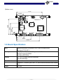
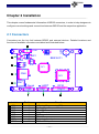
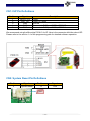
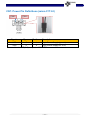
1
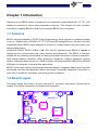
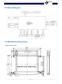
BE635 User Manual Rev. V1.0 © 2013-2014 Bolymin, Inc. All Rights Reserved. Copyright Copyright © 2013-2014 BOLYMIN, INC. All rights reserved. No part of the materials may be reproduced, copied or translated into any form by any means without prior written consent from BOLYMIN, INC. Disclaimer The contents of this document are subject to change without notice. Bolymin, Inc. reserves the right to make changes without further notice to any product herein to improve reliability, function or design. Bolymin, Inc. does not assume any liability arising out of the application or use of any product or circuit described herein; neither does it convey any license under its patent rights, nor the rights of others. Customers are advised to consult with Bolymin, Inc. or its commercial distributors before ordering. Getting Support Contact Information Company Address BOLYMIN, INC 5F, 38 Keya Road, Daya Dist., Central Taiwan Science Park, 42881 Taichung City, Taiwan, R.O.C. TEL +886-4-2565-8689 FAX +886-4-2565-8698 Web Site http://www.bolymin.com.tw Email [email protected] Service Hour 09:00 – 18:00 (UTC/GMT + 8) , Mon. to Fri. Revision History Version 1.0 Note Original Version Date 2014/03/17 Table of Content Chapter 1 Introduction ........................................................................................ 7 1.1 Features ............................................................................................................................ 7 1.2 Board Layout .................................................................................................................... 7 1.3 Block Diagram .................................................................................................................. 8 1.4 Mechanical Dimension ..................................................................................................... 8 1.5 Board Specification .......................................................................................................... 9 1.6 Ordering Information...................................................................................................... 10 1.7 Package Content ............................................................................................................ 11 1.8 Absolute Maximum Ratings ........................................................................................... 12 Chapter 2 Installation ........................................................................................ 13 2.1 Connectors ..................................................................................................................... 13 CN1: ISP Pin Definitions .............................................................................................................. 14 CN2: System Reset Pin Definitions ............................................................................................. 14 CN7: Power Pin Definitions (micro FIT 3.0) ................................................................................. 15 CN8: Dual RS232 Pin Definitions ................................................................................................ 16 CN8: One RS232 / One RS422 Pin Definitions............................................................................ 17 CN8: One RS232 / One RS485 Pin Definitions............................................................................ 18 CN9: SPI & IIC Pin Definitions ..................................................................................................... 19 CN10: GPIO / ADC Pin Definitions .............................................................................................. 20 CN11: Mini USB Pin Definitions ................................................................................................... 20 2.2 How to install USB driver ............................................................................................... 21 Chapter 3 Software Development Tool & Utility ............................................ 26 3.1 How to program the demo code .................................................................................... 27 3.2 Connecting the device ................................................................................................... 31 3.3 How to operate the demo program ............................................................................... 33 Running Hyper Terminal .............................................................................................................. 33 2nd UART Test ............................................................................................................................ 37 EEPROM Test ............................................................................................................................. 39 I2C Test ....................................................................................................................................... 40 SPI Test ....................................................................................................................................... 41 ADC Test ..................................................................................................................................... 42 GPIO Test .................................................................................................................................... 44 SD Card Test ............................................................................................................................... 46 Buzzer Test.................................................................................................................................. 48 Touch panel Draw Test ................................................................................................................ 49 LCD Test ..................................................................................................................................... 50 System Setting ............................................................................................................................ 51 Chapter 1 Introduction Welcome to use BE635 which is designed for an embedded control board with 3.5” TFT LCD display for customer to control other peripherals or devices. This chapter is to offer you basic information regarding BE635 to help you incorporate BE635 into your system. 1.1 Features BE635 is designed based on PIC32 32-bit microprocessor, which requires no operating system to run on. Together with a 320x240 3.5” TFT LCD and LED backlight built-in, this all-in-one LCD embedded system BE635 helps designer to enhance a compact design with cost, space, and design phase saving. Armed with RS232, RS422, RS485, USB, SPI, and I2C interface ports, BE635 is capable of interfacing and communicating with many devices and peripherals .The BE635 is therefore suitable for any industrial control panel for factory automation equipment, electronic instrument, HMI (human-machine interface), office automation equipment, medical equipment, parking system, ticketing system and so on. 512KB in-system self-programmable Flash offers sufficient ROM size for designers to develop their applications. BE635 is more than simply a Microchip development board: it integrates display and I/O so that developers may start her application without the hassle of hardware integration. Henceforth, a quick time to market for customers’ innovative product is ensured. 1.2 Board Layout This layout shows the location of each important IC, connector and jumper. Please refer to chapter 2 for further information on jumpers and connectors. SW1 CN5 CN2 UB1 CN1 SW2 BE635 D1 U7 U1 CN6 CN7 U3 Serial CN9 GPIO UART CN10 CN8 7 1.3 Block Diagram 1.4 Mechanical Dimension 8 54.67(VA ) 4-? 3.0 3.58 6 320*R G B *240 Dots 14.6 MAX 8.6 52.56(AA ) 70.08(AA ) 4.64 4.11 57.3 6 3.05 96.3 90.3 78.3 72.2(VA ) 4 67.3 65.3 (Front and side view) (Bottom view) 71.03 19.55 SW2 SW1 BE635 D1 U7 U1 8.64 CN6 22.48 36.71 49.58 CN5 CN2 UB1 CN1 CN7 U3 UART Serial CN9 CN8 GPIO CN10 21.5 40.3 63.67 1.5 Board Specification MCU High-performance, low-power PIC® 32-bit microprocessor Microchip PIC32 MCU Memory 512K Bytes In-System Self-Programmable Flash 64K Bytes Internal SRAM 16K Bytes EEPROM Display 3.5” TFT LCD with 320x240 resolution with LED backlight Touch Panel Supports four-wired resistive touch panel Serial Ports Supports 1 x RS232 port, and 1 x RS232/RS422/RS485/USB shared port Power DC 5.0V 9 1.6 Ordering Information Part No. (P/N) Resolution Voltage BE635BM1A1N 320 * 240 5V BE635BM1A2N 320 * 240 5V BE635BM1A3N 320 * 240 5V BE635BM1A4N 320 * 240 5V RS-232 RS-232 RS-422 RS-485 USB (UART) Note1. If you select USB interface version, you need to install the USB to RS232 driver. Please refer the section 2.2 to know how to install the driver. 10 1.7 Package Content Please check your package content upon receiving the product parcels. Besides the BE635 unit, make sure the following accessories (User selection) are included as well. NOTE: The term as "S/N Number" is the serial number of all accessories provided by Bolymin. S/N: OPBE657AM1E00 S/N: OPBE657AM1F00 S/N: OPBE657AM1G00 Cable 1: SPI, I2C (20cm) Cable 2: UART (50cm) Cable 3: GPIO, ADC (50cm) S/N: OPBE657AM1010 S/N: OPBE657AM1020 S/N: OPBE657AM1030 Micro SD 4GB Micro SD 8GB S/N: OPBE657AM1040 S/N: OPBE657AM100A S/N: OPBE657AM100B Microchip PICKIT 3 Program line Micro SD 32GB + Program line Note1. The Cable 1~3 is used for developed. Note2. The Micro SD 4GB is standard accessory. 11 Micro SD 16GB 1.8 Absolute Maximum Ratings Item Symbol Min Typ. Max Unit Operating Temperature TOP -20 - +70 ℃ Storage Temperature TST -30 - +80 ℃ Vdd-Vss - - 6.0 V Supply Voltage For BE635 12 Chapter 2 Installation This chapter covers fundamental information of BE635 connectors, in order to help designers to configure correct settings and connections between BE635 and the respective application. 2.1 Connectors Connectors are the key link between BE635 and external devices. Detailed locations and functions of available connectors are tabled and illustrated below. CN1 SW1 2 CN2 4 5 U1 CN6 CN7 U3 Serial CN9 6 Label 1:CN1 2:CN2 3:CN5 4:CN6 5:CN7 6:CN9 7:CN8 8:CN10 BE635 D1 U7 CN5 3 SW2 UB1 1 Pin No. 5 2 5 9 2 8 8 15 UART GPIO CN10 CN8 8 7 Function In-System Programming (ISP) System Reset Mini USB Connector Micro SD DC Power Jack SPI / I2C Series Interface Input GPIO / ADC Input 13 CN1: ISP Pin Definitions Pin No. 1 2 3 4 5 Signal /MCLR, VPP VDD_TGT GND PGD PGC Description Power Power on Target Ground Connects to PIC32 port PGD1, ICSPDAT Connects to PIC32 port PGC1, ICSPCLK We recommend using the Microchip PICKit 3 for ISP. Here is the connector definition about ISP. Please refer to the section 1.4 of the programming guide for detailed software operation. CN2: System Reset Pin Definitions Pin No 1 Signal System Reset Pin No. Signal VSS 2 PIN1 14 CN7: Power Pin Definitions (micro FIT 3.0) PIN2 PIN1 Signal Type Pin No. Description VSS P 1 Logic Power Supply (ground) VDD P 2 Logic Power Supply DC 5.0V, Mates with micro FIT (3.0) receptacle 43645-0200 15 CN8: Dual RS232 Pin Definitions Pin No Signal Pin No. Signal 1 VSS 5 NC 2 RS232 RX_1 6 RS232 RX_2 3 RS232 TX_1 7 RS232 TX_2 4 VSS 8 NC UART1 of BE635 offers one RS232 port (the voltage level is +/- 12V) for connection with a PC or other RS232 devices. RS232-1 RS232-2 Pin Definition of DB9 Connector: 5 9 5 9 1 6 1 6 16 CN8: One RS232 / One RS422 Pin Definitions Pin No Signal Pin No. Signal 1 VSS 5 RS422 TX+ 2 RS232 RX 6 RS422 TX- 3 RS232 TX 7 RS422 RX- 4 VSS 8 RS422 RX+ RS232 RS422 Pin Definition of DB9 Connector: 5 9 5 9 1 6 1 6 17 CN8: One RS232 / One RS485 Pin Definitions Pin No Signal Pin No. Signal 1 VSS 5 RS485 TXD+ 2 RS232 RX 6 RS485 TXD- 3 RS232 TX 7 NC 4 VSS 8 NC RS232 RS485 Pin Definition of DB9 Connector: 5 9 5 9 1 6 1 6 18 CN9: SPI & IIC Pin Definitions Pin No Signal Pin No. Signal 1 SDO 5 VSS 2 SS 6 SDA 3 SDI 7 SCL 4 CLK 8 VSS SPI IIC 19 CN10: GPIO / ADC Pin Definitions Pin No Signal Pin No. Signal 1 GPIO1 9 GPIO9 2 GPIO2 10 GPIO10 3 GPIO3 11 GPIO11 4 GPIO4 12 GPIO12 5 GPIO5 13 VSS 6 GPIO6 14 ADC IN 7 GPIO7 15 ADC VSS 8 GPIO8 GPIO: ( I/O Voltage 5.0V / 25mA max) ADC: (Voltage Range = 0~5V) CN11: Mini USB Pin Definitions Pin No Signal Pin No. Signal 1 VUSB 4 NC 2 D- 5 VSS 3 D+ 20 2.2 How to install USB driver The BE635 provides a stand-alone USB to RS232 serial converter (optional). If you select this interface, all what you need to do is to install the USB driver (please download USB driver from URL: http://www.bolymin.com.tw/dl/BE6XX_USB_driver.rar ) to your Windows System by referring to below instructions. Take Windows 7 for example, to install the USB driver on Windows 7 for the first time. Step 1: Connect BE635 device to your computer's USB port and power on the BE635. Mini USB connector, connect to PC Power Jack (DC 5V) Step 2: Right-click on Computer from your desktop or Windows Explorer, and select Device Manager. Locate and expand Other device, you can see the MCP2200 USB Serial Port Emulator. 21 Step 3: Right-click the device name (such as MCP220 USB Serial port Emulator) and select Update Driver Software. This will launch the Hardware Update Wizard. Step 4: Select “Browse my computer for driver software”. 22 Step 5: Click Browse and locate the USB driver folder (X64 for windows 64 bit system, x86 for windows 32 bit system) and click “OK” to next. Step 6: Click Install to install the driver. 23 Step 7: Installing driver software. Step 8: Now the USB driver installation for BE635 is completed. 24 Step 9: You can see the USB Serial Port at Ports (COM & LPT) of device Manager. The following example shows COM3 is available. 25 Chapter 3 Software Development Tool & Utility This chapter will show you how to setup and how to use the hyper terminal to operate the demo program on BE635. Following table lists the recommended software development tool and hardware connection of BE635. Item Description Software MPLAB Version 8.85 Development Tool Programmer PICkit3 Hardware Connection 26 3.1 How to program the demo code Step 1: Connect PICkit 3 programmer to the connector CN1 and provide the power to BE635, which is indicated in below image. CN1 ISP Connector PICkit 3 Power Jack Connect to PC Step 2: Start MPLAB IDE by clicking either on the Desktop or Start menu item, how to install the MPLAB IDE, please refer to the BE635 programming guide section 1.2 Software Development Tool Installation. Step 3: Inside MPLAB IDE, click in the menu bar on File Import and load the hex file into MPLAB IDE. 27 Step 4: Import Hex file. Step 5: Select Programmer: Inside MPLAB IDE, please select the correct programmer according to your configuration. In the menu bar, please click on Programmer Select Programmer PICkit3. 28 Step 6: Power target circuit from PICkit3, check Programmer Setting Power and place a checkmark at “Power target from PICkit3”. Step 7: The programmer is connected to MPLAB IDE successfully, when it shows the Device ID Revision in MPLAB IDE. 29 Step 8: To upload the hex file to your target, please click “Program” icon to upload the hex file to BE635. Click on “Program” 30 3.2 Connecting the device Below image illustrates how to connect BE635. Micro SD Card slot Power connector I2C and SPI connector Serial Port connector st nd (1 UART, 2 UART ) GPIO connector Step 1: Connect the test board connectors (GPIO, Serial port, I2C & SPI connector ) if you want to test or use these functions. Step 2: Connect the test board with the cable configuration as shown below. Connect the test board to +5V DC GPIO cable I2C/SPI cable +5V DC Power supply Test board 31 Step 3: To control the device in terminal mode or send / receive data using the 2nd UART, please connect the serial port (1st UART, 2nd UART) cable. The 1st UART serial cable with 3 wires controls the device using a terminal emulator such as HyperTerminal. In order to send and receive data via the RS232/RS422/RS485/USB, connect 2nd UART according to below image (cable with 5 wires). 3 wires 1st UART HyperTerminal connection 5 wires 2nd UART Auxiliary connection Step 4: Next, decompress files (BE635_DTP_XXXXXXXX_vXXX.rar ) that Bolymin provides and copies the content of demo_pic folder to the micro SD card’s main folder and insert the card into BE635. Demo picture 32 3.3 How to operate the demo program BE635 supports touch panel. Bolymin will calibrate the touch panel before shipping out. User can click the screen of BE635 to operate the demo program, if touch panel couldn’t work, you can use hyper terminal for terminal emulation and recalibration. The PC keyboard can emulate as an input device to BE635. Here is the step-by-step guide. Running Hyper Terminal Step 1: Make sure you have at least one RS-232 serial port available. The following example shows COM3 is available. Step 2: On Windows XP PC: Start All programs Accessories Communication HyperTerminal (or Windows key +R, enter “ hypertrm ”) 33 Step 3: Click No if you do not use hyper terminal to telnet to default host. Step 4: Enter the file name to store the hyper terminal settings. System will auto add a .ht extension name. Please define a name and choose a icon for this connection, and click Ok to continue. Step 5: Select COM port as appropriate. Hyper terminal will pull down only valid COM ports. Choose a suitable COM port, and click Ok to continue. 34 Step 6: It is required to set the serial communication as follows – 115200 bps, / 8/ None/ 1/ None Key in COM port setting: 115200/ 8/ No/ 1/ No, and click ok to continue. Step 7: Now you plug in the power connector into the unit. The main screen on the device lets you choose the operations. Available operations are showed in Hyper Terminal Screen as depicted below. On your keyboard, hit the respective number to execute the operation. (Hyper Terminal Screen) (BE635 Screen) 35 Name Description 2nd UART Test of 2nd UART sending/receiving functionality at different baud rates EEPROM Test of EEPROM reading/writing functionality I2C I2C EEPROM; test of EEPROM reading/writing functionality SPI SPI FLASH; test of FLASH reading/writing functionality ADC Oscilloscope display of ADC values versus time GPIO General purpose I/O testing. Setting output pins, reading input pins SD Card Create File/Read/Write/Delete functionality testing Buzzer Application example: Piano TP Draw Application example: Touchpad drawing program LCD Screen filling examples, displaying images examples System Backlight Intensity setting, product information, T/P calibration 36 2nd UART Test This screen lets you test the 2nd UART functionality Return to main screen Sending Bytes 0x55, 0xAA, 0x00, 0xFF and letters & symbols Baud rate settings Switch from ASCII to hexadecimal display Step 1: First, connect the 2nd UART to your PC in the same way as you connected the 1st UART as described in section 3.2 connecting the device. Step 2: Set a baud rate in HyperTerminal. On BE635, set the same baud rate in the GUI. Available baud rates are 9600, 19200, 38400, 57600, 115200 . Step 3: On BE635, tap on one of the send buttons (0x55, 0xAA, 0x 00, 0xFF, ABC) to send the characters to the 2nd UART’s Hyper Terminal. For example that to send the characters with internal fonts from 1st UART, the Hyper Terminal of 2nd UART will show the characters with internal fonts. 2nd UART 1st UART 37 Step 4: Type in the 2nd UART’s HyperTerminal “Hello World”. The sent string now shows in the receive area on the device. Step 5: Once the receive area is full, you can delete the contents with the broom Step 6: In Terminal mode, the screen shows as depicted below. Please hit the respective number to execute the operation on your keyboard,. 38 EEPROM Test This screen lets you test the EEPROM’s functionality Writing values Address LO/HI page Previous memory page Next memory page Back to main screen Step 1: Select a memory page you would like to see by using the Step 2: With the LO/HI page button buttons. , address are switched to current address + 8 and back. Step 3: Select a value (0x55, 0xAA, 0x 00, 0xFF) with which you would like to fill the current memory page (fills low and high page). Step 4: In Terminal mode, the screen shows as depicted below, on your keyboard, please hit the respective number to execute the operation. 39 I2C Test This screen lets you test the I2C EEPROM’s functionality1. Please make sure the test board is connected to BE635 and 5V power supply is connected to the test board. Writing values Address LO/HI page Back to main screen Step 1: Select a value with which you would like to fill the current memory high and low memory page: 0x55, 0xAA, 0x 00 or 0xFF. Step 2: With the LO/HI page button , address are switched to current address + 8 and back. Step 3: In Terminal mode, the screen shows as depicted below, on your keyboard, please hit the respective number to execute the operation. 1 The I2C EEPROM is an application example by Bolymin. Any kind of I2C device can be connected to BE635 40 SPI Test This screen lets you test the SPI FLASH’s functionality2. Please make sure the test board is connected to BE635 and a 5V power supply is connected to the test board. Writing values Address LO/HI page Back to main screen Step 1: Select a value with which you would like to fill the current memory high and low memory page: 0x55, 0xAA, 0x00 or 0xFF. Step 2: With the LO/HI page button , address are switched to current address + 8 and back. Step 3: In Terminal mode, the screen shows as depicted below, on your keyboard, please hit the respective number to execute the operation. 2 The SPI FLASH is an application example by Bolymin. Any kind of SPI device can be connected to BE635 41 ADC Test This screen lets you test the ADC’s functionality. Please make sure the test board is connected to BE635 and a 5V power supply is connected to the test board. ADC values vs. time Back to main screen Current ADC value Step 1: Vary the potentiometer on the test board and observe the values being drawn on the screen. 42 Step 2: In Terminal mode, the screen shows as depicted below, on your keyboard, please hit 0 to exit the test. 43 GPIO Test This screen lets you test the general purpose I/O functionality, please make sure the test board is connected to BE635 and a 5V power supply is connected to the test board. Status of input pins Input High : Green Input Low : Red Status of output pins Output High: Green Output Low : Red Back to main screen Step 1: The GUI lets you see the state of the GPIO pins. In the demo test program, GPIO_1 ~ GPIO_6 are set as input pins and GPIO_7 ~ GPIO_12 are output pins. Whenever the value of the input pins change, the value of related output pins will change accordingly. Here is the mapping table of demo test program. You can change the I/O mode of each pin in your program. Detailed information about GPIO control can be found in section 2.8 of the programming guide. Input pin GPIO_1 GPIO_2 GPIO_3 GPIO_4 GPIO_5 GPIO_6 Output pin GPIO_7 GPIO_8 GPIO_9 GPIO_10 GPIO_11 GPIO_12 For above setting of the output pins (8, 9, 11, 12 high level), the results can be seen in the image below. 44 Step 2: In Terminal mode, this screen shows as depicted below. On your keyboard, please hit 1-6 to toggle the state of the output pins. In the MODE line, the mode of the GPIO pins are shown with GPIO pin 1 on the left and pin12 on the right (I=Input, O=Output). The VALUE line displays the state of the pin. Press 0 to return to the main screen. 45 SD Card Test This screen lets you test the SD Card’s read/write/delete functionality. Create new file Read file File contents Write to file Delete file Back to main screen Step 1: From the operations on the right hand side, choose “Create”, “Read”, “Write” or “Delete”. The contents of the file on the device are shown in the contents area. ICON Description Create new txt file on SD card Read txt file contents of SD card and display on BE635 Write the string to txt file on SD card Delete the txt file of SD Card Step 2: The different operations performed on the device will show the results as depicted in below images. Create Write 46 Delete Step 3: In Terminal mode, the screen shows as depicted below. Step 4: On your keyboard, please hit the respective number to execute the operation. Create Read 47 Delete Buzzer Test This screen lets you test the Buzzer functionality. Back to main screen Step 1: Hit the black or white keys on the piano. The respective note will be played through the buzzer. Step 2: In Terminal mode, the screen shows as depicted below, on your keyboard, please hit the respective number to play a certain tone. Press 0 to return to the main screen. 48 Touch panel Draw Test This screen lets you test the touchpad functionality using a simple drawing program. Back to main screen Step 1: Write text or hit certain coordinates and check in the terminal window, if the coordinates is not match the coordinates of the touched point. A calibration might be necessary before using the drawing program. 49 LCD Test This screen lets you test the image and built in font functionalities. (Hyper Terminal Screen) (BE635 Screen) Step 1: Operations that can be performed are filling the screen with red, green, blue, white, and black as well as showing images and fonts. Picture A Picture B Font 50 Picture C System Setting This screen lets you set the system’s backlight intensity, display the product information and calibrate the touch panel. (Hyper Terminal Screen) (BE635 Screen) ICON Description The backlight can be adjusted from 10% to 100% in steps. The product information displays the product information stored in memory. Calibration is performed by using 5-points calibration where each of the 5 points is being touched successively. Backlight Product info. 51 Calibration In terminal mode, the screens show as depicted below. Backlight Product info. 52 Calibration < End of BE635 User Manual > 53