1
MOST150 Repeater
User’s Manual
UM_MOST150_Repeater_V01_00_XX-1.pdf
Mar. 2010
®
MOST
Media Oriented Systems Transport
Multimedia and Control
Networking Technology
Copyright © 2010 SMSC
MOST150 Repeater
Legend
Copyright © 2010 SMSC. All rights reserved.
Please make sure that all information within a document marked as 'Confidential' or 'Restricted Access' is handled
solely in accordance with the agreement pursuant to which it is provided, and is not reproduced or disclosed to others
without the prior written consent of SMSC. The confidential ranking of a document can be found in the footer of every
page. This document supersedes and replaces all information previously supplied. The technical information in this
document loses its validity with the next edition. Although the information is believed to be accurate, no responsibility is
assumed for inaccuracies. Specifications and other documents mentioned in this document are subject to change without notice. SMSC reserves the right to make changes to this document and to the products at any time without notice.
Neither the provision of this information nor the sale of the described products conveys any licenses under any patent
rights or other intellectual property rights of SMSC or others. There are a number of patents and patents pending on
the MOST technology and other technologies. No rights under these patents are conveyed without any specific agreement between the users and the patent owners. The products may contain design defects or errors known as anomalies, including but not necessarily limited to any which may be identified in this document, which may cause the product
to deviate from published descriptions. Anomalies are described in errata sheets available upon request. SMSC products are not designed, intended, authorized or warranted for use in any life support or other application where product
failure could cause or contribute to personal injury or severe property damage. Any and all such uses without prior written approval of an officer of SMSC will be fully at your own risk. MediaLB, SMSC and MOST are registered trademarks
of Standard Microsystems Corporation ("SMSC") or its subsidiaries. Other names mentioned may be trademarks of
their respective holders.
SMSC disclaims and excludes any and all warranties, including without limitation any and all implied warranties of merchantability, fitness for a particular purpose, title, and against infringement and the like, and any and all warranties arising from any course of dealing or usage of trade. In no event shall SMSC be liable for any direct, incidental, indirect,
special, punitive, or consequential damages; or for lost data, profits, savings or revenues of any kind; regardless of the
form of action, whether based on contract; tort; negligence of SMSC or others; strict liability; breach of warranty; or otherwise; whether or not any remedy of buyer is held to have failed of its essential purpose, and whether or not SMSC
has been advised of the possibility of such damages.
User’s Manual
Page 2
Copyright © 2010 SMSC
UM_MOST150_Repeater_V01_00_XX-1.pdf
MOST150 Repeater
MOST150 Repeater
User’s Manual
Copyright © 2010 SMSC
UM_MOST150_Repeater_V01_00_XX-1.pdf
Page 3
MOST150 Repeater
User’s Manual Versions
Doc. Number
UM_MOST150_Repeater_V01_00_XX-1.pdf
User’s Manual
Page 4
Date
Mar. 2010
Copyright © 2010 SMSC
Description
First version
UM_MOST150_Repeater_V01_00_XX-1.pdf
MOST150 Repeater
TABLE OF CONTENTS
1 PREFACE .................................................................................................................... 9
1.1 Intended Use .................................................................................................................................... 9
1.2 Scope of Delivery ............................................................................................................................. 9
2 INTRODUCTION ....................................................................................................... 10
2.1 Feature List .................................................................................................................................... 11
2.2 Block Diagram ................................................................................................................................ 11
2.3 Functional Description .................................................................................................................... 12
2.4 Description of Start-up and Shut-down in Detail ............................................................................ 13
2.4.1 Light on in the Main Ring ....................................................................................................... 13
2.4.2 Light off in the Extension Ring ............................................................................................... 15
2.4.3 Light off in the Main Ring ....................................................................................................... 17
2.4.4 Slave Wake-up in the Extension Ring .................................................................................... 18
2.5 Typical Applications ........................................................................................................................ 20
2.5.1 Network Extension ................................................................................................................. 20
2.5.2 Single Signal Recovery .......................................................................................................... 20
2.5.3 Device Replacement .............................................................................................................. 21
2.5.3.1 Usage in a Garage ......................................................................................................... 21
2.5.4 Connecting OptoLyzer G2 3150o ...........................................................................................22
3 SWITCHES AND CONNECTORS ............................................................................. 23
3.1 Power Connector ............................................................................................................................ 23
3.1.1 Power Supply ......................................................................................................................... 23
3.2 Relay Contact ................................................................................................................................. 23
3.2.1 Relay Plug Connector ............................................................................................................ 23
3.3 MOST Interface ............................................................................................................................. 23
3.4 LED ................................................................................................................................................ 24
4 TECHNICAL SPECIFICATION ................................................................................. 25
4.1 Mechanical and Environmental Characteristics ............................................................................. 25
4.2 Electrical Characteristics ................................................................................................................ 25
User’s Manual
Copyright © 2010 SMSC
UM_MOST150_Repeater_V01_00_XX-1.pdf
Page 5
MOST150 Repeater
LIST OF FIGURES
Figure 2-1:
Figure 2-2:
Figure 2-3:
Figure 2-4:
Figure 2-5:
Figure 2-6:
Figure 2-7:
Figure 2-8:
Figure 2-9:
Figure 2-10:
Figure 2-11:
Figure 2-12:
Figure 2-13:
Figure 2-14:
Figure 2-15:
Figure 2-16:
Figure 3-1:
User’s Manual
Page 6
Block Diagram ....................................................................................................................... 11
Light in Main Ring Step 1....................................................................................................... 13
Light in Main Ring Step 2....................................................................................................... 13
Light in Main Ring Step 3....................................................................................................... 14
Light off in Extension Ring Step 1.......................................................................................... 15
Light off in Extension Ring Step 2.......................................................................................... 15
Light off in Extension Ring Step 3.......................................................................................... 16
Light off in Main Ring Step 1.................................................................................................. 17
Light off in Main Ring Step 2.................................................................................................. 17
Slave Wake-up Step 1 ...........................................................................................................18
Slave Wake-up Step 2 ...........................................................................................................18
Slave Wake-up Step 3 ...........................................................................................................19
MOST150 Repeater with Extension Ring .............................................................................. 20
Signal Recovery in the MOST150 Repeater.......................................................................... 20
Device Replacement by MOST150 Repeater........................................................................ 21
MOST150 Repeater with Connected OptoLyzer G2 3150o .................................................. 22
Power Connector - Rear Panel View ..................................................................................... 23
Copyright © 2010 SMSC
UM_MOST150_Repeater_V01_00_XX-1.pdf
MOST150 Repeater
LIST OF TABLES
Table 3-1:
Table 4-1:
Table 4-2:
User’s Manual
LEDs ...................................................................................................................................... 24
Mechanical Dimensions of the MOST150 Repeater.............................................................. 25
Electrical Characteristics ....................................................................................................... 25
Copyright © 2010 SMSC
UM_MOST150_Repeater_V01_00_XX-1.pdf
Page 7
MOST150 Repeater
User’s Manual
Page 8
Copyright © 2010 SMSC
UM_MOST150_Repeater_V01_00_XX-1.pdf
MOST150 Repeater
1 Preface
1.1 Intended Use
This SMSC product is intended to be used for developing, testing, or analyzing MOST based multimedia
products and systems by persons with experience in developing multimedia devices.
Do not interfere in the product's original state, otherwise user safety, faultless operation and electromagnetic compatibility is not guaranteed.
1.2 Scope of Delivery
This product is delivered with:
•
•
•
•
MOST150 Repeater box
Optical fibers
Power cable set
Plug connector fitting for the relay contact
Check your shipment for completeness. If you have any complaints direct them to [email protected] (Europe and Asia) or to [email protected] (America). Providing the delivery
note number eases the handling.
User’s Manual
Copyright © 2010 SMSC
UM_MOST150_Repeater_V01_00_XX-1.pdf
Page 9
MOST150 Repeater
2 Introduction
When examining MOST150 network environments, connecting to the network without changing the network's structure is an important requirement. The MOST150 Repeater is a versatile device that can act as
a network extender or provide monitor out functionality1 without interfering in the network’s structure. It can
help managing many of the tasks arising during the development phase of a MOST150 system.
This starts with single signal recovery or device replacement for an defective device and continues with
including of additional MOST150 devices in a MOST network when used as an extender. The transmit signal of the MOST150 Repeater’s extension side can be connected to a analyzing device, such as an OptoLyzer® G2 3150o, to spy MOST150 network traffic without changing the number of active network nodes.
After the MOST150 Repeater has detected light, it is switched on immediately. It also supports slave wakeup on the extension side. Additionally, the MOST150 Repeater has a switch off mechanism, which is activated when detecting no light for a dedicated time.
The MOST150 Repeater provides a relay contact whose position depends on whether light is detected or
not. Thus the MOST150 Repeater is able to loop an external provided power signal through the closed relay
contact.
For easy lock indication, the MOST150 Repeater provides respectively one status LED on the main and
the extension side.
Power will be applied via a screwable 3-pole power plug and a cable pigtail. The power supply follows the
automotive requirements (filtering, load dump protection, etc.). If there is no activity on the bus, the
MOST150 Repeater falls into a stand-by mode, where the overall current consumption is less then 30 µA.
Therefore no other cables are required than UBATT (battery power) and GND (ground).
Important: The number of nodes is not affected by using the MOST150 Repeater since
there is no active node inside. It lasts 300 ms till an extension ring is included in the MOST
network after it is connected to the MOST150 Repeater.
1. This means the TX of the extension ring is only connected with the RX of an analyzing device
(spy, e.g., the OptoLyzer OL3150o) to avoid data / message loss that may occur otherwise until the
extension ring will be included (typically 300 ms).
User’s Manual
Page 10
Copyright © 2010 SMSC
UM_MOST150_Repeater_V01_00_XX-1.pdf
MOST150 Repeater
2.1 Feature List
The MOST150 Repeater features the following:
•
•
•
•
•
•
•
•
Two MOST150 oPHY (optical Physical) layer compliant interfaces at main and extension side
Internal automotive compliant power supply
Low power consumption in sleep mode (< 30 µA)
Slave wake-up possible at extension side
Monitor-out functionality without extra FOT on extension side
Indication of the lock status through a LED on each side
Relay-switched lock contact max, 20 V / 1 A, short-circuit protected
Signal recovery
2.2 Block Diagram
Figure 2-1: Block Diagram
User’s Manual
Copyright © 2010 SMSC
UM_MOST150_Repeater_V01_00_XX-1.pdf
Page 11
MOST150 Repeater
2.3 Functional Description
The MOST150 Repeater has two interfaces that act slightly different: The main ring to be connected to the
timing master and the extension ring.
After powering, the MOST150 Repeater switches into stand-by mode having a low power consumption
less than 30 µA. Both Lock LEDs remain dark. As soon as the MOST150 Repeater detects light on an
interface the corresponding LED lights red but switches immediately to green if the interface detects also
lock. The LED of the other interface remains dark.
If the interface on the main ring detects light the MOST network is closed by default. If the interface of the
extension ring detects stable lock it takes up to 300 ms until the extension ring is included in the MOST
network. If the extension is deconnected it takes about 10 ms to close the main ring.
The MOST150 Repeater also supports slave wake-up. This means, the extension ring is able to wake-up
the main ring being in sleep mode (power consumption less than 30 µA) after stable lock has been
detected on the extension’s side.
In case the MOST150 Repeater detects no light it switches back to sleep mode after 2000 ms.
The MOST150 Repeater provides a relay contact allowing to loop an external provided power signal
through the closed relay contact. The relay contact, which is short circuit protected, closes if light is
detected either on the main ring or on the extension ring side. The power signal can be used for powering
an external device e.g., for data logging or storage. Thus it is possible to log all data of the MOST network.
If the power signal exceeds the maximum values for current (1 A) the relay drops out. Before the relay contact can be reused the MOST Repeater has to be switched off and on again.
User’s Manual
Page 12
Copyright © 2010 SMSC
UM_MOST150_Repeater_V01_00_XX-1.pdf
MOST150 Repeater
2.4 Description of Start-up and Shut-down in Detail
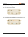
2.4.1 Light on in the Main Ring
When the MOST150 Repeater obtains no light on RX it remains in sleep mode (indicated as grey dashed
lines in Figure 2-2) assuming the device itself is powered .
Figure 2-2: Light in Main Ring Step 1
If light is detected on RX in the main ring the MOST150 Repeater switches on. The light is transmitted
back to TX on the main ring, i.e., via an internal loop, and to the TX of the extension ring (indicated by the
orange lines in Figure 2-3). In additon, the MOST signal will be recovered via an internal PLL.
Figure 2-3: Light in Main Ring Step 2
User’s Manual
Copyright © 2010 SMSC
UM_MOST150_Repeater_V01_00_XX-1.pdf
Page 13
MOST150 Repeater
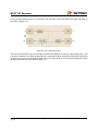
In case a proper MOST device is connected in the extension ring its RX obtains also light (indicated by
blue lines in Figure 2-3).
Figure 2-4: Light in Main Ring Step 3
If the RX of the extension ring receives light the MOST150 Repeater checks the signal quality (lock) and
includes the extension ring within at least 300 ms in the MOST network (indicated by the green dashed line
of influence in Figure 2-4). Internally a switch opens the loop behind the main ring and includes the external ring (indicated by the blue lines in Figure 2-4).
User’s Manual
Page 14
Copyright © 2010 SMSC
UM_MOST150_Repeater_V01_00_XX-1.pdf
MOST150 Repeater
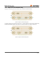
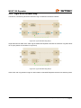
2.4.2 Light off in the Extension Ring
The base is a closed ring where the extension ring is included in the MOST network.
Figure 2-5: Light off in Extension Ring Step 1
If a break is detected on the extension ring’s side i.e., no light is detected on the RX of the extension ring,
the MOST150 Repeater keeps the ring closed for 10 ms (see position of the switch in Figure 2-6).
Figure 2-6: Light off in Extension Ring Step 2
User’s Manual
Copyright © 2010 SMSC
UM_MOST150_Repeater_V01_00_XX-1.pdf
Page 15
MOST150 Repeater
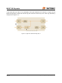
If the break lasts more than 10 ms (indicated by the green dashed line of influence in Figure 2-6) the
MOST150 Repeater excludes the external ring and closes the internal loop of the main ring (indicated by
orange lines in Figure 2-7).
Figure 2-7: Light off in Extension Ring Step 3
User’s Manual
Page 16
Copyright © 2010 SMSC
UM_MOST150_Repeater_V01_00_XX-1.pdf
MOST150 Repeater
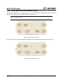
2.4.3 Light off in the Main Ring
The base is a closed ring where the extension ring is included in the MOST network.
Figure 2-8: Light off in Main Ring Step 1
If light switches off at RX of the main ring the MOST150 Repeater excludes the extension ring after about
10 ms (see position of the switch in Figure 2-8).
Figure 2-9: Light off in Main Ring Step 2
If RX of the main ring obtains no light for about 2000 ms the MOST Repeater switches into stand-by mode.
User’s Manual
Copyright © 2010 SMSC
UM_MOST150_Repeater_V01_00_XX-1.pdf
Page 17
MOST150 Repeater
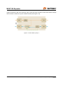
2.4.4 Slave Wake-up in the Extension Ring
The MOST150 Repeater is in stand-by mode i.e., the device itself is powerd but RX of the main ring
obtains no light (indicated by grey dashed lines in Figure 2-10).
Important: After a slave wake-up it lasts 300 ms till the extension ring is included and visible in the MOST network.
Figure 2-10: Slave Wake-up Step 1
RX on the extension ring detects light transmitted by the slave (indicated by blue lines in Figure 2-11).
Figure 2-11: Slave Wake-up Step 2
User’s Manual
Page 18
Copyright © 2010 SMSC
UM_MOST150_Repeater_V01_00_XX-1.pdf
MOST150 Repeater
If light is detected on RX of the extension ring for about 300 ms the positon of the internal switch changes
and includes the extension ring to the MOST network (see Figure 2-12).
Figure 2-12: Slave Wake-up Step 3
User’s Manual
Copyright © 2010 SMSC
UM_MOST150_Repeater_V01_00_XX-1.pdf
Page 19
MOST150 Repeater
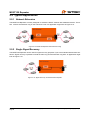
2.5 Typical Applications
2.5.1 Network Extension
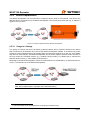
The MOST150 Repeater is mainly designed to extend the MOST network with additional devices. Therefore connect the extension ring on the extension’s side. An application might look as Figure 2-13.
Figure 2-13: MOST150 Repeater with Extension Ring
2.5.2 Single Signal Recovery
The MOST150 Repeater can be used for signal recovery purposes if you have extended transmission distances. Signal recovery is possible on both the main ring and the extension ring side. An application might
look as Figure 2-13.
Figure 2-14: Signal Recovery in the MOST150 Repeater
User’s Manual
Page 20
Copyright © 2010 SMSC
UM_MOST150_Repeater_V01_00_XX-1.pdf
MOST150 Repeater
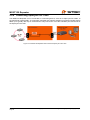
2.5.3 Device Replacement
The MOST150 Repeater can be used when a defective device needs to be replaced. Just remove the
defective device and replace it by the MOST150 Repeater. The internal loop closes the ring. In addition a
signal recovery is done.
Figure 2-15: Device Replacement by MOST150 Repeater
2.5.3.1 Usage in a Garage
In a garage a common use case is to identify a defective MOST device. Therefor disconnect the device
that is assumed to be defective and connect the MOST150 Repeater instead. If the MOST ring works
properly the removed MOST device is probably faulty and should be replaced by a new one. If the MOST
ring does not work properly1 the MOST150 Repeater can be used to replace one device after the other in
the ring except the controlling devices (e.g., headunit, timing master). For details how to evaluate the
defective device refer e.g., to the OEM’s work instruction.
Replacing by the MOST150 Repeater means the replaced device is substituted by an electrical short-circuit (i.e., the internal loop of the MOST150 Repeater).
Note: The extension functionality of the MOST150 Repeater is not considered in the use
case ’device replacement in a garage’ that is described above.
1.The functionality of the replaced device is missing in the MOST ring.
User’s Manual
Copyright © 2010 SMSC
UM_MOST150_Repeater_V01_00_XX-1.pdf
Page 21
MOST150 Repeater
2.5.4 Connecting OptoLyzer G2 3150o
The MOST150 Repeater can be connected to a monitoring device, such as an OptoLyzer G2 3150o, to
spy MOST150 network traffic. To avoid data / message loss until the extension ring will be included (which
takes up to typically 300 ms) we recommend to only connect the TX of the extension port with the RX of
the OptoLyzer OL3150o.
Figure 2-16: MOST150 Repeater with Connected OptoLyzer G2 3150o
User’s Manual
Page 22
Copyright © 2010 SMSC
UM_MOST150_Repeater_V01_00_XX-1.pdf
MOST150 Repeater
3 Switches and Connectors
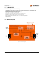
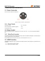
3.1 Power Connector
Power connector: Binder 09-3403-00-03
Figure 3-1: Power Connector - Rear Panel View
3.1.1 Power Supply
Operating Voltage:
8 V - 30 V (DC)
Power Consumption: Operation (typical):
6W
Current Drain (max):
0.5 A
3.2 Relay Contact
Relay-switched lock contact: Phoenix MC 1.5/ 2-G-3.81, max. 20 V / 1 A, short-circuit protected against
6 A.
3.2.1 Relay Plug Connector
The delivered connector can be plugged in the relay contact of the MOST150 Repeater. An external device
can be connected via the screw connection.
MINI COMBICON Connector MC1,5/2-ST-3,81, to be used with max. 20 V / 1 A.
3.3 MOST Interface
The MOST150 Repeater can be connected to the MOST network on both interfaces via a MOST150 2+0
connector.
• Tx: Optical output for MOST network
• Rx: Optical input for MOST network
User’s Manual
Copyright © 2010 SMSC
UM_MOST150_Repeater_V01_00_XX-1.pdf
Page 23
MOST150 Repeater
3.4 LED
There is one status LED on each interface. The color of the LED and its meaning is described in the table
below.
LED Color
Interface
Main Ring
Off
Extension Ring
Red
Green
Main Ring /
Extension Ring
Main Ring /
Extension Ring
Duration
Description
Describes two states:
The MOST150 Repeater is not powered.
The MOST Repeater is powered but in sleep mode as there is no light
detected on RX.
Describes two states:
The MOST150 Repeater is not powered.
The main ring is closed but receives no light at RXof the extension ring.
Visible
The interface detects light but no stable lock.
continuously
The interface detects a stable lock.
Table 3-1: LEDs
User’s Manual
Page 24
Copyright © 2010 SMSC
UM_MOST150_Repeater_V01_00_XX-1.pdf
MOST150 Repeater
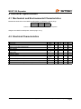
4 Technical Specification
4.1 Mechanical and Environmental Characteristics
Mechanical dimensions of the MOST150 Repeater in millimeters, without plugs:
Height
36
Width
85
Depth
121
Table 4-1: Mechanical Dimensions of the MOST150 Repeater
Weight of the MOST150 Repeater, without plugs: 210 g.
4.2 Electrical Characteristics
Parameter
Input Power
Current Consumption (Active Mode)
Symbol
UBatt
IActive
Current Consumption (Sleep Mode)
ISleep
Min
8
Typ
12
Max
30
Unit
V
300
500
mA
30
50
µA
Relay Contact
Load Voltage
ULd
20
V
Load Current
ILd
1
A
Switching Times
Time to Sleep Mode after Light Off
TSleep
Time from Sleep Mode to Active Mode
TActive
8
ms
Time till Stable Lock if Extension Is Included to Main Ring
TLkIn
300
ms
Time to Close the Main Ring after Excluding the Extension
TClEx
10
ms
2000
ms
Table 4-2: Electrical Characteristics
User’s Manual
Copyright © 2010 SMSC
UM_MOST150_Repeater_V01_00_XX-1.pdf
Page 25
MOST150 Repeater
Notes:
User’s Manual
Page 26
Copyright © 2010 SMSC
UM_MOST150_Repeater_V01_00_XX-1.pdf
MOST150 Repeater
Notes:
User’s Manual
Copyright © 2010 SMSC
UM_MOST150_Repeater_V01_00_XX-1.pdf
Page 27
Further Information
For more information on SMSC’s automotive products, including integrated circuits, software, and MOST
development tools and modules, visit our web site: http://www.smsc-ais.com. Direct contact information is
available at: http://www.smsc-ais.com/offices.
SMSC Europe GmbH
Bannwaldallee 48
76185 Karlsruhe
GERMANY
SMSC
80 Arkay Drive
Hauppauge, New York 11788
USA
Technical Support
Contact information for technical support is available at: http://www.smsc-ais.com/contact.