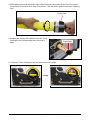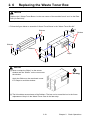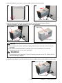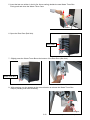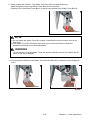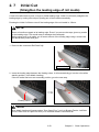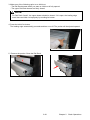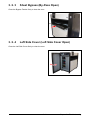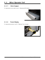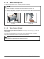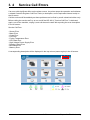
1
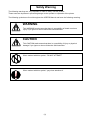
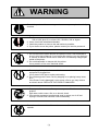
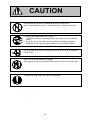
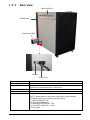
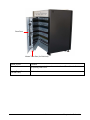
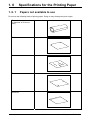
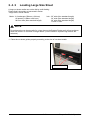
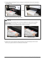
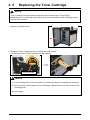
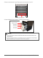
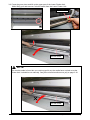
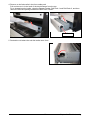
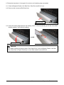
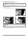
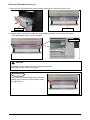
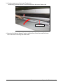
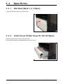
KIP 940 User Manual
Version A.
Thank you for purchasing the DIGITAL COLOR PRINTER KIP 940.
This Hardware Operation Guide contains functional and operational explanations for the KIP 940.
Please read this Hardware Operation Guide carefully before using the Printer.
Please keep this Hardware Operation Guide for future reference.
When this machine is installed in U.S.A.
This equipment satisfies the requirements in Part 15 of FCC Rules for a Class A computing device.
Operation is subject to the following two conditions:
(1) This device may not cause harmful interference.
(2) This device must accept any interference received, including interference that may cause
undesired operation.
When this machine is installed in Europe
This equipment satisfies the requirements in CISPR 22 for a Classic A computing device.
Operation of this equipment in a residential area may cause unacceptable interference to radio and TV
reception requiring the operator to take whatever steps are necessary to correct the interference.
Do not install this machine around electronic equipment or precision instruments.
Other devices may be affected by electrical noise during operation.
If Machine is installed near other electronic equipment, such as a TV or a radio, interference
to said equipment, such as noise or flickering, may occur.
Use a separate power line and install the PRINTER as far as possible from said equipment.
The symbol shown indicates that this product conforms to Directive
2012/19/EU of the European Parliament and the council of 4 July
2012 on waste electrical and electronic equipment (WEEE) and does not
apply to countries outside of EU.
(1)
Safety Warning
The following warnings are very important in order to safely use this product.
These notes are important in preventing danger to the operator or operation of the printer.
The following symbols are found throughout the USER’S Manual and have the following meaning:
WARNING
This WARNING mark means that there is a possibility of death or serious
injury if you ignore or do not follow the said instruction.
CAUTION
This CAUTION mark means that there is a possibility of injury or physical
damage if you ignore or do not follow the said instruction.
When marked with this symbol, “DO NOT ATTEMPT”
When marked with this symbol, “pay close attention to”
(2)
WARNING
Ground the product with a correct ground source or you may be electrically
shocked.
1. The Power source should be as follows:
220 to 240V plus 6% or minus 10%, 50/60Hz, 20A or higher
2. Use a circuit with a dedicated breaker.
3. Install the product as close to the wall outlet as possible.
4. If you wish to move the printer, please contact your service personnel.
1. Do not remove the screw and do not open the cover if not instructed to
do so in this User’s Manual. If you ignore this warning, you may be burnt
or receive an electric shock due to a hot item or electrically charged part
inside of the printer.
2. Do not disassemble or tamper with the printer.
It may result in a fire or an electrical shock.
1. Do not plug in the printer into a multi-wire connector in which some other
equipment is plugged into.
It may cause a fire due to outlet overheating.
2. Do not damage the Power Cord by stepping on or placing heavy items
on it.
If the Power Cord is damaged, it may cause a fire or you may receive
an electric shock. REPLACE THE CORD IF DAMAGED!
1. Do not put a flower vase, a flowerpot or any water-filled item on the
product.
Spilt water could cause a fire or an electric shock.
2. If the product generates an abnormal smell or noise, turn it off and
unplug it from the wall electrical outlet immediately.
Do not throw the toner into a fire or other sources of heat, as it can
explode.
(3)
CAUTION
Do not install the printer in a humidified room or a dusty room.
Also, do not install the printer on an unstable floor as injuries may occur.
1. Unplug the printer before you move it.
The power cord may be damaged and it may result in a fire or electric
shock.
2. If you do not use the printer for a long duration (holidays, company
shutdown) turn off and unplug the printer from the outlet for safety.
Do not pull the cord when you unplug the printer as you may damage the
Power Cord.
There are hot items inside of the printer.
Take great care not to touch these items when you remove mis-fed media.
Ventilate the room well if you print in a small area.
(4)
POWER CORD INSTRUCTION
The installation of (or exchange to) a power plug which fits in the wall outlet of the installation
location shall be conducted in accordance with the following:
WARNING
Select a power plug which meets the following criteria;
- The plug has a voltage and current rating appropriate for the product’s rating marked on
its name plate.
- The plug meets regulatory requirements for the area.
- The plug is provided with a grounding pin or terminal.
If the appropriate plug does not fit the wall outlet in the installation, the customer shall install an
appropriate outlet.
Connector Type:
Configuration
Standard
IEC60320:C19
Rating
20A 250V (UL)
16A 250V (IEC)
Usually found in
Rating
20A 250V
Usually found in
North America
(UL Listed)
CEE7/7
16A 250V
European countries
KS C 8305
16A 250V
Korea
AS/NZS 3112
16A 250V
Australia
New Zealand
GB1002
GB2099.1
16A 250V
China
IRAM 2073
16A 250V
Argentina
Rating
20A 250V
Usually found in
North America
(UL Listed)
HO5VV-F 3X1.5mm2
16A 250V
European countries
Argentina
RVV 3X1.5mm2
16A 250V
China
Plug Type: Model Rating 220-240V
Configuration
Standard
NEMA6-20
Cord Type
Standard
SJT 3X12AWG Long <4.5m
(5)
Chapter 1
Before Use
page
1. 1
Installation Requirements
1- 2
1. 2
Originals Prohibited from Duplication
1- 3
1. 3
Features
1- 4
1. 4
Specifications
1- 5
1. 5 Appearance
1. 5. 1 Front view
1. 5. 2 Left side view
1. 5. 3 Rear view
1- 7
1- 7
1- 8
1- 9
1. 6 Specifications for the Printing Paper
1. 6. 1 Papers not available to use
1. 6. 2 Keeping the paper in the custody
1. 6. 3 Treatment against environmental condition
1- 11
1- 11
1- 12
1- 13
1-1
Chapter 1
Before Use
1. 1
Installation Requirements
The following conditions are required for installation of the equipment.
(1) Power source should be as follows (according to your region).
U.S.A. / Europe
220 to 240V (+6% to -10%), 20A or higher, and 50/60Hz
(2) The equipment must be on an exclusive circuit.
The outlet must be near the equipment and easy accessible.
(3) Make sure to connect this equipment to a grounded outlet.
(4) The site temperature range = 15 to 27 degrees centigrade, with the humidity between 20% to
70% RH (NON CONDENSING).
Keep the equipment away from water sources, boilers, humidifiers or refrigerators.
(5) The installation site must not have open flames, dust or ammonia gases.
(6) The equipment should not be exposed to the direct sunlight.
Please draw curtains to block any sunlight.
(7) Ozone will be generated while this equipment is in use, although the quantity generated is
within safe levels. (see certifications)
Ventilate the room, if required.
(8) Levelling Bolts on the bottom of the KIP 940 should touch the floor correctly.
And the equipment must be levelled.
Floor strength must be ample to sustain the weight of the equipment.
(9) Keep ample room around the equipment to ensure comfortable operation.
Required space is noted.
261cm (103”) or wider
(When optional Auto Stacker is
used.)
187cm (74”) or wider
(When accessory Tray is used)
Rear
120cm (48”)
or wider
940
65cm (26”)
or wider
Front
150cm (59”) or wider
1-2
Chapter 1
Before Use
1. 2
Originals Prohibited from Duplication
It may be illegal to duplicate or copy certain types of originals and you may be punished by local or
regional laws, if copies are made of these types of originals.
Please be aware of your local or regional laws and which originals they forbid you to duplicate.
Some Examples:
[Originals prohibited from copying by the law(s)]
1. Do not copy Currency (Bill, Money, Bank Note, etc.), Government issued Negotiable
Instruments (National Bonds, Security, Local Debt Bonds, etc.).
2. Do not copy Foreign Currency or Foreign Negotiable Instruments.
3. Do not copy unused postal stamps or government postcards without permission to
make replica from said Governments.
4. Do not copy Government issued revenue stamps, certificate stamps that are
prescribed by Liquor Tax Act or the Commodity Tax Act.
[Special items which require your attention]
1. The government issues warnings if you are to copy private issued securities (stock certificate,
draft, check, goods ticket, etc.), commutation ticket or book of tickets, excluding that some
specific company copies such originals as many as it requires for its own business.
2. We recommend you not copy originals as government issued passports, public or
private issued licenses, automobile inspection certification, ID and tickets passes or meals.
[Originals protected by the copyright]
It is prohibited to copy originals such as books, music, paintings, printed copies, maps, drawings,
movie posters and pictures which are protected by the copyright laws.
Please see your local or regional laws.
1-3
Chapter 1
Before Use
1. 3
Features
(1) Electro Photographic full color LED printer
(2) Supports wide range of print size, 914mm (36”) width x 6,000mm length maximum,
297mm (11”) x 210mm (8.5”) minimum.
(3) 600dpi print resolutions produce the highest quality images controlled by an advanced KIP
Image Process System.
(4) Drastically reliable media transportability brought by Media Feed Belt Conveyer system allows
stability of creating excellent image quality and long media feeding.
(5) CMYK process systems in tandem, resulting in smaller footprint, provides high performance
productivity of 4.7 prints/minute of A0 color printing.
(6) In addition to the high print speed such as 120mm/sec for monochrome and 100m/sec for color,
a single-step direct toner transfer from Drum to print media realizes high print productivity.
(7) Innovation of the internal design of Developer Unit allows for keeping the constant image
quality for long term use.
(8) Four color toner allows a broad selection of media type for Color printing, such as a plain paper
/ bond roll media, saving consumables cost than a wide format inkjet printer.
(9) Prints are available to use immediately, free from drying time and wrinkling by the KIP 940
dry toner.
(10) Easy access to the front USB port allows the users for efficient productivity “USB to Print”.
(11) Use of 12” multi-point touch panel greatly enhances visibility of user interface as well as
operability by allowing for such tablet-like operations as tap, flick, drag, pinch, and etc.
(12) The instinctive graphic user interface of new design KIP Controller greatly increases
operability, which allows for many operators an easy and simple operation.
(13) Operator is able to change the angle of touch panel to preferable angle in the range of
10 degrees.
(14) High capacity Auto Stacker : Easy verification or handling of finished prints becomes available
due to design change of optional online device “Auto Stacker”.
1-4
Chapter 1
Before Use
1. 4
Specifications
Subject
Model
Type
Printing method
Color
Photoconductor
Print speed
Exposure method
Resolution
Print width
Print length
Specification
KIP 940
Console
LED Array Electro Photography
CMYK
Organic Photoconductive Drum
Color : 100mm / second max. (4.6ppm / 36”x48”) (4.7ppm / A0)
(for Roll Deck 3), speed varies by media type)
Mono : 120mm / second
Heavy : 60mm / second
(Gross)
Multi-Level (tone number 9) LED Print Head
600dpi x 2400dpi
Maximum : 914mm (36 inches)
Minimum : 297mm (11 inches)
Maximum :
Plain Paper / Bond
Tracing Paper / Vellum
Film
Glossy Paper
5x Standard
2x Standard
1x Standard
1x Standard
1x Standard
Roll Deck 3
Roll Deck 1, 2
Minimum : 210mm (8.5 inches)
NOTE : If the print is longer than 6m, KIP does not guarantee
image quality or the reliability of media feeding system.
Warm up time
First print time
Fusing method
Development
Charging method
Transfer method
Media feeding method
Required power
Interface
Power consumption
Acoustic noise
Ozone
Dimensions
Weight
Shorter than 6 minutes
(At 23 oC, 60% RH and 220V)
Shorter than 35 seconds (36 x 48 inches) (for Roll Deck 3, Color)
Heat roller fusing
Contact type mono component non-magnetic development system
(Initial toner is unnecessary. One toner cartridge contains 1kg.)
Corona
Transfer roller
Automatic (*3 Roll Decks) and manual (**20 cut sheets capacity)
* Image quality on A3, 15”, 12”, 11” width roll media is guaranteed with
using Roll Deck 3 only
** A2 - A4 (24” - 11”) in Landscape orientation only
220 to 240V (+6% to -10%), 20A and 50/60Hz
Ethernet 10BASE-T, 100 BASE –TX, 1000 BASE-T
USB 2.0 (5VDC max)
On 230V, 50/60Hz 3.6 kWh (Maximum)
Ready
0.8 kWh (Average)
Printing
2.2 kWh (Average)
Warm up
3.4 kWh (Average)
Less than 65dB (Printing)
NOTE : Impact noise such as cutting sound is excluded.
Less than 60dB (Ready)
Less than 0.05ppm (Average of 8 hours)
1376mm (Width) x 790mm (Depth) x 1450mm (Height)
About 540kg
1-5
Chapter 1
Before Use
Subject
Media
Environmental
condition
Storage condition of
consumables
Specification
Plain Paper / Bond:
Color mode: 70 to 150g/m2
* For heavier media (90 to 150g/m2), use media type setting “Heavy”.
Mono mode: 70 to 75g/m2
Temperature
15 to 27 oC
Humidity
20 to 70% RH
Print media
Wrap the media surely to shut out the humidity.
Toner
Keep the toner cartridge away from the direct
sunlight, and store it in the condition of 0 to 35 oC
and 10 to 85% RH.
NOTE
These specifications may be changed without notice.
1-6
Chapter 1
Before Use
1. 5
Appearance
1. 5. 1
Front view
User Interface
Status Indicator
USB Port
Power Switch
Bypass Feeder
Stack Tray
Roll Decks
LAN Cable
Name of part
Power Switch
Bypass Feeder
User Interface
Stack Tray
Roll Decks
USB Port
LAN Cable
Status Indicator
Function
Turns on/off the KIP 940.
Feeds in the cut sheet media.
20 sheets can be set at once if the media is A2 (594mmx420mm) or
smaller. (24” or narrower)
This is a Touch Screen, and many kinds of user operation are
available. PLEASE DO NOT push the LCD area too strong.
Supports cut sheets loaded on Bypass Feeder.
3 roll media can be set totally.
Your USB flash memory storage can be installed here.
5VDC max.
Connects to the network. (Purchase a LAN Cable separately)
LED indicator above the power switch indicates the following
printer status.
Color
Green
Green
Orange
Red
Blue
Condition
Light
Blink
Light
Light
Light
light purple
Light
1-7
Status
Ready, Printing
Warming up.
Operator Call Error
Service Call Error
Sleep
When printer is power-off and print controller is
still power on.
Chapter 1
Before Use
1. 5. 2
Left side view
Toner Cartridge
Left Side Cover
Name of part
Toner Cartridge
Left Side Cover
Function
4 Toner Cartridges (cyan, magenta, yellow and black) supplies the
toner little by little.
Open here to replace the Toner Cartridge.
1-8
Chapter 1
Before Use
1. 5. 3
Rear view
Paper Exit Door
Stacker Port
Waste Toner Box
Breaker
Power Cord
Name of part
Stacker Port
Paper Exit Door
Waste Toner Box
Breaker
Power Cord
Function
For a dedicated Auto Stacker for the KIP 940 (DC24V 2A)
Prints come from the opening on this.
Open here to clear a print jam in Fuser Unit.
Collects the wasted toner.
It is possible to shut off supplying the AC power.
To be connected to the wall outlet alone.
NOTE : Specification for the power cord used in North America
Use the following type of power cord (UL-Listed).
(1) Rating 250VAC, 20A
(2) Plug type NEMA6-20
(3) Socket type IEC60320 : C19
(4) Cord SJT 3xAWG12 L <4.5m
(5) UL-Listed
1-9
Chapter 1
Before Use
Rear Door
Waste Toner Box (for Belt Unit)
Name of part
Rear Door
Function
Can access the mis-fed media and the Waste Toner Box for Belt Unit
by opening Rear Door.
Waste Toner Box
(for Belt Unit)
Collects the wasted toner.
1-10
Chapter 1
Before Use
1. 6
1. 6. 1
Specifications for the Printing Paper
Papers not available to use
Do not use the following kinds of printing paper. Doing so may damage the print engine.
Excessively curled
(a diameter of 50 mm or
less)
Folded
Creased
Torn
Punched
1-11
Chapter 1
Before Use
Pre-printed
Extremely slippery
Extremely sticky
Extremely thin and soft
OHP Film
CAUTION
Do not use the paper with staple, or do not use such conductive paper as aluminium foil and
carbon paper.
The above may result in a danger of fire
NOTE
(1) Print image may become light if printed on a rough surface of the paper.
(2) Print image may become defective if the print paper has an excess curl.
(3) It will become a cause for paper mis-feed, defective print image or paper creasing if you
use a paper that does not satisfy the specification.
(4) Do not use a paper of which surface is very special, such as thermal paper, art paper,
aluminium foil, carbon paper and conductive paper.
(5) Do not use papers with unpacked (exposed in high / low temperature & humidity) in a
long period. Such papers may result in mis-feed, defective image or paper creasing.
(6) Tracing paper exposed to air over a long period tends to cause a defective printing.
Removing one round on the surface of the tracing roll paper from the beginning is
recommended.
Refer to [2.3 Replacing Roll Media].
1. 6. 2
Keeping the paper in the custody
Keep the paper in the custody taking care of the following matters.
1.
2.
3.
4.
Do not expose the paper to the direct sunlight.
Keep the paper away from high humidity. (It must be less than 70%)
Put the paper on a flat place
If you will keep the paper in the custody, which you have already unpacked, put it into the
polyethylene bag to avoid the humidity.
1-12
Chapter 1
Before Use
1. 6. 3
Treatment against environmental condition
Take a necessary treatment according to the environmental condition as shown below.
Humidity(%)
Low
Possible problem
“Void of image”, “crease of paper” and
other problems occurs when you print
with plain paper and tracing paper.
“Void of image” occurs when you print
with tracing paper.
40%
70%
“Void of image” occurs when you print
with plain paper and tracing paper.
“Void of image”, “crease of paper” and
other problems occurs when you print
with plain paper and tracing paper.
Necessary treatment
1. Install the humidifier in the room, and
humidify the room air.
2. Remove the paper from the machine
right after the completion of print, and
keep it in a polyethylene bag.
If you will not make print soon, remove
the tracing paper from the machine and
keep it in a polyethylene bag.
Remove the paper from the machine after
everyday use, and keep it in a
polyethylene bag.
If you will not make print soon, remove
the tracing paper from the machine and
keep it in a polyethylene bag.
Remove the paper from the machine
right after the completion of print, and
keep it in a polyethylene bag.
High
1-13
Chapter 1
Before Use
Chapter 2
Basic Operations
page
2. 1
Turning on the KIP 940
2- 2
2. 2
Turning off the KIP 940
2- 4
2. 3
Replacing the Roll Media
2- 5
2. 4 Setting Cut Sheet Media to Bypass Feeder
2. 4. 1 Loading Small Size Sheet
2. 4. 2 Loading Large Size Sheet
2-10
2-11
2-13
2. 5
Replacing the Toner Cartridge
2-15
2. 6
Replacing the Waste Toner Box
2-19
2. 7
Initial Cut (Straighten the leading edge of roll media)
2-23
2. 8
Angle adjustment of the Monitor
2-25
2. 9
Sleep Mode
2-26
2-1
Chapter 2
Basic Operations
2. 1
Turning on the KIP 940
1. Plug the KIP 940 to an exclusive wall outlet.
NOTE
Please confirm the outlet satisfies the following condition before plugging the KIP 940 into.
220-240V (+6% to -10%), 20A, and 50/60Hz
2. Press “|” side of the Power Switch on the front to turn on the KIP 940.
Press this side
3. The Status Indicator above the Power Switch flashes green while warming up.
Status Indicator (Blink)
NOTE
The machine does not operate at all If the
circuit breaker is turned off.
Flip up the circuit breaker switch to turn on the
power supply.
2-2
Chapter 2
Basic Operations
4. The KIP 940 will get ready about 3 minutes after turning on.
The Status Indicator stops blinking and lights green when ready.
Make a copy or print from outer devices.
2-3
Chapter 2
Basic Operations
2. 2
Turning off the KIP 940
1. Press “
” side of the Power Switch on the front to turn off the KIP 940.
Press this side
2. The Status Indicator flashes light purple while the embedded controller unit is shutting down.
It will turn off in 2 minutes.
Status Indicator (blinking)
NOTE
The controller unit starts shutdown process after turning off the KIP 940, and it will take about
2 minutes until complete shut down. Do not unplug the KIP 940 from the outlet for about 2
minutes after turning off therefore. The controller unit may be broken if the KIP 940 is
unplugged before the completion of shut down process.
2-4
Chapter 2
Basic Operations
2. 3
Replacing the Roll Media
1. Pulling up the handle to unlock the Roll Deck, and
draw out the deck.
Handle
2. Remove the Roll Spool from the Roll Deck.
Roll Spool
NOTE
Lift up the Roll Spool with supporting horizontally.
2-5
Chapter 2
Basic Operations
3. With pressing the green lever to the arrow direction (outside), remove the roll core from the Roll
Spool.
Roll Spool
Lever
NOTE
Two projection parts in the middle of Roll Spool
have a sharp tip. Be careful after you remove a
roll core.
projection
4. With pressing up the green lever, insert the Roll
Spool into a new roll media.
Lever
NOTE
Set the roll media in the correct direction.
Not Correct
Correct
2-6
Chapter 2
Basic Operations
5. Align the edge of roll media with the concerning
size guide, and then release the green lever to
fix the roll media onto the Roll Spool firmly.
Size guide
6. Install the Roll Spool into the Roll Deck.
NOTE
(1) A narrower roll media (A3, 15”, 12”, 11”) should be loaded to Roll Deck 3 (the bottom
drawer) only. Roll Deck 1 and 2 cannot recognize such roll widths.
(2) The shaft ends on both sides of Roll Spool should fit in the recess on the side plates.
2-7
Chapter 2
Basic Operations
7. Draw out the concerned Roll Deck fully.
Draw out fully
8. Insert the leading edge between the feeding rollers. It will automatically go into the roll media’s
standby position. (Auto Media Loading)
Feeding rollers
NOTE
(1) Some roll media are taped at its leading edge. Even if you remove the tape, glue may
remain on the leading edge. This would mess or damage the media path.
Before using such a roll media, cut off some amount of the leading edge using a cutter
knife and discard the portion with glue.
(2) If Auto Media Loading does not start, clear Door Open Error such as Bypass Feeder, Left
Side Door, Rear Door or Paper Exit Door.
2-8
Chapter 2
Basic Operations
9. Make sure of the followings prior to an initial cut.
- The Roll Deck drawer which you want an initial cut is fully opened
- The upper Roll Deck drawer are firmly closed
NOTE
For Roll Deck 2 and 3, the upper drawer should be closed. If it is open, the leading edge would
have an initial cut improperly by touching its bottom.
10. Press the Initial Cut button.
The leading edge automatically proceeds and has a cut off. The portion will be ejected upward.
11. Remove the portion. Close the Roll Deck.
12. Define the media information (media type and width) with using the touchscreen.
NOTE
Incorrect settings lead to unwanted print results (fusing defect, improper image quality).
2-9
Chapter 2
Basic Operations
2. 4
Setting Cut Sheet Media to Bypass
Feeder
Cut sheet media can be fed from the Bypass Feeder.
Each size has its own availability for orientation and multi-feeding respectively as follows.
Metric
Media size
A4
A3
A2
A1
A0
841mm wide
(Not standard length)
Available orientation
(Length x Width)
Landscape
(210mm x 297mm)
Landscape
(297mm x 420mm)
Landscape
(420mm x 597mm)
Landscape
(597mm x 841mm)
Portrait
(1189mm x 841mm)
Portrait & Landscape
Availability of
multi-feeding
Available
Remarks
Available
Available
Not available
Not available
Not available
Must be longer than 210mm at least.
Remarks
Landscape
Landscape
Landscape
Landscape
Landscape
Landscape
Portrait & Landscape
Availability of
multi-feeding
Available
Available
Available
Available
Available
Available
Not available
Portrait & Landscape
Not available
Must be longer than 210mm at least.
Portrait & Landscape
Not available
Must be longer than 210mm at least.
Available orientation
Availability of
multi-feeding
Available
Remarks
Inch
Media size
(Length x Width)
8.5” x 11”
9” x 12”
11” x 17”
12” x 18”
17” x 22”
18” x 24”
30” wide
(Not standard length)
34” wide
(Not standard length)
36” wide
(Not standard length)
Media size
A
B
C
D
E
Available orientation
Landscape
(8.5” x 11”)
Landscape
(11” x 17”)
Landscape
(17” x 22”)
Landscape
(22” x 34”)
Portrait
(34” x 44”)
Must be longer than 210mm at least.
Available
Available
Not available
Not available
NOTE
(1) Availability of orientation for each media size is
illustrated on the Bypass Feeder.
Please follow the illustration when setting the
cut sheet media.
Portrait
(2) The upper larger signs are for Landscape,
the lower smaller are Portrait.
(3) Multi-feeding is available with cut sheet media in a
smaller size. Refer to [2.4.1 Loading Small Size
Sheet].
2-10
Landscape
Chapter 2
Basic Operations
2. 4. 1
Loading Small Size Sheet
Multi-feeding is available with cut sheet media in a small size.
“Small sizes” are as follows.
Metric : A4 (210mm x 297mm)
A3 (297mm x 420mm)
A2 (420mm x 594mm)
Inch : 8.5” x 11” / 9” x 12”
11” x 17” / 12” x 18”
17” x 22” / 18” x 24”
A size / B size / C size
NOTE
(1) Do not attempt to make multi-feeding with a wider media than the above ones as it will
cause a mis-feed or duplicate feeding. The internal mechanism might be broken in the
worst case.
(2) Do not leave the cut sheet media for a long time on the Bypass Feeder as it will get
moisture, which will result in a mis-feed or image defect. (Put the media in a plastic bag to
avoid moisture.)
(3) Only landscape position is available in case of multi-feeding.
(4) Use the Stack Tray for a sheet jutting from the Bypass Feeder. (longer than 420mm / 17”)
1. Install the Stack Tray as needed.
Stack Tray
2. Place the cut sheet guides properly according to the size of cut sheet media.
Cut sheet Guides
2-11
Chapter 2
Basic Operations
3. Arrange the edges of multiple media, put them on the Bypass Feeder by landscape position,
and move them forward until contacted to feeding roller.
Feeding Roller
NOTE
As curled cut sheet media will cause a mis-feed, straighten the media as far as possible
before printing. And set the media by “curl down” direction as a mis-feed can be avoided.
Setting of media by “curl up” direction tends to result in a mis-feed.
Correct (curl down)
Incorrect (curl up)
4. Configure the correct media size setting according to the actual sheet(s) in the UI screen.
See your system reference for media source information.
2-12
Chapter 2
Basic Operations
2. 4. 2
Loading Large Size Sheet
A large cut sheet media can not be fed by multi-feeding.
Please feed it singularly as instructed in below.
“Large sizes” are as follows.
Metric : A1 landscape (594mm x 841mm)
A0 portrait (1189mm x 841mm)
841mm wide (Non standard length)
Inch : 30” wide (Non standard length)
34” wide (Non standard length)
36” wide (Non standard length)
D size / E size
NOTE
Do not leave the cut sheet media for a long time on the Bypass Feeder as it will get moisture,
which will result in a mis-feed or image defect. (Put the media in a plastic bag to block the
moisture.)
1. Place the cut sheet guides properly according to the size of cut sheet media.
Cut sheet Guides
2-13
Chapter 2
Basic Operations
2. Put the media on the Bypass Feeder, and move it in the direction of arrow until contacted to
the feeding roller.
The feeding rollers rotate automatically to place the cut sheet media at the starting position.
Feeding roller
3. Output a copy/print job from the output device.
NOTE
As curled cut sheet media will cause a mis-feed, straighten the media as far as possible
before printing.
And also please set the media by “curl down” direction as a mis-feed can be avoided.
Setting of media by “curl up” direction tends to result in a mis-feed.
Correct (curl down)
Incorrect (curl up)
4. Configure the correct media size setting according to the actual sheet(s) in the UI screen.
Refer to your system reference for media source information.
2-14
Chapter 2
Basic Operations
2. 5
Replacing the Toner Cartridge
NOTE
Toner Cartridge should be replaced only when the UI screen says “Toner Empty”.
Replacing one if not otherwise would cause an incorrect estimation of the remaining amount
of toner in the machine.
1. Open the Left Side Cover.
2. Rotate the Toner Cartridge to the arrow direction until it stops.
Pull and remove the Toner Cartridge from the machine.
Toner Cartridge
NOTE
(1) Toner Cartridge can not be removed if not rotated 180 degrees completely as the above.
(2) Do not hold the ventral region of Toner Cartridge. Otherwise the toner may blow out from
the supply hole.
See next page
2-15
Chapter 2
Basic Operations
NOTE
(3) Be careful not to direct the supply hole to the floor after removing the Toner Cartridge.
Otherwise toner will come out from the supply hole.
Supplying hole
(4) Do not remove Toner Cartridge with unused toner portion inside.
Otherwise the toner portion may come out from the supply hole.
(5) The Toner Cartridge should be returned to your service technician or should be discarded
according to your local regulations.
WARNING
Do not discard it as a flammable. Toner will explode if thrown into the fire.
3. Choose the new Toner Cartridge of the same color, and shake it enough to loosen the toner
well.
NOTE
Always use a new Toner Cartridge for replacement.
Using an unfinished one would cause an incorrect estimation of the remaining amount of toner
in the machine.
2-16
Chapter 2
Basic Operations
4. With catching the head part (black part), rotate the body (white part) of the Toner Cartridge in
the direction of arrow for more than 2 revolutions. This will have a space in the toner supplying
hole.
Supply hole
5. Keeping the Supply Hole upward, insert the Toner
Cartridge to the corresponding color slot until it
stops.
Supply hole
6. Rotate the Toner Cartridge to the arrow direction until it stops.
2-17
Chapter 2
Basic Operations
7. Close the Left Side Cover.
Then the toner supply automatically starts.
NOTE
After the Left Side Cover is closed;
(1) The machine goes into “warm up” while processing toner supply.
(2) The machine will get “ready” when the toner is refilled in the machine.
2-18
Chapter 2
Basic Operations
2. 6
Replacing the Waste Toner Box
NOTE
Replace the 2 Waste Toner Boxes “on the rear corner of the machine frame” and “on the Rear
Door (for Belt Unit)”.
1. Follow the figure below to assemble 2 Waste Toner Boxes in the “Waste Toner Box Kit”.
(1)
Stickers
Stickers
Stickers
Stickers
Mylar
NOTE
(1) Never overlap the “Mylar” on the sensor
window and the “Sticker” on the corner near
the window.
Wrong
Apply the Sticker on the mentioned corner
in L shape to avoid the window.
(2) The kit includes seven sheets of the Stickers. The last one is to seal the box in the future
replacement. Keep it in the Waste Toner Case in the later step.
2-19
Chapter 2
Basic Operations
2. Open the Waster Toner Case on the rear right. (bottom left on back side)
Waster Toner Case
3. Seal the open hole on the top of the using Waste Toner Box with the stored “Sticker”.
Discard the Waste Toner Box according to your local regulations.
stored Sticker
Open Hole
stored Sticker
using Waste Toner Box
NOTE
(1) Do not handle the Waste Toner Box roughly. Otherwise the toner will come out from its
open hole.
(2) The Waste Toner Box should be returned to your service technician or should be
discarded according to your local regulations.
WARNING
Do not discard it as a flammable. Toner will explode if thrown into the fire. Please ask the
seller for the way of dispose.
4. Install the new Waste Toner Box so that the sensor window comes to the machine’s center side.
New Waste Toner Box
Sensor window
2-20
Chapter 2
Basic Operations
5. Insert the last one sticker in the kit (for future sealing) beside the new Waste Toner Box.
Firmly push and close the Waste Toner Case.
Sticker
6. Open the Rear Door (Belt Unit).
Rear Door
7. Slightly press the Waste Toner Box at the bottom of the Rear Door (Belt Unit).
Waste Toner Box
8. With pressing, turn the stopper to the arrow direction to release the Waste Toner Box.
Keep it pressing even after releasing.
Stopper
2-21
Chapter 2
Basic Operations
9. Slowly release the pressure. The Waste Toner Box will be pushed toward you.
Slowly and gently remove the Waste Toner Box from the machine.
Please put the used Waste Toner Box in a plastic bag included to the Waste Toner Box Kit.
NOTE
(1) Do not handle the Waste Toner Box roughly. Otherwise the toner will come out from its
open hole.
(2) The Waste Toner Box should be returned to your service technician or should be
discarded according to your local regulations.
WARNING
Do not discard it as a flammable. Toner will explode if thrown into the fire. Please ask the
seller for the way of dispose.
10. Firmly push and install the new Waste Toner Box (for Belt Unit), and then turn the Stopper to
lock it.
Stopper
2-22
Chapter 2
Basic Operations
2. 7
Initial Cut
(Straighten the leading edge of roll media)
A new roll media tends to have a rough or folded leading edge. Initial Cut will easily straighten the
leading edge by cutting off such poor quality part of the media automatically.
Pressing the Initial Cut Button cuts off the leading edge of the roll media in 120mm.
NOTE
Some roll media are taped at its leading edge. Even if you remove the tape, glue may remain
on the leading edge. This would mess or damage the media path.
Before using such a roll media, cut off some amount of the leading edge using a cutter knife
and discard the portion with glue.
1. Draw out the concerned Roll Deck fully.
Draw out fully
2. Insert the leading edge between the feeding rollers. It will automatically go into the roll media’s
standby position. (Auto Media Loading)
If the roll media has been set to standby position, go to the next step.
Feeding rollers
NOTE
Auto Media Loading will pause unless “Door Open Error” (such as Bypass Feeder, Left Side
Cover, Rear Door or Paper Exit Door) or a mis-feed media is removed at all.
2-23
Chapter 2
Basic Operations
3. Make sure of the followings prior to an initial cut.
- The Roll Deck drawer which you want an initial cut is fully opened
- The upper Roll Deck drawer are firmly closed
NOTE
For Roll Deck 2 and 3, the upper drawer should be closed. If it is open, the leading edge
would have an initial cut improperly by touching its bottom.
4. Press the Initial Cut button.
The leading edge automatically proceeds and has a cut off. The portion will be ejected upward.
5. Remove the portion. Close the Roll Deck.
2-24
Chapter 2
Basic Operations
2. 8
Angle adjustment of the Monitor
It is possible to adjust the angle of monitor in the range of about 10 degrees.
1. Open the Left Side Cover. Find a knob that is on the backside of the Monitor and loosen it by
rotating counter-clockwise.
Knob
Left Side Cover
2. Adjust the monitor to the requested angle and then fix it there by firmly tightening the knob.
Tighten this firmly
CAUTION
Tighten the knob firmly. If not tightened firmly, your fingers may be accidentally
caught between the monitor and the machine frame.
2-25
Chapter 2
Basic Operations
2. 9
Sleep Mode
The KIP 940 has two Sleep Modes to reduce the power consumption.
The KIP 940 will enter Sleep Mode after a certain period of inactivity.
In the default setting;
• Warm Sleep Mode will start after a 15 minute of inactivity in order to reduce the power
supply for Fuser Unit.
• Cold Sleep Mode will start after a 60 minute of inactivity to stop the power supply for Fuser
Unit and some other components.
Sleep Mode is canceled and the machine gets ready when;
•
the machine receives a print job through the network.
•
you tap on the UI screen.
NOTE
(1) It may take time for the machine to get ready.
(2) Recommended Default Delay Times for Cold Sleep: 60min
2-26
Chapter 2
Basic Operations
Chapter 3
Troubleshooting
Page
3. 1
Mis-feed Errors
3- 2
3. 2 Open Errors
3. 2. 1 Roll Deck (Deck 1, 2, 3 Open)
3. 2. 2 Cutter Cover (Cutter Cover D1, D2, D3 Open)
3. 2. 3 Sheet Bypass (By-Pass Open)
3. 2. 4 Left Side Cover (Left Side Cover Open)
3. 2. 5 Rear Door (Belt Unit 1 Open)
3. 2. 6 Paper Exit Door (Paper Exit Door Open)
3-10
3-10
3-10
3-11
3-11
3-12
3-12
3. 3 Other Operator Call
3. 3. 1 Out of paper
3. 3. 2 Toner Empty
3. 3. 3 Waste Cartridge full
3. 3. 4 Web Cleaner Empty
3-13
3-13
3-13
3-14
3-14
3. 4
3-15
Service Call Errors
3-1
Chapter 3
Troubleshooting
3. 1
Mis-feed Errors
Remove the mis-fed media as instructed in below.
1. Open Rear Door, Paper Exit Door and Left Side Cover.
NOTE
Slowly open the Rear Door. The mis-fed media sticks to the Belt surface.
Paper Exit Door
Rear Door
Open slowly.
Left Side Cover
2. If the mis-fed media is being caught in the 2 rollers in the Fuser Unit, turn the green handle on the
top of the left side to the arrow direction (clockwise). This will manually forward the media, then pull
and remove it.
If the mis-fed media is not caught in the Fuser Unit,
gently pull it downward
CAUTION
Inside of the covers of the Fuser Region is extremely hot, and the mis-fed media is also hot.
Take great care not to be burnt when removing the mis-fed media.
3-2
Chapter 3
Troubleshooting
3. Remove a mis-fed media in Lower Feeder region by the instruction 3-1 and 3-2.
Lower Feeder Unit
3-1 Open the Bypass Feeder, Roll Deck 1, Roll Deck 2 and Roll Deck 3.
Bypass Feeder
Roll Deck 1
Roll Deck 2
Roll Deck 3
NOTE
(1) If any of Roll Decks is closed, the Roll Deck would catch the media and keep it from
being pulled out.
(2) Opening the Bypass Feeder is not mandatory only for a mis-feed at the Lower Feeder
region, but please open it at this point of time for later operation.
3-3
Chapter 3
Troubleshooting
3-2. Press the green lever and lift up the upper part of the Lower Feeder Unit.
While lifting, pull and remove a mis-fed media from the Lower Feeder Unit.
Green Lever
mis-fed media
NOTE
If a mis-fed media is found but you could not pull it out, the media have not had cut at the
Cutter Unit. It should be cut manually. See [If the mis-fed media not cut yet] on page 3-10.
mis-fed media
3-4
Chapter 3
Troubleshooting
4. Remove a mis-fed media in the front media path.
Pull and remove it in the back of the deck drawers from the top.
For a dropped portion inside, close the Bypass Feeder, Roll Deck 1 and Roll Deck 2, and then
remove it from the opening between the Roll Deck 2 and 3.
Roll Deck 3
5. Rewind the roll where the mis-fed media came from.
3-5
Chapter 3
Troubleshooting
6. Follow the instruction 6-1 through 6-6 to trim the roll’s leading edge as needed.
6-1. Close the Bypass Feeder, Left Side Door, Rear Door and Exit Cover.
6-2. Draw out the concerned Roll Deck fully.
Draw out fully
6-3. Insert the leading edge between the feeding rollers. It will automatically go into the roll media’s
standby position. (Auto Media Loading)
Feeding rollers
NOTE
Auto Media Loading will pause unless “Door Open Error” (such as Bypass Feeder, Left Side
Door, Rear Door or Paper Exit Door) or a mis-feed media is removed at all.
3-6
Chapter 3
Troubleshooting
6-4. Make sure of the followings prior to an initial cut.
- The Roll Deck drawer which you want an initial cut is fully opened
- The upper Roll Deck drawer are firmly closed
NOTE
For Roll Deck 2 and 3, the upper drawer should be closed. If it is open, the leading edge
would have an initial cut improperly by touching its bottom.
6-5. Press the Initial Cut button.
The leading edge automatically proceeds and has a cut off. The portion will be ejected upward.
6-6. Remove the portion. Close the Roll Deck.
Reference
Details of the Initial Cut is described in [2.7 Initial Cut (Straighten the leading edge of roll
media)].
7. This is the end of removing mis-feed media.
3-7
Chapter 3
Troubleshooting
If the mis-fed media not cut yet;
1. Open the Roll Deck where the mis-fed media comes from. Open the Cutter Cover.
Roll Deck
Cutter Cover
2. Hold the green Cutter Knob. Slide the cutter blade to another end to cut the roll media.
(This step shows right to left for example)
Cutter Knob
NOTE
Completely slide Cutter Knob until it stops at either end.
Not doing so may cause a paper jam.
Reference
The Cutter Knob seats either end of the deck.
Sliding right to left may be required as shown
the right picture.
3-8
Chapter 3
Troubleshooting
3. Lift up the upper part of the Lower Feeder Unit.
While lifting, pull and remove a mis-fed media from the Lower Feeder Unit.
mis-fed media
4. Close the Roll Decks, Bypass Feeder, Left Side Door, Rear Door and Exit Cover.
This is the end of removing mis-feed media.
3-9
Chapter 3
Troubleshooting
3. 2
Open Errors
3. 2. 1
Roll Deck (Deck 1, 2, 3 Open)
Close the Roll Deck firmly to clear the error.
3. 2. 2
Cutter Cover (Cutter Cover D1, D2, D3 Open)
Close the Cutter Cover firmly to clear the error.
Every Roll Deck drawer is equipped with the Cutter Cover.
3-10
Chapter 3
Troubleshooting
3. 2. 3
Sheet Bypass (By-Pass Open)
Close the Bypass Feeder firmly to clear the error.
3. 2. 4
Left Side Cover (Left Side Cover Open)
Close the Left Side Cover firmly to clear the error.
3-11
Chapter 3
Troubleshooting
3. 2. 5
Rear Door (Belt Unit 1 Open)
Close the Rear Door firmly to clear the error.
NOTE
If “Rear Door Open” remains on the UI screen, the
Rear Door looks closed but is half-shut.
Gently push the circled part of the Rear Door until it
clicks.
3. 2. 6
Paper Exit Door (Paper Exit Door Open)
Close the Paper Exit Door firmly to clear the error.
3-12
Chapter 3
Troubleshooting
3. 3
3. 3. 1
Other Operator Call
Out of paper
For replacement of a roll media, see [2.3 Replacing the Roll Media].
3. 3. 2
Toner Empty
For replacement procedure, see [2.5 Replacing Toner Cartridge].
3-13
Chapter 3
Troubleshooting
3. 3. 3
Waste Cartridge full
For replacement procedure, see [2.6
Replacing the Waste Toner Box].
NOTE
(1) “Waste Cartridge full” also appears if the Waste Toner Box is incorrectly set.
(2) The printer has 2 Waste Toner Boxes, one is for the Drum (on the rear corner) and the other
is for Belt Unit (on the Rear Door).
For Belt Unit
For Drum
3. 3. 4
Web Cleaner Empty
Web Cleaner is a component to clean Fuser Unit.
When the remaining Web Cleaner is low, the UI screen displays “Web near empty”. (The KIP 940
is still available)
“Out of Web” error will appear over a period of time, and the KIP 940 becomes unavailable.
Please call your service representative to replace Web Cleaner early.
NOTE
Web Cleaner can be replaced by a well trained technician only.
3-14
Chapter 3
Troubleshooting
3. 4
Service Call Errors
If an error with significant effect on the printer occurs, the printer stops the operation and indicates
a related Customer Engineer Call Error Code (or description, and its equivalent internal code) on
the UI screen.
Call the service staff immediately as these problems can be fixed by a well trained technician only.
Before calling the service staff, try to turn on/off the KIP 940. If “Service Call Error” is indicated
again, turn off the machine, unplug it, and call the service staff with reporting the error description
in the UI screen.
Service Call Error
- Sensor Error
- Motor Error
- Cutter Error
- Fan Error
- Fusing Temperature Error
- LED Head Error
- High Voltage Power Supply Error
- Density Control Error
- Belt Skew Error
- Memory Error
A corresponding description will be displayed in the top column (status region) in the UI screen.
(E-xxx)
3-15
Chapter 3
Troubleshooting
DIGITAL COLOR PRINTER
KIP 940
Hardware Operation Guide
Version A.0 (Issued on April 20, 2015)
Published by Katsuragawa Electric Co., Ltd.
21-1 Shimomaruko 4-Chome,
Ota-ku, Tokyo 146-8585, Japan
Please note that some articles, illustrations and photographs might be partially different from the
actual machine because of the modification of machine and so on.
© 2015 Katsuragawa Electric Co., Ltd.
No part of this publication may be copied, reproduced or distributed in any form without express
written permission from Katsuragawa Electric Co., Ltd.