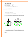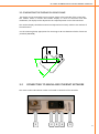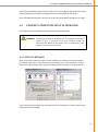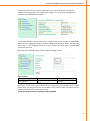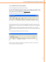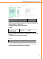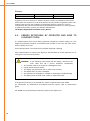
1
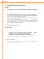
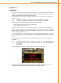
KVL1303-EN-01 KVL-KENN02 8+4-DIGIT NUMBER DISPLAY WITH ETHERNET INTERFACE USER MANUAL 8+4 DIGIT NUMBER DISPLAY WITH ETHERNET INTERFACE KVL-KENN02 USER MANUAL 8+4 DIGIT NUMBER DISPLAY WITH ETHERNET INTERFACE Notice The following conventions are used to indicate and classify precautions in this manual. Always heed the information provided with them. Failure to heed precautions can result in injury to people or damage to property. DANGER Indicates an imminently hazardous situation which, if not avoided, will result in death or serious injury. Additionally, there may be severe property damage. WARNING Indicates a potentially hazardous situation which, if not avoided, could result in death or serious injury. Additionally, there may be severe property damage. CAUTION Indicates a potentially hazardous situation which, if not avoided, may result in minor or moderate injury, or property damage. Trademarks Windows is a registered trademark of Microsoft Corporation in the United States and other countries. The other brand and product names are trademarks or registered trademarks of their respective owners. Introduction We design and manufacture our devices with the feedback from the enterprises of the industry and their specific needs in mind. Our pokayoke systems elaborated this way are robust and due to the sophisticated solutions applied in them, they provide a long maintenance-free lifecycle. These devices are recommended for those firms where one of the following problems has emerged and would like to develop a solution: Frequently occurring errors in production processes; Products must be called back due to installing parts of wrong type; High scrap-costs caused by selecting wrong part; Workers often forget to tighten the screws fixing the part; Workers forget to install one or more parts and this mistake is noticed too late; The pokayoke systems of KVL COMP aid the effective troubleshooting of these errors. © KVL COMP, 2010 All rights reserved. It is forbidden to reproduce or store this document or part of it in any data-retrieval system or transfer it in any form, in any way (mechanically, electronically, photocopying, recording or with any other technique) without prior written permission from KVL COMP. We do no take patent responsibility for the information disclosed here. Also, as KVL COMP is constantly striving to improve its high quality products, the information, included in this guide can change without notice. During the creation of this guide we try to be as accurate, as possible, but KVL COMP does not take responsibility for the possible errors or omissions. Also, KVL COMP does not take any responsibility for the possible damages resulting from using this guide. 8+4 DIGIT NUMBER DISPLAY WITH ETHERNET INTERFACE TABLE OF CONTENTS I. About this Manual .................................................................................................................................1 II. Related guides .......................................................................................................................................1 III. Publication history ................................................................................................................................1 IV. Warranty and Limitations of Liability ...................................................................................................2 V. Application considerations ...................................................................................................................2 VI. Disclaimers ............................................................................................................................................3 VII. Precautions ...........................................................................................................................................3 CHAPTER 1 ..................................................................................................................................................5 OVERVIEW...................................................................................................................................................5 1-1 SHORT INTRODUCTION OF POKAYOKE SYSTEM ..................................................................5 1-2 LOCATION OF THE DISPLAY UNIT IN THE POKAYOKE SYSTEM ............................................5 CHAPTER 2 ..................................................................................................................................................6 TECHNICAL DATA ........................................................................................................................................6 2-1 DIMENSIONS ........................................................................................................................6 2-2 ELECTRICAL SPECIFICATIONS ...............................................................................................7 2-3 ETHERNET NETWORK ..........................................................................................................7 2-4 DISPLAY UNIT .......................................................................................................................8 CHAPTER 3 ..................................................................................................................................................8 MOUNTING AND BINDING ..........................................................................................................................8 3-1 MOUNTING THE DISPLAY ON THE WORKSTATION .............................................................8 3-1-1 Mounting by using metal binder ........................................................................................8 3-1-2 Mounting the display by using clamp ................................................................................9 3-2 CONNECTING TO MAINS AND ETHERNET NETWORK ..........................................................9 CHAPTER 4 ................................................................................................................................................10 SETUP AND OPERATION............................................................................................................................10 4-1 SWITCHING ON THE NUMBER DISPLAY .............................................................................10 4-2 ETHERNET CONNECTION SETUP IN OPERATION ...............................................................11 4-2-1 Open the browser ............................................................................................................11 4-2-2 Ethernet set up crosscable ...............................................................................................12 Device name ......................................................................................................................... 13 IP ADDRESS ........................................................................................................................... 14 Netmask................................................................................................................................ 14 Gateway................................................................................................................................ 14 KVL-KENN02 4-2-3 Ethernet setup on network ............................................................................................. 15 Device name ........................................................................................................................ 17 IP address............................................................................................................................. 17 Netmask ............................................................................................................................... 17 Gateway ............................................................................................................................... 18 4-3 ERRORS DETECTABLE BY OPERATOR AND HOW TO ELIMINATE THEM ............................ 18 8+4 DIGIT NUMBER DISPLAY WITH ETHERNET INTERFACE Read and Understand this Manual! Please read and understand this manual before using the product. Please consult your KVL COMP representative if you have any questions or comments. I . About t hi s Ma nual This guide explains the installation and operation of the product. Before installing and using the product read this guide carefully and be sure to understand its contents. Also read and follow the safety information described in the next chapter. The chapter titled Precautions contains general safety instructions of using the product and the related devices. Chapter 1: Introduces the product and its structural units Chapter 2: Explains the structure of the product. Chapter 3: Explains the installation of the product, the wiring of the power supply and the I/O lines and also the functional testing of the product. Chapter 4: Explains the setup and operation of the product. I I . Rel a t ed g ui de s The following guides give information on the related devices. You can find the necessary information in the following documents. Cat.No. KVL1000 KVL1304 KVL1001 KVL1002 Title of Publication POKAYOKE CONTROL AND DATA ACQUISITION SYSTEM WITH ETHERNET NETWORK 8+4 DIGIT NUMBER DISPLAY WITH ETHERNET INTERFACE NETWORK CABLE ETHERNET PATCH CABLE Description KVL COMP ETHERNET POKAYOKE SYSTEM DESCRIPTION MAINTENANCE MANUAL DATASHEET DATASHEET I I I . P u b l i ca t i on h ist ory The number of the publication is also indicated on the cover of the publication. NUMBER OF PUBLICATION: KVL1303-EN-01 Date of publication September 2010 No. of publication KVL1303-EN-01 Chapter Revised content 1st edition 1 KVL-KENN02 I V. Wa rra n t y a n d L i mi t a t i on s of L i a b i l i t y WARRANTY KVL COMP's exclusive warranty is that the products are free from defects in materials and workmanship for a period of one year (or other period if specified) from date of sale by KVL COMP. LIMITATIONS OF LIABILITY KVL COMP shall not be responsible for special, indirect, or consequential damages, loss of profits or commercial loss in any way connected with the products, whether such claim is based on contract, warranty, negligence, or strict liability. In no event shall the responsibility of KVL COMP for any act exceed the individual price of the product on which liability is asserted. In no event shall KVL COMP be responsible for warranty, repair, or other claims regarding the products unless KVL COMP‘s analysis confirms that the products were properly handled, stored, installed, and maintained and not subject to contamination, abuse, misuse, or inappropriate modification or repair. V. A p p l i ca t i on c o n si d era t i on s SUITABILITY FOR USE The following are some examples of applications for which particular attention must be given. This is not intended to be an exhaustive list of all possible uses of the products, nor is it intended to imply that the uses listed may be suitable for the products: Outdoor use, uses involving potential chemical contamination or electrical interference, or conditions or uses not described in this manual. Installations subject to separate industry or government regulations. Systems, machines, and equipment that could present a risk to life or property. Please know and observe all prohibitions of use applicable to the products. PROGRAMMABLE PRODUCTS KVL COMP shall not be responsible for the user's programming of a programmable product, or any consequence thereof. 2 8+4 DIGIT NUMBER DISPLAY WITH ETHERNET INTERFACE VI . D i scl a i me rs CHANGE IN SPECIFICATIONS Product specifications and accessories may be changed at any time based on improvements and other reasons. It is our practice to change model numbers when published ratings or features are changed, or when significant construction changes are made. However, some specifications of the products may be changed without any notice. When in doubt, special model numbers may be assigned to fix or establish key specifications for your application on your request. Please consult with your KVL COMP representative at any time to confirm actual specifications of purchased products. DIMENSIONS AND WEIGHTS Dimensions and weights are nominal and are not to be used for manufacturing purposes, even when tolerances are shown. PERFORMANCE DATA Performance data given in this manual is provided as a guide for the user in determining suitability and does not constitute a warranty. It may represent the result of KVL COMP's test conditions, and the users must correlate it to actual application requirements. ERRORS AND OMISSIONS The information in this manual has been carefully checked and is believed to be accurate; however, no responsibility is assumed for clerical, typographical, or proofreading errors, or omissions. VI I . P re ca u t i on s This section provides general precautions for using the related devices. The information contained in this section is important for the safe and reliable application of product. You must read this section and understand the information contained before attempting to set up or operate a product. INTENDED AUDIENCE This manual is intended for the following personnel: workers trained to the specific task, working on the assembly stations and on the assembly line, operating the device, work group leaders; professionals responsible for the installation, setup and maintenance of the device. 3 KVL-KENN02 GENERAL PRECAUTIONS The user must operate the product according to the performance specifications described in the operation manuals. Before using the product under conditions which are not described in the manual or applying the product to other systems, machines, and equipment that may have a serious influence on lives and property if used improperly, consult your KVL COMP representative. Make sure that the ratings and performance characteristics of the product are sufficient for the systems, machines, and equipment. This manual provides information for setup and operating the product. Be sure to read this manual before attempting to use the product and keep this manual close at hand for reference during operation. WARNING It is extremely important that a product be used for the specified purpose and under the specified conditions, especially in applications that can directly or indirectly affect human life. You must consult with your KVL COMP representative before applying a product to the above-mentioned applications. SAFETY PRECAUTIONS CAUTION When power is ON or has just been turned OFF, do not touch the power supply, I/O terminals, or the surrounding areas. CAUTION Secure the AC power supply line to the terminal block with a 0.5N·m of torque. Loosening the screw may result in a fire or malfunction. APPLICATION PRECAUTIONS CAUTION 4 On modifying the program, always ensure that switching to MONITOR or RUN mode does not lead to unexpected effects. 8+4 DIGIT NUMBER DISPLAY WITH ETHERNET INTERFACE CHAPTER 1 OVE R VI E W This guide explains the installation, wiring and setup of the KVL-KENN02 Ethernet network display unit and describes it’s operation. The installation, wiring and setup of the product must be accomplished by experienced professionals. The description of operation provides information for the workers working with the pokayoke system. 1- 1 SH ORT I N T RO D UC T I ON OF P OKAY O KE SY ST E M The meaning of the Japanese words Poka-Yoke in free translation: Poka: random, unintentional error, mistake, fault Yoke: elimination, prevention Meaning: mistake-free, error-free work, workstation, technology, process development, in order to avoid human errors. The aim of pokayoke is the full-scale prevention of product defects, waste avoidance, minimization of quality control costs, to provide error-free working conditions and work. To sum up, pokayoke is a system that assists manufacturing and assembling, that helps and – simultaneously – controls the workers. Using pokayoke effectively improves waste avoidance. The KVL-KENN02 is part of the Ethernet network based pokayoke system developed by KVL COMP. 1- 2 LOCATION OF TH E DISPLAY U NIT IN THE POK AYOK E SYSTEM The KVL-KENN002 type Ethernet-controlled display can display 8+4 digits. Its purpose is to display the identification number of the product/unit that is currently located at the workstation (8 digits) and the sequence number (4 digits). 5 KVL-KENN02 For the appropriate operation of the pokayoke system, the workpieces/units entering the workstation must be identified. The identification can be done locally (barcode scanning, RF‐ID tag scanning) or based on data sent by the computer system or PLC controlling the production. The identification data are sent to the pokayoke controller server. The pokayoke controller server transfers the ID number of the workpiece/unit to the KVL‐KENN002 display unit over Ethernet network for display. This way, workers can verify that the identification was appropriate, and the pokayoke system is operating with the correct data. The pokayoke devices of the specific workstation are configured with the data required for the assembly of parts/units corresponding to the ID number shown on the KVL‐KENN002 display. CHAPTER 2 TECHNICAL D ATA 2- 1 DIMENSIONS The KVL-KENN02 display unit is build with a plastic case. 240 mm 276 mm 6 120 mm 240*120*100 mm grey RAL 7032 (on demand: yellow RAL 1001) 165 mm Size of the display case: Colour of the display case: 100mm 8+4 DIGIT NUMBER DISPLAY WITH ETHERNET INTERFACE 2- 2 ELECTRI CA L SPECI FI CATI ONS Power supply: Current drain: Operating range: Operating temperature: Operating humidity: Storage temperature: Storage humidity: Mains circuit connection: Fuse: Suggested power cord: 2- 3 230 V AC 50 Hz 0,4 A (max. 1 A) 100 … 240 V 48 … 62 Hz 5 … 40°C 20 … 90% RH non-condensing -20 … 70°C 10 … 95% RH non-condensing IEC standard connector, the socket is integrated with switch and fuse. 5*20 glass-tube fuse; 230 V 2 A SLOW KVL-POW3 (3 m) ETHERNE T NET W ORK The interface is connected to a standard 10/100 Ethernet network. The industrial Ethernet socket is of type VARIOSUB-RJ45. The suggested Ethernet network cable is KVL-ETN3 (3 m). 7 KVL-KENN02 2- 4 DISPLAY U NIT Height of displayed numbers: Number of displayed digits: 25 mm 8+4 The display unit is placed behind red plexiglas for higher contrast. CHAPTER 3 M OUN T I N G AN D BI N D I N G 3- 1 M OUN T I N G T H E D I SP L AY ON T H E WO RKST AT I ON The display can be mounted by using metal binder or clamp. The required type of mounting should be provided on order. 3-1-1 MOUNTING BY USING METAL BINDER The display can be mounted by using its bent metal binder with borehole. The binder and the one‐screw mounting ensures that the display can be adjusted to the best position both vertically and horizontally. 50° 50° 120° 120° The number display should be mounted and adjusted to be clearly visible to the workers of the workstation. The actual mounting method depends on the environment, the appropriate frame should be individually designed and manufactured. For mounting onto the frame, it has to have an M6 threaded hole or a hole of 6.5 mm diameter. 8 8+4 DIGIT NUMBER DISPLAY WITH ETHERNET INTERFACE 3-1-2 MOUNTING THE DISPLAY BY USING CLAMP The display can be mounted by using its plastic clamp at the back side of the control box. The tubular frame to mount the number display on must be horizontal and after installation, the display can be adjusted to the required position on this horizontal axis. The number display should be mounted and adjusted to be clearly visible to the workers of the workstation. For the mounting clamp appropriate for mounting to 28 mm diameter tubular frames are provided (TRILOGIQ) 50° 50° 3- 2 CONNECTI NG TO MAI NS AND ETHE RNET NE TW ORK The mains socket and Ethernet socket are located on the back of the controller. 1 2 3 4 5 9 KVL-KENN02 1. 2. 3. 4. 5. Ethernet socket On/off switch Glass tube fuse: 5*20 glass tube; 230 V 10 A SLOW Mains (230 V AC) socket MAC address of the controller For connecting to the mains circuit we recommend the type KVL-POW. Ensure that the controller is switched off when you connect the cable. WARNING Risk of electric shock when using wrong or demaged mains connector cable! WARNING Risk of fire and human injury when using demaged, repaired fuses or fuses not of the appropriate type! For connecting to the Ethernet network we recommend the type KVL-ETN cable. CHAPTER 4 SE T UP AN D OP E R AT I ON 4- 1 SWI T C H I N G ON T H E N UM BE R D I SP L AY The device is switched on with the rocker switch located next to the power supply connector. After switching on the equipment, a self-checking method start immediately and display a countdown from 8 to 0 on the upper line of the display (sequence display). During the countdown the display automatically initializes its communication module. 10 8+4 DIGIT NUMBER DISPLAY WITH ETHERNET INTERFACE After the self-checking method there must be a 0 on the last digit of the bottom line of the display (identification number) until getting the first command from the server. After switching off the device, always wait at least 5 seconds before switching it on again! 4- 2 E T H E RN E T C ON N E C T I ON SE T UP I N O P E RAT I ON This chapter contains the display ethernet modul’s setup description. WARNING The Ethernet module of the display unit is configured at testing by experts of KVL, so you have to set only a limited number of parameters (IP address of the display, etc.) on deployment, if the display is connected to a KVL Server. 4-2-1 OPEN THE BROWSER Open your browser with the cookie function enabled. (To enable your Internet Explorer for cookies, right click on your desktop Internet Explorer icon, select Properties, click on the Security tab, and then select the three Enable options as shown in the figure below.) If you cannot execute safety the settings based on the description, contact with the professionals of the KVL COMP. 11 KVL-KENN02 CAUTION Ethernet devices with incorrect configurations can cause serious errors on the network! CAUTION Before completing the operation recheck configuration! CAUTION Do not set Ethernet options on devices connected to the industrial network during production! The system administrators are responsible for the operation of Ethernet networks. Before start to set up the display ethernet network you should get to know the following datas from the network operator: IP address which has to be set up on display IP address of the gateway (if this necessary); the subnet mask; Note the following data, because it must be set on the server program: the IP address of the display; The place of the display in the factory (assembly line, workplace number, etc.). Before setting, make sure that the display is connected to the network and that the device is on. We recommended, that don’t connect the display to the plant Ethernet network, but programmed direct with cable connection (crossable). 4-2-2 ETHERNET SET UP CROSSCABLE Connect the display to the computer. Type 192.168.128.170 in the Address box and then press Enter. WARNING If you use other browsers, remember to enable the functions to „allow cookies that are stored on your computer” or „allow persession cookies” MiiNePortE1 modules only uses cookies for password transmission. You can read more about „cookie” permission in paragraph 4-2-1. 12 8+4 DIGIT NUMBER DISPLAY WITH ETHERNET INTERFACE The web console will open. On this page, you can see a brief description of the web console’s function groups in the left part of the page. You can also see a configuration overview of you MiiNePort E1 module. On the web console, the left panel is the navigation panel and contains an expandable menu tree for navigating among the various settings and categories. When you click on a menu item in the navigation panel, the main window will display the corresponding options for that item Open the „Basic Settings” and than the „Network Settings” menu. DEVICE NAME Setup 1-39 characters Default setup NP [model name]_[Serial No.] Necessity Optional This option can be used to specify the location or application of the module, which may be useful when managing more than one module on the network. With this option we can indicate the place of the module and its task. The display shipped with the Equipment Name KENN02. 13 KVL-KENN02 IP ADDRESS Setup E.g., 192.168.1.1 (IP addresses of the form x.x.x.0 and x.x.x.255 are invalid.) Default setup Necessity 192.168.127.254 Required An IP address is a number assigned to a network device, such as a computer, as a permanent address on the network. Computers use the IP address to identify and talk to each other over the network. Choose a proper IP address which is unique and valid in your network environment. The display shipped with the IP address 192.168.128.170. NETMASK Setup E.g., 255.255.255.0 Default setup 255.255.255.0 Necessity Required If the address is on the same network segment as the module, a connection is established directly from the module. Otherwise, the connection is established through the default gateway. The display shipped with the default 255.255.255.0 subnet mask. GATEWAY Setup E.g., 192.168.1.1 Default setup None Necessity Optional A gateway acts as an entrance to another network. Usually, the computers that control traffic within the network or at the local Internet service provider are gateway nodes. The module needs to know the IP address of the default gateway computer in order to communicate with the hosts outside the local network environment. For correct gateway IP address information, consult your network administrator. The display shipped with the default setup („None”). 14 8+4 DIGIT NUMBER DISPLAY WITH ETHERNET INTERFACE 4-2-3 ETHERNET SETUP ON NETWORK Connect the display and the computer to the network. Start the „MOXA Nport Search Utility” program on the computer. The program can be found on the „KVL COMP POKAYOKE CD” shipped with the POKAYOKE system or can be downloaded from the KVL COMP website (www.kvlcomp.hu) Open the NPort utility and click on „Search” icon. 5 The Broadcast Search feature is used to find all MiiNePort E1 modules connected to the same LAN network as your computer. After a MiiNEPort E1 is found, you can change its IP address. The Broadcast Search is based on MAC address instead of IP address, so it can find all modules connected to the LAN network, even if they are not on to the same subnet as the host. The seraching window displays the process of searching. After the search is complete, all MiiNePort E1 modules connected to the network are listed in the NPort Search Utility window. 15 KVL-KENN02 The configuration of the selected MiiNePort E1 can be modified by clicking the console icon to open the web console. WARNING If you use other browsers, remember to enable the functions to „allow cookies that are stored on your computer” or „allow persession cookies” MiiNePortE1 modules only uses cookies for password transmission. You can read more about „cookie” permission in paragraph 4-2-1. On the left side of the page you can find a list of web console function groups. In addition, the configuration summary of your MiiNePortE1 module is displayed here. The left pane of the web console displays a tree menu you can use to navigate between properties and categories. Clicking a menu item displays the options of the given item in the main window. 16 8+4 DIGIT NUMBER DISPLAY WITH ETHERNET INTERFACE Open the „Basic Settings” than the „Network Settings” menu. DEVICE NAME Setup 1-39 characters Default setup NP [model name]_[Serial No.] Necessity Optional This option can be used to specify the location or application of the module, which may be useful when managing more than one module on the network. With this option we can indicate the place of the module and its task. The display shipped with the Equipment Name KENN02. IP ADDRESS Setup E.g., 192.168.1.1 (IP addresses of the form x.x.x.0 and x.x.x.255 are invalid.) Default setup Necessity 192.168.127.254 Required Choose an appropriate IP address which is individual and valin in your network environment. The display shipped with the IP Address 192.168.128.170. NETMASK Setup E.g., 255.255.255.0 Default Setup 255.255.255.0 Necessity Required If the address is on the same network segment as the module, a connection is established directly from the module. Otherwise, the connection is established through the default gateway. The display shipped with the default 255.255.255.0 subnet mask. 17 KVL-KENN02 GATEWAY Setup E.g., 192.168.1.1 Default Setup None Necessity Optional A gateway acts as an entrance to another network. Usually, the computers that control traffic within the network or at the local Internet service provider are gateway nodes. The module needs to know the IP address of the default gateway computer in order to communicate with the hosts outside the local network environment. For correct gateway IP address information, consult your network administrator. The display shipped with the default setup („None”). 4- 3 ERR ORS D ET ECT A BLE BY OP E RAT O R AND HOW T O ELIMINATE THEM If a communication error occurs during operation (temporary network outage, etc.) the display automatically initializes its communication module. In this case the same countdown is shown as on start. Until communication is restored, the last number displayed is flashing. After communication is restored, the display is switched back to normal operation on receiving the next correct data packet. WARNING In the following cases switch off the display, disconnect network cable and call a service technician immediately: The network cable or its connector is damaged or worn. Liquids penetrated the display. The display was exposed to rain or other forms of water. The display fell or its case is damaged. The operation of the display is unstable or the display is malfunctioning. The display emits unusual noise, smoke or unpleasant smell. If the period of warranty is not expired yet, repairs are performed by KVL COMP. For information on maintenance and beyond warranty repairs, refer to maintenance guide. KVL COMP also performs beyond warranty repairs of the display unit 18 KVL COMP Vezérléstechnikai Kft. 2500 Esztergom, Nagy Sándor József u. 3. HUNGARY Tel.: 00-36-33-501-616 Fax: 00-36-33-501-615 www.kvlcomp.eu [email protected] KVL COMP s.r.o. Komenského 35, 94301 Štúrovo SLOVAKIA Tel.: 00-36-33-501-616 Fax: 00-36-33-501-615 www.kvlcomp.eu [email protected]