1
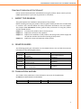
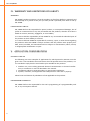
KVL1290-EN-01 KVL-ATQ06EEU SCREWDRIVER CONTROL BOX WITH ETHERNET NETWORK USER MANUAL KVL-ATQ06EEU USER MANUAL SCREWDRIVER CONTROL BOX WITH ETHERNET NETWORK Notice The following conventions are used to indicate and classify precautions in this manual. Always heed the information provided with them. Failure to heed precautions can result in injury to people or damage to property. DANGER Indicates an imminently hazardous situation which, if not avoided, will result in death or serious injury. Additionally, there may be severe property damage. WARNING Indicates a potentially hazardous situation which, if not avoided, could result in death or serious injury. Additionally, there may be severe property damage. CAUTION Indicates a potentially hazardous situation which, if not avoided, may result in minor or moderate injury, or property damage. Trademarks Windows is a registered trademark of Microsoft Corporation in the United States and other countries. The other brand and product names are trademarks or registered trademarks of their respective owners. Introduction We design and manufacture our devices with the feedback from the enterprises of the industry and their specific needs in mind. Our pokayoke systems elaborated this way are robust and due to the sophisticated solutions applied in them, they provide a long maintenance-free lifecycle. These devices are recommended for those firms where one of the following problems has emerged and would like to develop a solution: Frequently occurring errors in production processes; Products must be called back due to installing parts of wrong type; High scrap-costs caused by selecting wrong part; Workers often forget to tighten the screws fixing the part; Workers forget to install one or more parts and this mistake is noticed too late; The pokayoke systems of KVL COMP aid the effective troubleshooting of these errors. © KVL COMP, 2010 All rights reserved. It is forbidden to reproduce or store this document or part of it in any data-retrieval system or transfer it in any form, in any way (mechanically, electronically, photocopying, recording or with any other technique) without prior written permission from KVL COMP. We do no take patent responsibility for the information disclosed here. Also, as KVL COMP is constantly striving to improve its high quality products, the information, included in this guide can change without notice. During the creation of this guide we try to be as accurate, as possible, but KVL COMP does not take responsibility for the possible errors or omissions. Also, KVL COMP does not take any responsibility for the possible damages resulting from using this guide. SCREWDRIVER CONTROL BOX WITH ETHERNET NETWORK CONTENTS I. About this Manual.......................................................................................................................1 II. Related guides.............................................................................................................................1 III. Publication history ......................................................................................................................1 IV. Warranty and Limitations of Liability .........................................................................................2 V. Application considerations .........................................................................................................2 VI. Disclaimers..................................................................................................................................3 VII. Precautions .................................................................................................................................3 CHAPTER 1 ........................................................................................................................................5 OVERVIEW ...................................................................................................................................5 1-1 Short introduction of pokayoke systems ..............................................................................5 1-2 The location of the SCREWDRIVER controller in the pokayoke system ................................5 CHAPTER 2 ........................................................................................................................................6 TECHNICAL DATA ..............................................................................................................................6 2-1 Dimensions ............................................................................................................................6 2-2 Electrical data ........................................................................................................................7 2-3 Ethernet network ..................................................................................................................7 CHAPTER 3 ........................................................................................................................................8 INSTALLATION AND WIRING .............................................................................................................8 3-1 Installing the controller at the workplace .............................................................................8 3-2 Connecting to mains and Ethernet network .........................................................................8 3-3 External light column connector ...........................................................................................9 3-4 external key switch connector ............................................................................................10 3-5 „TEST” connector ................................................................................................................10 3-6 Screw quantity display ........................................................................................................11 CHAPTER 4 ......................................................................................................................................12 SETUP AND OPERATION .................................................................................................................12 4-1 Switching on the controller .................................................................................................12 4-2 Controls ...............................................................................................................................12 4-3 Light and audible signs ........................................................................................................13 4-4 work process .......................................................................................................................14 4-5 Daily checks before work ....................................................................................................16 KVL-ATQ06EEU SCREWDRIVER CONTROL BOX WITH ETHERNET NETWORK Read and Understand this Manual! Please read and understand this manual before using the product. Please consult your KVL COMP representative if you have any questions or comments. I . AB OUT T H I S M AN UA L This guide explains the installation and operation of the product. Before installing and using the product read this guide carefully and be sure to understand its contents. Also read and follow the safety information described in the next chapter. The chapter titled Precautions contains general safety instructions of using the product and the related devices. Chapter 1: Chapter 2: Chapter 3: Chapter 4: Introduces the product and its structural units Explains the structure of the product. Explains the installation of the product, the wiring of the power supply and the I/O lines and also the functional testing of the product. Explains the setup and operation of the product. I I . RE L AT E D G UI D E S The following guides give information on the related devices. You can find the necessary information in the following documents. Cat.No. KVL1210 KVL1001 KVL1002 KVL1310 KVL1163 KVL1217 Title of Publication SCREWDRIVER CONTROL BOX WITH ETHERNET NETWORK POWER CABLE ETHERNET PATCH CABLE GREEN/YELLOW/RED LIGHT-TOWER WITH ACOUSTIC SIGNAL ACKNOWLEDGEMENT MODULE RADIO TRANSMITTER MODULE FOR BOSCH SEC EXACT SCREWDRIVER Description MAINTENANCE MANUAL DATASHEET DATASHEET DATASHEET DATASHEET DATASHEET I I I . P UBL I C AT I ON H I ST ORY The number of the publication is also indicated on the cover of the publication. NUMBER OF PUBLICATION: KVL1209-EN-01 Date of Publication 12. 2010. No. of Publication KVL1209-EN-01 Chapter Revised content 1st edition 1 KVL-ATQ06EEU I V. W AR RAN T Y A N D L I M I T AT I ON S OF L I A BI L I T Y WARRANTY KVL COMP's exclusive warranty is that the products are free from defects in materials and workmanship for a period of one year (or other period if specified) from date of sale by KVL COMP. LIMITATIONS OF LIABILITY KVL COMP shall not be responsible for special, indirect, or consequential damages, loss of profits or commercial loss in any way connected with the products, whether such claim is based on contract, warranty, negligence, or strict liability. In no event shall the responsibility of KVL COMP for any act exceed the individual price of the product on which liability is asserted. In no event shall KVL COMP be responsible for warranty, repair, or other claims regarding the products unless KVL COMP‘s analysis confirms that the products were properly handled, stored, installed, and maintained and not subject to contamination, abuse, misuse, or inappropriate modification or repair. V. AP P L I C AT I ON C ON SI D E RAT I ON S SUITABILITY FOR USE The following are some examples of applications for which particular attention must be given. This is not intended to be an exhaustive list of all possible uses of the products, nor is it intended to imply that the uses listed may be suitable for the products: Outdoor use, uses involving potential chemical contamination or electrical interference, or conditions or uses not described in this manual. Installations subject to separate industry or government regulations. Systems, machines, and equipment that could present a risk to life or property. Please know and observe all prohibitions of use applicable to the products. PROGRAMMABLE PRODUCTS KVL COMP shall not be responsible for the user's programming of a programmable product, or any consequence thereof. 2 SCREWDRIVER CONTROL BOX WITH ETHERNET NETWORK VI . D I SC L AI M E RS CHANGE IN SPECIFICATIONS Product specifications and accessories may be changed at any time based on improvements and other reasons. It is our practice to change model numbers when published ratings or features are changed, or when significant construction changes are made. However, some specifications of the products may be changed without any notice. When in doubt, special model numbers may be assigned to fix or establish key specifications for your application on your request. Please consult with your KVL COMP representative at any time to confirm actual specifications of purchased products. DIMENSIONS AND WEIGHTS Dimensions and weights are nominal and are not to be used for manufacturing purposes, even when tolerances are shown. PERFORMANCE DATA Performance data given in this manual is provided as a guide for the user in determining suitability and does not constitute a warranty. It may represent the result of KVL COMP's test conditions, and the users must correlate it to actual application requirements. ERRORS AND OMISSIONS The information in this manual has been carefully checked and is believed to be accurate; however, no responsibility is assumed for clerical, typographical, or proofreading errors, or omissions. VI I . P RE C A UT I ON S This section provides general precautions for using the related devices. The information contained in this section is important for the safe and reliable application of product. You must read this section and understand the information contained before attempting to set up or operate a product. INTENDED AUDIENCE This manual is intended for the following personnel: workers trained to the specific task, working on the assembly stations and on the assembly line, operating the device, work group leaders; professionals responsible for the installation, setup and maintenance of the device. 3 KVL-ATQ06EEU GENERAL PRECAUTIONS The user must operate the product according to the performance specifications described in the operation manuals. Before using the product under conditions which are not described in the manual or applying the product to other systems, machines, and equipment that may have a serious influence on lives and property if used improperly, consult your KVL COMP representative. Make sure that the ratings and performance characteristics of the product are sufficient for the systems, machines, and equipment. This manual provides information for setup and operating the product. Be sure to read this manual before attempting to use the product and keep this manual close at hand for reference during operation. WARNING It is extremely important that a product be used for the specified purpurpose and under the specified conditions, especially in applications that can directly or indirectly affect human life. You must consult with your KVL COMP representative before applying a product to the above-mentioned applications. SAFETY PRECAUTIONS CAUTION When power is ON or has just been turned OFF, do not touch the power supply, I/O terminals, or the surrounding areas. CAUTION Secure the AC power supply line to the terminal block with a 0.5N·m of torque. Loosening the screw may result in a fire or malfunction. APPLICATION PRECAUTIONS CAUTION 4 On modifying the program, always ensure that switching to MONITOR or RUN mode does not lead to unexpected effects. SCREWDRIVER CONTROL BOX WITH ETHERNET NETWORK CHAPTER 1 OVERVIEW This guide explains the installation, wiring and setup of the KVL-ATQ06EEU Ethernet network controller and describes its operation. The installation, wiring and setup of the product must be accomplished by experienced professionals. The description of operation provides information for the workers working with the poka-yoke system. 1-1 SHORT INTRODUCTION OF POKAYOKE SYSTEMS The meaning of the Japanese words Poka-Yoke in free translation: Poka: random, unintentional error, mistake, fault Yoke: elimination, prevention Meaning: mistake-free, error-free work, workstation, technology, process development, in order to avoid human errors. The aim of poka-yoke is the full-scale prevention of product defects, waste avoidance, minimization of quality control costs, to provide error-free working conditions and work. To sum up, poka-yoke is a system that assists manufacturing and assembling, that helps and – simultaneously – controls the workers. Using poka-yoke effectively improves waste avoidance. The KVL-ATQ06EEU is part of the Ethernet network based poka-yoke system developed by KVL COMP. 1-2 THE LOCATION OF THE SCREWDRIVER CONTROLLER IN THE POKAYOKE SYSTEM The torque wrench Poka-yoke’s aim is to help the operator’s job, and reduce the error possibilities. During producing any kind of device often happens that the components are connected together with bolting. The bolting is strongly influencing the final products usability, durability and reliability. In many cases the operators during a day torque hundreds of screws. Unavoidably it occurs that they miss a screw or the tightening is not done properly. The KVL-ATQ06EEU screwdriver controller with Ethernet network what was developed by the KVL Comp. helps to eliminate these occurring errors. 5 KVL-ATQ06EEU CHAPTER 2 TECHNICAL D ATA 2-1 DIMENSIONS The KVL-ATQ06EEU controller is installed in a metal plate case. Dimensions of the controller box: Colour of the controller box: 6 400*300*210 mm Grey RAL 7032 SCREWDRIVER CONTROL BOX WITH ETHERNET NETWORK 2-2 ELECTRICAL DATA Supply voltage: Current drain: Operating range: Operating temperature: Operating humidity: Storage temperature: Storage humidity: Mains circuit connection: Fuse: Recommended mains connector cable: 230 V AC 50 Hz 10 A 100 … 240 V 48 … 62 Hz 5 … 40°C 20 … 90% RH non-condensing -20 … 70°C 10 … 95% RH non-condensing IEC standard connector, with fuse and switch 5*20 glass-tube; 230 V 10 A SLOW KVL-POW 2-3 ETHERNET NETWORK The controller can be connected to standard 10/100 Ethernet network. The industrial Ethernet socket is of type VARIOSUB-RJ45. The recommended Ethernet cable is of type KVL-ETN. 7 KVL-ATQ06EEU CHAPTER 3 INSTALLATION AND WIRING 3-1 INSTALLING THE CONTROLLER AT THE WORKPLACE The control box will be installed on TRILOGIQ shelf system. The plastic clamps, what is necessary for the installation, is fixed to the back cover of the control box (Accessory). 3-2 CONNECTING TO MAINS AND ETHERNET NETWORK The sockets are located on the side of the controller. 1 4 5 6 7 8 2 1. 2. 3. 4. 5. 6. 7. 3 Mains (230 V AC) socket; Glass tube fuse: 5*20 glass tube; 230 V 2A SLOW; On/off switch; Ethernet socket; Light column connector (KVL-LTW02); Key switch connector (KVL-KSW01); TEST connector. SCREWDRIVER CONTROL BOX WITH ETHERNET NETWORK For connecting to the mains circuit we recommend the type KVL-POW cable. Ensure that the controller is switched off when you connect the cable. WARNING Risk of electric shock when using wrong or damaged mains connector cable! WARNING Risk of fire and human injury when using damaged, repaired fuses or fuses not of the appropriate type! For connecting to the Ethernet network we recommend the type KVL-ETN cable. The AS-i network plug is standard M12 sensor plug. 3-3 EXTERNAL LIGHT COLUMN CONNECTOR The device that can be connected: KVL-LTW02 Light column, green/yellow/red light and audible signal. M12, 5 pole, socket. Wire colours: According to Euro-Norm EN 50044. We deliver the KVL-LTW02 module with a 2m long cable. Wire color 1 2 3 4 5 Brown White Blue Black Grey Horn Red Green Yellow Common 9 KVL-ATQ06EEU 3-4 EXTERNAL KEY SWITCH CONNECTOR The connectable device: KVL-KSW02 Error acknowledging module, with SIEMENS E7 key switch, for the controllers delivered to the VW group. M12, 4 pole, socket. Wire colors: according to Euro-Norm EN 50044. We deliver the KVL-KSW02 module with a 2m long cable. Wire color 1 2 3 4 5 Brown White Blue Black grey Switch Switch Not in use Not in use Not in use 3-5 „TEST” CONNECTOR The connectable device: KVL-TQ-TEST Special device for switching the SCREWDRIVER controllers to „TEST” mode. M12, 4 pole, male. Wire colours: According to Euro-Norm EN 50044. The KVL-TQ-TEST is a special device, what if it is connected the controller senses it. The operation of it is depending on communication, disables all functionalities of the control system. The tools are usable as a normal tool. 10 SCREWDRIVER CONTROL BOX WITH ETHERNET NETWORK 3-6 SCREW QUANTITY DISPLAY On the front panel of the device there is a 3x2 piece 7 segment display. The screwdriver controller can control 3 tools. For distinguishing these tools we are using 3 different color codes. The displays on the front panel are colored to yellow, blue and brown. Each one belongs to one tool. It is advisable to indicate these colors on the tools as well. The displays show the current quantity of screw necessary for the component (from 00 to 99). To one display 3 tools can be assigned. From the programmed tools always only one is active at a time, the other 2 are spare ones. The quantity of screws necessary shown on the display always decreases with one after each tightening. In case if all the displays value reaches zero the controller considers the job as done. 11 KVL-ATQ06EEU CHAPTER 4 SE T UP AN D OP E R AT I ON 4-1 SWITCHING ON THE CONTROLLER The device is switched on with the rocker switch located next to the power supply connector. After switching off the device, always wait at least 5 seconds before switching it on again! 4-2 CONTROLS On the controllers front panel there is a white light/button installed what indicates if the controller is turned on. The pushbutton has a „Lamptest” function. The error messages are indicated and the acknowledging is done with the connected devices (KVL-LTW02, KVL-KSW02). 6 5 KVL-LTW02 4 3 1 2 7 12 KVL-KSW02 SCREWDRIVER CONTROL BOX WITH ETHERNET NETWORK 1. POWER ON INDICATOR LIGHT: If the controller is on, the „POWER” labelled light glows. The pushbutton has a „Lamptest” function. 2. SCREW QUANTITY DISPLAY: On the front panel of the device there is a 3x2 piece 7 segment display. The SCREWDRIVER controller can control 3 tightening cases. KVL-LTW02 GREEN/YELLOW/RED LIGHT-TOWER WITH ACOUSTIC SIGNAL 3. SIGNAL POST, GREEN LAMP: Glows, if the all of the screw quantity displays are 00. 4. SIGNAL POST, YELLOW LAMP: In case of server error it glows (with the red [4] one) 5. SIGNAL POST, RED LAMP: In case of error it glows. 6. SIGNAL POST, AUDIBLE SIGNAL: In case of control error audible signal can be heard. KVL-KSW02 KEY SWITCH MODULE WITH AS-I CONTROLLER 7. ACKNOWLEDGING ERRORS: Errors are acknowledged using the E7 key switch. 4-3 LIGHT AND AUDIBLE SIGNS NO AUDIBLE OR VISIBLE SIGNALS Indicates normal operation. THE GREEN LIGHT IS ON, NO AUDIBLE SIGNALS The device completed the production cycle and sends an IO signal. THE RED LIGHT IS ON An error occurred during the cycle. THE YELLOW AND THE RED LIGHTS ARE ON Communication error occurred. THE DEVICE GIVES AN AUDIBLE SIGNAL In case of control error audible signal can be hearing. 13 KVL-ATQ06EEU 4-4 WORK PROCESS The controller controls up to 3 different tools. In every case only one screwdriver is active. By default every screwdriver is disabled. The screwdriver controller receives the necessary data from the server. This data contains the quantity of screws necessary for all 3 tools to the work piece at the work station. On the 7 segment display on the front panel of the device the necessary quantity of screws appear. The controller enables the screwdriver what we have to work with (the belonging display is not showing “00”). If a work piece arrives to the station where is no tightening necessary (on the display ”00 00 00” will appear), the device will switch to “work OK” mode, and all 3 displays will be erased. The screwdriver stays disabled if there is no work needs to be done by it. At this time we can start the tightening of the appropriate screw. The amount of tightening necessary with the tool is shown on the 7 segment display always decreases with one after each tightening. In case we loosen a screw, the display (depending on the programming mode) counts back one, or goes back to the original numerical value. If a tools displayed value reaches “00” the corresponding screwdriver will be disabled. After tightening the last screw the display will show zero, the light columns green light will glows continuously, indicating that the work is done. At this time the device sends a “work OK” message to the server and all the torque wrenches are disabled. Waiting for the next tools data. The controllers operation is illustrated with the following example: 14 SCREWDRIVER CONTROL BOX WITH ETHERNET NETWORK In the system for the three tools three torque wrenches are connected, one wrench to each case. According to the example with the yellow code colored wrench 2, with the blue 1 and with the brown 0 bolts has to be tighten. 1. Starting to work. The server (or controller PLC) at starting gives the tightening parameters to the controller. With the yellow code colored wrench 2 screws (on its display 2), with the blue wrench 1 screw (on its display 1) has to be tighten. With the brown code coloured wrench there is no work to be done on this work piece (On its display is “00” and the rotation is disabled). 2. With the yellow code colored wrench 1 screw was tighten. Under the yellow code colored display, we will see “1” (the rest of the necessary tightening). 3. With the blue code colored wrench 1 screw was torque. With this wrench the work is done. Under the blue code colored display, we will see “00”. The controller disables the rotation of the wrench. 4. At the second process with the yellow code colored wrench the tighten screw is not the correct screw (the screw is longer than it should be, the screw is oblique). the operator loosens the bolt. The controller counts back one, under the yellow code colored display we will see ”2” (the rest of the necessary tightening). 5. With the yellow code colored wrench 1 screw was tighten. Under the yellow code colored display we will see “1” (the rest of the necessary tightening). 6. With the yellow code colored wrench 1 screw was tighten. With this wrench the work is done. Under the blue code colored display we will see “00”. The controller disables the rotation of the wrench. The operator finished all the work to be done (all three displays show”00”). The controller sends a work OK message to the server. 15 KVL-ATQ06EEU 4-5 DAILY CHECKS BEFORE WORK Daily routine check of control cabinet: Cabinet door is closed: Proper ventilation and protection of the inner parts are only provided with closed cabinet door! Touching the inner parts can cause electric shock. Via the open door dust can penetrate the cabinet. The accumulating dust decreases cooling efficiency and leads to a higher probability of failure. If any device failed the above checks, immediately call maintenance service! WARNING In the following cases switch off the control box, disconnect network cable and call a service technician immediately: - The network cable or its connector is damaged or worn. - Liquids penetrated the control box. - The control box was exposed to rain or other forms of water. - The control box fell or its case is damaged. - The operation of the control box is unstable or the control box is malfunctioning. The control box emits unusual noise, smoke or unpleasant smell. 16 KVL COMP s.r.o. Komenského 35, 94301 Štúrovo SLOVAKIA Tel.: 00-36-33-501-616 Fax: 00-36-33-501-615 www.kvlcomp.eu [email protected] KVL COMP Vezérléstechnikai Kft. H-2500 Esztergom, Nagy Sándor József utca 3. HUNGARY Tel.: 00-36-33-501-616 Fax: 00-36-33-501-615 www.kvlcomp.eu [email protected]