1
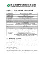
User’s Manual For CMC-MX Soft Starter Version: 1.0 Date: 2014.04.30 1 Safety Precautions The main circuit power will have dangerous voltage when it gets power supply. The input terminals (1L1, 3L2, 5L3) can not be connected with output terminals (2T1, 4T2, 6T3). The soft starter ’s output terminals (2T1, 4T2, 6T3) can not be connected with compensation capacitor or sensitive resistance. When soft starter and frequency inverter are standby mutually, the output end has to be isolated from each other. Do not attempt to repair the damaged device, please contact supplier directly. The temperature of the heat sink may be higher. Do not supply reverse power on the output end of soft starter. The high voltage always exists on the output side when starting or stopping soft starter. 2 CONTENTS Foreword.................................................. .............. .............. .....5 Chapter 1. Functions and Features of CMC-MX Soft Starter . ..........6 1.1 Functions ........................................... .............. .............. .....6 1.2 Features .......................................... .............. .............. ........6 Chapter2. Receiving checking.................. .............. ......................8 Chapter3.Usage conditions and installation............ .............. ........ 10 3.1 Usage Conditions.................. .............. ................................. .10 3.2 Installation Direction.............. .............. .............. .................10 3.3 Installation Space................... .............. .............. .................10 3.4 Circuit Installation............ .............. .............. ......................1 0 Chapter4.Circuit Connection................. .............. ........................ 11 4.1 Basic Wiring Diagram.......................... .............. ................... 11 4.2 Inside Delta Connection Diagram............... .............. ..............11 4.3 Typical Application Wiring Diagram............. .............. ............1 2 4.4 Terminal Description........................ .......... .......... ................1 3 Chapter5.Display and Operating Instructions....... .......... ...............1 4 5.1 Panel Diagram.................................. .......... .......... ............... 14 5.2 Key Function Description................. .......... .......... ................ 14 5.3 Display Status Description............... .......... .......... ..................1 5 5.4 Modify Parameter Operating Procedures..... .......... .................. 15 Chapter 6. Soft Starter Control Mode.................. .......... .......... .....1 7 6.1 Current Limit Soft Start......................... .......... .......... ........... .17 6.2 Voltage Ramp Start............................... .......... .......... ........... . 17 6.3 Sudden Jump Torque Soft Start.................. .......... .......... ........ .18 6.4 Freewheel Stop.................................. .......... .......... .............. ..18 6.5 Soft Stop....................................... .......... .......... .......... ....... ..18 Chapter 7. Parameter and Description.......... .......... .......... ............ .20 7.1 Start-stop Control Parameter Menu C000-C016 A total of 17 Parameters............ ............... .............2 0 7.2 Motor Protection Parameters Menu C100-C116 A total of 17 Parameters ................... .......... ......... ..20 7.3 Port Set Parameters C200-C216 A total of 17 Parameters............. ........ ........ .......... ......... .......20 7.4 Record Function Parameters C300-C316A total of 17 Parameters................ .............. .......... .21 7.5 Function Description........................... .......... .......... ............ ...21 Chapter 8. Fault Detection and Exclusion........ .......... .....................2 5 8.1 Error Code Table................................ .......... .......... ............. ...25 8.2 Trouble Clearing............................... .......... .......... ............... .26 Chapter9. Communication and Control........ .......... ....................... 27 3 9.1 Contents of Agreement........................ .......... ......... . ... ........ .27 9.2 Bus Structure.................................. .......... ........ ... ............... .27 9.3 Protocol Description............................ .......... ...... . ... .......... .27 9.4 Communication Frame Structure....................... .......... .. ......... 27 9.5 Address Description................................. .......... .......... ......... 28 9.6 Control Command Parameter Address.................. .......... ... ..... 29 9.7 Function Code Overview............................. ........... ........ ....... 29 9.8 Communication Time Interval.................... .. ................... ...... 30 9.9 Precautions....................................... .................... ........... ... 30 9.10 Communication Fault Code Analysis....... .......... ............... .....3 0 Chapter10. Routine Maintenance.................. .......... .......... .......... ... 32 Schedule1: Specifications and Accessories Selection (Take 380V as an example) .................... ................ .... .......... .......... .................. .... 32 Schedule2: Soft starters shape and hole size (Unit: mm. Take 380V as an example) .............. ................ . .......... .......... ....... .......... .......... .. 33 Schedule3: Soft Starters Selection...................... .......... ... .......... .... 33 Schedule4: The basic setup software for different applications(The following settings for reference only) . . .......... .......... .......... ..........3 3 4 Foreword Thank you for using CMC-MX motor soft starter that produced by Xi’an Spread Electric Co., Ltd. In order to exhibit soft starter function sufficiently, please operate it correctly according to the procedures and ensure the operators ’ safety. Please read this user ’s manual before you use it. When you meet difficult problems that can not find in this manual, please contact Spread Electric Co., Ltd or local dealer. We will be happy to serve you. 5 Chapter 1. Functions and Features of CMC-MX Soft Starter 1.1 Functions CMC-MX motor soft starter is a kind of new motor starter and protection devices which combines power electronics technology, microprocessor and automatic control. It can start / stop motor smoothly, which avoids issues of shocks between mechanical and electrical caused by direct starting, star / delta starting, auto decompression starting and other traditional start mode. It can also effectively reduce the starting current and distribution capacity, to avoid capacity investment. Meanwhile, current transformers and contractors are integrated in CMC-MX soft starter, users do not need to connect them externally. 1.2 Features ★Various start-up mode User can select current-limit starting mode or voltage ramp starting mode. In order to meet site requirements in maximum extent and to achieve the best start effect, you can also impose a programmable jump starting and starting current-limit under each mode. ★High reliability High-performance microprocessor makes digital processing on control system, it avoids excessive adjustment on analog lines and achieves excellent accuracy and speed of execution. ★Strong anti-jamming performance All external control signals use Photoelectric isolation and set a different anti-noise level. It fits for special industrial environment application.. ★Easy adjustment method With wide application range of control system, easy and intuitive adjustment. Through a variety of function options to match different types of control object. ★Optimized structure Unique compact design of internal structure, particularly user-friendly make it integrated into existing system. It saves costs of current transformer and bypass contactor costs for users. ★Adaptive power frequency Power frequency 50/60 Hz, adaptive function, user-friendly. ★Analog output 4-20mA current output function, user-friendly ★MODBUS-RTU Communication 6 During network communications, it can connect up to 32 devices. Users can achieve the purpose of automatic communication by setting baud rate, communication address. The setting range of communication address is 1-32, The factory value is 1. The setting range of communication address is 0,2400; 1,4800; 2,9600; 3,19200. The factory value is 2 (9600). ★Improved protection function A variety of motor protection functions (Such as over-current, input/output default phase, thyristor short circuit, overheat protection, leakage detection, electronic thermal overload, internal contactor fault, phase current imbalance, etc.) ensures that motor and soft starter will not be damaged in case of failure or malfunction. ★Easy to maintain Monitoring signal coding system consists of four digital display, which monitors system equipment ’s working conditions, while providing rapid fault diagnosis. 7 Chapter 2. Receiving checking Each soft starter have been fully functional and operational tests in the factory, Please check as the following steps after getting and unpacking device. If there is any problem, please contact the supplier immediately. 1. Check the nameplate to confirm the products are whether you order. (1) Soft starter nameplate description (2)Soft starter model description 8 (3)Soft starter item number description 2. Check the product for any damage in transit, such as housing depression, deformation, internal wiring, connectors loosening. 3. Check whether it has product certification, warranty card, packing list, product manual ans so on. 4. Once product out of factory, its guarantee keeps in accordance with the warranty. Please carefully fill in the warranty card, and send it to Xi’an Spread Electric Co., Ltd or local suppliers. 9 Chapter 3. Usage conditions and installation 3.1 Conditions of usage 3.2 Installation Direction The soft starter should be mounted vertically, in order to ensure good ventilation and cooling conditions. 3.3 Installation Space Leave enough space for heating dissipation around the device and keep a distance between device and the wall for easy maintenance (See Schedule 3). If need to select fans, please download the fans ’ sizes from our website (www.xichi.cn) 3.4 Circuit Installation The main circuit should be upper lower, cable should ensure adequate ampacity. Peripheral accessories election, please refer to Schedule 1. 10 Chapter 4. Circuit Connection 4.1 Basic Wiring Diagram Soft starter terminal 1L1, 3L2, 5L3 connect to three-phase power. Terminal 2T1, 4T2, 6T3 connect to motor. No need to connect external bypass contactors, soft starters can choose whether detect phase sequence or not by setting parameter. 4.2 Inside delta connection diagram If adopt connect by inside delta connection, users must connect strictly accordance with the following figure. If not, the motor or soft starter may be damaged. The machine will judge the motor wiring before starting motor, if the wiring errors, the soft starter will reported failures. 11 4.3 Typical application wiring diagram 12 Note: The single node control is showed in the figure. Node closed, soft starter starts, node open, soft starter stops.But pay attention to wiring to LED panel start-up operation is invalid. 3, 4, 5 terminal start-up signal is a passive node. PE grounding wire should be as short as possible, connected to the nearest ground away from the soft starter, proper grounding point should be located in mounting plate closed to the soft starter. Mounting plate should also be grounded for functional rather than protective. 4.4 Terminal Description CMC-MX series soft starters have 17 introduced control terminals for users to achieve an external signal control, remote control and system control conveniently. 13 Chapter 5 Display and Operating Instructions 5.1 Panel Diagram The average current are displayed on the LED panel when in start-up process, the total pressure, soft stop process.There are three LED lights on the panel. LED1 marks POWER, motherboard voltage light steady in normal situation; LED2 marks RUN, it is flashing in the process of starting and stopping, and will be light steady after completing starting. LED3 marks FAULT, it lights when in fault. 5.2 Key Function Description 14 5.3 Display Status Description 5.4 Modify Parameter Operating Procedures 15 Chapter 6. Soft Starter Control Mode Soft starter/soft stop voltage (Current) characteristic curve CMC-MX soft starter has many start-up mode: limit current start, voltage ramp start; Many stop mode: free parking, soft stop. Users can choose different ways of starting and stopping methods according to different starting and stopping methods. 6.1 Current Limit Soft Start When using current limit starting mode, after getting a start command, the output voltage increases rapidly until the output current reaches the amplitude value of setting current limit Im, the output current no longer increases, after the motor spin up for a while, the current starts to fall, output voltage is rapidly increased until full voltage output, the starting process is completed. 16 Note: “--- ” indicates that the user sets in accordance with demand. 6.2 Voltage Ramp Start This start-up mode fits for large inertia loads, while for occasions which have high requirement of smooth start, it can greatly reduce the starting shock and mechanical stress. 6.3 Sudden jump torque soft start Sudden jump torque soft start is mainly used in load motors which have larger static resistance, it applies an instantaneous large starting torque to overcome the large static friction torque. In this mode, the output voltage quickly reach the setting sudden jump voltage, when reaches the preset jump time, according to the set given starting voltage, ramp time, it starts smoothly, until the start is completed. It have to be in conjunction with other soft start mode when using the sudden jump torque start mode, and it has to set sudden jump voltage and sudden jump time value. 6.4 Freewheel Stop When soft stop time (C007) is set to zero, it is freewheel mode, once the soft start gets the stop command, the soft starter blockade bypass contactor control relay and then block the output of the main circuit thyristor tube, motor coasts to stop according to the load inertia. 17 6.5 Soft Stop When the soft stop time setting is not zero, soft stop is stop as full pressure state, in this stop mode, soft starter disconnects bypass contactor firstly, the output voltage will gradually reduce to a soft stop termination voltage value within a given set time of soft stop, once soft stop process ends, starter switches to freewheel. 18 Chapter 7. Parameter and Description CMC-MX soft starter parameters can be divided into three categories according to their functions: start-stop control parameter C0, protection parameters CI, prot setup parameters C2, recording parameters C3. 7.1 Start-stop Control Parameter Menu C000-C016 A total of 17 Parameters 7.2 Motor Protection Parameters Menu Parameters 19 C100-C116 A total of 17 7.3 Port Set Parameters C200-C216 A total of 17 Parameters 7.4 Record Function Parameters C300-C316 A total of 17 Parameters 7.5 Function description Start-stop control parameter C0 (Sart control mode description refers to Chapter 6 ) 20 Users can select the starting curve through parameter C000, making the starting curve and the actual load match together for achieving the best starting effects. If you set up sudden jump voltage and sudden jump time, before starting it will impose a transient large starting torque, and then starts according to the set start voltage and ramp time. When the value of parameter C006 is not zero, if starting is not completed after it reaches the set time, the soft starter will start for the second time according to initial voltage and ramp time. During the starting, starting current is limited to the value set by parameter C005, the second starting current is limited to the value set by parameter C010. Note: When starting mode is selected for voltage ramp start, the corresponding parameter C003 represents the starting voltage; The length of parameter C004 ramp time can decide within when to increase start torque to final torque. When the ramp time is longer, it will produce a smaller acceleration torque in the motor starting process. This would make the motor soft acceleration for longer time. You should select the length of ramp time so that motor can soft acceleration until it reaches its rated speed. When the acceleration time ends before motor acceleration completes, it will be set torque to limit torque within a certain time. So the ramp time represents the rate of speed changes, not exactly the same as motor ’s starting time. Protection parameter User can set rated current by the size of power carried by C100 motor, making soft starter and motor match perfectly for better protection of motor. During operation, current exceeds the over-current protection value which is set by C101 parameter, soft starter will start over-current protection. Once it exceeds the electronic thermal overload class and trip time which is set by C102 parameter, soft starter will start overload protection. Meanwhile, the corresponding fault type will be displayed on the interface for users to find. (Rated motor current not less than 50% of the rated current controller.) If there is no requirements on power phase sequence, just set parameter C103 to non-inspection phase sequence, otherwise set it to inspection phase sequence. If do not protect SCR in use process, set parameter C104 to 0, otherwise set to 1. If users use phase currents unbalance protection, users can set the parameters C107. 21 Port set parameters The operation of soft starter/stop can be selected via the parameter C200. Parameter C009 starts with starting function, if set starting delay, after giving effective start command, once it reaches the delay time set by parameter C009, soft starter starts. Parameter 202 is used to set the programmable input terminal D1 input type. Note: 1. When terminal D1 is set to fault clearing, as if the fault is cleared, start command exists, the soft starter starts again. 2. When terminal D1 is set to emergency stop input, in the process of start, stop and full pressure, it can stop running. Programmable relay: Parameter C204 can be used for output of programmable relay. Full pressure output: When soft starter ’s start output reaches the rated voltage, output is closed. Starting process output: When soft starter in the process of starting, output is closed. Soft stop process output: When soft starter in the process of soft 22 stop, output. Under output fault: When soft starter detects a fault, output is closed. 4-20mA analog outputs: parameter C208 is used to set the corresponding current value of analog output. User can select 4-20mA correspond to 0-2Ie or 0-4Ie. Communication function: This machine supports MODBUS-RTU standard communication model, parameter C209 can set communication address, parameter C210 can set baud rate. For details, you can refer to Chapter 9. Inside delta function: Parameter C212 set the wiring of motor, when set to zero, the machine can detect the current wiring automatically, when set to 2 , it is inner triangle wiring control. Recording parameter C3 This parameter records soft starter ’s work and status information, user can not modified. 23 Chapter 8 Fault Detection and Exclusion 8.1 Fault code table When protection function is activated, soft starter shut down immediately, the display shows the current malfunction. User can analysis failure according to the fault content. 24 8.2 Failure Clearing Failure has memory, so when trouble is cleared, through key STOP (long press more than 4 seconds) or external clear failure input (D1 functional input) terminal reset, to make soft starter restored to starting ready state. 25 Chapter 9. Communication and Control CMC-MX motor soft starters, provide RS485 communication interface, using international standard Modbus protocol for host-slave communication. Users can achieve centralized control to accommodate specific application requirement through PC/PLC or upper computer. 9.1 Contents of agreement The Modbus serial communication protocol defines the frame content of asynchronous transmission in serial communication and the format of slave machine response frame. The frame content of host machine organization is including: slave machine address, execute commands, data and error checking etc. The response of slave machine also uses the same structure, including: running confirmation, returning data and error checking. If slave machine occurs an error when receiving frame, or can not complete host machine ’s requested action, it will organize a fault frame as a response back to the host machines. 9.2 Bus structure Interface mode RS485 hardware interface Transmission mode Asynchronous serial, half-duplex transmission mode. At the same time, only one of host machine and slave machine transmits data and the other receives data. In process of asynchronous serial communication, data is transmitted in the format of message frame by frame. Topology Single host multi-slave system. Range of slave address is 1 to 31, Range of each slave machine is unique. This is the basis for Modbus serial communications. 9.3 Protocol Description CMC-MX soft starter communication protocol is an asynchronous serial host-slave Modbus communication protocol, Only one device can establish protocol in the network. Other devices can only response host machine’s “Query/Command ” by providing data, or make appropriate action according to host machine’s “Query/Command ”. Host machine here refers to personal computer (PC), industrial control devices or programmable logic controller (PLC) and etc. Slave machine refers to CMC-MX soft starter or other control devices which have the same communication protocol. 26 9.4 Communication frame structure CMC-MX soft starter Modbus protocol communication data format is RTU(Remote Terminal Unit) Mode. In RTU mode, each byte’s format is as follows: Coding System: 8-bit binary; hexadecimal 0-9, A-F; Each eight-bit frame domain includes two hexadecimal characters. In this mode, the new one is always of silence at least 3.5 bytes transmission, as a start. On the network which is calculated transmission rate on the baud rate, the transmission time of 3.5 bytes can easily grasp. Then transfer data as follows: slave machine address, command code, data and CRC check character, each domain ’s transfer byte is hexadecimal 1...9, A...F. Network device are always monitoring the communication activity of the bus, even in the silent interval. When receiving the first domain (address information), each network device will confirm the bytes. With the completion of the last byte’s transmission, another similar section of 3.5 byte transmission time intervals represents the end of the frame, after this, the transfer will start a new frame. Information of a frame must transmit through a continuous data stream. If the time is over 1.5 bytes ’ interval time before ending of frame transmission, receiving device will clear these incomplete information. 9.5 Address description 27 Description: Soft starting working status word definition 28 9.6 Control command parameter address 9.7 Function code overview Function code “03” (Read many holding registers) Note: The maximum number of registers can be read is 50 each time. (2) Function code “06 ” (write single register) Note: When using 06 command to modify the parameters of soft starter, it must be in the state of stop or edit, other states can not be modified successfully. When modifying a parameter, the modified parameters must be specified in the range of manual, if you exceed this range, it can not be modified successfully. 29 9.8 Communication time interval (1) “03”command use time interval: Interval= (17+number of registers *2) *8/baud rate * 1000* 1.2ms; For example: 9600 baud, read a register value, Interval = (17+1*2) *8/9600 *1000* 1.2=19ms. “06” command use time interval: Interval= 20*8/baud rate*1000*1.2ms; For example: 9600 baud rate, Interval=20*8/9600*1000*1.2=20ms. 9.9 Precautions When multi-machine communicate, CMC-MX soft starter ’s address is unique, that is, any two of the soft starters ’ address can not be the same. (Set by parameter C209). CMC-MX soft starter ’s communicate baud rate must be the same with controller ’s baud rate. (Set by parameter C210). When multi CMC-MX soft starters communicate, it should wire 120 ohm resistor to both ends of AB in last soft starter. 9.10 Communication fault code analysis (1) Write address wrong : Device address +0x86+0x02+CRC ①Address exceed 59 ② Not specified writable register ③ Not in the stop or edit status ④ When write control command, communication control start/stop is not turned on. (2) Write data wrong : Device address +0x86+0x03+CRC ① Write data outside the specified range in the prescribed writable register ② When sending start command, the command data is not right. (3) Read address wrong: Device address +0x83+0x02+CRC ① Read address exceed 59 (4) Function code error: Device address +(0x80+error function code)+0x01+CRC ① Function code is not required by soft starter 30 Chapter 10 Routine Maintenance 1. Dust: If too much dust, it will reduce the insulation level of the soft starter, even causes the soft starter does not work. Brush the dust with clean and dry brush. Remove dust with compressed air machine. 2. Condensation: If condensation, it will reduce the insulation level of soft starter, even causes the soft starter does not work. (1) Blow it with a hair dryer or electric stove. (2) Bring it to power distribution room for dehumidification. 3. Regularly check components ’ intact. Whether it can work properly. 4. Check soft starter ’ cooling channel, ensure they are not clogged by dirt and dust. Before maintenance checking, it has to cut off all power in the line side of soft starter. Schedule 1: Specifications and Accessories Selection (Take 380V as an example) Ordering instructions When ordering, please provide product models, specifications, load situation and condition of use for supplier, so that supplier can choose the right products. Soft starter standard configuration contacts built-in current transformers and built-in contacts. Users do not need an external current transformer and bypass contactor. The attachment is for reference only. 31 Schedule 2: Soft starters shape and hole size (Unit: mm. Take 380V as an example) Schedule 3: Soft Starters Selection 32 Schedule 4: The basic setup software for different applications(The following settings for reference only) 33