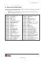
1
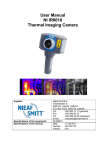
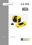
IPU 40108 issue 4 IRISYS Multi-Purpose Thermal Imagers IRI 4000 Series User Manual Safety Warning: The equipment described in this document uses a Class 2 laser. Under no account should anyone look directly into the laser beam or the laser beam exit aperture, irreversible damage to the eye may occur. The laser should not be operated when there are personnel in the imager’s field of view. Caution – use of controls or adjustments or performance of procedures other than those specified in this document may result in hazardous laser radiation exposure. InfraRed Integrated Systems Ltd Park Circle, Tithe Barn Way Swan Valley Northampton NN4 9BG Tel: (01604) 594 200 Fax: (01604) 594 210 Email: [email protected] 2009 InfraRed Integrated Systems Ltd. No part of this publication may be reproduced without prior permission in writing from Infrared Integrated Systems Ltd. This document gives only a general description of the products and except where expressly provided shall form no part of any contract. From time to time changes may be made in the products. Page 1 of 37 IPU 40108 issue 4 Contents: 1 INTRODUCTION..................................................................................................................................... 3 2 GETTING STARTED............................................................................................................................... 3 2.1 UNPACKING............................................................................................................................................. 3 2.2 POWERING THE IRI 4000 SERIES ....................................................................................................... 4 2.2.1 Using Battery Power – Inserting the Battery................................................................. 4 2.2.2 Using AC Mains Power ............................................................................................................ 5 2.2.3 Battery Charging....................................................................................................................... 5 3 OPERATING THE IRI 4000 SERIES THERMAL IMAGER................................................... 6 3.1 HARDWARE ............................................................................................................................................. 6 3.2 SWITCHING ON THE IRI 4000 SERIES ................................................................................................ 6 3.3 INFORMATION SPLASH SCREEN ............................................................................................................ 7 3.4 USING THE IRI 4000 SERIES THERMAL IMAGER ............................................................................... 7 3.4.1 Focusing ....................................................................................................................................... 7 3.4.2 Screen Display Items .............................................................................................................. 8 3.4.3 Buttons ......................................................................................................................................... 8 3.4.4 IRI 4000 series Hot Button Operation.............................................................................. 9 3.4.4.1 3.4.4.2 3.4.4.3 3.4.4.4 3.4.5 3.4.6 3.4.7 Hot Hot Hot Hot Button Button Button Button 1 2 3 4 – Zoom .................................................................................................................... 10 – Freeze/Save ....................................................................................................... 10 - Direction Buttons Control.............................................................................. 10 – Auto / Manual.................................................................................................... 10 Directional Buttons................................................................................................................. 10 Image Adjustment ................................................................................................................. 11 Menu Operation and Functions.......................................................................................... 12 3.4.7.1 3.4.7.2 3.4.7.3 3.4.7.4 3.4.7.5 Measurement Settings.................................................................................................................. 13 Camera Settings ............................................................................................................................. 13 Image Browser Menu .................................................................................................................... 14 Clock/Calendar Settings............................................................................................................... 14 Language ........................................................................................................................................... 14 3.4.8 Using the Laser Pointer ........................................................................................................ 14 3.4.9 Selecting high temperature options on the IRI4030/IRI 4035 ............................. 14 3.4.10 Advanced User Functions ................................................................................................ 16 3.5 TECHNICAL............................................................................................................................................ 18 3.5.1 Field Of View............................................................................................................................. 18 3.5.2 Persistent Settings ................................................................................................................. 19 4 THERMAL IMAGE TRANSFER FROM IRI 4000 SERIES TO A PC................................ 20 4.1 4.2 5 SD CARD .............................................................................................................................................. 20 USB CABLE .......................................................................................................................................... 20 USING THE IRI 4000 SERIES THERMAL IMAGER WITH A PC................................... 21 5.1 PC REQUIREMENTS .............................................................................................................................. 21 5.2 INSTALLATION OF SOFTWARE ONTO PC............................................................................................. 21 5.3 OPERATING “IRISYS 4000 SERIES IMAGER” PC SOFTWARE ....................................................... 21 5.3.1 Menus and Toolbar................................................................................................................. 22 5.3.1.1 5.3.1.2 Menus.................................................................................................................................................. 22 Toolbar ............................................................................................................................................... 35 6 EMISSIVITY LOOKUP TABLE ........................................................................................................ 36 7 CUSTOMER FEEDBACK ..................................................................................................................... 37 Page 2 of 37 IPU 40108 issue 4 1 Introduction This user manual describes the operation of the IRI 4000 series multi-purpose infrared thermal imager and its associated software and accessories. IRI 4000 Series Range PART NUMBER IRI 4010 IRI 4030 IRI 4035 IRI 4040 Field of View 20° X 15° 20° X 15° 20° X 15° 10.2° X 7.7° Temperature Range -10°C to + 250°C -20°C to + 250°C; 200°C to 900°C -20°C to + 250°C; 200°C to 500°C -10°C to + 250°C 2 Getting Started 2.1 Unpacking After unpacking the carrying case, you will find the standard items as shown in Figure 1. The IRI 4040 also includes a light shade. The IRI 4030/IRI 4035 versions also include a high temperature filter. USB SD Card Reader Carrying Case 12V Power Supply Rechargeable Battery Regional Mains Adapters IRI 4000 series Thermal Imager Lens Cap CD-Rom Lanyard 128 MB (min.) SD Card (inside) USB Cable for Connection to a PC Figure 1: Contents of the IRI 4000 series Multi-Purpose Thermal Imager Inspect all the items. If any item is damaged or missing, please notify your dealer immediately. Page 3 of 37 IPU 40108 issue 4 2.2 Powering the IRI 4000 series The IRI 4000 series thermal imager operates with a rechargeable battery, or from AC mains power. 2.2.1 Using Battery Power – Inserting the Battery 1. Open up the battery compartment on the bottom of the thermal imager by sliding the battery cover off as indicated in Figure 2. 2. Insert the rechargeable battery as shown below. 3. Replace the battery cover. 4. The above method also applies to replacing the battery, but make sure the imager is switched off before removing the battery. Remove Battery Cover Insert Battery Replace Battery Cover Figure 2: Inserting the Rechargeable Battery. NOTES: • The rechargeable battery will power the thermal imager for approximately 6 hours. • The battery indicator appears on the screen when the imager is switched on. It has the following four stages. 6 hours 4 hours 2 hours 1 hour Figure 3: Battery Indicator Levels. CAUTION: If the IRI 4000 series’ battery indicator flashes, the battery power is running low and it needs to be charged or replaced within 10 minutes. Page 4 of 37 IPU 40108 issue 4 2.2.2 Using AC Mains Power 1. Make sure the thermal imager is turned off. 2. Connect the provided 12V power supply into the socket on the side of the IRI 4000 series imager; see Figure 4. 3. Attach the appropriate supplied regional adapter to the power supply. 4. Plug the power supply into a mains socket. 5. Switch on the thermal imager. CAUTION: When using AC mains, use only the power supply included with the imager. Using other power supplies may damage the Thermal Imager. NOTE: • The mains power supply included with the IRI 4000 series is for powering the IRI 4000 series imagers; it will also recharge the battery (see Section 2.2.3). 2.2.3 Battery Charging • The IRI 4000 series’ battery can be charged in the imager by inserting the included 12V power supply into the DC socket under the cover on the side of the IRI 4000 series imager; see Figure 4. It takes approximately 4 hours to fully charge a fully depleted battery if the imager is switched off. Charging the battery with the imager switched on takes longer. DC Socket Figure 4: Connecting the Mains AC Power Supply Page 5 of 37 IPU 40108 issue 4 3 Operating the IRI 4000 series Thermal Imager 3.1 Hardware The IRI 4000 series system is designed for use as a handheld thermal imager. Thermal images stored on the supplied memory card can be transferred to a PC or laptop computer using the supplied memory card reader. PC software is supplied for viewing and analysis of saved thermal images. Power Button Laser Pointer Aperture Lens Laser Pointer Button Slots (see Figure 4) Battery Compartment Lens Cap Figure 5: The IRI 4000 series Hardware. Safety notice: The laser used in this device is designated Class 2. Under no circumstances should personnel look straight into the laser. 3.2 Switching on the IRI 4000 series • The imager features an On/Off power button above the display. It is switched on and off by holding the power button down for more than one second. • The IRI 4000 series takes approximately twenty seconds to become operational. During this time a number of audible clicks will be heard. This is normal as it is part of the calibration procedure. After start-up these clicks continue, but become much less frequent. • For best measurement results the imager should be switched on at least 5 minutes before use. Figure 6: Switching on the IRI 4000 series Page 6 of 37 IPU 40108 issue 4 3.3 Information Splash Screen The splash screen appears for approximately 20 seconds when the imager is switched on. It displays the time and date so the user can check that any images saved will be recorded with the correct time and date. The time and date must be manually set (see Section 3.4.7.4). Figure 7: Splash Screen Warning. Please be aware if a Thermal Imaging Camera is taken from one ambient environment into a different ambient environment, the camera must be allowed time to reach the temperature of the new ambient environment. 30 minutes is suggested. This is so the camera can give a more accurate temperature reading & will not suffer from Thermal shock. 3.4 Using the IRI 4000 series Thermal Imager 3.4.1 Focusing If the imager is not focused, the image quality will be poor and temperature measurements will not be accurate. Rotating the lens in a clockwise direction (from front view) focuses the imager at longer distances up to infinity. Rotating the lens in the opposite direction focuses the imager at shorter distances down to a minimum of 30 cm. Rotate the lens until the image has the best definition, and has the sharpest contrast at object edges. Focused 54°C measured. Not focused 46°C measured. Figure 8: Focusing . Page 7 of 37 IPU 40108 issue 4 3.4.2 Screen Display Items Battery life indicator. Scene emissivity Temperature units (˚C). and The shaped temperature measurement cursors (called SP+ and SPX) and their temperature measurement values, and their temperature difference value (∆). Temperature scale with the maximum and minimum values of the span. The centre green circle to which the laser pointer is aligned at a distance of 3m. Four hot button labels. Figure 9: Screen Display Items CAUTION: The calibrated temperature output is the figure adjacent to the cursor identifier; the temperature scale and display colours are indicators only. 3.4.3 Buttons Operation of the IRISYS 4000 series imager application is by means of the 4 hot buttons; the 4 directional buttons, the menu button and the laser button (see Figure 10). • The hot buttons are mainly used to give quick control of: 1. 2. 3. 4. zoom function, image capture, measurement cursor selection auto/manual modes. It should be noted that the hot button functions change in different modes of operation. See Section 3.4.4 for more information. • The directional buttons are used to: 1. move the position of the measurement cursors, 2. adjust the level, span, brightness and contrast, 3. navigate around the menus. See Section 3.4.5 for more information about the directional buttons; Section 3.4.6 for definitions of level and span, and Section 3.4.10 for definitions of brightness and contrast. • The menu button opens the menus. See Section 3.4.7 for more information. Page 8 of 37 IPU 40108 issue 4 • The laser button must be held down to turn the laser on. See Section 3.4.8 for more information. Power Button Hot Buttons Directional Directional Buttons Laser Button Menu Button Figure 10: Buttons 3.4.4 IRI 4000 series Hot Button Operation This section describes some of the basic functions of the IRI 4000 series. Its hot buttons are labelled 1 to 4 from left to right for the purposes of this user manual. Their function is displayed as hot button labels on the display. Their labels can change in different modes of operation. 2 1 3 Figure 11: Hot Buttons Page 9 of 37 4 IPU 40108 issue 4 3.4.4.1 Hot Button 1 – Zoom This hot button toggles the zoom feature between off (X1) and on (X2). When zoom X2 is selected the central region of the thermal image expands to fill the display as in Figure 12, and the hot button label displays “X2”. X1 X2 Figure 12: Zoom Function 3.4.4.2 Hot Button 2 – Freeze/Save Hot button 2 freezes the live thermal image. It is possible to edit the image in freeze mode before saving it. Pressing hot button 2 again saves the image as an image iri file to the SD card, whilst pressing hot button 1 instead rejects the image. The file saving takes a few seconds, and the file name is given a sequential number. See Section 5.3.1.1.4 for how to save an image direct to a PC via the USB cable. 3.4.4.3 Hot Button 3 - Direction Buttons Control. Hot button 3 selects either of the temperature measurement cursors (SP+ or SPX), or either L-S (temperature level and span) when in manual mode or B-C (thermal image brightness & contrast) when in auto mode. The 4 direction buttons are then used to adjust the position of the selected cursor, the level & span, or the brightness & contrast depending on which mode is selected. Note that SPX must be enabled in the Measurement Settings menu, and that the B-C control is an advanced user function that must be enabled before use in the Camera Settings menu. 3.4.4.4 Hot Button 4 – Auto / Manual This hot button toggles between auto and manual mode. In auto mode, the imager continually adjusts the level and span to achieve the optimum image. In manual mode it is possible to manually control the level and span to produce the image to your requirements. See Section 3.4.6 for definitions of level and span, and Section 3.4.10 for definitions of brightness and contrast. The preset brightness and contrast of the auto mode can be adjusted to suit your preferences (See Section 3.4.10). 3.4.5 Directional Buttons The directional buttons (up, down. left & right – see Figure 13) are used for three different functions. 1. If hot button 3 is set to either SP+ or SPX, the directional buttons control the position of the selected temperature cursor. (Selection displayed above hot button 3). 2. If hot button 3 is set to L-S, “up” and “down” control the manual mode’s image temperature level, and “left” and “right” control the temperature span. See Section 3.4.6 for details. If hot button 3 is set to B-C, “up” and “down” control the auto mode’s target image thermal brightness, and “left” and “right” control the target thermal contrast. See Section 3.4.10 for details. Page 10 of 37 IPU 40108 issue 4 3. If the menu is displayed, the directional buttons control the movement of the highlighted cursor and adjustment of the highlighted option (see Section 3.4.7). Up Right Left Down Figure 13: Directional Buttons 3.4.6 Image Adjustment Level and Span Definitions When hot button 4 is set to manual the IRI 4000 series’ image settings can be manually controlled by adjusting the level and span. When hot button 3 shows L-S, the “right” and “left” buttons respectively will increase and decrease the span of the image (4˚C in the example in Figure 14). The “up” and “down” buttons will increase and decrease the thermal level of the image (29˚C in the example in Figure 14). Level = (Max + Min)/2 = 29˚C Span = Max – Min = 4˚C Figure 14: Level and Span The IRI 4000 series’ image settings are fully automatic when hot button 4 is set to auto. The auto mode automatically adjusts the level and span to display a presentable image. Page 11 of 37 IPU 40108 issue 4 3.4.7 Menu Operation and Functions The main menu structure is opened by pressing the menu button in the centre of the directional buttons. Figure 15: Menu Button There are four sub-menus, which contain the functions listed in Table 1. Measurement Settings Camera Settings Image Browser Clock/ Calendar Language Emissivity Reflected Temperature Spot X Colour Palette Auto Power View Delete Year Month English French Day German Hour Minute Date Format Time Format Italian Spanish Temperature Units Area Hot / Cold Factory Settings Image Only B-C Cursor Reset Table 1: Menu Functions The menu functions are selected by moving the highlighted cursor using the up and down directional buttons. Menu items are edited using hot buttons 2 & 3 which are labelled + and -. Hot button 1 is always available to take you “back” one menu sub-level, whilst hot button 4 is always available to “exit” the menus completely. Figure 16 shows an example screenshot from the Measurement Settings menu, with the highlighted cursor on the emissivity adjustor. Figure 16: Menu Operation Page 12 of 37 IPU 40108 issue 4 3.4.7.1 Measurement Settings • Emissivity – The user can select the emissivity for the material being imaged. To achieve correct temperature measurement the emissivity value must be set correctly. An emissivity lookup table is included in Section 6. NOTE: Caution should be observed in using the emissivity control – the user should explore the effect on the observed temperature of an object when different emissivities are selected. Low values of emissivity should be used only with extreme caution as large errors in temperature readings may be obtained with only small errors in emissivity. Care should also be taken to avoid reflections from hot/cold objects in the vicinity. • Reflected T – When the emissivity is set to values less than 1.0, measurement accuracy can be further improved by setting the reflected temperature compensation. The reflected temperature is the temperature being “seen” by the object being imaged. The value entered must be within the range -20ºC to 200ºC or equivalent in ˚F or K. • Spot X - Toggle the second temperature cursor (SPX) display on/off the screen. When SPX is displayed the temperature difference (∆) between SP+ and SPX is also displayed. • Area – This removes the temperature measurement cursors from the image, and instead displays a small rectangle in the centre of the image. The cursor measurement readout changes to display the maximum and the minimum temperature within the rectangle. When a saved image is browsed in area analysis mode, the average temperature for the rectangle ( ¯ x ) is also displayed. • Hot/Cold – The measurement cursor SP+ automatically tracks the hottest pixel in the image. If the SPX measurement cursor is selected, SPX automatically tracks the coldest pixel in the image. • Temperature Units – Select between degrees Celsius, degrees Fahrenheit and Kelvin. 3.4.7.2 Camera Settings • Colour Palette – The user can select one of four possible colour options. They are Rainbow, Ironbow, Greyscale (monochrome) or HC Rainbow (high contrast). • Auto Power – Turns the imager off if it has been left on without a button press for 20 minutes. • Factory Settings – For the convenience of the user, many settings are persistent, i.e. the settings and values are remembered when the IRI 4000 series is switched off. Selecting the factory settings function restores the imager to its factory default settings. • Image only - This option displays the image and the hot button labels only. Page 13 of 37 IPU 40108 issue 4 • Brightness & Contrast – This option selects whether the advanced user function of brightness and contrast control is available on hotkey 3 when in auto mode (see Section 3.4.10). • Cursor Reset – Select this option to restore the cursor (or 2 cursors) to their default positions. 3.4.7.3 Image Browser Menu • This browser shows a list of file numbers found on the SD memory card, starting with the most recent image. It is possible to scroll through the list and choose to view images or to delete image files. 3.4.7.4 Clock/Calendar Settings • Set Clock – The clock can be set so images are saved with the time and date of image capture. • Date Format – choose between dd/mm/yy or mm/dd/yy. • Time Format – 12 Hour / 24 Hour clock 3.4.7.5 Language • English, French, German Italian, Spanish 3.4.8 Using the Laser Pointer When the IRI 4000 series is switched ‘ON’, the laser may be activated by pressing and holding down the red laser button. Laser Button The laser pointer is used to illuminate and identify features in the image. The laser pointer illuminates the area of the scene that coincides with the green circle indicator on the display – see Figure 9. NOTE: The laser is aligned to objects at a distance of 3m from the front of the imager. Figure 17: Laser Pointer 3.4.9 Selecting high temperature options on the IRI4030/IRI4035 The IRI 4030 and IRI 4035 versions are supplied with a detachable filter. Adding the filter, and selecting high temperature mode, allows the imager to operate on higher scene temperatures. With Filter Without Filter IRI 4030 +200°C to +900°C -20°C to +250°C IRI 4035 +200°C to +500° -20°C to +250°C To select the extended temperature range on the imager:(i) Fit the filter as described in section a) below and (ii) select the correct calibration setting as described in section b) below. Page 14 of 37 IPU 40108 issue 4 a) Screw the filter onto the imager lens as shown in figures 18 to 21 below. Figure 18 Imager without filter Figure 20 Filter being screwed into place Figure 19 Filter being fitted Figure 21 Filter fitted b). Selecting the correct calibration settings. Figure 22 1) Press the menu button to select menus. 2) Select camera settings. 3) Select high temperature option. 3.1) On -selects the high temperature option. When this is selected a “T” appears on the status line. 3.2) Off -selects the standard temperature option. When this is selected the “T” disappears from the status line. Figure 23 High Temperature on. Figure 24 High temperature off Selecting the standard temperature range option. Reverse the above. (i) Press the menu button to enter menus. (ii) Select camera settings. (iii) Select high temperature and select “off”. (iv) Unscrew the filter. Page 15 of 37 IPU 40108 issue 4 3.4.10 Advanced User Functions Brightness & Contrast Definitions The thermal brightness is the colour at the centre of the colour scale, (the default thermal brightness for the rainbow colour palette is a yellow/green colour see Figure 25). Note that the brightness of the image does not refer to the brightness of the screen. For a greyscale image, brighter means whiter, and for a rainbow image, yellow is brighter than blue, and red is brighter than yellow. The contrast is the amount of the colour bar that the image uses, and it uses the whole colour bar by default. Brightness = (Centre of colour bar) = Yellow/Green by default Contrast = (Amount of colour bar) = Whole colour bar by default Figure 25: Brightness & Contrast Definitions The target thermal brightness and contrast of the auto mode can be manually set when B – C is toggled to “ON” in the camera settings menu. This enables hot button 3 to be toggled to B-C when the imager is in auto mode. In this case the “right” and “left” buttons will increase and decrease the contrast of the image. The “up” and “down” buttons will increase and decrease the thermal brightness of the image. Page 16 of 37 IPU 40108 issue 4 Edit the Contrast Edit the Brightness Default contrast Default brightness Increasing the contrast uses more of the outer colours of the colour palette i.e. black and white in the rainbow example. Increasing the thermal brightness uses more of the upper half of the colour bar. Reducing the contrast uses less of the outer colours of the colour palette, and uses more of the central colours i.e. green and yellow in the rainbow example. Decreasing the thermal brightness uses more of the lower half. See the examples in Figure 25 for more information. Figure 26: These 6 figures show the effect of increasing and decreasing the auto mode’s brightness and contrast. The practical advantage of this is that the user can completely control the appearance of the image without having to adjust the level and span manually when viewing different scene temperatures. NOTE: The brightness and contrast can be reset back to the defaults by pressing hot button 4 to manual mode, and then hot button 4 again back to auto mode. Page 17 of 37 IPU 40108 issue 4 3.5 Technical 3.5.1 Field Of View IMAGER IRI 4010 IRI 4035 IRI 4030 IRI 4040 Field of View 20˚ x 15˚ 20˚ x 15˚ 20˚ x 15˚ 10.2˚ X 7.7˚ Detector Size 160 x 120 160 x 120 160 x 120 160 x 120 The IRI 4010/IRI4030/IRI 4035 have a 20˚ x 15˚ Field of View lens whilst the IRI 4040 has a 10.2˚ X 7.7˚ field of view lens. All of the IRI 4000 series has a 160 x 120 (19200) pixel detector. Figure 27: Field of View 120 pixels 160 pixels Figure 28: 19200 Pixel Array Page 18 of 37 IPU 40108 issue 4 3.5.2 Persistent Settings 3.5.2.1. The following table shows which settings are persistent after the Imager is switched off. Persistent Setting Cursors Emissivity Reflected temperature Temperature Units Area Hot/Cold Tracking Colour palette Auto Power Image Only B–C Time & Date Date format Time Format Language High Temperature selection Only for the IRI 403 & IRI 4035 * 3.5.2.2. The following table shows the setting values when you perform a “camera reset”. Setting Emissivity Reflected temperature Cursors Temperature Units Area Hot/Cold Tracking Colour palette Auto Power Image Only B–C Time & Date Date format Time Format Language Reset to: 1.00 25°C One C Off Off Ironbow Never Off Off DD/MM/YY 24 Hour English Page 19 of 37 IPU 40108 issue 4 4 Thermal Image Transfer from IRI 4000 series to a PC 4.1 SD Card The Secure Digital (SD) memory card is the IRI 4000 series’s storage device for thermal images. This is also used to transfer thermal images to a PC when used with the SD card reader. Note that the imager will not be able to save thermal images without the SD card installed. 1. Save thermal images onto the SD card as described in Section 3.4.4.2. 2. Remove the SD card. 3. Slot the SD card into the SD/MMC slot on the USB SD card reader supplied, making sure of the correct orientation. Figure 29: Inserting the SD card. 4. Insert the USB connector of the SD card reader into a USB port on the PC, using the extender USB cable if required. 5. Follow the card reader’s installation instructions if prompted by Windows. 6. Either open My Computer and copy the .iri files from the SD card to the PC (recommended), or leave the SD card in place whilst the “IRISYS 4000 Series Imager” PC software is running and open the files directly from the SD card. NOTE: Image files must retain their file name (TIXXXXXX.iri). If they are renamed on the PC, they will no longer be readable by the imager. Warning, If the Imager SD memory card is removed from the imager and reformatted using a laptop, PC or other device, the SD memory card will take on the format of that device. When the SD memory card is then returned to the imager the SD memory card will not be readable by the imager and the message “No MMC/SD card” will appear. The SD memory card MUST be reformatted with its original file format (either FAT or FAT16) 4.2 USB Cable A live thermal image can be saved directly to a PC using the USB cable provided connected between a PC’s USB port, and the imager’s USB socket (see Figure 30). The “IRISYS 4000 Series Imager” PC software must be installed onto the PC before making this connection. See Section 5.3 for more information. USB Socket, for connecting to a PC Figure 30: Slots and Sockets Page 20 of 37 IPU 40108 issue 4 5 Using the IRI 4000 series Thermal Imager with a PC 5.1 PC Requirements The PC should be IBM compatible running Microsoft Windows - XP, 2000 or VISTA(32bit);. with a CD drive, and a USB port or an SD card reader. The “IRISYS 4000 Series Imager” application can be used for analysis of images previously saved onto an IRI 4000 series SD card, or for downloading a live thermal image from the IRI 4000 series via a USB cable. NOTE:- With the VISTA operating system, the IRI files cannot be previewed in windows explorer, however when opening the PC software it will create bitmaps allowing subsequent previews in windows explorer 5.2 Installation of Software onto PC The software is supplied on a mini CD-Rom. 1. 2. 3. 4. Insert the supplied mini CD-Rom into the PC’s CD-Drive. Double click on ‘My Computer’ and then on the CD-Drive. Double click on ‘4000 PC Setup.exe’. Follow the on screen prompts to complete the installation. NOTE: • The IRISYS 4000 Series Imager software will by default be installed into the following path: C:\Program Files\IRISYS\IRISYS 4000 Series Imager • The above path and name can be changed during the installation, but it is advisable to leave it as the default. The installation will also put a ‘Shortcut Icon’ onto your PC’s desktop to allow quick and easy start-up of the software. 5.3 Operating “IRISYS 4000 Series Imager” PC Software Launch the IRISYS 4000 Series Imager program from the Desktop icon, Figure 31: Desktop Icon Figure 32: .Iri File Icon or from: START/PROGRAMS/IRISYS/IRISYS 4000 Series Imager Alternatively it is possible to run the program by using Windows Explorer to find .iri files on your PC and then double-clicking an .iri file icon. ( see fig 32 above) Page 21 of 37 IPU 40108 issue 4 The application executes and it looks like Figure 33, with the options window visible, and with empty frames for the image, colour bar and thermal histogram. The application window includes the file name if the file has been saved; otherwise it reads “Untitled”. Figure 33: Application Window 5.3.1 Menus and Toolbar The menu includes familiar Windows menu items such as “File”, “Edit”, “View”, Tools” and “Help”. Figure 34: The Menu 5.3.1.1 Menus 5.3.1.1.1 File The File menu contains the following features: • Open • Save • Save As… • Revert • Excel Output… • Recent Files • Exit Page 22 of 37 IPU 40108 issue 4 1) Open - Uses Windows Explorer (see Figure 35) to open an iri file from your computer. Figure 35: Windows Explorer The iri files can be previewed in any of the five Windows explorer views: thumbnail, tile, icon, list or details, by selecting the “View” button in Windows explorer (shown in Figure 35 and Figure 36). Figure 36: View Selector After an image has been opened, the application window looks similar to Figure 37 below. The four main components of the application window are the options window, the image, the colour bar and the thermal histogram. Overlaid on the histogram is the movable span selector which adjusts the level and span of the thermal image. The span selector can be moved by clicking in the middle of the histogram and dragging left or right. The span can be increased and decreased by clicking towards the ends of the span selector (where the max and min values of the span are displayed) and dragging left or right. The span can be automatically reset by double-clicking in the middle of the span selector. Page 23 of 37 IPU 40108 issue 4 Colour Bar Options Window Image Thermal Histogram Figure 37: Application Window 2) Save – saves the iri file with the same name it had previously. If it was previously unsaved, the Save As… window appears. 3) Save As… – images are saved using a similar window to the “Open” window in Figure 35, but a file name must be entered. 4) Revert – restores an image file back to its last saved state. 5) Excel Output… - save a 160 x 120 array of temperature data (assuming emissivity = 1) in comma separated variable format for use with Microsoft Excel and other spreadsheet applications. 6) Recent Files – a list of recently opened iri files appears here for easy selection. 7) Exit – closes the IRISYS 4000 Series Imager application. 5.3.1.1.2 Edit The Edit menu contains the following features: • Copy • Copy to Bitmap 1) Copy - This copies a screen capture of the application window or the thermal image into the Windows clipboard. This picture can then be pasted into a picture editor or Microsoft office document. 2) Copy to Bitmap – This saves a screen capture of the application window or the thermal image as a bitmap image using a dialogue box similar to Figure 35 above. Page 24 of 37 IPU 40108 issue 4 5.3.1.1.3 View The View menu enables the following features, most of which are also available on the toolbar: • Toolbar • Status Bar • Measurement Cursor List • Measurement Cursors • Hot & Cold Cursors • Area Select • Blue Isotherm • Red Isotherm • Profiles • Options 1) Toolbar – This toggles the display of the icon toolbar below. Figure 38: Toolbar 2) Status Bar – This toggles the display of the status bar, which includes the temperature value and pixel position of the pixel under the mouse cursor when the mouse is over the image. It also displays the difference between the midpoints of the isotherms if both the isotherms are enabled. Figure 39: Status Bar 3). Measurement Cursor List - This toggles the display of the measurement cursors list shown in Figure 40, which includes the spot measurement, pixel position, and the difference between measurement cursors 1 and 2. It also displays the hottest and coldest measurements in the scene, their difference, and the average temperature for the image. Also shown are the maximum, minimum and average temperatures for the area analysis box (if selected in the view menu). Page 25 of 37 IPU 40108 issue 4 Figure 40: Measurement Cursor List Measurement cursors are added to the image by double-clicking in the location that the cursor is required. When the mouse cursor is moved over a measurement cursor the mouse cursor appears as a hand. When this happens the measurement cursors can be moved around by dragging them, and can be removed by double clicking them. Measurement Cursors – This toggles the display of the measurement cursors on 4) the thermal image. This does not delete the cursors; it temporarily hides them. Figure 41: A Measurement Cursor Hot & Cold Spot Cursors – This toggles cursors over the hottest and coldest 5) measurements in the thermal image. The values of these (and the difference) are shown in the measurement cursors list. Figure 42: Hotspot Cursor 6) Area Select – This toggles a rectangular area over the centre of the image. The maximum, minimum and average temperatures for this area are then displayed in the measurement cursors list, allowing measurement by area analysis. Page 26 of 37 IPU 40108 issue 4 The area’s position can be moved in conjunction with the zoom & pan control (see Figure 43). For more information on the zoom & pan control see Figure 47. Figure 43: Area Select 7 & 8) Isotherms – This toggles the two isotherms which can be used to highlight areas of the same temperature in the image. A red and/or blue semi transparent block appears on the histogram which can be moved and adjusted in the same way as the image span selector. Every object in the image with a temperature within the range of the isotherms appears either red or blue in the image. Use of the greyscale colour palette is recommended whilst using the isotherms. Figure 44: Dual Isotherms Page 27 of 37 IPU 40108 issue 4 9) Profiles – This toggles the 2D profile view which is used to display a graphical representation of the temperature values along the selected vertical and horizontal lines. Intensity Plot Lines Cross Sections Thermal Intensity Plots Figure 45: 2D Profiles To the left of the image is a thermal intensity plot which corresponds to the vertical cross section through the image. Below the image is a similar plot that corresponds to the horizontal cross section. The cross sections can be moved by dragging them either independently or by dragging the intersection. The short green intensity plot lines on the thermal intensity plots can be moved to analyse temperatures in the plots. Double-click an intensity plot line to make the corresponding cross section line-up with it. 10) Options – This toggles the display of the options window. The options window has four tabs across the top and it can be embedded in the application window or in a free-floating window, depending on whether or not “Dock Options” is ticked in the “Tools” menu. Click the tab labels to select each tab. Figure 46: Options Tab Labels Page 28 of 37 IPU 40108 issue 4 The Display tab is shown below: Figure 47: Display Tab In the Display tab, it is possible to: • • • • • • Adjust the span of the image manually (by typing) Adjust the span of the image automatically Select one of four colour palettes Select whether to display the image at its original resolution or to interpolate the image to 320 x 240 or 640 x 480 Select zoom factor from x1 to x4 Select which area of the image to zoom by dragging the green box in the pan control using a mouse The Cursors tab is shown below: Figure 48: Cursors Tab Page 29 of 37 IPU 40108 issue 4 In the Cursors tab, it is possible to: View the temperature values of the measurement cursors, and also their pixel numbers from the origin (bottom left of image) and the emissivity value associated with the cursors. • Delete cursors from the image by selecting them in the “name” column and clicking “remove”. Multiple cursors can be removed simultaneously by using the standard Windows selection methods with the Ctrl or Shift buttons. The Settings tab is shown below: • Figure 49: Settings Tab In the Settings tab, it is possible to: • • • • • Select ˚C, ˚F or K Adjust the reflected temperature correction Adjust the target object emissivity Adjust the required capture time and date Add comments to the image Page 30 of 37 IPU 40108 issue 4 The Properties tab is shown below: Figure 50: Properties Tab This tab displays important file information. Sequence Tab The Sequencing feature allows the user to capture a number of thermal images from the imager and directly save them on to a PC. The user can:(a) Adjust the time delay between the capture of the images. (b) Define the total period over which images are captured. (c) Select the start and stop times of the image capture process. (d) Define the total number of images to be captured. (e) Manually control the capture process. 1. Items required:1.1. 1 x IRI4010 Thermal imaging camera. 1.2. 1 x USB cable. 1.3. 1 x PC with Irisys imager software installed. 2. Set up instructions:2.1. Using the USB cable connect the PC to the thermal imaging camera. 2.2. Power up the imager after the PC. 2.3. Click on the 4000 series imager icon. Page 31 of 37 IPU 40108 issue 4 3.1. Sequence recording setup. 3.1.1. Select the sequence tab. 3.1.2. Click on the change button to bring up the Image Comms Config window. 3.1.3. Click on a port to highlight it and then press the test port button. 3.1.4. If the box turns green and the message “USB Serial Port com (number) – ok” appears. The comms port connection is correctly made. Click on OK to continue. 3.1.5. If the box turns red and the message “USB serial port (COM) – ERROR” appears, the comms port connection is not the right one. Try the other ports in the available ports options; click on test port until the box turns green.. Click on OK to continue. Page 32 of 37 IPU 40108 issue 4 3.2.. Image capture setup. 3.2.1. Set the Capture Delay in minutes and second . using the arrow buttons. This is the time delay between captured snapshot images. In the example shown this is 10 seconds. 3.2.2. For capturing images over a specific Capture Period. Enter the required period in hrs, minutes and seconds. For example in this case 10 minutes. Please also remember to tick the Capture Period H:M:S box. 3.2.3. For capturing images over a specific period of time, enter Start and Stop Times. In this example from 11.05 am to 11.10am. Please also remember to tick the Start and Stop time boxes. 3.2.5. To capture a specific number of images tick the Limit Images box and inserting the number of images required. For example, in this case 10 images. 3.2.6. For total manual control do not tick any of the above (3.3.2. to 3.4.but press the Start button when ready. The button will then change to Stop. 3.3. Saving images. Setting the snapshot folder. It is important to select which location the captured image snapshots should be saved too. For example in this case C:\Documents and Settings\Desktop. Please also remember to tick the Save Images box. 3.4.. If the start/stop button is not visible, the screen will have to maximised. The number of images captured will depend on the sequence selected. If a combination is selected, the least number of images will be saved. If no sequence is selected then Capturing will continue until the stop button is clicked. 5.3.1.1.4 Tools The Tools menu contains the following: • Imager Comms Config… • Capture From Imager… • Reset Isotherms • Dock Options… 1) Imager Comms Config… - This is used to transfer single images taken from the live image in the IRI 4000 series to a PC via a USB connection. The first time the imager is connected to a PC via USB, the USB drivers must be installed to the PC from the CD. Page 33 of 37 IPU 40108 issue 4 1. 2. 3. 4. 5. Switch imager on connect USB cable to imager connect USB cable to PC the Windows “found new hardware wizard” will appear direct the wizard to the “USB Virtual Com Port” folder on the CD, and click “next” You may have to repeat parts 4 and 5 to install the second part of the 2-part USB driver. Once the drivers have been installed, select Imager Comms Config to open the window in Figure 51 below. Select the “USB Serial Port (COM X)” from the list, click “Test Port” and then click “OK”. Figure 51: Port Selection Capture from imager… - After setting up the Imager Comms Config, select this to 2) take a new image from the imager. The IRI 4000 series imager must be switched on and connected via the USB cable provided to a USB port on your computer. The file transfer takes approximately 10 seconds. As always when taking an image, make sure the imager is correctly focused on the target. 3) Reset Isotherms – This moves the two isotherms back to their default positions. The isotherms must be displayed to see the effect of this tool. 4) Dock Options – This selects whether to dock the Options dialog box into the application window or whether to have the Options in a free-floating window of its own. If the Options box is not displayed, this menu item will be disabled. Figure 52: Options Docked and Free-Floating Page 34 of 37 IPU 40108 issue 4 5.3.1.1.5 Help The Help menu gives the following information: • About 1) About IRISYS 4000 Series Imager – This displays the IRISYS software version being used. Figure 53: Version Information 5.3.1.2 Toolbar The Toolbar includes 12 icons; all of which have been covered in the menus. The icons are listed below. Figure 54: Toolbar 1) Open 2) Save 3) Capture from Imager 4) View Options 5) Toggle Measurement Cursor list 6) Toggle Measurement Cursors 7) Toggle Hot & Cold Cursors 8) Toggle Area Select 9) Toggle Blue Isotherm 10) Toggle Red Isotherm 11) Toggle Profile Display 12) About - See See See See See See See See See See See See Section Section Section Section Section Section Section Section Section Section Section Section Page 35 of 37 5.3.1.1.1 5.3.1.1.1 5.3.1.1.4 5.3.1.1.3 5.3.1.1.3 5.3.1.1.3 5.3.1.1.3 5.3.1.1.3 5.3.1.1.3 5.3.1.1.3 5.3.1.1.3 5.3.1.1.3 IPU 40108 issue 4 6 Emissivity Lookup Table Below is a list of approximate emissivity values for a range of materials for making more accurate temperature measurements. NOTE: Emissivity values often vary with temperature and wavelength so this table is included as a guide only. 1.000000 0.980000 0.980000 0.980000 0.970000 0.960000 0.960000 0.950000 0.950000 0.940000 0.940000 0.930000 0.930000 0.920000 0.920000 0.910000 0.900000 0.900000 0.890000 0.880000 0.870000 0.860000 0.850000 0.850000 0.840000 0.830000 0.820000 0.810000 0.800000 = = = = = = = = = = = = = = = = = = = = = = = = = = = = = Black body Carbon filed surface Frost crystals Skin human Slate Water distilled Ice smooth Soil saturated with water Carbon candle soot Glass polished plate Paint, oil Brick red Paper white bond Concrete Soil dry Plaster rough coat Wood planed oak Glazed earthenware Snow, granular Glazed Silica Cuprous Oxide at 38°C Emery Corundum Snow Stainless oxidized at 800°C Oxidised Iron at 500°C Cuprous Oxide at 260°C Snow, fine particles Brass, unoxidised Glass, convex D 0.790000 0.780000 0.770000 0.760000 0.750000 0.740000 0.730000 0.720000 0.710000 0.700000 0.690000 0.670000 0.660000 0.650000 0.640000 0.630000 0.620000 0.610000 0.580000 0.560000 0.550000 0.210000 0.200000 0.160000 0.090000 0.070000 0.050000 0.050000 0.030000 Page 36 of 37 = = = = = = = = = = = = = = = = = = = = = = = = = = = = = Steel oxidised Copper heavily oxidised Cotton cloth Sand Unglazed silica Oxidised iron at 100°C Coating No. C20A Basalt Graphitised carbon at 500°C Red Rust Iron sheet heavily rusted Water Black Loam White cement Iron cast oxidised Lead oxidised at 1100°F Zirconia on inconel Cu-Zn, brass oxidised Inconel sheet at 760°C Smooth white marble Al anodised chromic acid Iron cast polished Brass rubbed 80 grit emery Stainless steel 18-8 buffed Aluminium as received Steel polished Aluminium polished sheet Copper polished Brass highly polished IPU 40108 issue 4 7 Customer Feedback If you have had any technical issues or feedback with regard to your IRI 4000 series Multi-Purpose Thermal Imager, please complete the details below and send it back to IRISYS at the address on the front page of this manual. Name: Company Name and address: Contact Details: IRI 4000 series Thermal Imager Serial Number: (This can be found printed under the “slots & sockets” cover) PC Software Version installed: Software version number can be found whilst software is running from: PC – Help/About IRISYS 4000 Series Imager Description of Technical Fault: All brands and product names are acknowledged and may be trademarks or registered trademarks of their respective holders. Page 37 of 37