1
USER'S MANUAL
Thank you very much for purchasing this product.
➢ To ensure correct and safe usage with a full understanding of this product's performance, please be
sure to read through this manual completely and store it in a safe location.
➢ Unauthorized copying or transferral, in whole or in part, of this manual is prohibited.
➢ The contents of this operation manual and the specifications of this product are subject to change
without notice.
➢ The operation manual and the product have been prepared and tested as much as possible. If you
find any misprint or error, please inform us.
➢ Roland DG Corp. assumes no responsibility for any direct or indirect loss or damage which may
occur through use of this product, regardless of any failure to perform on the part of this product.
➢ Roland DG Corp. assumes no responsibility for any direct or indirect loss or damage which may
occur with respect to any article made using this product.
For the USA
FEDERAL COMMUNICATIONS COMMISSION
RADIO FREQUENCY INTERFERENCE
STATEMENT
This equipment has been tested and found to comply with the
limits for a Class A digital device, pursuant to Part 15 of the FCC
Rules.
These limits are designed to provide reasonable protection
against harmful interference when the equipment is operated in
a commercial environment.
This equipment generates, uses, and can radiate radio frequency
energy and, if not installed and used in accordance with the
instruction manual, may cause harmful interference to radio
communications.
Operation of this equipment in a residential area is likely to
cause harmful interference in which case the user will be
required to correct the interference at his own expense.
Unauthorized changes or modification to this system can void
the users authority to operate this equipment.
The I/O cables between this equipment and the computing
device must be shielded.
For Canada
CLASS A
NOTICE
This Class A digital apparatus meets all requirements of the
Canadian Interference-Causing Equipment Regulations.
CLASSE A
AVIS
Cet appareil numérique de la classe A respecte toutes les
exigences du Règlement sur le matériel brouilleur du
Canada.
ROLAND DG CORPORATION
1-6-4 Shinmiyakoda, Hamamatsu-shi, Shizuoka-ken, JAPAN 431-2103
MODEL NAME
: See the MODEL given on the rating plate.
RELEVANT DIRECTIVE : EC LOW VOLTAGE DIRECTIVE (73/23/EEC)
EC ELECTROMAGNETIC COMPATIBILITY DIRECTIVE (89/336/EEC)
Contents
Read This First ....................................................................................................................................... 3
Machine Functions ........................................................................................................................................................ 3
To Ensure Safe Use ....................................................................................................................... 6
Important Notes on Handling and Use ........................................................................................... 10
Chapter 1: Setup Preparation ........................................................................................................... 11
1-1 Included Items ...................................................................................................................................................... 12
1-2 Part Names ............................................................................................................................................................ 13
Main Unit ...................................................................................................................................... 13
1-3 Installing .................................................................................................................................................................. 14
Deciding On an Installation Site ................................................................................................... 14
Installation Space .......................................................................................................................... 14
Removing the Packing Materials ................................................................................................... 15
Connecting the Cables .................................................................................................................. 16
Chapter 2: Installing Software ........................................................................................................... 17
2-1 About the Included Software ............................................................................................................................ 18
2-2 If You're Using a Windows ............................................................................................................................... 19
System Requirements .................................................................................................................... 19
Installing the Software ................................................................................................................... 20
2-3 If You're Using a Macintosh .............................................................................................................................. 23
System Requirements .................................................................................................................... 23
Installing the Software ................................................................................................................... 23
Chapter 3: Performing Cutting ......................................................................................................... 25
3-1 What to Know Before Cutting ........................................................................................................................ 26
Useable Material Types ................................................................................................................. 26
3-2 Cutting .................................................................................................................................................................... 28
Step 1: Load Material .................................................................................................................... 28
Step 2: Create Cutting Data ........................................................................................................... 30
Step 3: Perform Cutting ................................................................................................................. 34
Step 4: Apply the Cut Material ...................................................................................................... 36
Chapter 4: Mastering the STIKA ...................................................................................................... 37
4-1 Optimizing the Cutting Quality for the Material ......................................................................................... 38
Check the Cutting Quality for the Material .................................................................................... 38
Adjusting the Blade Extension Amount .......................................................................................... 39
4-2 Correcting the Angle of the Loaded Material .............................................................................................. 40
4-3 About Creating Cutting Data ........................................................................................................................... 41
Creating Various Text Data ............................................................................................................ 41
Creating Contour Data by Reading a BMP/JPG Format File ........................................................... 43
Deleting Undesired Cutting Lines .................................................................................................. 45
4-4 Applying Large Materials .................................................................................................................................... 46
1
Contents
Chapter 5: Maintenance ..................................................................................................................... 47
5-1 Maintenance .......................................................................................................................................................... 48
Cleaning the Blade Tip .................................................................................................................. 48
Cleaning the Blade Holder ............................................................................................................ 48
Cleaning the Main Unit ................................................................................................................. 48
5-2 Replacing Consumables ...................................................................................................................................... 49
Replacing the Blade ...................................................................................................................... 49
Replacing the Blade Protector ....................................................................................................... 50
Chapter 6: Appendix ........................................................................................................................... 53
6-1 What to Do If ....................................................................................................................................................... 54
The machine does not run properly .............................................................................................. 54
The cut incisions are not clean ...................................................................................................... 54
Parts of the material are not continuously cut ............................................................................... 54
The cut location is shifted forward/back ........................................................................................ 54
The cut location is shifted left/right ............................................................................................... 54
The material shifts during cutting .................................................................................................. 55
If the driver cannot be installed ..................................................................................................... 55
Uninstalling the driver ................................................................................................................... 56
6-2 Shaft Lubrication .................................................................................................................................................. 57
6-3 Cutting Range ....................................................................................................................................................... 58
6-4 Locations of the Power Rating and Serial Number Labels ........................................................................ 59
6-5 Specifications ......................................................................................................................................................... 60
CutStudio is a trademark of Roland DG Corp.
Windows® is a registered trademark of Microsoft® Corporation in the United States and/or other countries.
Macintosh and Mac OS are registered trademarks or trademarks of Apple Computer, Inc. in the USA and other countries.
Adobe and Adobe Illustrator are either registered trademarks or trademarks of Adobe Systems Incorporated in the United States and/or other countries.
Corel and CorelDRAW are registered trademarks or trademarks of Corel Corporation or Corel Corporation Limited.
Other company names and product names are trademarks or registered trademarks of their respective holders.
Copyright© 2005 Roland DG Corporation
2
http://www.rolanddg.com/
Read This First
Machine Functions
For Windows
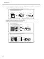
➢You can use the included cutting software "Roland CutStudio" to create stickers and stickers with images.
• CutStudio Overview, Installation Method ☞ User's Manual (this document) p 18
You can use your own designs to create original stickers.
☞ User’s Manual (this document) p 28
CutStudio
STIKA
Sticker
You can use STIKA in combination with a printer to create stickers with images.
☞ Windows Advanced Guide (electronic format)
CutStudio
Printer
STIKA
Sticker with image
➢You can use the included Adobe Illustrator software plug-in "CutStudio Plug-in for Adobe Illustrator" to send
cutting data created in Illustrator to CutStudio and create stickers and stickers with images.
• Software plug-in overview, installation method ☞ Windows Advanced Guide (electronic format)
You can make stickers with data created in Illustrator.
☞ Windows Advanced Guide (electronic format)
Illustrator
+
CutStudio
Sticker
STIKA
You can use STIKA in combination with a printer to create stickers with images.
☞ Windows Advanced Guide (electronic format)
Illustrator
+
CutStudio
Printer
STIKA
Sticker with image
3
Read This First
➢You can use the included CorelDRAW software plug-in "CutStudio Plug-in for CorelDRAW" to send data
created in CorelDRAW to CutStudio and create stickers.
• Software plug-in overview, installation method ☞ Windows Advanced Guide (electronic format)
You can create stickers with data created in CorelDRAW.
☞ Windows Advanced Guide (electronic format)
CorelDRAW
+
CutStudio
STIKA
Sticker
➢You can use the included software "STIKA Navi" to operate STIKA from your computer. Operation is simple;
just follow the instructions displayed on your computer screen.
• STIKA Navi Overview ☞ Windows Advanced Guide (electronic format)
You can run a material jam test.
☞ Windows Advanced Guide (electronic format)
STIKA Navi Operation Screen
Click
STIKA
You can cut in areas of the material that have not yet been cut.
☞ Windows Advanced Guide (electronic format)
STIKA Navi Operation Screen
Click
Unused part
4
STIKA
Read This First
For Macintosh
➢You can use the included software plug-in "CutStudio Plug-in for Adobe Illustrator" to make stickers with data
created in Illustrator.
• Software plug-in overview, installation method ☞ User's Manual (this document) p 23
You can create stickers with data created in Illustrator.
☞ Macintosh Cutting Guide (electronic format)
Illustrator
+
CutStudio
STIKA
Sticker
5
To Ensure Safe Use
Improper handling or operation of this machine may result in injury or damage to property.
Points which must be observed to prevent such injury or damage are described as follows.
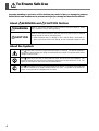
About
WARNING and
WARNING
CAUTION Notices
Used for instructions intended to alert the user to the risk of death or severe
injury should the unit be used improperly.
Used for instructions intended to alert the user to the risk of injury or material
damage should the unit be used improperly.
CAUTION
* Material damage refers to damage or other adverse effects caused with respect to the home and all its furnishings, as well to domestic animals or pets.
About the Symbols
The
symbol alerts the user to important instructions or warnings. The specific meaning of
the symbol is determined by the design contained within the triangle. The symbol at left means
"danger of electrocution."
The
symbol alerts the user to items that must never be carried out (are forbidden). The
specific thing that must not be done is indicated by the design contained within the circle. The
symbol at left means the unit must never be disassembled.
The
symbol alerts the user to things that must be carried out. The specific thing that must
be done is indicated by the design contained within the circle. The symbol at left means the
power-cord plug must be unplugged from the outlet.
6
To Ensure Safe Use
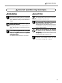
Incorrect operation may cause injury
WARNING
Keep children away from the machine.
The machine includes areas and components
that pose a hazard to children and may result in
injury, blindness, choking, or other serious accident.
Never attempt to disassemble, repair, or
modify the machine.
Doing so may result in fire, electrical shock, or
injury. Entrust repairs to a trained service technician.
For accessories (optional and consumable
items, AC adapter, power cord, and the
like), use only genuine articles compatible
with this machine.
Incompatible items may lead to an accident.
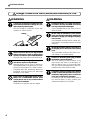
CAUTION
Caution: cutting tool.
This machine has an internal tool. To avoid injury, handle the tool with care.
Before attempting cleaning, maintenance,
or attachment or detachment of optional
items, disconnect the power cord.
Attempting such operations while the machine
is connected to a power source may result in
injury or electrical shock.
Never use the machine for any purpose
for which it is not intended, or use the
machine in an undue manner that exceeds
its capacity.
Doing so may result in injury or fire.
Install in a location that is level and stable.
Installation in an unsuitable location may cause
an accident, including a fall or tipover.
7
To Ensure Safe Use
Danger of electrical short, shock, electrocution, or fire
WARNING
Connect to an electrical outlet that complies with this machine's ratings (for voltage, frequency, and current).
Incorrect voltage or insufficient current may
cause fire or electrical shock.
Ratings
Never use out of doors or in any location
where exposure to water or high humidity may occur. Never touch with wet hands.
Doing so may result in fire or electrical shock.
Never allow any foreign object to get inside. Never expose to liquid spills.
Inserting objects such as coins or matches or
allowing beverages to be spilled into the ventilation ports may result in fire or electrical shock.
If anything gets inside, immediately disconnect
the power cord and contact your authorized
Roland DG Corp. dealer.
Never place any flammable object nearby.
Never use a combustible aerosol spray
nearby. Never use in any location where
gases can accumulate.
Combustion or explosion may be a danger.
8
WARNING
Handle the power cord, plug, and electrical outlet correctly and with care. Never
use any article that is damaged.
Using a damaged article may result in fire or
electrical shock.
When using an extension cord or power
strip, use one that adequately satisfies the
machine's ratings (for voltage, frequency,
and current).
Use of multiple electrical loads on a single electrical outlet or of a lengthy extension cord may
cause fire.
When the machine will be out of use for a
prolonged period, disconnect the power
cord.
This can prevent accidents in the event of current leakage or unintended startup.
Position so that the power plug is within
immediate reach at all times.
This is to enable quick disconnection of the
power plug in the event of an emergency. Install the machine next to an electrical outlet.
Also, provide enough empty space to allow immediate access to the electrical outlet.
If sparking, smoke, burning odor, unusual
sound, or abnormal operation occurs, immediately unplug the power cord. Never
use if any component is damaged.
Continuing to use the machine may result in
fire, electrical shock, or injury. Contact your
authorized Roland DG Corp. dealer.
To Ensure Safe Use
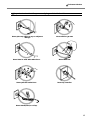
Important notes about the power cord, plug, and electrical outlet
Never place any object on top or subject to
damage.
Never allow to get wet.
Never bend or twist with undue force.
Never make hot.
Never pull with undue force.
Dust may cause fire.
Never bundle, bind, or roll up.
9
Important Notes on Handling and Use
This machine is a precision device. To ensure the full performance of this machine, be sure to observe the
following important points. Failure to observe these may not only result in loss of performance, but may also
cause malfunction or breakdown.
Main Unit
This Machine Is a Precision Device
➢Handle carefully, and never subject the machine to impact or excessive force.
Install in a Suitable Location
➢Install in a location having the specified temperature and relative humidity.
➢Install in a stable location offering good operating conditions.
Important Notes on Connecting the Cables
➢Connect the power cord and the computer's input and output cables securely.
When Moving the Machine
➢When moving the machine, be sure to support the machine at its bottom, using both hands. Attempting to
move the machine by holding it at a different location may damage the machine.
10
Chapter 1:
Setup Preparation
11
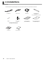
1-1 Included Items
The following items are packed together with the unit. Make sure they are all present and accounted for.
AC adapter: 1
Power cord: 1
USB cable: 1
Replaceable blade
protector: 1
* The shape depends on the model.
Blade: 1
Blade holder: 1
Pin: 1
* The blade, blade holder and pin
are installed onto the machine.
CD-ROM: 1
12
Chapter 1: Setup Preparation
User's Manual: 1
Test-use material
(Colored material): 1
Test-use application tape
(Transparent tape): 1
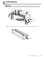
1-2 Part Names
Main Unit
Blade protector
Cutting carriage
Blade holder
Shaft cover
Pinch rollers
AC adapter jack
* Sheet adjustment lever
USB connector
Power button
Power light
* The SV-15 has sheet adjustment levers on the left and right. The SV-12/8 has a sheet adjustment lever only on the
right.
Sheet feed knob
Chapter 1: Setup Preparation
13
1-3 Installing
Deciding On an Installation Site
Install in a stable location offering good operating conditions. An unsuitable location can cause accident, faulty
operation, or breakdown.
WARNING
Never use out of doors or in any location where exposure to water or high humidity may occur. Never touch with wet hands.
Doing so may result in fire or electrical shock.
WARNING
Never place any flammable object nearby. Never use a combustible aerosol spray
nearby. Never use in any location where gases can accumulate.
Combustion or explosion may be a danger.
WARNING
Position so that the power plug is within immediate reach at all times.
This is to enable quick disconnection of the power plug in the event of an emergency.
Install the machine next to an electrical outlet. Also, provide enough empty space to
allow immediate access to the electrical outlet.
CAUTION
Install in a location that is level and stable.
Installation in an unsuitable location may cause an accident, including a fall or tipover.
Unsuitable Installation Sites
➢Locations subject to shaking or vibration
➢Locations where the floor is tilted, not level, or unstable
➢Dusty locations
➢Locations exposed to considerable electrical or magnetic noise, or other forms of electromagnetic energy
➢Locations with poor heat radiation
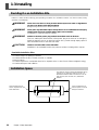
Installation Space
The material moves forward and backward during
cutting. Do not place any objects in front of or
behind the material. Make sure that there are no
obstructions (such as a wall, etc.) behind the
machine.
Leave enough space so
that no objects touch the
sheet feed knob.
14
Chapter 1: Setup Preparation
Leave enough space so
that the power cord can
always be reached.
1-3 Installing
Removing the Packing Materials
Tape and packing materials are attached to the machine to protect it from shocks during transportation. When installation is complete, remove these materials.
➢Remove all packing materials. Any that remain may cause faulty operation or breakdown when the power is
switched on.
Packing materials
Chapter 1: Setup Preparation
15
1-3 Installing
Connecting the Cables
WARNING
Connect to an electrical outlet that complies with this machine's ratings (for voltage, frequency, and current).
Incorrect voltage or insufficient current may cause fire or electrical shock.
WARNING
Handle the power cord, plug, and electrical outlet correctly and with care. Never
use any article that is damaged.
Using a damaged article may result in fire or electrical shock.
WARNING
When using an extension cord or power strip, use one that adequately satisfies the
machine's ratings (for voltage, frequency, and current).
Use of multiple electrical loads on a single electrical outlet or of a lengthy extension cord
may cause fire.
WARNING
Use only brand-name AC adapters and power cords compatible with this machine.
The use of an incompatible product could lead to an accident.
DO NOT connect
a USB cable at
this point.
Power cord
AC adapter
AC adapter Jack
Power rating
Electrical
outlet
USB cable
You make the connection to the computer using the included USB cable.
Connect the USB cable at the time indicated in the driver installation procedures. Driver installation may fail and
the machine may become unusable if you connect a USB cable before starting installing the driver.
☞ p 20 "Installing the Driver"
Important Notes on USB Connection
➢Never use a USB hub or the like.
16
Chapter 1: Setup Preparation
Chapter 2:
Installing Software
This section describes how to install the included software.
17
2-1 About the Included Software
The included CD-ROM contains the following software.
Software for Windows
■ STIKA Driver
This is a Windows-based driver required for sending data from a computer to the machine. Be sure to install it.
■ STIKA Navi
This is software that lets you operate the machine from Windows. It can be used to move the blade and test the
material feed. It is automatically installed when the STIKA driver is installed.
■ Roland CutStudio
Roland CutStudio is software that allows you to create cutting data and easily perform cutting operations.
■ CutStudio Plug-in for Adobe Illustrator
This is an Illustrator software plug-in that lets you cut from data created in Adobe Illustrator.
■ CutStudio Plug-in for CorelDRAW
This is a CorelDRAW software plug-in that lets you cut from data created in CorelDRAW.
Software for Macintosh
■ CutStudio Plug-in for Adobe Illustrator
This is an Illustrator software plug-in that lets you cut from data created in Adobe Illustrator.
18
Chapter 2: Installing Software
2-2 If You're Using a Windows
System Requirements
System Requirements for USB Connection
Making a USB connection with Windows requires use of a computer that meets all of the following system requirements. Please note that other configurations cannot be supported.
Operating Systems
Computer
Windows 98 SE (Second Edition)/Me/2000/XP
1) Computers preinstalled with Windows 98 SE/Me/2000/XP at the time of purchase
(This includes such computers later upgraded to Windows Me/2000/XP.)
2) Computers on which USB operation is assured by the manufacturer of computers
System Requirements for the Roland CutStudio
Operating Systems
Computer
Drive
Monitor
Windows 98 SE (Second Edition)/Me/2000/XP
Memory (RAM)
Free hard-disk space required for
installation
128 MB or more recommended
Computer running Windows
CD-ROM drive
Windows-compatible monitor capable of displaying of 16 bit color (High
Color) or more
10 MB
System Requirements for the STIKA Driver
Operating Systems
Computer
Windows 98 SE (Second Edition)/Me/2000/XP
1) Computers preinstalled with Windows 98 SE/Me/2000/XP at the time of purchase
(This includes such computers later upgraded to Windows Me/2000/XP.)
2) Computers on which USB operation is assured by the manufacturer of computers
Chapter 2: Installing Software
19
2-2 If You're Using a Windows
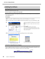
Installing the Software
Installing the Driver
STIKA Navi is installed along with the driver.
Do Not Connect to Computer Until Instructed
Do not connect the machine to the computer until instructed to do so. Failure to follow the correct procedure may
make installation impossible.
☞ p 54 "What to Do If"
Procedure
➊ Before you start installation and setup, make sure the USB cable is not connected.
➋ Log on to Windows. If you are installing under Windows 2000/XP, log on as "Administrators" right.
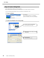
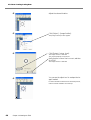
➌
Insert the included CD-ROM into the CD-ROM
drive.
After a short wait, the setup menu shown at left appears.
➍
Click [Install].
The Installation and Setup Guide appears.
If you're using Windows 98 SE, Windows Me, or Windows 2000, the Installation and Setup Guide and the
Setup program appear.
➎ Follow the instructions in the Installation and Setup Guide to finish installing.
Setup program
(Windows 98 SE/Me/2000)
Installation and Setup Guide
If the [Driver Setup] Window Doesn't Appear
If you're using Windows 98 SE, Windows Me, or Windows 2000 and the Setup program doesn't appear, first
check the taskbar at the bottom of the screen. If [Driver Setup] is displayed, the program is running. Go to the
taskbar and click [Driver Setup] to display the window for the Setup program.
Taskbar
20
Chapter 2: Installing Software
Click this.
2-2 If You're Using a Windows
Installing CutStudio
Install the cutting software "CutStudio."
Procedure
➊
Display the setup menu of the Roland STIKA Software Package.
➋
Click [Install].
The setup window appears.
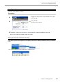
➌ Thereafter, follow the instructions in the messages to complete installation and setup.
Next, you install the Windows Advanced Guide.
Viewing the Roland CutStudio Online Help
Click [Start], point to [All Programs] (or [Programs]), then point to [Roland CutStudio], point to [CutStudio
Help].
* You can also display the Online Help from the CutStudio menu.
Chapter 2: Installing Software
21
2-2 If You're Using a Windows
Installing the Windows Advanced Guide
Procedure
➊
Display the setup menu of the Roland STIKA Software Package.
➋
Click [Install].
The setup window appears.
➌ Thereafter, follow the instructions in the messages to complete installation and setup.
➍ At the setup menu, go to the upper right and click the [X] to close the window.
Viewing the Windows Advanced Guide
Click [Start], point to [All Programs] (or [Programs]), then point to [Roland SV Series Manual], point to
[Advanced Guide].
Installing CutStudio Plug-in
For information about installing the CutStudio Plug-in, refer to the "Windows Advanced Guide" (electronic
format).
22
Chapter 2: Installing Software
2-3 If You're Using a Macintosh
System Requirements
Your Macintosh must fulfill the following requirements in order to use STIKA for cutting operations.
OS: Mac OS 9 or later (Adobe Illustrator 9/10/CS run without problem)
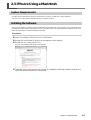
Installing the Software
The included CD-ROM contains the "Mac OS Installation and Setup Guide," which explains how to install and set up
the software and Macintosh Cutting Guide. If you’re using a Macintosh, follow the steps below to display the file, then
follow the explanation to perform installation and setup.
Procedure
➊ Insert the included CD-ROM into the CD-ROM drive.
➋ Double-click the [Roland SV Series] icon that appears on the desktop.
➌ Double-click the "Install_e.html" icon.
The [Mac OS Installation and Setup Guide] appears.
➍ Thereafter, follow the instructions in the [Mac OS Installation and Setup Guide] to install and set
up the software and Macintosh Cutting Guide.
Chapter 2: Installing Software
23
24
Chapter 3:
Performing Cutting
This describes basic cutting operations under Windows. For other operations not covered in this chapter, refer to the "Windows Advanced Guide"
(electronic format).
25
3-1 What to Know Before Cutting
Useable Material Types
Thefolowingmaterialscanbeusedwiththismachine.
Size
Material Types
(*)
SV-15
SV-12
SV-8
Width: 360 to 381 mm
(14-1/8 to 15 in.)
280 to 305 mm (11 to 12 in.)
(A3 length, A4 width)
Length: 1100 mm
(43-1/4 in.) or less
Width: 280 to 305 mm
(11 to 12 in.)
(A3 length, A4 width)
Length: 1100 mm
(43-1/4 in.) or less
Width: 200 to 215 mm
(7-13/16 to 8-7/16 in.)
(A4 length)
Length: 1100 mm
(43-1/4 in.) or less
Vinyl chloride material (material section thickness is 0.1 mm or less, thickness including the backing
paper is 0.3 mm (0.012 in.) or less)
Label paper (Thickness including backing paper is 0.3 mm (0.012 in.) or less)
*Themachinemaynotcutcertainmaterials.
➢Do not use material that is in a condition indicated below. It may come loose or jam during cutting.
The material is
curled upward.
The material edge is
not straight
The left and right
edges of the material
aren't parallel
The material is longer than
1100 mm (43-1/4 in.)
Using Roll Material
If you're using a roll of material, make sure to add a margin greater than 40 mm (1-5/8 in.) to the cutting area
prior to cutting the material from the roll. Material with a maximum length of 1100 mm (43-1/4 in.) can be loaded
into the machine. However, the cutting area is only 1000 mm (39-5/16 in.).
Up to
1100 mm
(43-1/4 in.)
➢Cut the material at a right angle. If the front edge of the material is uneven, it may feed improperly during
cutting and could skew diagonally and come loose.
26
Chapter 3: Performing Cutting
3-1 What to Know Before Cutting
Chapter 3: Performing Cutting
27
3-2 Cutting
Let's look at the basic cutting method while creating the sticker indicated to the right.
Follow the operations in the order indicated below.
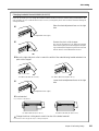
Step 1: Load Material
Procedure
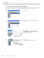
➊ Turn the machine off.
➋
Pinch roller
Verify that the material is narrow enough to be
loaded and that it touches the pinch rollers.
If you are using the SV-15 model, adjust the pinch
rollers to the material width and then advance the
material to touch the pinch rollers.
☞ p 29 "Changing Loadable Material Width (for SV-15)"
Make the material edges even
➌
Verify that the left edge of the material is parallel with the guide line.
* If it is not, trim the excess material from the edge of
the material that is touching the pinch rollers until
the left edge is parallel with the guide line.
Guide line
➍
Turn the sheet feed knob and move the material into the machine and then back out. Verify
that the material does not come loose.
* Reload the material if it becomes skewed or if it
comes loose.
Sheet feed knob
➎
Align the material edge with the marks at the
back of the blade protector.
Loading the Included Test-use Material
The direction to load the included test-use material differs depending on the machine model.
SV-15/12 ··· Sideways (Landscape)
SV-8 ··· Lengthwise (Portrait)
If you are using the SV-15 model, change the loadable material width to 280 to 305 mm (11 to 12 in.).
☞ p 29 "Changing Loadable Material Width (for SV-15)"
28
Chapter 3: Performing Cutting
3-2 Cutting
Changing Loadable Material Width (for SV-15)
In the SV-15 model, you can change the loadable material width to match the material being loaded (360 to 381
mm (14-1/8 to 15 in.) or 280 to 305 mm (11 to 12 in.)). Change the pinch roller location and driver settings to
change the width.
➊
Raise the sheet adjustment lever on the right
side.
Sheet adjustment lever (right)
➋
Remove the pinch-roller stopper.
Do not use excessive force to widen the opening
when removing the pinch-roller stopper. If the opening is widened, the stopper may become loose and
fall out when it is next attached to the unit.
Pinch-roller stopper
➌ Move the right side pinch roller to match the width of the material being loaded and attach the
pinch-roller stopper.
Pinch roller
Pinch roller
For 280 to 305 mm (11 to 12 in.)
➍
For 360 to 381 mm (14-1/8 to 15 in.)
Lower the sheet adjustment lever on the right
side.
Sheet adjustment lever (right)
➎ Load material.
☞ p 28 "Step 1: Load Material"
For 280 to 305 mm (11 to 12 in.)
For 360 to 381 mm (14-1/8 to 15 in.)
➏ Change the driver cutting area to match the size of the loaded material.
☞ Procedures 1 and 2 on page 30 "Step 2: Creating Cutting Data"
Chapter 3: Performing Cutting
29
3-2 Cutting
Step 2: Create Cutting Data
Use the cutting software "CutStudio" to create cutting data.
Refer to "Roland CutStudio Online Help" for a detailed explanation of CutStudio operations and features.
➢If you are using Windows 2000/XP, log on to Windows as "Administrator" right.
1. Start CutStudio.
Click [Start].
Point to [All Programs] (or [Program]) –
[Roland CutStudio], then click [CutStudio].
2. Make the settings for the cutting range.
➊
➋
➌
30
Chapter 3: Performing Cutting
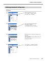
Click [File], then click [Cutting Setup].
The [Cutting Setup] screen appears.
Select the name of the model you are using
under [Name].
Click [Properties].
The [Properties] screen appears.
3-2 Cutting
➍
➎
Click the [Size] tab.
Set the cutting range to match the loaded
material size.
For the width, click [ ] to select either 250 (9.84 in.)
or 340 mm (13.39 in.) (SV-15 only).
(* Set to 250 mm (9.84 in.) if you are using the
included test-use material.)
The width cannot be changed on the SV-12/8
models.
For the length, set a range that subtracts the margin from the loaded material length.
☞ p 58 "Cutting Range"
➏
➐
Click [OK].
Click [OK] again to close the [Cutting Setup]
screen.
The cutting range has now been set.
The white area is the cutting
range. Text or shapes drawn
outside this range are not cut.
Chapter 3: Performing Cutting
31
3-2 Cutting
3. Insert text and shapes to create the cutting data.
In this example, we'll enter the word "SALE" as the text and draw a frame around it to make it easier to peel of
f later.
➊
Click [
➋
Click anywhere in the white area, then type in
"SALE."
➌
Click [
].
].
Displayed around the text are ■ and ▼ symbols.
Drag the ■ and ▼ symbols for the text box to
change the size of the text.
Click, then drag to change to
the required size.
➍
32
Click the upper-left corner, then
drag to the lower right to change
to the required size.
Chapter 3: Performing Cutting
Click [
].
Draw a rectangle around the "SALE" text.
3-2 Cutting
➎
Click [
].
Use the mouse to select an area containing the
text and the rectangle.
When you select this, the line turns blue.
Move the position to the top of the window,
near the origin point.
Origin point
Move the pointer to inside the text.
When the shape of the pointer
changes to a cross, drag to move.
➏
Click [Save].
➐
For "Save in," choose the folder you want.
Enter the file name, then click [Save].
The [Save As] screen appears.
The data you created is saved.
Important Note When Saving Data
The cutting range set in [File] – [Cutting Setup] – [Properties] is not saved. The next time you import data, go to
the [Cutting Setup] menu and redo the setting for the cutting range.
Chapter 3: Performing Cutting
33
3-2 Cutting
Step 3: Perform Cutting
Before cutting, verify that Step 1 "Load Material" and Step 2 "Create Cutting Data" preparation have been completed.
Procedure
➊
Press the power button and turn the machine
on.
The power light flashes. The cutting carriage moves to
the left edge of the machine. Once the light changes
to a steady illumination, the machine is ready to cut.
➋
Click [Cutting].
➌
Click [OK].
The cutting data is sent from the computer and cutting
starts.
Cutting of the "SALE" text and the box ends.
34
Chapter 3: Performing Cutting
3-2 Cutting
➍ Press the power button and turn power off.
Verify that the power light extinguishes.
➎
Turn the sheet feed knob and remove the material.
To Stop Cutting While in Progress
➊
Press the power button and turn the machine
off.
➋
Press the power button again and turn the machine on.
The cutting carriage returns to the left edge.
If you need to cut the material again, first remove and then reload it.
➢You can also cancel a cutting operation from STIKA Navi. For more information, refer to the "Windows
Advanced Guide" (electronic format).
Chapter 3: Performing Cutting
35
3-2 Cutting
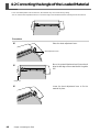
Step 4: Apply the Cut Material
Use application tape to affix the cut material. Cut the application tape to the required size for use.
Before applying, thoroughly clean the surface where you want to affix the material to remove any dust or grease.
Procedure
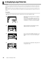
➊
Remove the excess tape so that only text remains.
Use a commercially-available tweezers to remove small
pieces of tape better .
➋
Application tape
Cut the application tape to the required size.
Cover the cut material flush with the application tape to prevent any air from getting underneath, then transfer the material.
You can transfer the material easily by using a commercially available squeegee or the flat part of a ruler
or the like to rub the cut material from above the application tape.
➌
Affix the material together with the joined application tape to the target object, then press
down on it from above.
➍
Make sure the material is affixed to the object,
then slowly peel off the application tape.
If air becomes trapped between the material and the
application surface, forming an air bubble, then use a
needle to pop the bubble and press out the air to form
a complete seal.
➎
This completes the procedure for attaching the
material.
Material After Cutting
Transfer the cut material to the application tape and affix it to the object as soon as possible. Any dust that builds
up on the surface of the material can make it difficult for the application tape to stick.
36
Chapter 3: Performing Cutting
Chapter 4:
Mastering the STIKA
This describes in details how to adjust the blade extension amount, how
to correct the angle of the loaded material, and how to create cutting
data.
37
4-1 Optimizing the Cutting Quality for the Material
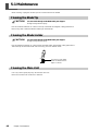
Check the Cutting Quality for the Material
Perform a cutting test to check the cutting quality for the material. Perform a cutting test when changing the material
type and when adjusting the blade extension.
➢Make sure to load material before performing a cutting test. Failure to do so could damage the blade and blade
protector.
➢Do not move the cutting carriage with your hand. Doing so could damage the machine.
➢Do not touch any moving parts while the machine is operating. Doing so could cause a malfunction.
Procedure
➊ Load the material.
➋
With the power light on, hold down the power
button for 2 seconds or longer.
2 seconds
or longer
➌
Remove your finger once the cutting carriage
starts to move.
Cutting begins from the location that the blade is currently located and the shape indicated in the figure is
cut.
To consecutively perform cutting tests, hold down the
power button for 2 seconds or longer once the prior
cutting operation has finished. This cutting test is done
in an area that doesn't overlap with the previous cutting location.
➍ Peel off the cut shapes and check the cutting quality for the material.
The material cutting quality is controlled by the blade extension amount. Adjust the blade extension amount
depending upon the state of the material when it is peeled off.
☞ p 39 "Adjusting the Blade Extension Amount"
The cross-shaped blade leaves faint traces on the material's backing paper
This is the optimal blade extension amount. No adjustment is required.
The material is difficult to peel from the backing paper
The blade trace is indistinct
Cutting results shift
Extend the blade.
The blade cuts into the backing paper
The blade cuts through the backing paper
The material curls during cutting
Retract the blade.
38
Chapter 4: Mastering the STIKA
Optimal blade
extension amount
The blade extension
is too short
The blade extension
is too long
4-1 Optimizing the Cutting Quality for the Material
Adjusting the Blade Extension Amount
CAUTION
Do not touch the tip of the blade with your fingers.
Doing so may result in injury.
Procedure
➊
Turn the machine off.
Loosen the screw, remove the blade holder.
Blade holder
Screw
➋
Adjust the blade extension amount.
Turn the tip of the blade holder as indicated in the figure to extend the blade tip. Turn the large cap once to
extend the blade tip by 0.1mm.
0.1 mm
The blade tip essentially
cannot be seen from the
blade holder.
➌
Support the screw from below and insert the
blade holder.
Tight contact
Support the
screw from
below.
➍
Tighten the screw.
Tug the blade holder upward to make sure it does not
come loose.
Screw
➎ Carry out the cutting test and check the cutting quality for the material.
Repeat until optimal cutting quality is attained.
☞ p 38 "Check the Cutting Quality for the Material"
Rough Estimate for the Amount of Blade Extension
Use the following dimension as a rough estimate for setting the amount of blade extension.
Amount of blade
Thickness of the
=
+
extension
media portion
Thickness of the
backing paper
2
* Suggested point
The optimal setting has been achieved when there are
faint lines on the backing paper when a cutting test is
executed.
Holder
Material
portion
Backing paper
portion
Half of the
backing paper
Blade
Amount of blade is
approximately equal
to cutting-in amount
Chapter 4: Mastering the STIKA
39
4-2 Correcting the Angle of the Loaded Material
If it is not loaded parallel into the machine, the material may come loose during cutting.
You can use the sheet adjustment lever to correct the angle of the material without removing it from the machine.
Procedure
➊
Raise the sheet adjustment lever.
Sheet adjustment lever
➋
Move the material backward and forward and
align the left edge of the material with the guide
line.
Guide line
➌
40
Chapter 4: Mastering the STIKA
Lower the sheet adjustment lever to fix the
material in place.
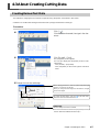
4-3 About Creating Cutting Data
Creating Various Text Data
The method for changing the size and font of input text using "Properties" is described in this section.
CutStudio can use Windows TrueType-based fonts and OpenType fonts based on TrueType.
Procedure
➊
Click [
].
Click the desired area and, then type in the characters.
➋
Click [Format] – [Font].
The [Properties] screen appears.
You can also display the [Properties] screen as indicated below.
· Click [Format] – [Properties].
· Click [Properties] on the mouse right-click shortcut
menu.
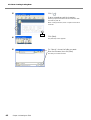
➌ Change the text size and design.
When changing the text size, enter into [Text Height] the height
at which you want to cut the text.
When you change the text height, the text width is changed
to the same degree.
To change the text design, click the [ ] in the field underneath Font and select the desired font.
Click [OK].
The font design and size are modified.
For more information about the [Properties] screen,
refer to "Roland CutStudio Online Help."
Chapter 4: Mastering the STIKA
41
4-3 About Creating Cutting Data
➍
Click [
].
Draw a rectangle around the characters.
Drawing a square around the text will make the material easier to peel off.
When cutting small text, draw a square around each
character.
Drag.
➎
Click [Save].
➏
For "Save in," choose the folder you want.
Enter the file name, then click [Save].
The [Save As] screen appears.
The data you created is saved.
42
Chapter 4: Mastering the STIKA
4-3 About Creating Cutting Data
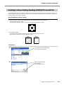
Creating Contour Data by Reading a BMP/JPG Format File
Windows BMP/JPG files can be read by CutStudio, the contours of the image detected, and the resulting image cut. It
may be difficult to detect the contours of certain types of read images. Keep the following conditions in mind when
selecting images to be read by CutStudio.
Data Conditions for Clean Cutting
➢Colors must not contain continuous tones and color borders must be clearly defined.
We recommend black and white.
Scanned photos generally contain continuous tones and are unsuitable for cutting.
➢Increasing resolution
The optimal resolution differs depending upon image complexity and cutting size.
High-resolution data takes longer for CutStudio to read.
72 dpi
300 dpi
Procedure
➊
Click [File], then click [Import].
➋
Select the desired file.
Click [Open].
The [Import] screen appears.
The read data is laid out.
Chapter 4: Mastering the STIKA
43
4-3 About Creating Cutting Data
➌
Adjust the size and location.
➍
Click [Object] – [Image Outline].
➎
Click [Extract Contour Lines].
The [Image Outline] screen appears.
The image contour is detected.
The contour displays as a blue line.
Verify that the contour line is correct, and then
click [OK].
The image contour is detected.
➏
You can use the object tool to reshape the image if needed.
For more information about how to use the object tool,
refer to "Roland CutStudio Online Help."
Object tool
44
Chapter 4: Mastering the STIKA
4-3 About Creating Cutting Data
Deleting Undesired Cutting Lines
CutStudio can be used to delete contour line that is not needed.
Procedure
➊
Select the detected contour line.
Click [Object] – [Break Polyline].
The image contour is separated.
➋
Click on the undesired cutting line.
Click [Edit] – [Delete].
The undesired cutting line is deleted.
The read data remains and is not deleted.
➌
Drag the mouse to select the remaining contour lines.
To select all contour lines on the CutStudio screen, click
[Edit] – [Select All].
Hold down the Shift key and click contour lines to select only those desired.
➍
Click [Object] – [Integrate Polylines].
The separated contour line is made whole.
Chapter 4: Mastering the STIKA
45
4-4 Applying Large Materials
As the size of the material to be applied increases, it will become increasingly difficult to keep the entire material from
slipping during application and to prevent air bubbles from becoming trapped between the material and application
surface.
Spray the application surface with detergent-containing water to allow you to move and place the material in the
desired location, and to decrease the likelihood of bubbles becoming trapped between the application surface and
material.
Procedure
➊ Prepare the cut material and tape the material from the top with application tape.
46
➋
Remove any dust and grease from the application surface.
Use a commercially available spray bottle to liberally spray the application surface with water
containing 2 to 3 drops of a neutral detergent.
➌
Apply the material to the application surface.
➍
Use a commercially available squeegee or the
flat part of a ruler to remove all remaining moisture.
➎
Once all water has evaporated, slowly peel off
the application tape.
Chapter 4: Mastering the STIKA
Adjust the material location and angle.
Chapter 5:
Maintenance
This describes how to clean the machine and replace the blade.
47
5-1 Maintenance
When cleaning, unplug the machine's power cord and remove all material.
Cleaning the Blade Tip
CAUTION
Do not touch the tip of the blade with your fingers.
Doing so may result in injury.
Dust and material adhesive can collect on the tip of the blade and degrade cutting performance.
Remove any dust or material adhesive adhering to the blade tip.
Cleaning the Blade Holder
CAUTION
Do not touch the tip of the blade with your fingers.
Doing so may result in injury.
Dust and adhesive material can collect within the blade holder and degrade cutting performance.
Take off the tip of the blade holder and remove any pieces of material inside.
Turn the tip of the blade
holder as indicated in the
figure to remove.
Cleaning the Main Unit
Use a dry cloth to gently wipe any dirt from the main unit.
Never use a solvent such as thinner or benzene.
48
Chapter 5: Maintenance
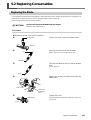
5-2 Replacing Consumables
Replacing the Blade
If you adjust the blade amount and implement a cutting test several times, and the machine still does not properly cut
the material, the blade tip may be worn or damaged. Replace with a new blade.
Before replacing the blade, remove the material.
CAUTION
Do not touch the tip of the blade with your fingers.
Doing so may result in injury.
Procedure
➊ Unplug the power cord from the machine.
➋
Blade holder
Loosen the screw, remove the blade holder.
Screw
➌
Press the pin and remove the old blade.
Pin
Press in until you can no longer see the pin.
Old blade
➍
Press the new blade in until you hear an audible
click.
The pin pops out.
Blade
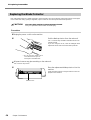
➎
Support the screw from below and insert the
blade holder.
Tight contact
Support the
screw from
below.
➏
Tighten the screw.
Blade holder
Tug the blade holder upward to make sure it does not
come loose.
Screw
Chapter 5: Maintenance
49
5-2 Replacing Consumables
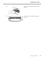
Replacing the Blade Protector
Even if the blade protector is slightly damaged, cutting operation will not be affected. If the blade protector is damaged
to the extent that cutting quality is degraded, replace it with the included replacement blade protector.
CAUTION
The cutter knife used here is sharp and poses a hazard.
Carry out operations with caution to avoid injury.
Procedure
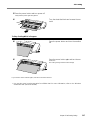
➊ Unplug the power cord from the machine.
➋
Peel the blade protector from the main unit.
Use a commercially available retractable knife to facilitate removal.
If you are using the SV-15, raise the left/right sheet
adjustment levers and remove the blade protector.
* Do not place your hands in front
of the direction that you are
moving the retractable knife.
➌ Wipe and remove any glue remaining on the main unit.
Use a cloth to wipe clean.
➍
Place the replacement blade protector into the
machine.
Align the blade protector using the reference line displayed on the machine.
Reference line
50
Chapter 5: Maintenance
5-2 Replacing Consumables
➎
Peel off the double-sided tape and affix the blade
protector.
➏
For the SV-15, lower the left/right sheet adjustment levers.
Sheet adjustment levers
Chapter 5: Maintenance
51
52
Chapter 6:
Appendix
53
6-1 What to Do If
This section describes what to do if you encounter a problem while using the machine. Refer to this first, before assuming that a malfunction has occurred. The method for
resolving problems not listed below are indicated in the
"Windows Advanced Guide" or "Macintosh Cutting Guide"
(electronic format). Use both as necessary.
Is there a build-up of material adhesive or dust within
the blade holder?
Take off the tip of the blade holder and remove any pieces
of material inside.
☞ p 48 "Cleaning the Blade Holder"
Are there any scratches on the blade protector?
The machine does not run properly
Is the cable properly connected?
If the power cord or USB cable are not properly connected,
refer to the following page and connect properly.
☞ p 16 "Connecting the Cables"
If the blade protector is damaged, correct cutting of material may be impossible even if the machine's settings and
the installation of the blade and blade holder are all correct. Replace with a new blade protector.
☞ p 50 "Replacing the Blade Protector"
Is the blade holder damaged or worn?
Are the settings for the driver correct?
Replace with a new blade holder.
Make sure the communication port is set correctly.
The cut location is shifted forward/back
Is the power lamp flashing?
The problem is a communication or command error.
Turn power off, verify the cable connection and computer/
software settings.
Power does not turn off even when the power button is pressed
Unplug the AC adapter from the machine.
The cut incisions are not clean
Is the blade extension amount optimal?
Check whether the blade extension amount has been adjusted.
☞ p 39 "Adjusting the Blade Extension Amount"
Did the material come up against an obstruction
while it was being cut?
Do not place anything in front of or behind the machine.
This can obstruct the material feed and cause the cut location to shift.
Is the blade extension amount optimal?
Check whether the blade extension amount has been adjusted.
☞ p 39 "Adjusting the Blade Extension Amount"
The cut location is shifted left/right
If the cut location shifts as indicated below, check the following.
Is the blade holder fixed in place?
Firmly attach so that the screw does not loosen during cutting.
Is the tip of the blade broken?
Replace with a new blade.
☞ p 49 "Replacing the Blade"
Parts of the material are not continuously cut
The spacing between
characters differs
Is the tip of the blade broken?
Replace with a new blade.
☞ p 49 "Replacing the Blade"
Is dust or material adhesive attached to the blade
tip?
Remove the blade and clean the tip.
☞ p 48 "Cleaning the Blade Tip"
54
Chapter 6: Appendix
A location different
than the data indicates is cut
6-1 What to Do If
Is the blade extension amount optimal?
Check whether the blade extension amount has been adjusted.
☞ p 39 "Adjusting the Blade Extension Amount"
Does the cutting carriage move abnormally and do
you hear a strange noise?
Remove any dust or material adhesive adhering to cutting
carriage guide shaft and then lubricate.
☞ p 57 "Shaft Lubrication"
The material shifts during cutting
Is the material length 500 mm (19-5/8 in.) or longer?
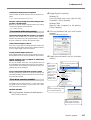
➋ Display [System Properties].
Windows XP
Click the [Start] menu, then right-click [My
Computer]. Click [Properties].
Windows 2000
Right-click [My Computer] on the desktop.
Click [Properties].
➌ Click
the [Hardware] tab, then click [Device
Manager].
The [Device Manager] appears.
If they are 500 mm (19-5/8 in.) or longer, certain types of
material may shift during cutting. Either switch to a different kind of material, or shorten the material length.
Is the material length too short?
If too short, certain types of material with little rigidity may
shift during cutting. Either switch with a different material
or use a longer length of the same material.
Are the material edges evenly cut?
If the material edges are cut at an angle, trim the excess so
that the material is even with the guidelines when loaded.
Did the material come up against an obstruction
while it was being cut?
Do not use material wider than can be handled. The left
and right edges of the material will touch the inner surfaces
of the machine and in addition to shifting the location, the
material may also be damaged.
Are you using material that has creases or folds?
This may prevent the material from properly feeding and
may shift the material position. Remove the creases or folds
and reload the material.
If the driver cannot be installed
If installation quits partway through, or if the wizard does
not appear when you make the connection with a USB
cable, take action as follows.
Windows XP/2000
➍ Delete the model name in use (or [Unknown
Device]).
At the [View]
menu, click
[Show hidden
devices].
Go to the [Action] menu, and
click [Uninstall].
Find [Printers]
or [Other
device], then
double-click it.
Click the model name in use
(or [Unknown Device]).
➊ If the [Found New Hardware Wizard] appears,
click [Finish] to close it.
After the screen shown
above appears, click [OK].
Chapter 6: Appendix
55
6-1 What to Do If
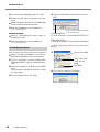
➎ Close the [Device Manager] and click [OK].
➏ Detach the USB cable connected to the com-
➎ Type in the information shown below, then click
[OK].
puter.
➐ Restart Windows, and refer to "Uninstalling the
driver" below to uninstall the driver.
➑ Redo the installation from the beginning.
☞ p 20 "Installing the Driver"
Windows 98 SE/Me
* In this illustration, drive D is specified
as the CD-ROM drive.
➊ Refer
Windows 2000/XP
(CD-ROM drive letter ):\Drivers\WIN2KXP\SETUP.EXE
➋ Redo the installation from the beginning.
Windows 98 SE/Me
(CD-ROM drive letter):\Drivers\WIN9X\Setup.exe
to "Uninstalling the driver" below to
uninstall the driver.
☞ p 20 "Installing the Driver"
Uninstalling the driver
When uninstalling the driver, perform following operation.
The Setup program starts and the [Driver Setup] window
appears.
➏
Choose [Uninstall].
➊ Before
you start uninstallation of the driver,
unplug the USB cables from your computer.
➋ Log on to Windows. If you are installing under
Windows 2000/XP, log on as “Administrators”
right.
➌ Insert the included CD-ROM into the CD-ROM
drive.
Go to the upper right and click the [X] to close
the setup menu.
➍ From the [Start] menu, click [Run].
56
Chapter 6: Appendix
Select the model
name you are
using.
Click [Start].
➐ Click [Yes] to restart the computer.
6-2 Shaft Lubrication
The material may not cut properly if dust and material adhesive adhere to the cutting carriage guide shaft. If the following
symptoms are present, remove the shaft cover and lubricate the shaft located as indicated in the figure. Use a machine oil to
lubricate.
It does not move smoothly
You hear an abnormal noise
Procedure
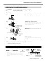
➊ Unplug the power cord from the machine.
➋
Remove the shaft cover.
➌
Wipe and remove dust adhering to the shaft.
➍
Use machine oil to lightly lubricate the shaft section indicated in the figure to the left.
Use a Phillips head screwdriver to remove the screws.
Using too much oil can cause the material to stain.
➎ Replace the shaft cover and screw into place.
Chapter 6: Appendix
57
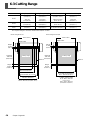
6-3 Cutting Range
Cutting Range (width)
Cutting Range (length) Loadable Material Width Loadable Material Length
340 mm
(13-3/8 in.)
1000 mm
(39-5/16 in.)
360 to 381 mm
(14-1/8 to 15 in.)
1100 mm
(43-1/4 in.)
250 mm
(9-13/16 in.)
1000 mm
(39-5/16 in.)
280 to 305 mm
(11 to 12 in.)
1100 mm
(43-1/4 in.)
SV-12
250 mm
(9-13/16 in.)
1000 mm
(39-5/16 in.)
280 to 305 mm
(11 to 12 in.)
1100 mm
(43-1/4 in.)
SV-8
160 mm
(6-1/4 in.)
1000 mm
(39-5/16 in.)
200 to 215 mm
(7-13/16 to 8-7/16 in.)
1100 mm
(43-1/4 in.)
SV-15
· The required margin to send the material forward/back is taken.
When using the SV-15
When using the SV-12/8
Pinch rollers
Pinch rollers
Blade holder
Blade holder
Margin
10 mm
(3/8 in.)
Margin
10 mm
(3/8 in.)
Maximum
1000 mm
(39-5/16 in.)
Maximum
1000 mm
(39-5/16 in.)
Cutting range
Cutting range
Material
Margin
30 mm
(1-3/16 in.)
Margin
30 mm
(1-3/16 in.)
Cutting range (width)
250 mm (9-13/16 in.)
Loadable material width
280 to 305 mm (11 to 12 in.)
Cutting range (width)
340 mm (13-3/8 in.)
Loadable material width
360 to 381 mm (14-1/8 to 15 in.)
58
Material
Chapter 6: Appendix
Cutting range (length)
SV-12: 250 mm (9-13/16 in.)
SV-8 : 160 mm (6-1/4 in.)
Loadable material width
SV-12: 280 to 305 mm
(11 to 12 in.)
SV-8 : 200 to 215 mm
(7-13/16 to 8-7/16 in.)
6-4 Locations of the Power Rating and Serial Number Labels
Serial number
This is require when you seek maintenance,
servicing, or support. Never peel off the label
or let it get dirty.
Power rating
Use an electrical outlet that meets the requirements
for voltage, frequency, and amperage given here.
Chapter 6: Appendix
59
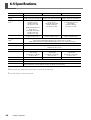
6-5 Specifications
SV-15
Cutting method
Maximum cutting
range
Useable material
size (*1)
SV-12
SV-8
Media-moving method
Width: 340 mm (13-3/8 in.) Width: 250 mm (9-13/16 in.)
Width: 160 mm (6-1/4 in.)
Length: 1000 mm (39-5/16 in.) Length: 1000 mm (39-5/16 in.) Length: 1000 mm (39-5/16 in.)
Width: 360 to 381 mm
(14-1/8 to 15 in.)
Length: 1100 mm
(43-1/4 in.) or less
Width: 280 to 305 mm
(11 to 12 in.)
(A3 length, A4 width)
Length: 1100 mm
(43-1/4 in.) or less
Width: 200 to 215 mm
(7-13/16 to 8-7/16 in.)
(A4 length)
Length: 1100 mm
(43-1/4 in.) or less
12 to 40 mm/sec.
(7/16 to 1-9/16 in./sec.)
12 to 40 mm/sec.
(7/16 to 1-9/16 in./sec.)
Width: 280 to 305 mm
(11 to 12 in.)
(A3 length, A4 width)
Length: 1100 mm
(43-1/4 in.) or less
Maximum cutting speed
12 to 100 mm/sec.
(7/16 to 3-7/8 in./sec.)
Useable material
type (*2)
Vinyl chloride material (material section thickness alone is 0.1 mm or less,
thickness including backing paper is 0.3 mm (0.012 in.) or less)
Label paper (Thickness including backing paper is 0.3 mm (0.012 in.) or less)
Interface
Power supply
USB 1.1
Dedicated AC adapter Input: AC 100 V ± 10%, 50/60 Hz 1.7A
Output: DC 19 V, 2.1 A
Power consumption
Dimensions
Weight
Acoustic noise level
Operating environment
Included items
Approx. 20 W (including AC adapter)
522 (W) × 205 (D)
× 115 mm (H)
(20-5/8 (W) × 8-1/8 (D)
× 4-1/2 in. (H))
440 (W) × 205 (D)
× 115 mm (H)
(17-3/8 (W) × 8-1/8 (D)
× 4-1/2 in. (H))
340 (W) × 205 (D)
× 115 mm (H)
(13-3/8 (W) × 8-1/8 (D)
× 4-1/2 in. (H))
3.3 Kg (7.3 lb)
2.7 Kg (6 lb)
2.2 Kg (4.9 lb)
60 dB (A) or less (according to ISO7779)
Temperature: 5 to 40˚C (41 to 104˚F), humidity: 35 to 80% (no condensation)
AC adapter, power cord, USB cable, replaceable blade protector, blade, blade holder, pin,
test-use material, test-use application tape, CD-ROM, user's manual
*1
Depending upon the type, material that is 500 mm (19-5/8 in.) or longer may shift during cutting.
*2
You may also be unable to cut some types of material.
60
Chapter 6: Appendix
Please read this agreement before opening the sealed disk package
Opening the sealed disk package implies your acceptance of the terms and conditions of this agreement.
Roland License Agreement
Roland DG Corporation ("Roland") grants you a non-assignable and non-exclusive right to use the COMPUTER
PROGRAMS in the disk package ("Software") under this agreement with the following terms and conditions.
1. Coming into Force
This agreement comes into force when you purchase and open the sealed disk package. The effective date of this
agreement is the date when you open the sealed disk package.
2. Ownership
Copyright and property of this Software, logo, name, manual and all literature for this Software belong to Roland
and its licenser. The followings are prohibited:
Unauthorized copying of the Software or any of its support files, program modules, or literature.
Reverse-engineering, disassembly, decompiling, or any other attempt to discover the source code of the Software.
3. License Restrictions
Roland does not grant you the right to sub-license, rent, assign, or transfer the rights granted under this agreement or the Software itself (including the accompanying items) to any third party.
You may not provide use of the Software through a time-sharing service and/or network system to any third party
who is not individually licensed to use this Software.
This Software may be used by one person using a single computer on which the Software is installed.
4. Reproduction
You may make one copy only of the Software for back-up purposes. The ownership of the copied Software
belongs to Roland.
You may install the Software onto the hard disk of a single computer.
5. Cancellation
Roland retains the right to terminate this agreement without notice immediately upon occurrence of any of the
following:
Violation by you of any article of this agreement
Commission by you of any serious breach of faith with respect to this agreement
6. Limitations on Liability
Roland may change the specifications of this Software or its materials without notice.
Roland shall not be liable for any damage that may be caused by the use of the Software or by exercise of the
right licensed by this agreement.
7. Governing Law
This agreement is governed by the laws of Japan, and the parties shall submit to the exclusive jurisdiction of the
courts of Japan.
R1-051220