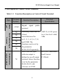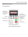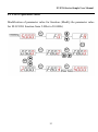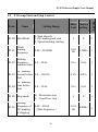
1
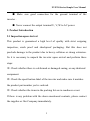
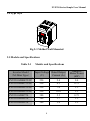
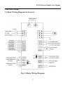
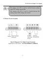
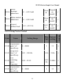
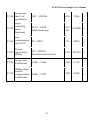
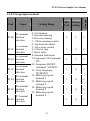
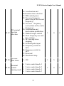
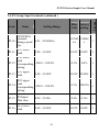
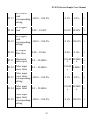
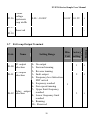
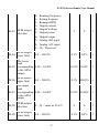
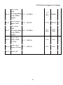
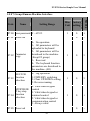
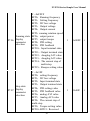
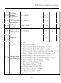
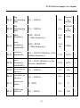
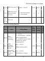
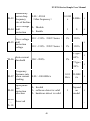
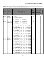
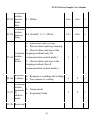
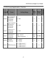
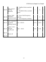
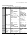
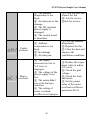
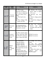
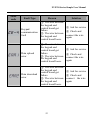
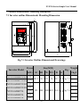
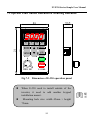
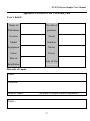
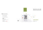
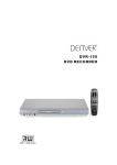
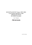
ZVF330 Series Simple User Manual
ZVF330 Series Simple User Manual
1. Foreword
Thanks for using ZVF330 Series inverter .The inverter use high quality
components, material and adopt the latest DSP control technoloogy . The
user manual provide installation, parameter setting, thourbleshooting ,and
other relevant considerations for the users.
In order to ensure proper installation and operation of the inverter. Please
read the user manual before installtion and keep it and distribute to the end
users. For more details, please visit our webite to download the user
manual.
The following items for special need to notice:
● Be sure to turn off the power when wiring .
● Electronic components inside the inverter are particularly sensitive
to static electricity. So don’t insert foreign objects into the inverter and
don’t touch the main circuit board.
● Even after cutting off the AC power, if the indicators on the keypads
doesn’t light off, it means there is high voltage inside the inverter and it is
still very danagerous. Do not touch the inner circuit or components .
1
ZVF330 Series Simple User Manual
● Make sure good connection for the ground terminal of the
inverter .
● Never connect the output terminal U, V, W to AC power.
2. Product Introduction
2.1 Inspection upon Arrival
This product is guaranteed a high level of quality with strict outgoing
inspection, crush proof and shockproof packaging. But this does not
preclude damage to the product due to heavy collision or strong extrusion.
So it is necessary to unpack the inverter upon arrival and perform these
steps:
1 Check whether there is a deformed or damaged casing, or any shattered
○
component.
2 Check the specification label of the inverter and make sure it matches
○
the product part number you've ordered.
3 Check whether the items in the packing list are in readiness or not.
○
If there is any problem with the above-mentioned contents, please contact
the supplier or Our Company immediately.
2
ZVF330 Series Simple User Manual
2.2 Demonstration of the Model
Fig.2-1 Inverter Model Demonstration
2.3 Specification Label
Fig.2-2 Inverter Label
3
ZVF330 Series Simple User Manual
2.4 Type Style
Fig.2-3 Molded Wall-Mounted
2.5 Models and Specifications
Table 2-1
Models and Specifications
ZVF330-M0R4T2/S2
220
2.4
Adaptive
Motor Power
(kW)
0.4
ZVF330-M0R7T2/S2
220
4.5
0.75
ZVF330-M1R5T2/S2
220
7.0
1.5
ZVF330-M2R2T2/S2
220
10.0
2.2
ZVF330-M0R7T4
380
2.5
0.75
ZVF330-M1R5T4
380
3.7
1.5
ZVF330-M2R2T4
380
5.0
2.2
Inverter Model
(M: Mini Type)
Input Voltage Rated Output
(V)
Current (A)
4
ZVF330 Series Simple User Manual
3.Inverter Wiring
3.1 Basic Wiring Diagram for Inverter
Fig.3-1 Basic Wiring Diagram
5
ZVF330 Series Simple User Manual
The jumper wire JP2 is used to switch between analog
input ACI voltage and current .
The jumper wire JP1 is used to switch between the
analog output AFM voltage and current .
3.2 Main Circuit Terminal
Fig.3-2 Diagram 1 for Main Circuit Terminal
Applicable to the model:ZVF330-M0R4S2~
~M2R2S2
6
ZVF330 Series Simple User Manual
Fig.3-3 Diagram 2 for Main Circuit Terminal
Applicable to the model: ZVF330-M0R4T2~
~M2R2T2
ZVF330-M0R7T4~
~M2R2T4
3.3 Description on Control Circuit Terminals
1. Control circuit terminals are shown in the figure 3-4
ACI AFM SG SG
-
7
+
Fig.3-4 Control Circuit Terminal
D
N
G
V
0
1
1
Y
M
O
C
V
4
2
8
X
5
X
4
X
3
X
2
X
1
X
AVI
TA TB TC
ZVF330 Series Simple User Manual
2. Description on Control Circuit Terminals
Table 3-1 Function Description on Control Circuit Terminal
Type
Terminal
Symbol
Public
port
COM
X1
Multi-function Input
Terminal
X2
X3
X4
X5
X8
Multi-Function
output terminal
Y1
Function Description
Digital signal
terminal
Electrical
Specification
public
Valid only when there is
a short
circuit between Xn
(n=1, 2, 3, 4, 5, 6, 7, 8)
and COM. The
functions can be set by
the parameter
F5.00~F5.07separately
INPUT, 0~24V power
level, low level valid,
5Ma
Multi-function open
collector output is
defined as on-off output
terminal, whose function
is set by the parameter
F6.00~F6.01 with
reference of COM
OUTPUT, Maximum
load Current
I≤50mA
8
ZVF330 Series Simple User Manual
Type
Analog Input terminal
Public
port
Analog
Output
Terminal
Terminal
Symbol
Function Description
Electrical
Specification
+10V
External analog preset
power supply,
connecting GND, AVI
terminal with
potentiometer. The
frequency can be set as
required.
INPUT, 10VDC
voltage
AVI
Analog voltage signal
input,with reference of
GND
INPUT, 0~10V
DC Voltage
ACI
Analog current signal
input,with reference of
GND
INPUT, 0~20mA
DC Current
GND
Analog signal public
port
AFM
Programmable analog
voltage output. Connect
with the voltmeter . The
corresponding output 0
to the maximum
frequency , with
reference of GND .
9
OUTPUT, 0~
10VDC Voltage
Or
0~20mA DC
Current
ZVF330 Series Simple User Manual
Type
Terminal
Symbols
Power
Supply
Interface
+24V
Programmable output
terminal
TA
TB
TC
Function Description
24VDC Power supply
output (control Power
supply)
Relay contact output.
when normal, TA-TB
turns on and TA-TC
turns off. when there is
action ,TA-TB turns off
and TA-TC turns on,
This function is set by
F6.02
Communic
ation Port
SG+
Communication Signal
Positive Port
SG-
Communication Signal
Negative Port
10
Electrical
Specifications
24VDC-100mA
Contact rated value:
NO: 240VAC-3A
NC: 240VAC-1A
ZVF330 Series Simple User Manual
4.Keypad and Its Operation
4.1. Keypad Diagram
Fig.4-1 E-330MA Operation Panel
11
ZVF330 Series Simple User Manual
4.2 Use of Operation Panel
Modification of parameter value for function (Modify the parameter value
for F8.02 JOG function from 5.00hz to 20.00Hz)
12
ZVF330 Series Simple User Manual
5. Function Parameters
The marked “ √“ Indicate the setting value of
parameter can be modified no matter when the
inverter stop or running.
The marked “X” indicates the setting value of
parameter can be modified only when the inverter
stop, and can not be modified when the inverter is
running .
The marked “ _” indicates the parameter can be
displayed only and can not be modified .
5.1 F0 Group Basic Function
Setting Range
0:NO PG vector control
Speed
1:V/F control
control mode
2:Torque control
Running
F0.01 command
channel
0: Keyboard command channel
1: Terminal command channel
2: Communication command
channel
13
Min. Factory
Unit setting
Running
F0.00
Name
Modification
Code
1
1
×
1
0
×
ZVF330 Series Simple User Manual
0: Valid, save the parameters
when the inverter is power
off
Keyboard
1: Valid ,the value can not be
terminal
saved when the inverter is
F0.02 and
UP/Down
powered off
setting
2: UP/DOWN setting is valid
3: Valid during running, clear
when stop .
1
0
√
1
0
√
Frequency
F0.03 command
selection
0:Keyboard or encoder setting
1: AVI
2: ACI
3: AVI+ ACI
4: keyboard potentiometer
setting
5: PID control setting
6: Remote communication
setting
7: External pulse setting
8: AVI(host )±ACI(assist )
combination setting
Maximum
F0.04 output
frequency
10.00~600.00Hz
0.01
50.00Hz ×
Hz
Upper
F0.05 frequency
limit
F0.06~F0.04
(Max.Freuency)
0.01
50.00Hz √
Hz
Lower
F0.06 frequency
limit
0.00~F0.05
(upper frequency limit)
0.01
0.00Hz
Hz
Keypad
F0.07 setting
frequency
0.00~F0.04(Max.frequency)
0.01
50.00Hz √
Hz
14
√
ZVF330 Series Simple User Manual
Acceleration
F0.08 time 1
0.1~3600.0s
Deceleration
F0.09 time 1
0.1~3600.0s
0.1s
Depend
on
√
model
0.1s
Depend
on
√
model
Running
F0.10 direction
selection
0: Forward
(the default running direction)
1: Reverse
2: Forbid reverse running
F0.11 Carrier
frequency
1.0~15.0kHz
Motor
F0.12 parameters
autotuning
0: No action
1: Rotation autotuning
2: Static autotuning
1
0
×
F0.13 Restore
parameters
0: No action
1: Restore the default value
2: Clear fault records
1
0
×
F0.14 AVR
Fcuntion
0: Disable
1: Enable all the time
2: Disabled during deceleration
1
0
√
F0.15
~
Reserved
F0.16
1
0.1
kHz
0
×
Depend
on
√
model
-
15
ZVF330 Series Simple User Manual
5.2 F1 Group Start and Stop Control
Setting Range
F1.00 Start Mode
0: Start directly
1: DC braking and start
2: Speed tracking starting
Direct
F1.01 starting
frequency
0.00~50.00Hz
Min. Factory
Unit setting
1
0.01
Hz
0
Running
Name
Modification
Code
×
1.50Hz √
Starting
F1.02 frequency
0.0~50.0s
maintain time
0.1s
0.0s
√
DC braking
F1.03 current before 0.0~150.0%
start
0.1%
0.0%
√
DC braking
F1.04 time before
start
0.0~50.0s
0.1s
0.0s
√
F1.05 Stop mode
0:Decelerate stop
1:Coast/Free stop
1
0
√
Starting
frequency of
F1.06
DC braking
at stopping
0.00~F0.04
(Max.frequency)
0.01
Hz
16
0.00Hz √
ZVF330 Series Simple User Manual
5.2 F1 Group Start and Stop Control ( continued )
Setting Range
Min. Factory
Unit setting
Running
Name
Modification
Code
Braking wait
F1.07 time at
stopping
0.0~50.0s
0.1s
0.0s
√
DC braking
F1.08 current at
stopping
0.0~150.0%
0.1%
0.0%
√
DC braking
F1.09 time at
stopping
0.0~50.0s
0.1s
0.0s
√
0.0~3600.0s
0.1s
0.0s
√
F1.10
Dead time of
FWD/REV
Terminal
running
protection
F1.11
selection
when power
on
0:Command invalid when
powered on
1:Command valid when
powered on
1
0
√
Input/Output
F1.12 terminal
selection
0x000~0x7FF
1
0x000
√
17
ZVF330 Series Simple User Manual
5.3 F2 Group Motor Parameters
F2.00 Inverter Type
Setting Range
0:G Type
1:P Type
Min. Factory
Unit setting
Running
Name
Modification
Code
1
Depend
on
×
model
Depend
on
×
model
F2.01
Motor rated
power
0.4~700.0kW
0.1k
W
F2.02
Motor rated
frequency
0.01~600.00Hz
0.01
50.00Hz ×
Hz
F2.03
Motor rated
speed
0~36000rpm
1rpm
Depend
on
×
model
F2.04
Motor rated
voltage
0~460V
1V
Depend
on
×
model
Depend
on
×
model
Motor rated
F2.05 current
0.1~2000.0A
0.1A
Motor stator
F2.06 resistance
0.001~65.535Ω
0.001 Depend
on
√
Ω
model
Motor rotor
F2.07 resistance
0.001~65.535Ω
0.001 Depend
on
√
Ω
model
18
ZVF330 Series Simple User Manual
Motor
F2.08 leackage
inductance
0.1~6553.5mH
0.1m
H
Depend
on
√
model
Motor mutual
F2.09 inductance
0.1~6553.5mH
0.1m
H
Depend
on
√
model
Current
F2.10 without load
0.01
A
Depend
on
√
model
0.01~655.35A
5.4 F3 Group Vector Control
Setting Range
Proportional
F3.00 gain 1 of
speed loop
0~10000
Integration
F3.01 time 1 of
speed loop
Min. Factory
Unit setting
Running
Name
Modification
Code
1
15
√
0.01~100.00s
0.01s
2.00s
√
Low
switching
F3.02
point
frequency
0.00~F3.05
0.01
Hz
5.00Hz
√
Proportional
F3.03 gain 2 of
speed loop
0~10000
1
10
√
19
ZVF330 Series Simple User Manual
Integration
F3.04 time 2 of
speed loop
0.01~100.00s
0.01s
High
switching
F3.05 point
frequency
F3.02~F0.04
(Max.frequency)
0.01
10.00Hz √
Hz
Slip
F3.06 compensation 50~200%
rate of VC
1%
3.00s
100%
√
√
Torque
F3.07 upper-limit
setting
0.0~200.0%
(Inverter rated current)
0.1% 150.0% √
Speed filter
F3.08 coefficients
0.000~1.000
0.001
0.125
√
Without load
current
F3.09 compensation 0.000~9.999
coefficients
0.001
0.800
√
20
ZVF330 Series Simple User Manual
5.5 F4 Group V/F Control
F4.00
V/F Curve
setting
0:Linear Curve
1:Square V/F curve
Min. Factory
Unit setting
1
0
×
0.1%
0.0%
√
Torque boost 0.0~50.0%(Relative to the
0.1%
cutoff
rated motor frequency)
20.0%
×
0.1%
0.0%
√
1
0
×
F4.01 Torque Boost
F4.02
Setting Range
Running
Name
Modification
Code
0.0%:(auto)
0.1~30.0%
V/F Slip
F4.03 compensation 0.0~100.0%
limit
Auto energy
F4.04 saving
selection
0: Disable
1; Enabled
F4.05
~ Reserved
F4.12
-
21
ZVF330 Series Simple User Manual
5.6 F5 Group Input terminal
X1 terminal
F5.00 function
selection
X2 terminal
F5.01 function
selection
X3 terminal
F5.02 function
selection
X4 terminal
F5.03 function
selection
X5 terminal
F5.04 function
selection
X6 terminal
F5.05 function
selection
X7 terminal
F5.06 function
selection
Setting Range
0: No function
1: Forward running
2: Reverse running
3: 3-Wire running control
4: Jog forward control
5: Jog reverse control
6: Coast to stop
7: Reset fault;
8: External fault input
9: Frequency UP command
(UP)
10: Frequency DOWN
command(DOWN)
11: Clear frequency
UP/DOWN
12; Multi-step speed
terminal 1
13: Multi-step speed
terminal 2
14: Multi-step speed
terminal 3
15: Multi-step speed
terminal 4
22
Min. Factory
Unit setting
Running
Name
Modification
Code
1
1
×
1
2
×
1
7
×
1
0
×
1
0
×
1
0
×
1
0
×
ZVF330 Series Simple User Manual
X8 terminal
F5.07 function
selection
F5.08
ON/OFF
filter times
16: Acceleration and
deceleration time selection
17: PID control pause
18: Traverse frequency
pause (stop at the current
frequency)
19: Traverse frequency
reset (return to the centre
frequency).
20: Acceleration and
deceleration prohibition
21: Disable torque control
22: Clear frequency acc.and
dec. settings
23: DC braking when
stopping
24: External pulse input
25: Frequency switch to
ACI.
26: Frequency switch to
ACI.
27: Reserved
28: Decelerate Stop
1~100
0:2-wire control mode 1
Terminal
1:2-wire control mode 2
F5.09 control
running mode 2:3-wire control mode 1
3:3-wire control mode 2
23
1
0
×
1
5
√
1
0
×
ZVF330 Series Simple User Manual
5.6 F5 Group Input terminal (continued )
Setting Range
UP/DOWN
terminal
F5.10
0.01~50.00Hz/s
change speed
rate
F5.11
AVI lower
limit
0.00~10.00V
AVI lower
limit
F5.12
-100.0~100.0%
corresponding
setting
F5.13
AVI upper
limit
0.00~10.00V
AVI upper
limit
F5.14
-100.0~100.0%
corresponding
setting
F5.15
AVIinput
filter time
ACI lower
F5.16 limit
Min. Factory
Unit setting
Running
Name
Modification
Code
0.01H 0.50Hz/
√
z/s
s
0.01V
0.00V
√
0.1%
0.0%
√
0.01V 10.00V √
0.1% 100.0% √
0.00~10.00s
0.01s
0.10s
√
0.00~10.00V
0.01V
0.00V
√
24
ZVF330 Series Simple User Manual
ACI lower
limit
F5.17 corresponding -100.0~100.0%
setting
0.1%
ACI upper
F5.18 limit
0.01V 10.00V √
0.00~10.00V
0.0%
√
ACI upper
limit
F5.19 corresponding -100.0~100.0%
setting
0.1% 100.0% √
ACI input
F5.20 filter time
0.00~10.00s
0.01s
0.10s
√
F5.21
Maximum
pulse input
0.0~20.0kHz
0.1kH 20.0kH
√
z
z
F5.22
Pulse input
lower limit
0.0~20.0kHz
0.1kH
0.0kHz √
z
Pulse input
lower limit
F5.23
-100.0~100.0%
corresponding
setting
0.1%
Pulse input
F5.24 upper limit
0.1kH 10.0kH
√
z
z
0.0~20.0kHz
Pulse input
upper limit
F5.25 corresponding -100.0~100.0%
setting
25
0.0%
√
0.1% 100.0% √
ZVF330 Series Simple User Manual
Center
voltage
F5.26 hysteresis
loop width
0.00~10.00V
0.01V
0.15V
√
F5.27
~ Reserved
F5.30
-
5.7 F6 Group Output Terminal
Setting Range
0:No output
1:Forward running
2:Reverse tunning
Y2 output
3:Fault output
F6.01 selection
4:Frequency level detection
FDT arrival
5:frequency reached
6:Zero speed running
7:Upper limit frequency
Relay output
reached
F6.02 selection
8:Lower frequency limit
reached
9:Running
10:Reserved
F6.00
Min. Factory
Unit setting
Y1 output
selection
26
Running
Name
Modification
Code
1
√
2
√
3
√
1
ZVF330 Series Simple User Manual
F6.03
AFM output
selection
0:Running frequency
1:Setting frequenc
2:Runnign RPM
3:Output current
4:Output Voltage
5:Output power
6:Output torque
7:Analog AVI input
8:Analog ACI input
9~14:Reserved
F6.04
AFM output
lower limit
0.0~100.0%
The lower
limit
F6.05 corresponding 0.00~10.00V
to the AFM
output
F6.06
AFM output
upper limit
0.0~100.0%
The upper
limit
F6.07 corresponding 0.00~10.00V
to the AFM
output
DFM output
F6.08 selection
0~14(same as F6.03)
DFM output
F6.09 lower limit
0.0~100.0%
27
1
0
√
0.1%
0.0%
√
0.01V
0.00V
√
0.1% 100.0% √
0.01V 10.00V √
0
0
√
0.1%
0.0%
√
ZVF330 Series Simple User Manual
The lower
limit
F6.10 corresponding 0.0~10.0kHz
to the DFM
output
F6.11
DFM output
upper limit
0.0~100.0%
0.1
kHz
0.0kHz √
0.1% 100.0% √
The lower
limit
F6.12 corresponding 0.0~10.0kHz
to the DFM
output
0.1
kHz
10.0
kHz
√
Relay time
F6.13 delay swith
on time
0.1~3600.0s
0.1s
0.0s
√
Relay time
F6.14 delay off time 0.1~3600.0s
0.1s
0.0s
√
F6.15 Reserved
-
28
ZVF330 Series Simple User Manual
5.8 F7 Group-Human-Machine Interface
Setting Range
F7.00 user password 0~65535
Min. Factory
Unit setting
1
F7.01 Reserved
Running
Name
Modification
Code
0
√
0
-
Parameter
copy
0:No operation
1:All parameters will be
uploaded to keyboard
2:All parameters will be
download to the machine.
(Exept F2 group)
3:Reserved
4:The keyboard function
parameters are download to
the machine. (All)
1
0
×
REV/JOG
F7.03 function
selection
0:Jog operation
1: FWD/REV switching
2: Clear UP/DOWN setting
3: Reverse running
1
0
×
0: Valid when keypad
control
1: Valid when keypad or
terminal control
2: Valid when keypad or
communication control
3: Always valid
1
0
√
0
-
F7.02
STOP/RESE
T key stop
F7.04 function
selection
F7.05 Reserved
29
ZVF330 Series Simple User Manual
0~0xFFFF
BIT0:Running frequency
BIT1:Setting frequency
BIT2:DC bus voltage
BIT3:Output voltage
BIT4:Output current
BIT5:running rotation speed
Running state BIT6:output power
display
BIT7:output torque
F7.06
parameter
BIT8:PID setting
selection
BIT9:PID feedback
BIT10:Input terminal state
BIT11:Output terminal state
BIT12:Anaglog AVI value
BIT13:Anaglog ACI value
BIT14:The current step of
multi-step
BIT15:Roeque setting value
Stop state
display
F7.07
parameter
selection
1~0x3FF
BIT0:setting frequency
BIT1:DC bus voltage
BIT2:Input terminal state
BIT3:Output terminal state
BIT4:PID setting value
BIT5:PID feedback value
BIT6:analog AVI value
BIT7:Analog ACI value
BIT8:The current step of
multi-step
BIT9:Torque setting value
BIT10~BIT15 : Reserved
30
1
0x00FF √
1
0x40F
√
ZVF330 Series Simple User Manual
Rectifier
F7.08 module
temperature
0~100.0℃
0.1℃
-
F7.09
IGBT module
0~100.0℃
temperature
0.1℃
-
F7.10
Software
version
0.00~99.9
1.00
-
0~65535h
1h
Accumulated
F7.11 running time
F7.12
Reserved
~
F7.13
0
-
-
0~29
0: No fault(nonE)
1: Over current when acceleration(ocA)
2: Over current when decleration(ocd)
3: Over-current when constant speed running (ocn)
4: Over –voltage when when acceleration(ovA)
5: Over-voltage when decleration(ovd)
The previous
F7.14
two fault type 6: Over-voltage when constant running (ovn)
7: Over-voltage when stopping (ovS)
8: DC bus under voltage (Lv)
9: Input phase failure (LP)
10: Output short circuit(SC)
11: Inverter overheat (OH1)
12: Motor overload (OL1)
31
ZVF330 Series Simple User Manual
F7.15
The previous
fault type
F7.16
Thecurrent
fault type
13: Inverter overload (OL2)
14: External fault (EF)
15: RS485 communication fault (CE-1)
16: Reserved
17: Current detection fault(ItE)
18: Keypad communication fault(CE-4)
19: Autotuning falut (tE)
20: EEPROM fault (EEP)
21: PID feedback fault (PIDE)
22~24: Recerved
25: dCE
26~27: Reserved
28: Output phase failure (SPO)
29: Reserved
The current
F7.17 fault running
frequency
0.00~600.00Hz
0.01
Hz
-
The current
F7.18 fault output
current
0.1~3000.0A
0.1A
-
The current
F7.19 fault DC bus
voltage
0~1000V
1V
-
The current
F7.20 fault input
0~0xFFFF
terminal state
1
0
-
The current
F7.21 fault output
0~0xFFFF
terminal state
1
0
-
32
ZVF330 Series Simple User Manual
5.9 F8 Group-Enhanced Function
Setting Range
Min. Factory
Unit setting
Running
Name
Modification
Code
Acceleration
time 2
0.1~3600.0s
0.1s
Depend
on
√
model
F8.01 Deceleration
time 2
0.1~3600.0s
0.1s
Depend
on
√
model
0.01
Hz
5.00Hz √
F8.00
Jog running
F8.02 frequency
0.00~F0.04(Max.)
Jog
F8.03 acceleration
time
Depend
0.1~3600.0s
0.1s
on
√
model
Jog
F8.04 deceleration
time
0.1~3600.0s
Skip
F8.05 frequency
0.00~F0.04
(Max.frequency)
0.01
Hz
0.00Hz √
Skip
F8.06 frequency
bandwidth
0.00~F0.04
(Max.frequency)
0.01
Hz
0.00Hz √
33
0.1s
Depend
on
√
model
ZVF330 Series Simple User Manual
Jog
F8.03 acceleration
time
0.1~3600.0s
0.1s
Depend
on
√
model
Jog
F8.04 deceleration
time
0.1~3600.0s
0.1s
Depend
on
√
model
Skip
F8.05 frequency
0.00~F0.04
(Max.frequency)
0.01
Hz
0.00Hz √
Skip
F8.06 frequency
bandwidth
0.00~F0.04
(Max.frequency)
0.01
Hz
0.00Hz √
Traverse
F8.07 amplitude
0.0~100.0%(Relative to the
0.1%
setting frequency)
0.0%
√
Jitter
F8.08 frequency
bandwidth
0.0~50.0% (Relative to the
traverse amplitude)
0.1%
0.0%
√
F8.09
Rise time of
traverse
0.1~3600.0s
0.1s
5.0s
√
F8.10
Fall time of
traverse
0.1~3600.0s
0.1s
5.0s
√
Auto reset
F8.11 times
0~9999
0.1s
0
√
Fault reset
F8.12 interval
0.1~100.0s
0.1s
1.0s
√
34
ZVF330 Series Simple User Manual
F8.13 FDT Level
0.00~ F0.04
(Max.frequency)
0.01
Hz
50.00
Hz
√
F8.14 FDT lag
0.0~100.0%(FDT)
0.1%
5.0%
√
Frequency
arrival
F8.15 detecting
range
0.0~100.0%
(Max.frequency)
0.1%
0.0%
√
Brake
F8.16 threshold
voltage
380V Series :
0.1% 125.0% √
115.0~140.0%
(Stardard DC bus voltage)
220V Series:
115.0~140.0%
0.1% 115.0% √
(Stardard DC bus voltage)
0.1~999.9%
Actual mechanical
Coefficient of
F8.17 rotation speed speed=120*output frequency 0.1% 100.0% √
*F8.17/Number of poles of
motor .
Braking
F8.18 energy output 0~100%
starting value
1%
F8.19
~ Reserved
F8.20
0%
√
-
35
ZVF330 Series Simple User Manual
5.10 F9 Group-PID control
Setting Range
F9.00
PID given
selection
0:Keypad(F9.01)
1:Annalog chanel AVI
given
2:Annalog chanel ACI
given
3:Remote communication
given
4:Multi-step given
5:keypad direct given
F9.01
Keyboard
preset PID
0.0~100.0%
Min. Factory
Unit setting
Running
Name
Modification
Code
1
0
√
0.1%
0.0%
√
0:Analog channel AVI
feedback
1:Analog channel ACI
PID feedback
F9.02
feedback
source selection
2:AVI+ACI feedback
3:Remote communication
feedback
1
0
√
PID output
F9.03 characteristics
selection
1
0
√
0.01
1.00
√
F9.04
Proportional
gain K(Kp)
0:PID output is positive
1:PID output is negative
0.00~100.00
36
ZVF330 Series Simple User Manual
Integral time
(Ti)
0.01~100.00s
0.1s
0.10s
√
Differential
F9.06 time (Td )
0.00~100.00s
0.1s
0.00s
√
Sample cycle
F9.07 (T)
0.01~100.00s
0.1s
0.10s
√
PID control
F9.08 bias limit
0.0~100.0%
0.1%
0.0%
√
Feedback lost
F9.09 detecting value 0.0~100.0%
0.1%
0.0%
√
Feedback lost
F9.10 detecting time
0.0~3600.0s
0.1s
1.0s
√
F9.11 Feedback gain
0~200%
0.1%
100%
√
Awakening
F9.12 threshold
0.0~100.0%
0.1%
0.0%
√
Awakening
F9.13 threshold
detection time
0.00~360.00s
0.1s
1.00s
√
F9.05
F9.14 Sleep threshold 0.0~100.0%
0.1% 100.0% √
Sleep threshold
F9.15 detection time 0.00~360.00s
0.1%
F9.16
Reserved
~
F9.20
1.00s
√
37
ZVF330 Series Simple User Manual
5.11 FA Group Multi- step speed control
Setting Range
Min. Factory
Unit setting
Running
Name
Modification
Code
FA.00 Multi-step speed 1
-100.0~100.0%
0.1%
0.0%
√
FA.01 Multi-step speed 2
-100.0~100.0%
0.1%
0.0%
√
FA.02 Multi-step speed 3
-100.0~100.0%
0.1%
0.0%
√
FA.03 Multi-step speed 4
-100.0~100.0%
0.1%
0.0%
√
FA.04 Multi-step speed 5
-100.0~100.0%
0.1%
0.0%
√
FA.05 Multi-step speed 6
-100.0~100.0%
0.1%
0.0%
√
FA.06 Multi-step speed 7
-100.0~100.0%
0.1%
0.0%
√
FA.07 Multi-step speed 8
-100.0~100.0%
0.1%
0.0%
√
FA.08 Multi-step speed 9
-100.0~100.0%
0.1%
0.0%
√
FA.09 Multi-step speed 10 -100.0~100.0%
0.1%
0.0%
√
FA.10 Multi-step speed11 -100.0~100.0%
0.1%
0.0%
√
FA.11 Multi-step speed 12 -100.0~100.0%
0.1%
0.0%
√
FA.12 Multi-step speed 13 -100.0~100.0%
0.1%
0.0%
√
FA.13 Multi-step speed 14 -100.0~100.0%
0.1%
0.0%
√
38
ZVF330 Series Simple User Manual
FA.14 Multi-step speed 15 -100.0~100.0%
Multi-step speed
FA.15 direction source
selection
0:External Control
1:own control
0.1%
0.0%
√
1
0
√
FA.16
~
Reserved
FA.20
-
5.12 Fb Protection Function
Motor
Fb.00 overload
protection
Motor
overload
Fb.01
protection
current
Setting Range
0:Disable.
1:normal motor(with low
speed compensation)
2:variable frequency motor
(without low speed
compensation )
Min. Factory
Unit setting
1
2
Running
Name
Modification
Code
×
20.0~120.0%
(Motor rated current)
Momentary
70.0~110.0%
power drop
Fb.02
frequency
(Standard bus voltage)
point
39
0.1% 100.0% √
0.1%
80.0%
√
ZVF330 Series Simple User Manual
Momentary
0.00~F0.04
power drop
Fb.03
frequency
(Max.frequency)
rate of decline
Over-voltage
Fb.04 stall
protection
Over-voltage
Fb.05 stall
protection
voltage
0:Disable
1:Enable
0.01H
0.00Hz √
z
1
110~150%(380V Series ) 1%
0
130%
√
110~150%(220V Series ) 1%
120%
GType:
Auto current
Fb.06 threshold
√
160%
√
1%
100~200%
P Type:
130%
Frequency
decrease rate
Fb.07 when current
limiting
0.00~100.00Hz/s
Input phase
loss
Fb.08 protection
selection
0:Invalid
1:software detect is valid
2:hardware detect is valid
Fb.09
~ Reserved
Fb.10
√
0.01
Hz/s
10.00H
√
z/s
1
Depend
on
√
model
-
40
ZVF330 Series Simple User Manual
5.13
Fc Group Communication Parameters
FC.00
Local
address
Setting Range
1~247,
0 broadcast address
0:1200bps 3:9600bps
Aud rate 1:2400bps 4:19200bps
FC.01
selection 2:4800bps 5:38400bps
FC.02
Data
format
0:No parity(N,8,1)for RTU
1:Even parity(E,8,1)for RTU
2:Odd parity(O,8,1)for RTU
3:No parity(N,8,2)for RTU
4:Even parity(E,8,2)for RTU
5:Odd parity(O,8,2)for RTU
6:No parity(N,7,1)for ASCII
7:Even parity(E,7,1)for ASCII
8:Odd parity(O,7,1)for ASCII
9:No parity(N,7,2)for ASCII
10:Even parity(E,7,2)for ASCII
11:Odd parity(O,7,2)for ASCII
12:No parity(N,8,1)for ASCII
13:Even parity(E,8,1)for ASCII
14:Odd parity(O,8,1)for ASCII
15:No parity(N,8,2)for ASCII
16:Even parity(E,8,2)for ASCII
17:Odd parity(O,8,2)for ASCII
41
Min. Factory
Unit setting
Running
Name
Modification
Code
1
1
√
1
4
√
1
1
√
ZVF330 Series Simple User Manual
Commun
ication
FC.03 answer 0~200ms
delay
time
1ms
5ms
√
Commun
ication
FC.04 timeout 0.0 (invalid)0.1~200.0s
delay
0.1s
0.0s
√
1
1
√
Respons 0:Response to reading and writing
FC.06 e action
1:No response to writing
1
0
√
Commun
ication
paramete 0:Group mode
FC.07 rs
1:Sequential mode
address
mode
1
0
√
0:Alarm and coast to stop
1:Do not alarm and keep running
2:Do not alarm and stop at the
Commun stopping method( only for
ication
FC.05
communication control mode )
error
3:Do not alarm and stop at the
action
stopping method (for all
communication control modes )
FC.08 Reserved
-
42
ZVF330 Series Simple User Manual
5.14 Fd Group Supplementary Function
Setting Range
Min. Factory
Unit setting
Running
Name
Modification
Code
Low-frequency
threshold of
Fd.00
0~500
restraining
oscillation
1
5
√
High-frequency
threshold of
Fd.01
0~500
restraining
oscillation
1
5
√
Amplitude of
Fd.02 restraining
oscillation
0~100
1
10
√
Threshold of
Fd.03 restraining
oscillation
0.00~F0.04
(Max.frequency )
Fd.04
Restrain
oscillation
0:Enable
1:Diable
0:PWM mode 1
Fd.05 PWM Selection 1:PWM mode 2
2:PWM mode 3
43
0.01
12.50Hz √
Hz
1
1
√
1
0
×
ZVF330 Series Simple User Manual
Fd.06
Torque setting
source
0:Keypad setting
torque (corresponding to
Fd.07)
1: Analog AVI setting torque
(100% compared to 2 times
of inverter rated current)
2: Analog ACI setting
torque (same as 1)
3: Analog AVI + ACI setting
torque ( same)
4:multi-stage torque setting
( same as 1)
5:Remote communication
setting torque. (same as 1)
Keypad torque -200.0~200.0%(the rated
Fd.07 setting
current of inverter)
0:Keypad setting upper limit
frequency(F0.05)
1:Analog AVI setting upper
limit frequency (100%
corresponds to the maximum
Upper
frequency)
frequency limit 2:Analog ACI setting
Fd.08 source
upper limit frequency (same
selection
as 1)
3:Multi-step setting of upper
limit frequency(same as 1)
4:Remote communication
setting upper limit frequency
(same as 1)
44
1
0.1%
1
0
√
50.0% √
0
√
ZVF330 Series Simple User Manual
Auto current
Fd.09 limiting
selection
0:Enabled when constant
speed
1
0
√
1
0
×
Zero-frequency
Fd.11 operation
0.0~150.0%
braking current
0.1%
0.0%
√
Torque Static
Fd.12 Friction
Coefficient
0.01
0.20
√
1:Disabled when constant
speed
Lower limit
0:lower limit frequency
Fd.10 frequency
running
operation mode 1:zero frequency running
0.00~10.00
Fd.13
~ Reserved
Fd.15
-
45
ZVF330 Series Simple User Manual
6.Common Fault and Solutions
Table 6-1 common fault and solutions
Fault
Fault Type
Reason
Solution
code
Over-current
when
acceleration
① Accel. time is too
short.
② The load inertia is
too big.
③ The torque
increases too fast or
V/F curve is improper.
④ The voltage of the
power supply is too low.
⑤ The power of
inverter is too low.
⑥ Restart the rotating
motor after momentary
stop.
① Increase Acc
time.
② Reduce the load
inertia.
③ Reduce the
Torque boost value
or adjust V/Fcurve.
④ Check the input
power supply.
⑤ Select a bigger
capacity inverter.
⑥ Set the start
mode F1.00 to
rotating tracking
start
Over-current
when
deceleration
① Dec time is too
short.
② The load inertia is
too strong.
③ The power of the
inverter is too low.
① Increase dec
time.
② Decrease the
inertia of the load.
③ Select a bigger
capacity inverter.
Over-current
when
constant
speed
running
① The input power is
abnormal.
② The load is transient.
③ The power of the
inverter is too low.
① Check the input
power
② Reduce the load
mutation.
③ Select a bigger
Capacity inverter.
46
ZVF330 Series Simple User Manual
Over-voltage
when
acceleration
① The input voltage
changes abnormally.
② Restart the rotating
motor after momentary
stop
① Check the input
power.
②Set the start
mode F1.00 to
rotating tracking
start
① Increase the dec
① Dec time is too
Over-voltage
when
deceleration
short.
② There have loads of
time.
② Select the
proper
braking
energy feedback
components
③ The input power is
abnormal.
③ Check the input
power.
① Check the input
①The input power is
power.
Over-voltage
when
constant
speed
running
abnormal.
② There have loads of
② Install or select
the proper braking
energy feedback
components
③ Voltage detection
channel is abnormal
③ Ask for sevice.
Over-voltage
when stop
① The input power is
① Check the input
abnormal.
power.
47
ZVF330 Series Simple User Manual
Fault
code
Fault Type
Reason
Solution
Under
voltage
when
running
① The input voltage is
too low.
② Sudden power loss.
③ Input power get
fault.
④ Poor contact of the
DC circuit.
⑤ Contactor with
poor connection
① Check the input
voltage is low or not.
② Reset the inverter
and check the input
power.
③ Check the input
power of the grid.
④ Check the main
circuit or ask for
service.
⑤ Check the
contactor or ask for
service.
Input phase
loss
① R,S and T phase
loss
① Check the input
voltage
② Check installation
and wiring
Output
phase loss
① U,V and W phase
get loss or serious
unbalance for three
phase of the load
① Check installation
and wiring
② Check the motor
and cable
① The three phase
of inverter output is
short circuit or
gound fault .
② The inverter
get instantaneous
overcurrent
① Check the wiring
② Improve the
ventilation
condition and
reduce
the carrier frequency.
Power
module
failure
48
ZVF330 Series Simple User Manual
③ The ambient
temperature is too
high.
④ Air duct jam or fan
damage
⑤ The DC assistant
power supply is
damaged.
⑥ The control board
is abnormal.
Cooler
overheat
① Ambient
temperature is too
high.
② fan damage
③ Air duct jam
Motor
overload
① The torque
increases too fast or
V/F curve is
improper
② The voltage of the
power supply is too
low.
③ The motor didn't
run or the load get
mutation
④ The setting of
motor overload
coefficient is improper.
49
③ Clear the duct and
replace the fan
④ Ask for service
⑤Ask for service
① Low the ambient
temperature
② Replace the fan.
③ Clear the duct and
improve the
ventilation conditions
① Reduce the torque
boost value or adjust
V/F curve.
② Check the grid
voltage.
③ Check the load
and motor;
④ Set the proper
value of the motor
overload coefficient
protection Fb.01.
ZVF330 Series Simple User Manual
Fault
Code
Fault
Type
Reason
Solution
Inverter
overload
① The torque
increases too fast or
V/F curve is abnormal
② Acc Time is too
short.
③ The load is too
big
④ The voltage of the
grid is too low
① Reduce the torque
boost value or adjust
V/F curve.
② Increase the Acc.
Time
③ Select a large power
inverter
④ Check the voltage of
the grid
External
fault
① External device
get fault or the input
terminal is closed
① Stop the external
device and input
terminal and clear the
fault .
① The current sensor
or the circuit get fault
② The DC assistant
power show the fault
①Ask for service
②Ask for service
Current
detection
Error
Motor
auto
–tuning
fault
① The motor
capacity doesn't
comply with the
inverter capacity
② The parameter of
the motor does not set
correctly
③ There have big
deviation between the
auto-tuning parameter
of and the standard
50
① Change the inverter
mode
② Set
the
rating
parameters according to
the nameplate of the
motor
③ Make the motor run
without
load
and
identify again
ZVF330 Series Simple User Manual
parameter
④ Auto tuning get
overtime
④ Check the motor
wiring and set the
parameters
EEPROM
reading
and
writing
error
① Error of reading
and writing of the
controlling
parameters
② EEPROM get
damaged.
① Ask for service
② Ask for service
PID
feedback
disconnec
tion fault
① PID feedback
disconnection
② PID feedback
source disappear.
① Check the PID
feedback signal wires
② Check the PID
feedback source
The
main chip
fault
① The main chip get
damaged
① Seek for service
RS485
communi
cation
fault
① The baud rate
setting is incorrect
② Serial port
communication get
failure due to
interference
③ No PC
communication
signals
① Set the proper baud
rate
② Check the
Communication wires.
and increase the
interference measures.
③ Check the PC is
work or not and the
communication cable is
disconnected or not .
51
ZVF330 Series Simple User Manual
Fault
code
Fault Type
Keypad
communication
fault
Data upload
error
Data download
error
Reason
① The wire between
the keypad and
control board get
failure
② The wire between
the keypad and
control board loose.
① The wire between
the keypad and
control board get
failure
② The wire between
the keypad and
control board loose.
① The wire between
the keypad and
control board get
failure
② The wire between
the keypad and
control board loose.
52
Solution
① Ask for service
② Check and
connect the wire
again
① Ask for service
② Check and
connect the wire
again
① Ask for service
② Check and
connect the wire
again
ZVF330 Series Simple User Manual
7. Outline Dimension& Mounting Dimension
7.1 Inverter outline Dimension& Mounting Dimension
H1
H
d
W1
W
D
Fig.7-1 Inverter Outline Dimensional Drawrings
Power
Inverter Model
(kW)
ZVF330-M0R4T2/S2 0.4
ZVF330-M0R7T2/S2 0.75
Size(MM)
H
H1
W W1
141.5 130.5 85
Weight
D
d
Fig.
74 113 Ф5 Fig.7-1
ZVF330-M1R5T2/S2 1.5
ZVF330-M2R2T2/S2 2.2
ZVF330-M0R7T4
0.75
ZVF330-M1R5T4
1.5
ZVF330-M2R2T4
2.2
151 140 100 89.5 116.5 Ф5 Fig.7-1
53
(kg)
)
ZVF330 Series Simple User Manual
7.2 Operator Panel Outline Dimension & Mounting Dimension
A
MODE
ENTER
FWD
REV
▲
SHIFT
<<
▲
Hz
JOG
REV
RUN
STOP
RESET
FREQ.SET
E-330MA
Fig.7-2 Dimension of E-330 operation panel
When E-330 need to install outside of the
inverter, it need to add another keypad
installation mount .
Mounting hole size: width 45mm × height
75mm.
54
ZVF330 Series Simple User Manual
8. Quality Warranty
8.1 Inverter Quality warranty
1. In case of a quality failure, the following regulations will be
implemented:
If shipped within one month, the manufacturer shall take responsibility
for refund, replacement and repair (except non-standard inverter).
If shipped within three months, the manufacturer shall take
responsibility for replacement and repair.
If shipped within twelve months, the manufacturer shall take
responsibility for repair.
If exact shipping date can’t be fixed, the manufacturer shall provide
eighteen-months warranty from the date of manufacture. User shall be
required to pay for repair service after expiration of warranty period.
Paid life-long service is available regardless of where and when to use
our inverter.
The manufacturer shall take responsibility only for the above service.
If user need more guarantee, please apply for insurance company.
In following causes of failure, even within the warranty period, the
user is required to pay for repair service:
55
ZVF330 Series Simple User Manual
1) Failure caused by incorrect operation against user manual.
2) Failure caused by using inverter beyond its standard specification
requirement.
3) Failure caused by natural disasters such as flood, fire, or abnormal
voltage.
4) Failure caused by unauthorized repair and modification.
5) Failure or components ageing caused by improper environment.
6) Payment is not settled as per purchasing agreement.
7) Label, trademark and date of manufacture are not recognizable.
8) Damage caused by improper transport and storage.
9) The details of installation, operation, wiring and maintain can’t be
described clearly and truthfully.
Refund, replacement and repair service will be provided only when goods is
returned to manufacturer and responsibility ownership is confirmed.
56
ZVF330 Series Simple User Manual
Appendix 4: Inverter User’s Warranty Bill
User’s detail:
Name of
The date of
Distributor
purchase
Inverter
Serial
Model
Number
Equipment
Motor
Name
Power
Date of
Date of Use
Installation
Records of repair
Fault:
Solution:
Date of repair:
The name of reapir worker(Signature):
Fault:
:
57
ZVF330 Series Simple User Manual
Solution:
Date of repair:
The name of reapir worker(Signature):
The user should keep this warranty bill .
58