1
Geo 5 - User's Guide
© Fine Ltd. 2007
-1-
Geo 5 - User's Guide
© Fine Ltd. 2007
Table of Contents
Using help
Using function Find
User defined environment
Window for application
Control menu
Horizontal tool bars
Tool bar Files
Tool bar Scale and shift
Tool bar Plot setting
Tool bar Stage of construction
Vertical tool bars
Setting visualization style
Style manager
Frames
Tables
Dialogue windows
Active dimensions and objects
Unit metric / imperial
Copy to clipboard
Options
Options – copy to clipboard
Options – print picture
Options - input
Common input
Project – Earth pressures
Inputting and editing soils
Soil classification
Soil and rock labels
Manual classification of soil
Interfaces in 2D environment
Adding interface
Editing interface
Corrector of inputted interface
World coordinates
Assigning soils
Design coefficients
Running more analyses / verifications
Connecting programs
Selecting and storing views
Setting results visualization
Setting color range
Scale color definition
Input regimes and analysis
Program Earth Pressure
Project
Geometry
Profile
Soils
Assign
Terrain
Water
Surcharge
Earthquake
Setting
Analysis
Program Sheeting Design
Project
Profile
Soils
Assign
Geometry
Anchors
7
8
8
9
9
10
10
11
12
12
13
13
15
15
17
18
19
20
20
20
21
22
23
23
23
24
26
27
27
28
29
30
30
32
32
33
34
35
36
37
38
39
40
40
40
40
41
42
43
43
44
45
46
47
47
48
48
49
49
50
51
51
-2-
Geo 5 - User's Guide
© Fine Ltd. 2007
Props
Supports
Pressure specification
Terrain
Water
Surcharge
Forces
Earthquake
Setting
Analysis
Program Sheeting Check
Project
Profile
Modulus of subsoil reaction
Soils
Geometry
Adding and editing section
User catalogue
Assign
Excavation
Terrain
Water
Surcharge
Forces
Anchors
Props
Supports
Earthquake
Setting
Analysis
Internal stability
External stability
Envelopes
Program Slope Stability
Project
Interface
Embankment
Eart cut
Soils
Rigid body
Assign
Anchors
Reinforcements
Surcharge
Water
Earthquake
Setting
Analysis
Constrains on the optimization procedure
Height multiplier
Program Cantilever Wall
Project
Geometry
Material
Profile
Soils
Assign
Terrain
Water
Surcharge
Front face resistance
Inputted forces
Earthquake
Base anchorage
Setting
52
52
53
54
55
56
57
57
58
59
60
60
61
61
62
63
63
64
65
66
67
68
69
70
70
71
72
73
74
74
76
77
78
78
78
79
79
80
81
82
82
83
84
85
86
87
88
88
90
91
92
92
93
93
94
95
96
96
97
98
99
100
101
101
102
-3-
Geo 5 - User's Guide
© Fine Ltd. 2007
Verification
Bearing capacity
Dimensioning
Stability
Program Masonry wall
Project
Geometry
Material
Profile
Soils
Assign
Terrain
Water
Surcharge
Front face resistance
Inputted forces
Earthquake
Base anchorage
Setting
Verification
Bearing capacity
Dimensioning
Stability
Program Gravity Wall
Project
Geometry
Material
Profile
Soils
Assign
Terrain
Water
Surcharge
Front face resistance
Inputted forces
Earthquake
Setting
Verification
Bearing capacity
Dimensioning
Stability
Program Block Wall
Project
Geometry
Profile
Soils
Assign
Terrain
Water
Surcharge
Front face resistance
Inputted forces
Earthquake
Setting
Verification
Bearing capacity
Dimensioning
Stability
Program Gabion
Project
Material
Geometry
Profile
Soils
Assign
103
104
104
105
106
106
107
107
108
109
110
110
111
112
113
114
115
115
116
117
118
118
119
120
120
121
121
122
123
124
124
125
126
127
128
129
129
130
130
131
132
133
133
133
134
135
136
136
137
138
139
140
141
141
142
142
143
144
145
145
145
146
147
148
148
-4-
Geo 5 - User's Guide
© Fine Ltd. 2007
Terrain
Water
Surcharge
Front face resistance
Inputted forces
Earthquake
Setting
Verification
Bearing capacity
Dimensioning
Stability
Program Spreadfooting
Project
Project - Analyses
Profile
Soils
Assign
Foundation
Load
Import of loading
Geometry
Sand-gravel cushion
Material
Surcharge
Water, incompressible subsoil
Setting
1.LS - bearing of a footing
2.LS - settlement and rotation of a footing
Dimensioning
Program Pile
Project
Profile
Modulus of subsoil reaction
Soils
Assign
Load
Geometry
Material
Water, incompressible subsoil
Negative skin friction
Setting
Vertical bearing capacity
Vertical bearing capacity CSN
Vertical bearing capacity FEM
Horizontal bearing capacity
Program Settlement
Project
Interface
Embankment
Eart cut
Incompressible subsoil
Soils
Assign
Surcharge
Water
Setting
Analysis
Program Svahovky
Projekt
Geometrie
Výztuhy
Základ
Profil
Zeminy
Přiřazení
149
150
150
151
152
153
153
154
154
155
156
157
157
157
158
159
160
160
161
162
163
164
165
166
167
168
169
170
171
172
172
173
173
174
175
176
176
177
178
179
180
180
180
181
182
183
183
183
184
185
186
187
187
188
189
190
190
191
191
192
192
192
192
193
193
-5-
Geo 5 - User's Guide
© Fine Ltd. 2007
Terén
Voda
Přitížení
Odpor na líci
Zadané síly
Zemětřesení
Nastavení
Posouzení
Únosnost
Dimenzace
Program Abutment
Project
Geometry cut
Wings
Geometry plane view
Foundation steps
Material
Profile
Soils
Loading - LC
Assign
Terrain
Water
Surcharge
Front face resistance
Inputted forces
Earthquake
Setting
Verification
Bearing capacity
Dimensioning
Stability
Program Nailed slopes
Project
Geometry
Types of nails
Geometry of nails
Material
Profile
Soils
Assign
Terrain
Water
Surcharge
Earthquake
Setting
Internal stability
Verification
Bearing capacity
Dimensioning
External stability
Outputs
Adding picture
Picture list
Print and export document
Print and export picture
Control menu Print and export
Tool bar Print and export
Setting header and footer
Page properties
Page numbering
About company
194
195
196
197
197
198
198
199
200
201
201
202
202
203
204
205
205
206
207
208
208
209
210
211
212
213
214
214
215
216
216
218
218
218
219
219
220
221
221
222
222
223
224
225
226
226
227
227
228
229
230
231
231
232
233
234
235
236
237
238
239
239
-6-
Geo 5 - User's Guide
© Fine Ltd. 2007
Using help
The text hint of all GEO programs is displayed in standard Windows EXPLORER viewer. The
help dialogue window can be launched either through the program menu (items "Help", "
Content") or using the Fn button "F1" anywhere in the program.
Some dialogue windows (e.g., " Add soil") allow for opening the corresponding chapter of
the help by pressing the help button "
".
The dialogue window contains:
Bar with basic tool buttons. The "Hide (Show)" button hides (shows) tree
with a list help topics. The ("Back/Forward") buttons allow for listing
pages, which have been already displayed. The " Print" button opens the
printing dialogue window and the " Options" buttons opens the menu to set
the EXPLORER window properties.
Bar containing the tab sheet "Content" (shows tree with individual topics),
tab sheets "Index" and "Search".
"Tree" with a list hint topics – individual items in the tree are
opened/closed by clicking the symbols "+"/"-" in front of the name.
Window for displaying the help itself – the window header contains
currently shown items and the "Back/Forward" buttons that function in
the same way as already described buttons on tool bar.
The text of each help may further contain cross references to other items. The text of these
references is underlined highlighted in blue color.
Dialogue window "Help of GEO" - tab sheet "Contents"
-7-
Geo 5 - User's Guide
© Fine Ltd. 2007
Using function Search
Function "Search" allows for finding an arbitrary text in the subject help. The searched text is
written into the field "Input searched text" and button "List of topics" lunches the search.
The list of found topics containing the searched text is displayed in the colum n under the
buttons. Clicking the mouse on the topic title and pressing the "Show" button displays the
corresponding topic in the right part of the window (the double-clicking option is also
available).
The searched text is highlighted in blue color. Switching bac k to "Content" tab sheet shows
the topic location in the tree (help content).
Frame "Help" - tab sheet "Find"
User defined environment
The programs GEO5 are standard windows applications. Managing the applic ation
environment (application window, dialogue windows, c ontrol menu, tables, frames, tool bars,
copy to clipboard) applies to standard properties of the Windows environm ent. The programs
support operating systems WIN 98, WIN 2000, WIN NT and WIN XP.
The minimum hardware and software c onfiguration corresponding to class of PC PENTIUM III
with 128 MB of operating memory and minimum resolution of graphic adapter and monitor of
1024x768 pixels with 256 bit color range is required. Rec ommended configuration
corresponds to a class of PC c omputers of Pentium 4, 512 MB of operating memory.
Window for application
The program is launched in standard dialogue window c ontaining all managing tools typic al
for the Windows environment (minimizing, maximizing and closing the applic ation window…).
-8-
Geo 5 - User's Guide
© Fine Ltd. 2007
The window header displays information on currently executed task (file name and location) –
see figure:
Managing tools of window for application
The desktop constitutes the window of application. It includes the c ontrol menu, horizontal
tool bars, space for graphic visualization of the executed task and vertical tool bars to select
individual inputting modes to specify the task. The bottom part of the desktop displays
frames that allow the user to introduce various input parameters into the task. Loc ation of
individual elements on the desktop is evident from the following figure:
Managing tools of window for application
Control menu
Selecting an item from the menu is performed by clicking the left mouse button, or
alternatively using keyboard by pressing ALT + underlined letter in the selected menu
item.
As typical for the WINDOWS environment, some of the options in the m enu can be replaced
with the buttons on individual tool bars, or with abbreviated com mands entered through the
keyboard (providing it exists it is displayed next to the c ommand in the menu – e.g., Save
file – CTRL+S).
Some of the options in the program can be set only with the help of menu – e.g., program "
Options ".
-9-
Geo 5 - User's Guide
© Fine Ltd. 2007
Control menu of program
Horizontal tool bars
The program contains the following tool bars:
Tool bar "Files"
Tool bar "Scale and shift"
Tool bar "Plot setting"
Tool bar "Stage of construction"
Tool bar "Files"
The tool bar contains the following buttons:
Tool bar "Files"
Individual buttons function as follows:
New file
opens a new file – if there is an existing task
opened in the same window, the program
prompts the user to save the unsaved data
- 10 -
Geo 5 - User's Guide
© Fine Ltd. 2007
Open file
opens an existing file - if there is an existing task
opened in the same window, the program
prompts the user to save the unsaved data
Save data into file
saves data of currently opened task – if no name
is assigned to the task, the program opens the "
Save as" dialogue window
Undo
returns the last performed step (the func tion is
available only in programs with 2D environment
and must be allowed in dialogue window " Options
")
Redo
restores one returned step (the function is
available only in programs with 2D environment
and must be allowed in dialogue window " Options
")
Print and export
document
opens the dialogue window to create, edit and
print output documents
Print and export picture
opens the dialogue window to create, edit and
print the current drawing displayed on the
desktop
Copy
copies the current picture displayed on the
desktop or the inputted soil profile into c lipboard
Insert
inserts the soil profile stored in the clipboard (this
option allows the user to copy the soil profile
c reated in a different GEO program – e.g., from
program "Pressures" to program "Gravity wall"
Tool bar "Scale and shift"
The tool bar buttons serve to manage all plots displayed on the desktop (zoom in/out,
move…). The following figure shows loc ations of individual buttons:
Tool bar "Scale and shift"
Scale up
scales up desktop view while keeping location of the
point under the axis cross unchanged – this action is
repeated using the left mouse button, the right button
leaves the zooming mode
Scale down
scales down the desktop view while keeping loc ation of
the point under the axis cross unchanged – this action
is repeated using the left mouse button, the right
mouse button leaves the zoom ing mode
Shows marked region
shows and scales up the marked region - the region is
selected using the left mouse button
Move displayed region
moves the current view in an arbitrary direction – to
proceed move mouse in the desired location while
keeping the left mouse button pressed
Scale up
scales up the displayed region while keeping the
region centered
Scale down
scales down the displayed region while keeping the
region centered
Modify scale
scales the view such that all objects are visible
- 11 -
Geo 5 - User's Guide
© Fine Ltd. 2007
Use previous scale
modifies view scale - returns the original view sc ale
prior to the last applied scale action
Tool bar "Plot setting"
The button on a tool bar serves to set the setting visualization style on the desktop (colors,
thickness and style of lines, bac kground….).
Toll bar "Plot setting"
Plot setting
The button opens the "Setting visualization style" dialogue
window that allows for setting all parameters of the picture
displayed on the desktop.
Tool bar "Stage of construction"
Tool bar buttons serve to work with stages of construction. Picture shows location of
individual buttons:
Tool bar "Stage of construction"
Adds construction stage
adds new stage of construction at the end of
list
Removes construction
stage
removes the last stage of construction from the
list
Construction stage 1,2 ...
switches between individual stages of
construction – selection is performed using the
left mouse button
In all programs GEO5 this bar allows for defining stages of c onstruction. Construction stages
serve to model gradual building of a construction (essential for programs Sheeting
verification, Settlement, FEM). This function can be also used for parametric studies and in
each stage of construction assume different soil assignment or different design coefficients. It
is rather advantageous to model earthquake effects on a structure in a separate stage of
construction as it is then possible to assume different factors of safety or different design
coefficients.
For individual types of input (soil assignment, anchors, supports…) there always exists
relationship over construction stages. There are two types:
Defined heredity – (anchors, supports, surcharges…) – these objects always remember the
stage, in which they were created. This is also the stage where these objects can be edited.
In all subsequent stages these objects can be either removed or it is possible to c hange some
of their properties (post-stressing anchor, changing surc harge magnitude, translating
support…). When defining a new construction stage these objec ts are automatically carried
over to that stage.
Automatic heredity – (assigning soil, terrain profile, water impact, analysis setting…) – for
such types of inputs the properties from the previous stage are carried over to a new one if
created. When changing properties in the current construction stage the program proceeds as
follows:
if the property in the next stage remains the same as in the previous stage it
also receives the tag new – this change also applies to all subsequent stages
- 12 -
Geo 5 - User's Guide
© Fine Ltd. 2007
if the property in the next stage differs from the one in the previous stage
(this means that this property has been in the next stage already changed)
then this change is not carried over to subsequent stages
Changes within stages of construction – automatic heredity
Vertical tool bars
The vertical tool bars serve to select the desired m ode (regime) of inputting data (projec t,
geometry, profile….) including analysis type and verification. Selecting the mode from this bar
displays in the bottom part of the desktop the corresponding frame for data input.
Tool bar for switching between input data regimes
Standalone vertical tool bar serves to manage pictures.
The "Add picture" button opens the "New picture" dialogue window. The next line in the bar
provides the number of stored pictures in a given regime of data input. The " Total" line
shows the total number of stored pictures. The "Picture list" button opens the list of pictures
.
Tool bar for controlling view manager editor
Setting visualization style
The "Setting visualization style" dialogue window serves to set the plot style (line type and
color) for visualization on the desktop or for printout, respectively. It contains a group of tab
sheets that correspond to individual data input regimes. The tab sheets serve to set the style
- 13 -
Geo 5 - User's Guide
© Fine Ltd. 2007
for drawing objects, which are spec ified in the related input regime.
The "Global" tab sheet defines the settings c ommon to all input regimes (background color,
color of elements to be deleted or modification and style of drawing of inac tive elements).
The program implicitly contains two standard settings of styles and c olors, particularly for
black or white background. The setting can be m odified in combo list on the tool bar. User
setting can be defined, i.e. the user can specify its own style of drawing and store that style
with the help of button on the tool bar into the "Style manager".
Dialogue window "Setting visualization style" – global setting
The following picture shows an example of a tab sheet for setting the plot in the regim e "
Water". Individual columns of the table contain (m oving from the left):
Item
list of items plotted in a given input rgime (here, e.g., water tables,
dimensions, gradient, water pressure….)
Active
shows / hides a given item in the active regime "Water". In case the
option cannot be turned off (the field has a gray base – in this case
items "Tables" and "Water pressure") the visualization on the
desktop is mandatory!
Inactive
shows / hides a given item in other input data regimes.
Visualization color depends on the assumed setting in the tab sheet "
Global"
Desktop
determines the item color displayed on the desktop
determines the line style
Pictures
Line type
Thickness
determines the item color displayed in the "Picture list" or on printout
("Print and export picture", "Print and export document")
determines the line thickness
Dialogue window "Setting visualization style" – setting for the input regime "Water"
- 14 -
Geo 5 - User's Guide
© Fine Ltd. 2007
Style manager
The red button on a tool bar of the "Setting visualization style" dialogue window opens the
"New style" dialogue window. The window allows for setting the style nam e and its
description. The "OK" button saves the selected style.
Saving the user profile of visualization style
In such a way an arbitrary number of user profiles of visualization styles can be defined. The
list of such profiles can be acc essed from a combo list already containing implicitly predefined
profiles (black and white background), or a view manager (can be opened by pressing the
button on a tool bar) that allows for editing the profile. The buttons " Up" and "Down" serve
to move within a list of the user defined profiles.
Dialogue window "Style manager"
Frames
The frame is a permanently opened window in the bottom part of the application window.
Frames are changed depending on the input data regime of a given task selec ted from the
vertical control bar. The frame may contain the following items: table, combo list, fields for
inputting data (h1, h2….) and c ommand buttons.
The function key "Tab" together with cursor arrows for moving within the selec ted element
(e.g., combo list) and in case of c ommand buttons the c orresponding underlined letter ("Add"
– "A") are employed when selecting the data using keyboard.
- 15 -
Geo 5 - User's Guide
© Fine Ltd. 2007
Frame control elements
The frame can be minimized using the button in the left upper c orner. In this case the frame
space is taken by the drawing space. In some cases it is more advantageous to exploit the
frame space for increasing the drawing space, which is possible owing to the fac t that the
program uses the system of active dimensions and active objects so that the frame does not
have to be displayed all the time.
Returning the frame to its original fac e is performed by pressing the button in left bottom
c orner of the desktop showing the fram e name. Providing the frame is minimized, e.g. in the
regime "Soils" it remains hidden even when switc hing to other input data regime.
Frame control elements
Tables
The table is a list of inputted data (for example a list of surcharges, soils, profile interfaces…).
The table header contains a list of items (surcharge, name, width, size…) and in the upper
left corner control elements to manage the table rows:
- 16 -
Geo 5 - User's Guide
"+"
"-"
"*"
© Fine Ltd. 2007
selects all table rows
cancels selection
inverts selection
The assumed selection can be also changed by pressing the desired row num ber. Buttons
with numbers are "pressed".
The "Add" button opens the corresponding dialogue window for inserting the table data. If
the list of data in the table is empty then all input fields in the dialogue window are em pty. If
the table contains some already inputted elements then the input fields are filled with values
taken from the current table row (an " arrow" is positioned next to the row number).
Elements (rows) are inserted in the table by pressing the " Add" button in the dialogue
window. New data are placed at the end of the table.
Individual rows are edited with the help of the " Edit" button. Only the row marked with an
arrow (see figure) will be edited regardless of other selected rows in the table. Som e of the
dialogue windows allows for editing a group of selected item s using the "Edit selected"
button. It is therefore possible to modify values in more rows all at once. Always the selec ted
rows are edited.
The "Remove" button deletes all selected ("pressed") rows. More than one row can be
removed at the same time. If not item is selected the program deletes the c urrent row
(marked with an "arrow").
It there is among rows selected for deletion a row, which cannot be deleted (e.g. starting
point of a structure), the program stops the deletion proc ess!
Table example
Selection state of individual table rows corresponds to visualization state of objec ts on the
desktop. An object on the desktop that corresponds to the current row in the table (an "
arrow" is positioned next to the row number) is implicitly displayed extra bold. If the row is
selected ("pressed") the corresponding object is displayed in green. Pressing the "Remove"
button colors all objects selected for deletion red.
- 17 -
Geo 5 - User's Guide
© Fine Ltd. 2007
Visualization of selected objects
Marking objects using these colors is implicitly set. This setting, however, c an be modified in
the "Setting visualization style" - tab sheet "Global".
Setting color for selecting objects
Dialogue windows
A dialogue window is one of the elements that allows for inputting data into program . In all
GEO programs the dialogue windows apply to conventional windows m anagement typic al for
the WINDOWS environment. A left mouse button is used when selec ting objects in the
window or alternatively the function key "Tab" when using keyboard. The cursor arrows, key
"ENTER" or in case of command buttons the c orresponding underlined letter ("Cancel" - "C",
"OK" – "O") are employed when moving within an objec t.
A dialogue window can contain the following item s: table, combo list, fields for inputting data
(number, text) and c ommand buttons. The " OK" command button c onfirms the selec tion,
while the "Cancel" button leaves the input mode.
Providing the window contains a certain non-typical control element (or this element has
- 18 -
Geo 5 - User's Guide
© Fine Ltd. 2007
some other rather then typical effect) its function is described in the corresponding data input
regime.
As an example consider the following picture showing the " Edit surcharge" dialogue window
that contains the "OK+ " and "OK+ " buttons. These buttons allow the user to m ove within
the list of inputted surcharges and at the sam e time to c onfirm changes made in the window.
Pressing this button results in the same action as if closing the window with the " OK" button
and opening it again for the next element in the list.
Dialogue window example
Active dimensions and objects
The system of active dimensions and objects allows for faster editing of the inputted data.
Active dimension is a dimension that can be edited directly on the desktop. The value of
active dimension is labeled by frame (dashed line). Positioning the mouse cursor and the
frame changes its mask into a "hand". Clicking the value than changes the frame view (is
plotted in a solid line), to cursor starts to blink and the dim ension can be edited. The "Enter"
button closes the editing mode. The change is immediately displayed on the desktop.
Active object functions in a similar way. Changing the cursor mask into a "hand" and
clicking the object (double click) than activates the editing m ode. In this case, however, the
values are not edited directly on the desktop, but rather in the dialogue window originally
used to create the object. The picture shows an exam ple of an active object (trapezoidal
surcharge), when clicking on the desktop opens the " Edit surcharge" dialogue window.
- 19 -
Geo 5 - User's Guide
© Fine Ltd. 2007
Example of using active dimensions and active objects
Unit - metric / imperial
The program allows for choosing either metric or imperial units. Use combo list to selec t the
desired type of units. A prompt message appears requesting to c onfirm the selec tion.
Dialogue window to confirm the change of units
Copy to clipboard
The program allows for using the Windows clipboard in two different ways:
it is possible to copy the current desktop view. The picture can be then
inserted into an arbitrary editor (MS Word, Drawing, Adobe Photoshop, etc.)
Individual parameters are set in the "Options" dialogue window, tab sheet "
Copy to clipboard"
it is possible to copy the program input data (soil parameters, profile and
interfaces, surcharges, water impact, terrain, etc.). The copied data can be
then inserted into another GEO5 program
Copying to clipboard is available either from the c ontrol menu (items "Modifications", "Copy
picture") or using the "Files" button on the tool bar.
Options
The "Options" dialogue window serves to set some of the special program functions (copy to
c lipboard, print view, grid and step, etc.).
This dialogue window is opened from a control menu (items "Setting", "Options").
- 20 -
Geo 5 - User's Guide
© Fine Ltd. 2007
The window contains individual tab sheets (num ber and content may vary depending on
individual programs) that allow for spec ifying corresponding settings.
Dialogue window "Options"
Options - copy to clipboard
The "Copy to clipboard" tab sheet allows for setting the c ontrolling parameters:
Picture size
the setting defines the picture size. Either the pic ture width or
height can be assigned manually. The other dimension is always
set automatically
Picture format
the setting defines the picture format (*.EMF, *.WMF, *.BMP), its
resolution and color. Recommended setting is displayed in the
figure (format: *.EMF, resolution: 600 dpi, c olor)
Options
the setting defines the picture frame and header. If both options
are checked, the picture contains both the fram e and header
The "Default" button in the window sets original implicit values.
- 21 -
Geo 5 - User's Guide
© Fine Ltd. 2007
Dialogue window "Options" – tab sheet "Copy to clipboard"
Options - print picture
This dialogue window is opened from the control menu (items "Setting", "Options"). The "
Print picture" tab sheet allows for setting the picture param eters assumed for printout or
export in the "Print and export picture" dialogue window.
Options
the setting defines the picture frame and header. If both options
are checked, the picture contains both the fram e and header
The "Default" button in the window sets original implicit values.
- 22 -
Geo 5 - User's Guide
© Fine Ltd. 2007
Dialogue window "Options" – tab sheet "Print picture"
Options - input
The "Options" dialogue window, tab sheet "Input" allows for setting the "Grid" parameters
and parameters of func tions "Back" and "Repeat".
This tab sheet is implemented only in 2D programs (Slope stability, Settlement, Beam,
etc.).
Grid
sets the grid origin and step in the X and Z direc tions
Snap to grid
Horizontal rule
shows / hides horizontal rule with a scale of distances
on the desktop
Vertical rule
shows / hides vertical rule with a scale of distances on
the desktop
Functions Back and
Repeat
turns on / off the possibility of using these func tions in
the program (on horizontal tool bar these buttons are "
foggy"
Show grid
shows / hides grid on the desktop
turns on / off the snap to grid option using m ouse
(when shifting the mouse the c ursor jumps over the
defined grid – a point off the grid can be specified by
holding the "CTRL" key)
Dialogue window "Options" - tab sheeet "Input"
Common input
This chapter contains the hint sections that either provide details on the c hapter "Data input
and analysis regimes" or are common to several GEO programs.
Project - Earth pressures
The "Project" frame – tab sheet "Earth pressures" contains basic settings driving the
analysis of earth pressures. The program offers presetting for various countries (Czec h
- 23 -
Geo 5 - User's Guide
© Fine Ltd. 2007
Republic, Germany, France….) and "Standard setting" recommended by the authors for
countries stored in the list.
When the "User" option is selected it is possible choose from an arbitrary type of analysis
offered by the program:
Earth pressure analysis
Methods to compute active pressure
Methods to compute passive pressure
C aqout-Kerisel
C oulomb (CSN 730037)
Müller-Breslau (DIN 4085)
Mazindrani (Rankin)
Absi
C aqout-Kérisel (CSN 730037)
C oulomb
Müller-Breslau
Sokolovski (DIN 4085)
Mazindrani (Rankin)
Absi
Earthquake analysis
Mononobe-Okabe
Arrango
Frame "Project" - tab sheet "Earth pressures"
Inputting and editing soils
The "Add new soil" dialogue window serves to input name soil parameters that should be
obtained from laboratory measurements or geological survey.
All inputting fields in the window must be filled. The only exception is the value of sat (bulk
weight of saturated soil) in the window section " Uplift". Should this filed remain empty the
program autonatically adds the value of (bulk weight of soil).
Cliking the hint button "
" provides information about the theory of analyses linked to
individual values being inputted.
Color and soil sample are selected in "Soil and rock symbols" dialogue window. To open this
window press the "Sample and color" button.
If no geological survey or laboratoray experiments are available, the soil c an be specified with
the help of soil database containg approximate values of basic characteristics. The " Classify"
button opens the "Soil classification" dialogue window with the values offered for inserting
into the window. The "Delete" button allows for removing the information about c lassified
soil from the catalogue. Soil parameters that do not appear in the c atalogue ("Friction angle
struc-soil" in the picture) must be in any case assigned m anually.
- 24 -
Geo 5 - User's Guide
© Fine Ltd. 2007
The specified soil is inserted into the list of soils by pressing the " Add" button.
Dialogue window "Adding new soils"
Soil classification
Approximate values of soils can be obtained from the c atalogue of soils ac cording to CSN 73
1001 standard "Foundation soil below spread footings". The combo list serves to selec t the
desired soil and specify its consistency or compactness, respectively. The soil param eters
obtained from the catalogue appear in the window.
- 25 -
Geo 5 - User's Guide
© Fine Ltd. 2007
Dialogue window "Soil classification"
Pressing the "OK" button shows in the "Add new soil" recommended values next to
corresponding input fields (see Fig.). Pressing the " OK+Assign" button then assigns to
individual input fields the average values of soil param eters. The "Cancel" button leaves the
window with no action.
The "Manual" button opens the "Manual soil classification" dialogue window that allows for
c lassifying the soil if its parameters are known, e.g., from laboratory measurements (grading,
moisture, compactness….).
Soil classification – recommended range of values
Soil and rock labels
- 26 -
Geo 5 - User's Guide
© Fine Ltd. 2007
The soil inputted either manually or inserted from the c atalogue of soils can be assigned a
sample (type of hatching) and color to be shown in the profile on the desktop.
A color selected from the "Desktop" combo list is the color used to plot soils (rocks) on the
desktop. A color selected from the "Pictures" combo list is the color used to visualize soils
(rocks) in pictures that are either stored in the "Picture list" or printed with the help of "Print
and export pictures".
The sample color to be sufficiently visible should be chosen with respec t to the desktop
background or printout paper, respectively.
Dialogue window "Soil and rock symbols"
Manual classification of soil
This dialogue window allows for specifying the soil parameters, which serve to add the soil
into a catalogue of soils. The "OK" button switches back to the "Soil classification" dialogue
window with setting and c lassified soil.
- 27 -
Geo 5 - User's Guide
© Fine Ltd. 2007
Dialogue window "Manual classification of soil"
Interface in 2D environment
The left part of the desktop contains a table with the list of interfaces. Interfaces are ordered
in the table from top to bottom. For currently selected interface the program displays in the
mid section of the desktop another table listing individual interface points.
A tool bar in the top part of the desktop contains control buttons to m anage interfaces.
Tool bar "Interface"
Margins
opens the "World coordinates" dialogue window that
allows for setting the world dimensions (left and right
edge).
Add
turns on the regime for inputting a new interface –
individual interfaces can be added in an arbitrary order.
Each interface is automatically stored in the list of
interface when leaving the input mode
Modify
turns on the regime for editing an interface – this regime
is also activated by clicking the desired interface on the
desktop
remove
upon pressing the "Remove" button the program marks
the selected interface with a red color and opens the
dialogue window to confirm this action
Every change made to a given interface can be put bac k using the "UNDO and REDO" buttons
on the horizontal tool bar.
- 28 -
Geo 5 - User's Guide
© Fine Ltd. 2007
Frame "Interface"
Adding interface
The "Add" button starts the regime for inputting points of a new interfac e. Other buttons on
the same tool bar assumed for inputting and editing interface points become active. The "OK"
button (tinged green) closes the input regime and stores the inputted points. The " Cancel"
button (tinged red) closes the input regime without ac c ounting for changes.
Two options are available to specify coordinates of individual interfac e points:
Using table: interface points are introduced in the "New interface points" table. The "Add"
button opens the "New point" dialogue window that allows for specifying coordinates of a
new point. The "Add" button then inserts the point into the table. The " Cancel" button is
serves to close the input mode when all interface points are introduced. The " Edit" and "
Remove" buttons allow for either editing or deleting the inputted points. Each c hange in
interface geometry immediately appears on the desktop.
Using mouse: individual buttons on the vertic al tool drive this inputting mode. The following
modes are available:
Add point
the point is inserted by clicking the left mouse button on the
desktop - the grid option can be exploited when inserting the
point - the inputted point is automatically rounded to two
decimal digits – both mouse and keyboard input modes are
therefore identical
Edit point using
mouse
pressing the existing interface point using the left m ouse
button allows for selecting this point and then m oving it to a
new position
Edit point in
dialogue point
clicking the existing interface point opens the dialogue window
that allows for modifying the point c oordinates
Remove point
pressing the existing interface point using the left m ouse
button opens the "Remove point" dialogue window – when
confirming this action the point is deleted
- 29 -
Geo 5 - User's Guide
© Fine Ltd. 2007
The program allows also for introducing vertical interfaces – in such a case the program
requests to insert the point either to the left or to the right. The buttons that serve to
confirm the action are c olored – the same color is also used to visualize both input variants
on the desktop.
The "OK" button (tinged green) is used to store the inputted interface when all interfac e
points are introduced.
The program also contains an automatic corrector of inputted interface that determines the
interface end points and then adds the interface to the list of interfaces.
Frame "Interface"
Editing interface
The "Modify" button turns on the regime of inputting points of a new interfac e. The program
also opens the currently selected interface (it is selected from the "List of interfaces" table;
it is displayed as a solid thick line on the desktop). An interface can be selected also as an
active object by clicking a point, line or interface using the left mouse button.
The actual editing procedure (adding, shifting, deleting points) is the sam e as for adding
interface input mode.
The "OK" button closes the editing regime and stores all performed changes. The " Cancel"
button closes the regime without ac counting for all previously made modifications.
After leaving the edit mode (similarly to adding interface), the program immediately runs the
corrector of the inputted interface to check for the interface shape and if necessary to m odify
the interface end points.
Corrector of inputted interface
When the inputting or editing proc ess is completed the program automatically modifies the
inputted interface to comply with the program requirements, i.e. the end points touch the
world edges or other interfaces. The automatic corrector can be further used to sim plify the
input process – e.g., if only one point is used to specify an interfac e the program
automatically creates a horizontal interface containing the inputted point.
If the interface touches another interface the corrector creates new end points of the current
interface. These points then also become the points of the interface being touched. All lines of
individual interfaces thus start and end in a point.
In case of an incorrect input (see the picture below) the interface cannot be stored. In this
case the interface must be modified or the inputting process must be stopped using the "
- 30 -
Geo 5 - User's Guide
© Fine Ltd. 2007
Cancel" button.
Here we present examples of interface corrector functions (correct and incorrec t input):
Correct and incorrect interface shapes
- 31 -
Geo 5 - User's Guide
© Fine Ltd. 2007
World coordinates
The dialogue window serves to specify world coordinates (dimensions) for a given task – left
and right edges. The third data is auxiliary – it determines the depth of drawing earth profiles
on the desktop – it has no effect on the performed analysis.
The world coordinates can be changed at any tim e – when increasing dimensions all inputted
interfaces are automatically prolonged, when reduc ing dimensions all points falling off the
new world coordinates are automatically removed.
Dialogue window "World coordinates"
Assigning soils
Two options are available to assign soils into individual profile layers. Clic king the left muse
button on the tool bar button above the table selects the desired soil (positioning the m ouse
cursors in the bar above the soil button displays a bubble hint with the soil nam e). The soil is
inserted by moving the mouse cursor (the c ursor mask changes into a "hand") first into a
specific layer and then by pressing the left mouse button.
The second option requires opening a combo list of a specific interfac e and then selecting the
desired soil to be assigned. All c hanges in the soil assignment are automatically displayed on
the desktop.
- 32 -
Geo 5 - User's Guide
© Fine Ltd. 2007
Frame "Assigning"
Design coefficients
The "Analysis" or "Verification" frames that display the list of c omputed forces allow for
specifying design coefficients. A design coefficient m ultiplies the corresponding force. When
inputting the coefficient the results are automatically recomputed and the desktop shows
modified forces.
Design coefficients are advantageous for exam ple for:
structure testing when a structure response to an increase of force
specified directly in the analysis window c an be visualized
excluding several forces from verification or their reduction
Specifying design combinations – e.g., different coefficients can be
assigned in the sense of EC to m ain load variables and side
variable loads
The following combinations can be for example specified when performing the wall
verification:
Analysis 1
Analysis 2
Analysis 3
Wall
1,0
1,0
1,0
Active pressure
1,0
1,0
1,0
Surcharde 1
1,0
0,5
0,5
Surcharde 2
0,5
1,0
0,5
Surcharde 3
0,5
0,5
1,0
- 33 -
Geo 5 - User's Guide
© Fine Ltd. 2007
Frame "Verification" – application of design coefficients
Running more analyses / verification
Most frames that display the analysis results allow for defining more than one analysis to be
run. Several analyses within one construction stage are c arried out for example for:
dimensioning structure in more locations
analyses of various slip surfaces
verification with various design coefficients
The bar in the top part of the frame serves to manage individual analyses.
Frame "Analysis" – tool bar "Running more analyses / verification"
Add
adds additional analysis on the bar
Remove
removes the currently selected analysis
Analysis 1,2,3
...
switches between individual analyses
- 34 -
Geo 5 - User's Guide
© Fine Ltd. 2007
Frame "Analysis" - "running more analyses / verific ation"
Connecting programs
In some cases it is possible to launch a new program from a currently running program. For
example, the "Cantilever wall" program allows for running the " Slope stability" program to
verify the external stability of a structure, or the " Spread footing" program to verify the
bearing capacity of a footing of a structure.
The new program loads the data of structure and then it behaves as a stand alone program –
closing the program, however, is different. Pressing the " OK" button (on the right below the
tool bars) closes the program and the analysis data are passed to the original program . This
is not the case if closing the program with the help of the " Cancel" button.
The program, when running it for the first time, creates the data of a structure and
passes on the structure dimensions, geology, loads, surcharges and other data. The program
then requires inputting some additional data, e.g. the analysis method, analysis setting,
slip surfaces, stages of construction, etc.
When running it again (always necessary if some changes were made in the original
program) the program regenerates the data to be passed on, but keeps the data already
inputted in this program. For example, when connecting the original program with the "
Spread footing" program the new program keeps the additionally inputted sand- gravel
cushion together with inputted soil – the footing dimensions, foundation geometry, and
geological profile are, however, regenerated.
Some actions are not allowed in the new program – e.g. to change the basic setting of the
project, unit, etc. The generated task, however, can be saved into new data using the " Save
as" button and work with it as with any other independent task.
- 35 -
Geo 5 - User's Guide
© Fine Ltd. 2007
Run the program "Spread footing" from program "Cantilever wall"
Selecting and storing views
The programs offers a number of ways of displaying results. A specific option can be selected
from the "View results " dialogue window. Quite often is necessary to go through a complex
and tedious setting of views – for example, if we are interested in the distribution of internal
forces developed in beams using FEM, it is necessary to turn off the color range, draw only
undeformed structure, select a variable to be displayed, select a suitable m agnification, etc.
To simplify the way of managing individual views the programs allow us, using the "Selec ting
and storing views" bar, to store the current view and also to go from one view to the
other in a relatively simple way.
The stored view keeps:
all settings from the "View results"
drawn variables
color range
picture zoom
The view is stored for all stages of construction – if it is not possible in a certain construction
stage to perform such a setting (e.g. in the first construction stage the settlem ent and
depression are not defined) the programs displays the closest possible setting and the defined
view is switched to <none> .
- 36 -
Geo 5 - User's Guide
© Fine Ltd. 2007
Control units of a tool bar "Views"
The following control units are available to manage views:
Define view
opens the "Setting results visualization"
dialogue window, which serves to define
details for displaying the results
Select view
a combo list allows for selecting an already
specified and stored view
Store current view
opens the "New view" dialogue window to
store a new view
Open view manager
opens the window with a list of views
Setting results visualization
The "Settlement - results visualization setting " dialogue window provides tools for a lucid
way of displaying the results both on the screen and in the printed format:
parameters to draw depression line and influence zone
setting surface views and color scale drawing
setting and drawing tilted sections
The programs based on the finite element method further allow for setting:
parameters to draw the finite elem ent mesh
parameters to draw construction – deformed /
undeformed (note that undeformed option must be
selected when displaying beam internal forces)
distribution of internal forces along interfaces and on
beam elements
All information specified in this window (including the setting of current magnification) can be
stored using the selecting and storing views bar.
- 37 -
Geo 5 - User's Guide
© Fine Ltd. 2007
Dialogue window "Settlement – results visualization setting"
Setting color range
The color range is an important tool providing a lucid way of visualization of results. The
program offers two predefined types of color ranges – " Uniform " and " Across zero ". Both
ranges have a moving minimum and maximum value and predefined colors. The minimum
and maximum values are automatically regenerated whenever the variable or a stage of
construction is changed. The "Uniform " range means that colors are uniformly spread from
the minimum to the maximum value. The " Across zero " range draws the positive values
using warm colors (yellow, red), while cold colors (green, blue) are used to represent
negative values.
The program allows for introduction of user-defined ranges with both the fixed minimum
and maximum and the moving minimum and maximum. A user-defined range is spec ified in
the "Scale color definition" dialogue window. The range is always defined for the c urrent unit
(e.g. kPa, m) – when switching the units the program always adjusts the range partic ular for
a given unit.
Control units of a tool bar "Ranges"
The following control units are available to manage ranges:
Select range
a combo list allows for selecting an
already specified and stored range
Define color ranges
opens the "Scale color definition" dialogue
window to create a user-defined range
- 38 -
Geo 5 - User's Guide
© Fine Ltd. 2007
Store current range
opens the "New range" dialogue window
to store a new range
Open range manager
opens the window with a list of automatic
and user-defined ranges
Scale color definition
The "Scale color definition " dialogue window serves to cerate a user-defined color scale .
The "Floating minimum and maximum " check box determines the basic type of a scale. If
checked, the minimum and maximum values of a scale are automatically adjusted whenever
the corresponding variable or a construction stage is changed. In such a case it possible to
adjust the following:
scale refinement (the minimum number of levels is
four and the maximum is 100)
scale color
uniform scale / across zero
The number of scale levels and scale type are specified in the " Scale generation "
dialogue window, which opens after pressing the " Generate values " button. It is possible to
adjust both values and colors in the table in the left part of the dialogue window. The range
values can be easily changed in the table. If the box in the " Control color " column is
checked, it is possible to choose an arbitrary color from the combo box. The color on
intermediate not checked rows are automatically blended from the inputted colors in checked
rows. The default values can be recalled anytime after pressing the " Predefined colors "
button.
An important property of the program is a definition of ranges with the fixed minimum and
maximum . If the "Floating minimum and maximum " check box is not checked, the color
range is fixed and its minimum and maximum values are inputted. As oppose to the moving
range it is further possible to specify:
range end points (in the "Scale generation" dialogue
window)
colors to display values out of the range
When changing a variable or a construction stage the color range remains still the same ,
keeping the same end ranges. The values found outside the range (below the minimum or
above the maximum value) are drawn using colors specified in the right part of the window.
The minimum and maximum range values are inputted in the " Scale generation "
dialogue window. The inputted minimum and maximum values
are linked to the same unit
– e.g. when specifying the rage of 0-200 kPa , this range is kept the same for all variables
being specified in kPa – when changing the currently displayed variable to the variable
settlement, the current range is switched to that corresponding to the unit of settlem ent.
For both the fixed and floating scale it is possible to choose whether the colors in the ranges
are distributed uniformly or across zero . The "Uniform " scale means that colors are
smoothly spread from the minimum to the maximum value of the scale. The "
Across zero "
scale draws the colors above the selected value using warm colors (yellow, red), while cold
colors (green, blue) are used to represent the colors below the selected value.
- 39 -
Geo 5 - User's Guide
© Fine Ltd. 2007
Dialogue window "Scale color definition"
Input regimes and analysis
This capture contains basic desc ription of individual regimes of inputting data into the
program:
Program Earth Pressure
Project
The "Project" frame is used to input the basic project data and to specify the overall setting
of the analysis run. The "Project" tab sheet contains an input form to introduce the basic
data about the analyzed task, i.e. project information, project description, date, etc .
The "Project" tab sheet also allows the user to switch analysis units ( metric / imperial).
The "Earth pressures" tab sheet serves to choose the basic theory or standards to be followed
in the solution of a given problem.
Frame "Project" - tab sheet "Project"
Geometry
The "Geometry" frame contains table listing the points of a structure. Adding (editing) points
- 40 -
Geo 5 - User's Guide
© Fine Ltd. 2007
is performed in the "Add (edit) point" dialog window.
The existing geometry points can be further edited on the desktop with the help of active
objects – double clicking on a selected point opens a dialog window to edit the point.
Frame "Geometry"
Profile
The "Profile" frame contains a table with a list of inputted interfaces. After specifying
interfaces it is possible to edit thicknesses of individual layers with the help of active
dimensions.
Adding (editing) layer is performed in the "Add (edit) interface" dialogue window. The
z-coordinate measured from the top point of a struc ture is specified.
The program allows for raising or lowering the top point of a struc ture in the "Change
terrain elevation" dialogue window so that the whole interface c an be translated while
keeping the thicknesses of individual layers. This func tion is important when c opying the
profile from program "Terrain".
- 41 -
Geo 5 - User's Guide
© Fine Ltd. 2007
Frame "Profile"
Soils
The "Soils" frame contains a table with a list of inputted soils. The table also provides
information about currently selected soil displayed in the right part of the fram e.
Adding (editing) a soil is performed in the "Add (edit) soil" dialogue window.
The soil characteristics are specified in the program "Earth Pressure". These characteristics
are further specified in chapters: "Basic data", "Earth pressure at rest" and "Uplift pressure".
Frame "Soils"
- 42 -
Geo 5 - User's Guide
© Fine Ltd. 2007
Assign
The "Assign" frame contains a list of layers of profile and associated soils. The list of soils is
graphically represented using buttons in the bar above the table, or is acc essible from a
combo list for each layer of the profile.
Procedure to assign soil into a layer is described in details herein.
Frame "Assign"
Terrain
The "Terrain" frame allows, by pressing the button, for specifying the terrain shape. The
selected shape with graphic hint ("Parameter chart") of inputted values is displayed in the
left part of the frame. The terrain shape can be edited either in the fram e by inserting values
into input fields, or on the desktop with the help of active dimensions.
The last option to choose from is a general shape of a terrain. In this case the frame contains
a table with a list of terrain points. The first point with coordinates [0, 0] coinc ides with the
top point of a structure.
Analysis of earth pressures in case of inclined terrain is described in the theoretic al part of the
help "Distribution of earth pressures for broken terrain ".
- 43 -
Geo 5 - User's Guide
© Fine Ltd. 2007
Frame "Terrain"
Water
The "Water" allows, by pressing the button, for selecting the type of water. The selected type
together with a graphic hint (“Parameter chart”) of inputted values is displayed in the left
part of the frame. Water parameters (h1, h2...) can be edited either in the fram e by inserting
values into input fields, or on the desktop with the help of active dimensions.
The last option is a manual input of pore pressure both in front and behind the struc ture. Two
tab sheets "In front of structure" and "Behind structure" appear with tables. The table is
filled with values of pore pressure in front, or behind the structure at a depth of “z” (z-axis).
The ground water table can also be specified above the structure or earth profile,
respectively – in such a case the depth of water is inputted with negative value.
Analysis of earth pressures with influence of water is described in the theoretic al part of the
hint chapter "Influence of water".
The program further allows for specifying a depth of tensile cracks filled with water.
- 44 -
Geo 5 - User's Guide
© Fine Ltd. 2007
Frame "Water"
Surcharge
The "Surcharge" frame contains a table with a list of inputted surcharges. Adding (editing)
surcharge is performed in the "New (edit) surcharge" dialogue window. The inputted
surchages can be edited on the desktop with the help of active dimensions or active objects,
respectively.
The z-coordinate measured from the top point of a structure is spec ified (positive direction
downwards) when inputting the surcharge at a certain depth. Providing the surcharge is
found off the terrain the c omputer prompts an error message.
Analysis of earth pressures due to surcharges is described in the theoretic al part of the hint,
chapter "Influence of surcharge".
- 45 -
Geo 5 - User's Guide
© Fine Ltd. 2007
Frame "Surcharge"
Earthquake
The "Earthquake" frame serves to input earthquake parameters. Directions of inputted
earthquake effects are displayed on the desktop.
Analysis of earth pressures while accounting for earthquake is desc ribed in the theoretical
part of the hint in chapter "Influence earthquake".
Frame "Earthquake"
Setting
- 46 -
Geo 5 - User's Guide
© Fine Ltd. 2007
The "Setting" frame contains basic settings for the analysis of earth pressures. The program
offers pre-setting for different countries (Czec h Republic, Germany, France,...) and "
Standard setting" recommended by the authors of the program for countries no included in
the list. While changing settings in the combo list the values of coeffic ients of reduction of soil
parameters in corresponding windows are changed.
An arbitrary analysis setting is available with the option "User setting". Selecting the option
"Reduce soil parameters" allows for specifying in input fields individual values of the
coefficients of reduction of soil parameters (e.g., recommended values according to EC7).
Frame "Setting"
Analysis
The "Analysis" frame displays the analysis results. The frame serves to select type of
computed earth pressure (active pressure, pressure at rest, passive pressure). Two options "
Create soil wedge" and "Minimum dimensioning pressure " are available when computing the
active earth pressure.
Several analyses can be performed for a single task by varying design coefficients of
individual components of earth pressure.
The analysis results are displayed on the desktop and are updated im mediately for an
arbitrary change in input data or setting. Visualization of results c an be adjusted in the "
Setting visualization style" dialogue window.
- 47 -
Geo 5 - User's Guide
© Fine Ltd. 2007
Frame "Analysis"
Program Sheeting Design
Project
The "Project" frame is used to input the basic project data and to specify the overall setting
of the analysis run. The "Project" tab sheet contains an input form to introduce the basic
data about the analyzed task, i.e. project information, project description, date, etc .
The "Project" tab sheet also allows the user to switch analysis units ( metric / imperial).
The "Earth pressures" tab sheet serves to choose the basic theory or standards to be followed
in the solution of a given problem.
Frame "Project" - tab sheet "Project"
- 48 -
Geo 5 - User's Guide
© Fine Ltd. 2007
Profile
The "Profile" frame contains a table with a list of inputted interfaces. After specifying
interfaces it is possible to edit thicknesses of individual layers with the help of active
dimensions.
Adding (editing) layer is performed in the "Add (edit) interface" dialogue window. The
z-coordinate measured from the top point of a struc ture is specified.
The program allows for raising or lowering the top point of a struc ture in the "Change
terrain elevation" dialogue window so that the whole interface c an be translated while
keeping the thicknesses of individual layers. This func tion is important when c opying the
profile from program "Terrain".
Frame "Profile"
Soils
The "Soils" frame contains a table with a list of inputted soils. The table also provides
information about currently selected soil displayed in the right part of the fram e.
Adding (editing) a soil is performed in the "Add (edit) soil" dialogue window.
The soil characteristics are specified in the program "Sheeting design". These characteristics
are further specified in chapters: "Basic data" and "Uplift pressure".
- 49 -
Geo 5 - User's Guide
© Fine Ltd. 2007
Frame "Soils"
Assign
The "Assign" frame contains a list of layers of profile and associated soils. The list of soils is
graphically represented using buttons in the bar above the table, or is acc essible from a
combo list for each layer of the profile.
Procedure to assign soil into a layer is described in details herein.
Frame "Assign"
Geometry
- 50 -
Geo 5 - User's Guide
© Fine Ltd. 2007
The "Geometry" frame is used to specify the depth of a construction ditch and by pressing
the button to choose the shape of a bottom . The selected shape with a graphic hint ("
Parameter chart") appears in the left part of the frame. The dimensions of a struc ture can
be edited either in the frame by inserting values into input fields, or on the desktop with the
help of active dimensions.
The frame can be further used to input surcharge of a construction ditc h bottom and
coefficient of reduction of earth pressure below the ditch bottom (this coefficient serves to
analyze braced sheeting).
Frame "Geometry"
Anchors
The "Anchors" frame contains a table with a list of inputted anc hors. Adding (editng)
anchors is performed in the "New anchor (Edit anchor)" dialogue window. The inputted
anchors can be edited on the desktop with the help of active objects.
- 51 -
Geo 5 - User's Guide
© Fine Ltd. 2007
Frame "Anchors"
Props
The "Props" frame contains a table with a list inputted props. Adding (editing) props is
performed in the "New prop (Edit prop)" dialogue window. The inputted props can also be
edited on the desktop with the help of active dimensions or active objects, respectively.
Frame "Props"
Supports
The "Supports" frame contains a table with a list of inputted supports. Adding (editing)
- 52 -
Geo 5 - User's Guide
© Fine Ltd. 2007
supports is performed in the "New support (Edit support)" dialogue window. The inputted
supports can also be edited on the desktop with the help of active dimensions or active
objects, respectively.
Frame "Supports"
Pressure determination
The "Pressure specification" frame allows by pressing the button "Analyze" ("Input",
respectively) for selecting a method for the calculation of active earth pressure. Choose
option "Analyze" if you wish the active earth pressure to be c omputed automatically based
on specified earth profile.
In some special cases (redistribution of earth pressures due to presence of anc hors,
nonstandard rotation of a structure) it advisable to specify the distribution of earth pressure
on a structure manually. Selecting the option "Input" opens a table in the frame with a list of
inputted points and the corresponding pressure value. The pressure is spec ified up to the
depth of structure increased by the depth of zero point (the depth of zero point is introduc ed
in the top part of the frame). The depth of zero point equal to zero is selected if we wish to
specify the pressure values only up to the depth of construction ditch. Below the ditch the
programs computes the pressure values based on the specified geological profile. Providing
the earth pressure is specified manually the program does not ac count for the influenc e of
terrain profile, surcharge and water.
- 53 -
Geo 5 - User's Guide
© Fine Ltd. 2007
Frame "Pressure determination"
Terrain
The "Terrain" frame allows, by pressing the button, for specifying the terrain shape. The
selected shape with graphic hint ("Parameter chart") of inputted values is displayed in the
left part of the frame. The terrain shape can be edited either in the fram e by inserting values
into input fields, or on the desktop with the help of active dimensions.
The last option to choose from is a general shape of a terrain. In this case the frame contains
a table with a list of terrain points. The first point with coordinates [0, 0] coinc ides with the
top point of a structure.
Analysis of earth pressures in case of inclined terrain is described in the theoretic al part of the
hint, chapter "Distribution of earth pressures for broken terrain ".
- 54 -
Geo 5 - User's Guide
© Fine Ltd. 2007
Frame "Terrain"
Water
The "Water" allows, by pressing the button, for selecting the type of water. The selected type
together with a graphic hint ("Parameter chart") of inputted values is displayed in the left
part of the frame. Water parameters h1, h2 can be edited either in the frame by inserting
values into input fields, or on the desktop with the help of active dimensions.
The ground water table can also be specified above the structure or earth profile,
respectively – in such a case the depth of water is inputted with negative value.
Analysis of earth pressures with influence of water is described in the theoretic al part of the
hint chapter "Influence of water".
The program further allows for specifying a depth of tensile cracks filled with water.
- 55 -
Geo 5 - User's Guide
© Fine Ltd. 2007
Frame "Water"
Surcharge
The "Surcharge" frame contains a table with a list of inputted surc harges. Adding (editing)
surcharge is performed in the "New (edit) surcharge" dialogue window. The inputted
surchages can be edited on the desktop with the help of active dimensions or active objects,
respectively.
The z-coordinate measured from the top point of a structure is spec ified (positive direction
downwards) when inputting the surcharge at a certain depth. Providing the surcharge is
found off the terrain the c omputer prompts an error message.
Analysis of earth pressures due to surcharges is described in the theoretic al part of the hint,
chapter "Influence of surcharge".
- 56 -
Geo 5 - User's Guide
© Fine Ltd. 2007
Frame "Surcharge"
Forces
The "Forces" frame contains a table with a list of forces acting on a structure. Adding
(editing) forces is performed in the "New force (edit force)" dialogue window. The inputted
forces can also be edited on the desktop with the help of active objects.
Frame "Forces"
Earthquake
The "Earthquake" frame serves to input earthquake parameters. Directions of inputted
- 57 -
Geo 5 - User's Guide
© Fine Ltd. 2007
earthquake effects are displayed on the desktop.
Analysis of earth pressures while accounting for earthquake is desc ribed in the theoretical
part of the hint in chapter "Influence earthquake".
Frame "Earthquake"
Setting
The "Setting" frame contains basic settings for the analysis of earth pressures. The program
offers pre-setting for different countries (Czec h Republic, Germany, France,...) and "
Standard setting" recommended by the authors of the program for countries no included in
the list. While changing settings in the combo list the values of coeffic ients of reduction of soil
parameters in corresponding windows are changed.
An arbitrary analysis setting is available with the option "User setting". Selecting the option
"Reduce soil parameters" allows for specifying in input fields individual values of the
coefficients of reduction of soil parameters (e.g., recommended values according to EC7-1).
Frame "Setting"
- 58 -
Geo 5 - User's Guide
© Fine Ltd. 2007
Analysis
The "Analysis" frame displays the analysis results. The analysis is c arried out by pressing the
"Analyze" button in the right part of the frame. The frame has two variants. The first variant
applies to a wall free of anchors (sheet pile) and the second one to an anchored (strutted)
wall.
A coefficient of reduction of passive earth pressure (or factor of safety) together with a choice
whether to consider a minimum dimensioning pressure behind the structure is specified for a
non-anchored wall.
A type of heel support (fixed, free) and analysis parameters (coefficient of reduction of
passive pressure, minimum dimensioning pressure) are spec ified for an anchored wall.
The analysis results are displayed on the desktop. Visualization of results c an be adjusted in
the "Setting visualization style" dialogue window.
Frame "Analysis" - non-anchored wall
- 59 -
Geo 5 - User's Guide
© Fine Ltd. 2007
Frame "Analysis" - anchored wall
Program Sheeting Check
Project
The "Project" frame is used to input the basic project data and to specify the overall setting
of the analysis run. The "Project" tab sheet contains an input form to introduce the basic
data about the analyzed task, i.e. project information, project description, date, etc .
The "Project" tab sheet also allows the user to switch analysis units ( metric / imperial).
The "Earth pressures" tab sheet serves to choose the basic theory or standards to be followed
in the solution of a given problem.
The "Other" tab sheet allows the user to specify subdivision of a wall in to finite elements (by
default the number of elements equals to 30).
Frame "Project" - tab sheet "Project"
Profile
- 60 -
Geo 5 - User's Guide
© Fine Ltd. 2007
The "Profile " frame contains a table with a list of inputted interfaces. After specifying
interfaces it is possible to edit thicknesses of individual layers with the help of active
dimensions .
Adding (editing) layer is performed in the "Add (edit) interface" dialogue window. The
z-coordinate measured from the top point of a struc ture is specified.
The program allows for raising or lowering the top point of a struc ture in the "Change
terrain elevation" dialogue window so that the whole interface c an be translated while
keeping the thicknesses of individual layers. This func tion is important when c opying the
profile from program "Terrain".
The frame "Profile"
Modulus of subsoil reaction
This frame serves to specify a type of analysis for com putation of the modulus of subsoil
reaction, which is an important input parameter when analyzing a struc ture using the method
of dependent pressures.
The program makes possible to input the distribution of the m odulus of subsoil reaction
(along the length of a struc ture, as a soil parameter), iterate from soil material parameters,
or to compute it. The modulus of subsoil reaction can be either linear or nonlinear.
Selecting the option "Input by distribution" opens a table in the frame that allows for
specifying the values of the modulus of subsoil reaction both in front and behind the
structure. When selecting other options the required information needed to c ompute the
modulus value are inputted as soil parameters in the frame "Soils".
- 61 -
Geo 5 - User's Guide
© Fine Ltd. 2007
Frame "Modulus of subsoil reaction"
Soils
The "Soils" frame contains a table with a list of inputted soils. The table also provides
information about currently selected soil displayed in the right part of the fram e.
Adding (editing) a soil is performed in the "Add (edit) soil" dialogue window.
The soil characteristics are specified in the program "Sheeting check". These characteristics
are further specified in chapters: "Basic data", "Earth pressure at rest", "Uplift pressure" and "
Modulus of subsoil reaction".
- 62 -
Geo 5 - User's Guide
© Fine Ltd. 2007
Frame "Soils"
Geometry
The "Geometry" frame contains a table with a list of inputted structural sections form ing the
sheeting wall. For each section the table stores its cross-sectional characteristics (A – area, I
– Moment of inertia) and material characteristic s (E – Modulus of elasticity, G – Shear
modulus – these variables are always expressed with respect to 1m of a construction length).
Adding (editing) sections is performed in the "New section (Edit section)" dialogue window.
The program allows for adding (inserting) another sec tion in between two already existing
sections of a structure. Inserting a new section is perform ed in the "Insert section" dialogue
window that complies with the "New section" dialogue window. The inserted section is
ordered such as to precede the currently selected section of a structure.
The inputted sections can be further edited on the desktop with the help of active objects –
double clicking on a structure opens a dialog window with a given section.
Frame "Geometry"
Adding and editing section
The "New section (Edit, section, Insert section)" dialog window contains the following
items:
Type of wall
combo list containing individual types of walls to c reate a
sheeting (pile wall, reinforced concrete rectangular wall,
sheet pile wall, steel I cross-section, or own generation of
desired cross-sectional characteristics
Section length
use input field to specify length of sheeting wall or length
of a given section of a structure, respectively
Coeff. of reduc. of
earth press. below
ditch bottom
coefficient allowing for computation of braced sheeting (for
classical sheeting is set equal to one)
- 63 -
Geo 5 - User's Guide
© Fine Ltd. 2007
Geometry
contains information about geometry for a given structural
variant (e.g., for pile wall it contains pile cross-section and
spacing of piles, for reinforced concrete wall its thic kness,
etc.)
Profile
contains information about profile for the selected
structural variant "steel I cross-section" (buttons "
Catalogue" and "Edit" open the "Rolled section steel
profiles", which contains a list of these cross-sections)
Material
contains information about material of a given structural
variant (e.g., for pile wall it contains a catalogue of
materials to select the type of concrete, for sheet pile wall
the elastic modulus, etc.)
Information
contains overview of cross-sectional characteristics of the
inputted cross-section – area and moment of inertia are
always evaluated for 1m of length in out of plane direction
The "User catalogue" button in the bottom part of the window opens the "User catalogue"
dialogue window.
Dialogue window "New section"
User catalogue
The user catalogue allows the user to define and store own cross-sections and their
characteristics that appear in the construction of a wall. At first use of the catalogue (has not
been yet created) the program prompts a warning message that no c atalogue was found.
Then, pressing the button "OK" opens the "Save as" dialogue window that allows for entering
- 64 -
Geo 5 - User's Guide
© Fine Ltd. 2007
the catalogue name and saving it into a specified location by pressing the "Save" button (by
default a folder used for saving the project data is assumed).
The program allows the user to create more than one catalogue. The next c atalogue is
created by pressing the "New" button – the program asks, whether the current catalogue
should be replaced (the currently loaded catalogue is not deleted!) and saves the new
catalogue under a new name. The "Open" button allows for loading an arbitrary user
catalogue and by pressing the "Save as" button for saving it under a different nam e.
Dialogue window at first use user catalogue of cross-sections
The "User catalogue" dialogue window contains a table listing the user defined
cross-sections. The “Add item” button opens the “New catalogue item” dialogue window
that allows for specifying and subsequent saving of characteristics of a new cross-section into
the catalogue. Buttons “Edit item” and “Remove item” serve to edit individual items in the
table.
The "Accept current" button accepts the current cross-sectional characteristics of a
cross-section specified in the "New section" dialogue window and opens the "New catalogue
item" dialogue window that allows for modifying and saving the current cross-section.
Dialogue windows "User catalogue" and "New catalogue item"
Assign
The "Assign" frame contains a list of layers of profile and associated soils. The list of soils is
graphically represented using buttons in the bar above the table, or is acc essible from a
combo list for each layer of the profile.
Procedure to assign soil into a layer is described in details herein.
- 65 -
Geo 5 - User's Guide
© Fine Ltd. 2007
Frame "Assign"
Excavation
The "Excavation" frame serves to input the depth of a construction ditch and by pressing the
button to select the shape of the ditch base. The selected shape with a graphic hint "
Parameter chart" appears in the left part of the frame. The dimensions of a struc ture can be
edited either in the frame by inserting values into input fields, or on the desktop with the help
of active dimensions.
The frame also allows for specifying surcharge acting on the ditch base or a thickness of
made-up ground of new soil below the ditch base (the soil c an be selected from a combo list
c ontaining soils inputted in the regime "Soils"). When introducing the made-up ground with
brace sheeting it is assumed that there is a sheeted structure in the location of m ade-up
ground, i.e., all pressures are acting on the entire width of a structure as above the
construction ditch base.
- 66 -
Geo 5 - User's Guide
© Fine Ltd. 2007
Frame "Excavation"
Terrain
The "Terrain" frame allows, by pressing the button, for specifying the terrain shape. The
selected shape with graphic hint ("Parameter chart") of inputted values is displayed in the
left part of the frame. The terrain shape can be edited either in the fram e by inserting values
into input fields, or on the desktop with the help of active dimensions.
The last option to choose from is a general shape of a terrain. In this case the frame contains
a table with a list of terrain points. The first point with coordinates [0, 0] coinc ides with the
top point of a structure.
Analysis of earth pressures in case of inclined terrain is described in the theoretic al part of the
hint, chapter "Distribution of earth pressures for broken terrain ".
- 67 -
Geo 5 - User's Guide
© Fine Ltd. 2007
Frame "Terrain"
Water
The "Water" allows, by pressing the button, for selecting the type of water. The selected type
together with a graphic hint (“Parameter chart”) of inputted values is displayed in the left
part of the frame. Water parameters (h1, h2...) can be edited either in the fram e by inserting
values into input fields, or on the desktop with the help of active dimensions.
The last option is a manual input of pore pressure both in front and behind the struc ture. Two
tab sheets "In front of structure" and "Behind structure" appear with tables. The table is
filled with values of pore pressure in front, or behind the structure at a depth of “z” (z-axis).
The ground water table can also be specified above the structure or earth profile,
respectively – in such a case the depth of water is inputted with negative value.
Analysis of earth pressures with influence of water is described in the theoretic al part of the
hint chapter "Influence of water".
The program further allows for specifying a depth of tensile cracks filled with water.
- 68 -
Geo 5 - User's Guide
© Fine Ltd. 2007
Frame "Water"
Surcharge
The "Surcharge" frame contains a table with a list of inputted surc harges. Adding (editing)
surcharge is performed in the "New (edit) surcharge" dialogue window. The inputted
surchages can be edited on the desktop with the help of active dimensions or active objects,
respectively.
The z-coordinate measured from the top point of a structure is spec ified (positive direction
downwards) when inputting the surcharge at a certain depth. Providing the surcharge is
found off the terrain the c omputer prompts an error message.
Analysis of earth pressures due to surcharges is described in the theoretic al part of the hint,
chapter "Influence of surcharge".
- 69 -
Geo 5 - User's Guide
© Fine Ltd. 2007
Frame "Surcharge"
Forces
The "Forces" frame contains a table with a list of forces acting on a structure. Adding
(editing) forces is performed in the "New force (edit force)" dialogue window. The inputted
forces can also be edited on the desktop with the help of active objects.
Frame "Forces"
Anchors
The "Anchors" frame contains a table with a list of inputted anc hors. Adding (editng)
- 70 -
Geo 5 - User's Guide
© Fine Ltd. 2007
anchors is performed in the "New anchor (Edit anchor)" dialogue window. The inpuuted
anchors can be edited on the desktop with the help of active objects.
You are asked to input the anchor location, its length and inclination, pre-stress forc e and
parameters needed to determine the anchor stiffness (cross-sectional area, m odulus of
elasticity). The anchor is introduced automatically on already deformed structure (obtained
from the previous stage of construction).
The anchor stiffness becomes effective in subsequent stages of construction. In subsequent
stages the anchor can no longer be edited. The only action available is the c hange of anchor
pre-stress force.
Note: The program does not check the anchor bearing c apacity against breakage.
Frame "Anchors"
Props
The "Props" frame contains a table with a list inputted props. Adding (editing) props is
performed in the "New prop (Edit prop)" dialogue window. The inputted props can also be
edited on the desktop with the help of active dimensions or active objects, respectively.
You are asked to input the prop location, its length and param eters needed to determ ine the
prop stiffness (cross-sectional area, modulus of elasticity).
The prop is introduced automatically on already deformed structure (obtained from the
previous stage of construction). In subsequent stages the props can no longer be edited. The
only action available is the change of prop stiffness.
Note: The program does not check the prop bearing c apacity neither for c ompression nor for
buckling.
- 71 -
Geo 5 - User's Guide
© Fine Ltd. 2007
Frame "Props"
Supports
The "Supports" frame contains a table with a list of inputted supports. Adding (editing)
supports is performed in the "New support (Edit support)" dialogue window. The inputted
supports can also be edited on the desktop with the help of active dimensions or active
objects, respectively.
You are asked to specify the support type (free, fixed, and spring) and its loc ation. The
support is inputted automatically on already deformed structure (obtained from the previous
stage of construction). In subsequent stages the supports can no longer be edited. The only
action available is the introduction of prescribed (forc ed) displacement in a support.
- 72 -
Geo 5 - User's Guide
© Fine Ltd. 2007
Frame "Support"
Earthquake
The "Earthquake" frame serves to input earthquake parameters. Directions of inputted
earthquake effects are displayed on the desktop.
Analysis of earth pressures while accounting for earthquake is desc ribed in the theoretical
part of the hint in chapter "Influence earthquake".
Frame "Earthquake"
Setting
- 73 -
Geo 5 - User's Guide
© Fine Ltd. 2007
The "Setting" frame contains basic settings for the analysis of earth pressures. The program
offers pre-setting for different countries (Czec h Republic, Germany, France,...) and "
Standard setting" recommended by the authors of the program for countries no included in
the list. While changing settings in the combo list the values of coeffic ients of reduction of soil
parameters in corresponding windows are changed.
An arbitrary analysis setting is available with the option "User setting". Selecting the option
"Reduce soil parameters" allows for specifying in input fields individual values of the
coefficients of reduction of soil parameters (e.g., recommended values according to EC7).
The "Other" tab sheet contains setting for minimum dimensioning pressure and setting of
parameters of internal stability of a structure.
The program "Sheeting check" is useful particularly when modeling real behavior of a
structure – consequently we recommend the analysis to be performed without reduction of
input characteristics of soils ("Standard setting").
Frame "Setting" - tab sheet "Pressure calculation"
Frame "Setting" - tab sheet "Other"
Analysis
The frame "Analysis" displays the analysis results. Switc hing to this regime automatically
runs the analysis. The frame contains three buttons to show the analysis results:
Kh + pressures
- 74 -
Geo 5 - User's Guide
© Fine Ltd. 2007
Variation of the modulus of subsoil reaction is displayed in the left part of the desktop
(by default a blue color with hatc hing) is assumed. Referring to the method of
depending pressures some of the springs (values of modules of subsoil reaction) are
removed (spring stiffness set equal to zero) from the analysis. The analysis may fail to
converge providing the critical (limit) state developed both in front and behind the
structure and there is not enough constrains available (anc hors, supports). The
program exists without finding a solution. An error m essage appears in the bottom part
of the frame – such a case calls for modification in problem input – e.g., add an
anchor, change a depth of excavation, improve soil parameters, etc .
Some construction stages display (by default a yellow dotted line is assum ed)
deformation at the onset of mobilization of the earth pressure at rest – this is a
c omplementary information showing plastic deformation of a struc ture.
Distributions of limiting pressures (by default a green dashed line is assum ed) are
presented in the right part of the window ( passive pressure, pressure at rest and active
pressure). The actual pressure acting on a structure is plotted in a solid blue line.
Both deformed (by default a solid red c olor is assumed) and undeformed structure
appears in the right part of the desktop. Forc es and displacements developed in
anchors, supports and props are also shown.
Internal forces
Plot of a structure together with forces acting in anchors, reactions and deform ations of
supports and props appear in the left part of the desktop. Distributions of bending
moment and shear force are then plotted on the right.
Deformations + Stresses
Plot of a structure together with forces acting in anchors, reactions and deform ations of
supports and props appear in the left part of the desktop. The deform ed shape of a
structure together with overall pressure acting on a structure is then plotted on the
right.
Providing the modulus of subsoil reaction is found by iteration it is nec essary to c heck the
course of iteration in the dialogue window. Details are provided in the theoretic al part of the
hint "Modulus of subsoil reaction determined by iteration".
Frame "Analysis" - modulus of susoil reaction, earth pressures and deformations
- 75 -
Geo 5 - User's Guide
© Fine Ltd. 2007
Frame "Analysis" - bending moment and shear forc e
Frame "Analysis" - deformation and pressure acting on structure
Internal stability
This frame serves to check the internal stability of anchors – the frame is therefore accessible
only in stages, in which the anchors are introduced. For each row of anchors the table shows
inputted anchor forces and the maximum allowable forces in each anchor. Overall check for
the most stressed row of anchors is displayed in the right part of the fram e.
The verification procedure depends on "Setting" – either based factors of safety or according
- 76 -
Geo 5 - User's Guide
© Fine Ltd. 2007
to the theory of limit states. The solution procedure is desc ribed herein.
Frame "Internal stability"
External stability
Pressing the "External stability" button launches the "Slope stability" program. This
program then allows us to check the overall stability of the analyzed struc ture. The button is
available only if the program "Slope stability" is installed.
After completing all analyses press the "OK" button to leave the program – all data are then
carried over to the analysis protocol of the " Sheeting verification" program.
- 77 -
Geo 5 - User's Guide
© Fine Ltd. 2007
Frame "External stability"
Envelopes
The frame "Envelopes" allows for displaying an envelope of internal forces and
displacements from all analyses (stages of constructions). By default the envelope is
constructed from the results from all construction stages. It can, however, be created only
from the selected stages (pressing buttons selects the constructions stages that are used to
generate the current envelope). The program makes possible to c onstruct more envelopes
with various combinations.
The maximum internal forces and displacements are displayed in the right part of the fram e.
Frame "Envelopes"
Program Slope Stability
Project
The "Project" frame is used to input the basic project data and to specify the overall setting
of the analysis run. The "Project" tab sheet contains an input form to introduce the basic
data about the analyzed task, i.e. project information, project description, date, etc .
The "Project" tab sheet also allows the user to switch analysis units ( metric / imperial).
The "Analysis" tab sheet is used to specify whether the analysis is perform ed in total or
effective parameters.
- 78 -
Geo 5 - User's Guide
© Fine Ltd. 2007
Frame "Project" - tab sheet "Project"
Interface
The "Interface" frame serves to introduce individual soil interfaces into the soil body.
Detailed description how to deal with interfaces id described herein.
Frame "Interface"
Embankment
The "Embankment" frame allows for inputting interfaces to create an embankment above
the current terrain. The frame contains a table with a list of interfaces forming the
embankment. A table listing the points of c urrently selected interface of the em bankment is
displayed in the mid section of the fram e. Inputting an embankment interface follows the
same steps as used for standard interfaces.
An embankment cannot be spec ified in the first stage of construction. An embankment cannot
be built if there is an earth cut already specified in a given stage - in such a case either a new
stage of construction must be introduced for embankment input or the existing open c ut must
be first removed.
- 79 -
Geo 5 - User's Guide
© Fine Ltd. 2007
Frame "Embankment"
Earth cut
The "Earth cut" frame serves to specify the shape of an open cut. This function allows for
modifying the terrain profile within a given stage of construction. Several earth cuts can be
introduced at the same time. In such a case some of the lines in the c ut appear partially
above the terrain.
A table listing individual interface points is displayed in the left part of the fram e. Inputting
an earth cut interface follows the same steps as used for standard interfaces.
An open cut cannot be specified in the first stage of construction. An earth cut cannot be built
if there is an embankment already specified in a given stage - in such a case either a new
stage of construction must be introduced for earth c ut input or the existing embankment
must be first removed.
- 80 -
Geo 5 - User's Guide
© Fine Ltd. 2007
Frame "Earth cut"
Soils
The "Soils" frame contains a table with a list of inputted soils. The table also provides
information about currently selected soil displayed in the right part of the fram e.
Adding (editing) a soil is performed in the "Add (edit) soil" dialogue window.
The soil characteristics are specified in the program "Slope stability". These characteristics
are further specified in chapters:"Uplift pressure" and "Foliation". An input of parameters
further depends on the selected type of analysis ( effective / total stress state), which is set
in the frame "Projekt", tab sheet "Analysis".
- 81 -
Geo 5 - User's Guide
© Fine Ltd. 2007
Frame "Soils"
Rigid bodies
The "Rigid bodies" frame contains a table with a list of inputted rigid bodies. The rigid
bodies serve to model regions with a high stiffness – e.g., sheeting structures or rock
subgrade. This table also provides information about the c urrently selected rigid body
displayed in the right part of the frame.
Adding (editing) rigid bodies is performed in the "Add new rigid body" dialogue window.
This window serves to input the unit weight of the rigid body material and to select color and
pattern. The rigid bodies are in the frame "Assign" ordered after inputted soils.
Rigid bodies are introduced in the program as regions with high strength so they are not
intersected by a potential slip surface. Providing we wish the slip surface to c ross a rigid
body (e.g., pile wall) it is recommended to model the rigid body as a soil with a c ohesion
corresponding to pile bearing capacity against slip.
Frame "Rigid bodies"
Assign
The “Assign” frame contains a list of layers of profile and associated soils. The list of soils is
graphically represented using buttons in the bar above the table, or is acc essible from a
combo list for each layer of the profile.
Procedure to assign soil into a layer is described in details herein.
- 82 -
Geo 5 - User's Guide
© Fine Ltd. 2007
Frame "Assign"
Anchors
The "Anchors" frame contains a table with a list of inputted anc hors. Adding (editing)
anchors is performed in the "New anchor (Modify anchor parameters)" dialogue window.
The inputted anchors can be edited on the desktop with the help of active objects.
You are asked to input the anchor location (starting point), its length and inclination, anchor
spacing and pre-stress force. The anchor starting point is always attached to the terrain.
All inputted parameters can be modified in the stage of construction, in which the anchor was
introduced. In subsequent stages the program allows only for modifying the anchor pre-stress
force (option "Anchor post-stressing").
Anchors can also be introduced with help of a mouse click. Mouse input mode is determined
by pressing buttons on the horizontal bar " Anchor". The following modes are available:
Add
clicking the left mouse button allows for specifying the starting and
end point of an anchor. The grid function can be exploited in the
input mode. The starting point is always "attac hed" to the terrain.
The coordinates of inputted points are automatically round up to
two digits – both input modes (manual, mouse) are therefore
identical
Modify
clicking the left mouse button on already existing anc hor opens the
"Modify anchor property" dialogue window, where the selected
anchor can be modified
Remove
clicking the left mouse button on an anchor opens the dialogue
window to confirm the reinforcement removal – confirming this
action then removes the anchor
Effect of anchors on the analysis is described in more details in the theoretical part of the
hint.
Note: The program does not check the anchor bearing c apacity against breakage.
- 83 -
Geo 5 - User's Guide
© Fine Ltd. 2007
Frame "Anchors"
Reinforcements
The "Reinforcement" frame contains a table with a list of inputted reinforc ements. Adding
(editing) reinforcement is performed in the "New reinforcement (Modify interface
properties)" dialogoue window. The inputted reinforcements can be edited on the desktop
with the help of active objects.
Properties like reinforcement location, anc horage length from both left and right end and
reinforcement strength must be spec ified. All inputted parameters can be modified only in
the stage of construction, in which the reinforcement was introduced. In subsequent stages
the geo-reinforcement can only be removed.
Reinforcements can also be introduc ed with help of a mouse click. Mouse input mode is
determined by pressing buttons on the horizontal bar " Reinforcement". The following modes
are available:
Add
clicking the left mouse button allows for specifying the starting
and end point of a reinforcement. A predefined grid can be used
in the input mode. The starting point is always "attac hed" to the
terrain. The coordinates of inputted points are autom atically
round up to two digits – both input modes (manual, mouse) are
therefore identical
Modify
clicking the left mouse button on already existing reinforc ement
opens the "Modify reinforcement property" dialogue window,
where the selected reinforcement can be modified
Remove
clicking the left mouse button on reinforcement opens the
dialogue window to confirm the reinforcement removal –
confirming this action then removes the reinforcement
Reinforcements can be introduced only in the horizontal direction.
Including reinforcements in the analysis is described in more details in the theoretical part of
the hint.
- 84 -
Geo 5 - User's Guide
© Fine Ltd. 2007
Frame "Reinforcements"
Surcharge
The "Surcharge" frame contains a table with a list of inputted surc harges. Adding (editing)
surcharge is performed in the "New (edit) surcharge" dialogue window. The inputted
surchages can be edited on the desktop with the help of active dimensions or active objects,
respectively.
All inputted parameters of a surc harge can be modified in the construction stage where the
surcharge was specified. Only the surcharge magnitude can be modified in all subsequent
construction stages (option "Adjust surcharge").
Influence of surcharge on stability analysis of slopes is described in the theoretic al part of the
hint.
- 85 -
Geo 5 - User's Guide
© Fine Ltd. 2007
Frame "Surcharge"
Water
The "Water" frame serves to set the type of ground water table. Five options to specify the
type of water are available from the combo list.
Inputting the ground water table or isolines, respectively, is identical with the standard input
of interfaces.
A field for specifying a value of coefficient Ru or pore pressure appears next to the table if
introducing water using isolines of Ru-interfaces or pore pressure, respectively. Pressing
the button with a blue arrow next to the input field opens the " Coefficient Ru" or "Pore
pressure" dialogue window to enter the desired value. It is advantageous to input all values
at once using the "OK+ " and "OK+ ". The value of a given quantity found in a spec ific
point between two isolines is approximated by linear interpolation of values pertinent to
given isolines. The first (the most top one) always coincides with terrain – it therefore
cannot be deleted.
The ground water table or table of suction, respectively, is specified as continuous
interfaces, which can be located even above the terrain.
If the inputted data in individual stages are different, the program then allows for accepting
the data from the previous stage of construction by pressing the " Accept" button.
The program further allows for specifying a depth of tensile cracks filled with water.
- 86 -
Geo 5 - User's Guide
© Fine Ltd. 2007
Frame "Water"
Earthquake
The "Earthquake" frame serves to input earthquake parameters. Directions of inputted
earthquake effects are displayed on the desktop.
Slope stability analysis while accounting for earthquake is desc ribed in the theoretical part of
the hint in chapter "Influence earthquake".
Frame "Earthquake"
Setting
- 87 -
Geo 5 - User's Guide
© Fine Ltd. 2007
The "Settings" frame contains basic settings to assess the slope stability. The program offers
pre-setting for different countries (Czec h Republic, Germany, France,...) and "Standard
setting" recommended by the authors of the program for countries no included in the list.
While changing settings in the combo list the values of coeffic ients of reduction of soil
parameters in corresponding windows are changed. Changing settings in the c ombo list
modifies previously set values in corresponding windows.
An arbitrary analysis setting is available with the option "User setting".
Selecting the option "Safety factor" allows the user to specify in input field own value of the
factor of safety.
Selecting the option "Limit states" allows for specifying individual values of the coefficients of
reduction of soil parameters (e.g., recommended values of coefficients according to EC7-1)
and coefficient of overall stability.
Frame "Settings"
Analysis
The "Analysis" frame displays the analysis results. Several analyses can be performed for a
single task.
The starting point in the slope stability analysis is the selection of the type of slip surface. The
input is available from a combo list in the left top part of the fram e containing two options –
circular slip surface and polygonal slip surface. After introducing the slip surface the
analysis is started using the "Analysis" button. The analysis results appear in the right part
of the frame.
The type of analysis is selected in the mid section of the frame – the circular slip surface
allows two options – the Bishop or Petterson method, the polygonal slip surface is analyzed
exploiting the Sarma method.
Based on the "Settig" in the frame the verification of the slope stability is perform ed using
either the factor of safety concept or the theory of limit states.
Checking the box "Optimize slip surface" allows for optimizing either the c ircular or
polygonal slip surface. This step also activates the " Constrains" button – pressing this button
changes the frame appearance and makes possible to introduce c onstrains on optimization
procedure.
It is also possible to specify how to deal with anchors in the analysis (box "Infinite anchor
lengths assumed").
The slip surface (even the optimized one) must be introduced in the frame – several
possibilities are available:
Circular slip surface
- 88 -
Geo 5 - User's Guide
© Fine Ltd. 2007
using mouse – press the "Input" button to active the input regime and then by
clicking the left mouse button enter three points to define a c ircular slip surface
(the introduced slip surface can be further modified using the "Modify" button or
specified again with the help of the " Replace" button
using the dialogue window – pressing the "Input" button in the "Circular slip
surface" frame opens the "Circular slip surface" dialogue window that allows for
specifying the radius and coordinates of center
Polygonal slip surface
using mouse - press the "Input" button to active the input regime – entering the
surface points proceeds in the same steps as when specifying interfaces
using table – pressing the button "Input" actives several buttons that allow for
filling the adjacent table with the coordinates of slip surface points (buttons " Add",
"Modify", "Remove")
The analysis results appear in the left part of the frame and the optimized slip surface on the
desktop. Visualization of results can be adjusted in the "Setting visualization style" dialogue
window.
Frame "Analysis" - circular slip surface
- 89 -
Geo 5 - User's Guide
© Fine Ltd. 2007
Frame "Analysis" - polygonal slip surface
Constrains on the optimization procedure
The "Analysis" frame allows (after pressing the " Constrains") for specifying constrains on
the optimization process.
Regardless of the assumed type of slip surface it is possible to introduce into the soil
body (with the help of mouse) segments, which should not be crossed by the optimized slip
surface. These segments also appear in the table in the left part of the frame.
Polygonal slip surface also allows for excluding some points from optimization, either
entirely or partially only in specified direction. "Keeping the point fixed" during
optimization process is achieved by c hecking the box in the table with c orresponding point.
This input mode is quitted by pressing the red button " Return to analysis regime".
- 90 -
Geo 5 - User's Guide
© Fine Ltd. 2007
Frame "Analysis" - constrains on slip surface optimization by segments
Height multiplier
Providing the analyzed slope is too long or has small height the plotted slip surfac e might not
be sufficiently visible. This problem can be solved by selected c ourser scale in the vertic al
direction with the help of height m ultiplier. The value of this multiplier is set in the "Setting
visualization style" dialogue window, tab sheet "Global 2D". Using standard setting ("Height
multiplier" equal to one) plots undistorted struc ture proportional to its dimensions.
Only polygonal slip surface can be inputted graphically when exploiting the height m ultiplier
option. The circular slip surface must be in such a case inputted m anually in the "Circular
slip surface" dialogue window using the "Input" button.
Setting height multiplier
- 91 -
Geo 5 - User's Guide
© Fine Ltd. 2007
Visualization of the resulting slip surfac e when using height multiplier
Program Cantilever Wall
Project
The "Project" frame is used to input the basic project data and to specify the overall setting
of the analysis run. The "Project" tab sheet contains an input form to introduce the basic
data about the analyzed task, i.e. project information, project description, date, etc .
The "Project" tab sheet also allows the user to switch analysis units ( metric / imperial).
The "Project" tab sheet further serves to specify a standard for concrete structures
dimensioning. Referring to the selected standard the types of concrete and steel are then
inputted in the "Material" frame. The dimensioning of cross-sections of the analyzed struc ture
is then performed in the "Dimensioning" frame. Only ACI standard is available when selec ting
imperial units. While selecting standard it is also necessary to specify whether the stress in
the foundation joint used for verification of a wall front key is assum ed uniform (CSN) or
trapezoidal (Eurocode).
The "Earth pressures" tab sheet serves to choose the basic theory or standards to be followed
in the solution of a given problem.
- 92 -
Geo 5 - User's Guide
© Fine Ltd. 2007
Frame "Project" - tab sheet "Project"
Geometry
The "Geometry" frame allows by pressing the button for selecting the wall shape. The
selected shape with a graphic hint "Wall geometry chart" appears in the left part of the
frame. The shape of a wall can be edited either in the frame by inserting values into input
fields, or on the desktop with the help of active dimensions.
In case the structure is composed of inclined segments it is required to enter the ratio of
sides of an inclined segment 1:x. The straight structure is specified by entering the value
zero.
Frame "Geometry"
Material
The "Material" frame allows for the selection of material parameters for concrete and
longitudinal steel reinforcements.
Two options are available when selecting the material type:
- 93 -
Geo 5 - User's Guide
© Fine Ltd. 2007
the "Catalogue" button opens the "Material catalogue" dialogue window (for
concrete or steel reinforcements), the list of materials then serves to select the
desired material
the "User" button opens the "Edit material – concrete" dialogue window (for
concrete) or the "Edit material – concrete steel" dialogue window (for
longitudinal steel reinforcements), which allows for manual specification of
material parameters
The catalogues content depends on the selection of standard for the design of concrete
structures set in the "Project" frame. The input field in the upper part of the fram e serves to
specify the wall unit weight.
Frame "Material"
Profile
The "Profile" frame contains a table with a list of inputted interfaces. After specifying
interfaces it is possible to edit thicknesses of individual layers with the help of active
dimensions.
Adding (editing) layer is performed in the "Add (edit) interface" dialogue window. The
z-coordinate measured from the top point of a struc ture is specified.
The program allows for raising or lowering the top point of a struc ture in the "Change
terrain elevation" dialogue window so that the whole interface c an be translated while
keeping the thicknesses of individual layers. This func tion is important when c opying the
profile from program "Terrain".
- 94 -
Geo 5 - User's Guide
© Fine Ltd. 2007
Frame "Profile"
Soils
The "Soils" frame contains a table with a list of inputted soils. The table also provides
information about currently selected soil displayed in the right part of the fram e.
Adding (editing) a soil is performed in the "Add (edit) soil" dialogue window.
The soil characteristics are specified in the program "Cantilever wall". These characteristics
are further specified in chapters: "Basic data", "Earth pressure at rest" and "Uplift pressure".
Frame "Soils"
- 95 -
Geo 5 - User's Guide
© Fine Ltd. 2007
Assign
The "Assign" frame contains a list of layers of profile and associated soils. The list of soils is
graphically represented using buttons in the bar above the table, or is acc essible from a
combo list for each layer of the profile.
Procedure to assign soil into a layer is described in details herein.
Frame "Assign"
Terrain
The "Terrain" frame allows, by pressing the button, for specifying the terrain shape. The
selected shape with graphic hint ("Parameter chart") of inputted values is displayed in the
left part of the frame. The terrain shape can be edited either in the fram e by inserting values
into input fields, or on the desktop with the help of active dimensions.
The last option to choose from is a general shape of a terrain. In this case the frame contains
a table with a list of terrain points. The first point with coordinates [0, 0] coinc ides with the
top point of a structure.
Analysis of earth pressures in case of inclined terrain is described in the theoretic al part of the
hint, chapter "Distribution of earth pressures for broken terrain ".
- 96 -
Geo 5 - User's Guide
© Fine Ltd. 2007
Frame "Terrain"
Water
The "Water" allows, by pressing the button, for selecting the type of water. The selected type
together with a graphic hint ("Parameter chart") of inputted values is displayed in the left
part of the frame. Water parameters (h1, h2...) can be edited either in the fram e by inserting
values into input fields, or on the desktop with the help of active dimensions.
The combo list serves to specify whether the influence of uplift pressure of water due to
different tables at the foundation joint is considered. The uplift pressure c an be assumed to
be linear, parabolic or it may not be considered at all. When verifying the wall, the uplift
pressure in base of footing joint due to different water tables is introduc ed in terms of a
special force.
The last option is a manual input of pore pressure both in front and behind the struc ture. Two
tab sheets "In front of structure" and "Behind structure" appear with tables. The table is
filled with values of pore pressure in front, or behind the structure at a depth of "z" (z-axis).
The ground water table can also be specified above the structure or earth profile,
respectively – in such a case the depth of water is inputted with negative value.
Analysis of earth pressures with influence of water is described in the theoretic al part of the
hint chapter "Influence of water".
The program further allows for specifying a depth of tensile cracks filled with water.
- 97 -
Geo 5 - User's Guide
© Fine Ltd. 2007
Frame "Water"
Surcharge
The "Surcharge" frame contains a table with a list of inputted surcharges. Adding (editing)
surcharge is performed in the "New (edit) surcharge" dialogue window. The inputted
surchages can be edited on the desktop with the help of active dimensions or active objects,
respectively.
The z-coordinate measured from the top point of a structure is spec ified (positive direction
downwards) when inputting the surcharge at a certain depth. Providing the surcharge is
found off the terrain the c omputer prompts an error message.
Analysis of earth pressures due to surcharges is described in the theoretic al part of the hint,
chapter "Influence of surcharge".
- 98 -
Geo 5 - User's Guide
© Fine Ltd. 2007
Frame "Surcharge"
Front face resistance
The "Front face resistance" frame allows by pressing the button for spec ifying the terrain
shape and parameters of front face resistance. The selected shape with a graphic hint ("
Parameter chart") of inputted values are displayed in the left part of the fram e. The terrain
shape can be edited either in the frame by inserting values into input fields, or on the
desktop with the help of active dimensions.
Combo lists in the frame allows the user to select the type of resistance and a soil (the c ombo
list contains soils introduced in the regime "Soils"). The magnitude of terrain surcharge in
front of the wall or soil thickness above the wall lowest points can also be specified in the
frame.
The resistance on a structure front face can be specified as a pressure at rest, passive
pressure or reduced passive pressure. The resulting force due to reduced passive pressure
is found as a resultant force caused by passive pressure multiplied by a corresponding
coefficient, which follows from the inputted type of reduced passive pressure.
- 99 -
Geo 5 - User's Guide
© Fine Ltd. 2007
Frame "Front face resistance"
Inputted forces
The "Inputted forces" frame contains a table with a list of forces acting on a structure.
Adding (editing) forces is performed in the "New force (edit force)" dialogue window. The
inputted forces can also be edited on the desktop with the help of active objects.
Frame "Inputted forces"
- 100 -
Geo 5 - User's Guide
© Fine Ltd. 2007
Earthquake
The "Earthquake" frame serves to input earthquake parameters. Directions of inputted
earthquake effects are displayed on the desktop.
Analysis of earth pressures while accounting for earthquake is desc ribed in the theoretical
part of the hint in chapter "Influence earthquake".
Frame "Earthquake"
Base anchorage
The frame "Base anchorage" serves to input parameters (anchorage geometry, bearing
capacity against pulling-out and pulling-apart) specifying an anc horage of the wall
foundation. Geometry of footing anc horage can be edited either in the frame by inserting
values in the inputting boxes or on the desktop with the help of active dimensions. The
bearing capacity values can be either inputted or c omputed by the program from the inputted
parameters.
- 101 -
Geo 5 - User's Guide
© Fine Ltd. 2007
Frame "Base anchorage"
Setting
The "Setting" frame contains basic settings for the analysis of earth pressures. The program
offers pre-setting for different countries (Czec h Republic, Germany, France,...) and "
Standard setting" recommended by the authors of the program for countries no included in
the list. While changing settings in the combo list the values of coeffic ients of reduction of soil
parameters in corresponding windows are changed.
Evaluating the structure according to theory of limit states also calls for the input of
coefficient of overall stability of a structure. When subjecting the wall to overall
verification this coefficient is used to multiply the resisting moment Mres and the resisting
shear force Hres.
An arbitrary analysis setting is available with the option "User setting". Selecting the option
"Reduce soil parameters" allows for specifying in input fields individual values of the
coefficients of reduction of soil parameters (e.g., recommended values according to EC7-1).
The "Other" tab sheet serves to specify the type of pressure acting on a wall based on the
allowable wall deformation. Providing the wall is free to move an active pressure is assumed,
otherwise, a pressure at rest is used.
For wall with footing jump it is possible to choose in the tab sheet "Other" the way of
accounting for the wall footing jump.
- 102 -
Geo 5 - User's Guide
© Fine Ltd. 2007
Frame "Setting"
Verification
The "Verification" frame shows the analysis results. Several computation with different
coefficients of resultant force effects can be carried out for a single task.
The wall is loaded either by active pressure or pressure at rest depending on input in the
frame "Setting".
Procedure for wall verification is described in the theoretical part of the hint.
The computed forced are displayed on the desktop and are automatically updated with every
change of input data and setting. The right part of the fram e shows the result of verific ation
of a wall against overturning and translation. The "In detail" button opens the dialogue
window, which contains detailed listing of the results of verific ation analysis.
Visualization of results can be adjusted in the "Setting visualization style" dialogue window.
Frame "Verification"
Bearing capacity
- 103 -
Geo 5 - User's Guide
© Fine Ltd. 2007
The "Bearing capacity" frame displays the results from the analysis of foundation soil
bearing capacity. The stress in the footing bottom (assumed constant) is derived from all
verifications performed in the frame "Verification". The program "Spread footing" then
considers all verifications as loading cases.
Three basic analysis options are available in the fram e:
Input the foundation soil The input field serves to specify the foundation soil
bearing capacity. The results of verific ation analysis
bearing capacity
of a soil for eccentricity and bearing capacity are
displayed in the right part of the frame. The "In
detail" button opens the dialogue window that
displays detailed listing of the results of verific ation
analysis of foundation soil bearing capacity.
Compute the foundation
soil bearing capacity
using the program
"Spread footing"
Pressing the "Run "Spread footing" button starts
the program "Spread footing" that allows for
computing the soil bearing capacity or settlement and
rotation of a footing. Pressing the "OK" button leaves
the analysis regime – the results and all plots are
copied to the program "Cantilever wall". The
program "Spread footing" must be installed for the
button to be active.
Do not compute (pile
footing)
The foundation soil bearing capacity is not c omputed.
Visualization of results can be adjusted in the "Setting visualization style" dialogue window.
Frame "Bearing capacity"
Dimensioning
The "Dimensioning" frame serves to design and verify the reinforcement of wall
cross-section – the cross-section subjected to dim ensioning is selected in the combo list.
Wall stem verification
- 104 -
Geo 5 - User's Guide
© Fine Ltd. 2007
depth of construction joint from construction top
edge is specified
Construction joint
verification
Wall jump verification type of assumed stress acting in construction joint for
verification (linear, constant) can be selected in the
frame "Project"
The wall stem and construction joint are always loaded by the pressure at rest. When
verifying the front wall jump the wall is loaded either by the ac tive pressure or the pressure
at rest depending on input specified in the fram e "Setting".
Procedure to derive distribution of internal forces in individual cross-sections is described in
the theoretical part of this hint.
Dimensioning of the steel-reinforced concrete structure is performed according to the
standard set in the frame "Project".
Several computations for various cross-sections can be carried out. Various design
coefficients of individual forces can also be specified. The resulting forc es are displayed on the
desktop and are updated with an arbitrary change in data or setting spec ified in the frame.
The "In detail" button opens the dialogue window that contains detailed listing of the
dimensioning results.
Visualization of results can be adjusted in the "Setting visualization style" dialogue window.
Frame "Dimensioning"
Stability
Pressing the "Stability" button launches the "Slope stability" program. This program then
allows us to check the overall stability of the analyzed structure. The button is available only
if the program "Slope stability" is installed.
After completing all analyses press the "OK" button to leave the program – all data are then
carried over to the analysis protocol of the " Cantilever wall" program.
- 105 -
Geo 5 - User's Guide
© Fine Ltd. 2007
Frame "Stability"
Program Masonry wall
Project
The "Project" frame is used to input the basic project data and to specify the overall setting
of the analysis run. The "Project" tab sheet contains an input form to introduce the basic
data about the analyzed task, i.e. project information, project description, date, etc .
The "Project" tab sheet also allows the user to switch analysis units ( metric / imperial).
The "Project" tab sheet further serves to specify a standard for concrete structures
dimensioning. Referring to the selected standard the types of concrete and steel are then
inputted in the "Materiál" frame. The dimensioning of cross-sections of the analyzed struc ture
is then performed in the "Dimensioning" frame. Only ACI standard is available when selec ting
imperial units. While selecting standard it is also necessary to specify whether the stress in
the foundation joint used for verification of a wall front key is assum ed uniform (CSN) or
trapezoidal (Eurocode).
The "Earth pressures" tab sheet serves to choose the basic theory or standards to be followed
in the solution of a given problem.
- 106 -
Geo 5 - User's Guide
© Fine Ltd. 2007
Frame "Project" - tab sheet "Project"
Geometry
The "Geometry" frame allows by pressing the button for selecting the wall shape. The
selected shape with a graphic hint "Wall geometry chart" appears in the left part of the
frame. The shape of a wall can be edited either in the frame by inserting values into input
fields, or on the desktop with the help of active dimensions.
Based on the selected shape of a wall, you spec ify in the frame "Geometry of masonry" the
number and dimensions of masonry blocks in individual columns, or if applic able also the
thickness of vertical joint between blocks. In addition it is nec essary to input c ompressive
strength of masonry, which serves as the basic input parameter for the bearing capacity
verification of reinforced masonry.
Frame "Geometry"
Material
The "Material" frame allows for the selection of material parameters for concrete and
longitudinal steel reinforcements.
- 107 -
Geo 5 - User's Guide
© Fine Ltd. 2007
Two options are available when selecting the material type:
the "Catalogue" button opens the "Material catalogue" dialogue window (for
concrete or steel reinforcements), the list of materials then serves to select the
desired material
the "User" button opens the "Edit material – concrete" dialogue window (for
concrete) or the "Edit material – concrete steel" dialogue window (for
longitudinal steel reinforcements), which allows for manual specification of
material parameters
The catalogues content depends on the selection of standard for the design of concrete
structures set in the "Project" frame. The input field in the upper part of the fram e serves to
specify the wall unit weight.
Frame "Material"
Profile
The "Profile" frame contains a table with a list of inputted interfaces. After specifying
interfaces it is possible to edit thicknesses of individual layers with the help of active
dimensions.
Adding (editing) layer is performed in the "Add (edit) interface" dialogue window. The
z-coordinate measured from the top point of a struc ture is specified.
The program allows for raising or lowering the top point of a struc ture in the "Change
terrain elevation" dialogue window so that the whole interface c an be translated while
keeping the thicknesses of individual layers. This func tion is important when c opying the
profile from program "Terrain".
- 108 -
Geo 5 - User's Guide
© Fine Ltd. 2007
Frame "Profile"
Soils
The "Soils" frame contains a table with a list of inputted soils. The table also provides
information about currently selected soil displayed in the right part of the fram e.
Adding (editing) a soil is performed in the "Add (edit) soil" dialogue window.
The soil characteristics are specified in the program "Cantilever wall". These characteristics
are further specified in chapters: "Basic data", "Earth pressure at rest" and "Uplift pressure".
Frame "Soils"
- 109 -
Geo 5 - User's Guide
© Fine Ltd. 2007
Assign
The "Assign" frame contains a list of layers of profile and associated soils. The list of soils is
graphically represented using buttons in the bar above the table, or is acc essible from a
combo list for each layer of the profile.
Procedure to assign soil into a layer is described in details herein.
Frame "Assign"
Terrain
The "Terrain" frame allows, by pressing the button, for specifying the terrain shape. The
selected shape with graphic hint ("Parameter chart") of inputted values is displayed in the
left part of the frame. The terrain shape can be edited either in the fram e by inserting values
into input fields, or on the desktop with the help of active dimensions.
The last option to choose from is a general shape of a terrain. In this case the frame contains
a table with a list of terrain points. The first point with coordinates [0, 0] coinc ides with the
top point of a structure.
Analysis of earth pressures in case of inclined terrain is described in the theoretic al part of the
hint, chapter "Distribution of earth pressures for broken terrain ".
- 110 -
Geo 5 - User's Guide
© Fine Ltd. 2007
Frame "Terrain"
Water
The "Water" allows, by pressing the button, for selecting the type of water. The selected type
together with a graphic hint ("Parameter chart") of inputted values is displayed in the left
part of the frame. Water parameters (h1, h2...) can be edited either in the fram e by inserting
values into input fields, or on the desktop with the help of active dimensions.
The combo list serves to specify whether the influence of uplift pressure of water due to
different tables at the foundation joint is considered. The uplift pressure c an be assumed to
be linear, parabolic or it may not be considered at all. When verifying the wall, the uplift
pressure in base of footing joint due to different water tables is introduc ed in terms of a
special force.
The last option is a manual input of pore pressure both in front and behind the struc ture. Two
tab sheets "In front of structure" and "Behind structure" appear with tables. The table is
filled with values of pore pressure in front, or behind the structure at a depth of "z" (z-axis).
The ground water table can also be specified above the structure or earth profile,
respectively – in such a case the depth of water is inputted with negative value.
Analysis of earth pressures with influence of water is described in the theoretic al part of the
hint chapter "Influence of water".
The program further allows for specifying a depth of tensile cracks filled with water.
- 111 -
Geo 5 - User's Guide
© Fine Ltd. 2007
Frame "Water"
Surcharge
The "Surcharge" frame contains a table with a list of inputted surcharges. Adding (editing)
surcharge is performed in the "New (edit) surcharge" dialogue window. The inputted
surchages can be edited on the desktop with the help of active dimensions or active objects,
respectively.
The z-coordinate measured from the top point of a structure is spec ified (positive direction
downwards) when inputting the surcharge at a certain depth. Providing the surcharge is
found off the terrain the c omputer prompts an error message.
Analysis of earth pressures due to surcharges is described in the theoretic al part of the hint,
chapter "Influence of surcharge".
- 112 -
Geo 5 - User's Guide
© Fine Ltd. 2007
Frame "Surcharge"
Front face resistance
The "Front face resistance" frame allows by pressing the button for spec ifying the terrain
shape and parameters of front face resistance. The selected shape with a graphic hint ("
Parameter chart") of inputted values are displayed in the left part of the fram e. The terrain
shape can be edited either in the frame by inserting values into input fields, or on the
desktop with the help of active dimensions.
Combo lists in the frame allows the user to select the type of resistance and a soil (the c ombo
list contains soils introduced in the regime "Soils"). The magnitude of terrain surcharge in
front of the wall or soil thickness above the wall lowest points can also be specified in the
frame.
The resistance on a structure front face can be specified as a pressure at rest, passive
pressure or reduced passive pressure. The resulting force due to reduced passive pressure
is found as a resultant force caused by passive pressure multiplied by a corresponding
coefficient, which follows from the inputted type of reduced passive pressure.
- 113 -
Geo 5 - User's Guide
© Fine Ltd. 2007
Frame "Front face resistance"
Inputted forces
The "Inputted forces" frame contains a table with a list of forces acting on a structure.
Adding (editing) forces is performed in the "New force (edit force)" dialogue window. The
inputted forces can also be edited on the desktop with the help of active objects.
Frame "Inputted forces"
- 114 -
Geo 5 - User's Guide
© Fine Ltd. 2007
Earthquake
The "Earthquake" frame serves to input earthquake parameters. Directions of inputted
earthquake effects are displayed on the desktop.
Analysis of earth pressures while accounting for earthquake is desc ribed in the theoretical
part of the hint in chapter "Influence earthquake".
Frame "Earthquake"
Base anchorage
The frame "Base anchorage" serves to input parameters (anchorage geometry, bearing
capacity against pulling-out and pulling-apart) specifying an anc horage of the wall
foundation. Geometry of footing anc horage can be edited either in the frame by inserting
values in the inputting boxes or on the desktop with the help of active dimensions. The
bearing capacity values can be either inputted or c omputed by the program from the inputted
parameters.
- 115 -
Geo 5 - User's Guide
© Fine Ltd. 2007
Frame "Base anchorage"
Setting
The "Setting" frame contains basic settings for the analysis of earth pressures. The program
offers pre-setting for different countries (Czec h Republic, Germany, France,...) and "
Standard setting" recommended by the authors of the program for countries no included in
the list. While changing settings in the combo list the values of coeffic ients of reduction of soil
parameters in corresponding windows are changed.
Evaluating the structure according to theory of limit states also calls for the input of
coefficient of overall stability of a structure. When subjecting the wall to overall
verification this coefficient is used to multiply the resisting moment Mres and the resisting
shear force Hres.
An arbitrary analysis setting is available with the option "User setting". Selecting the option
"Reduce soil parameters" allows for specifying in input fields individual values of the
coefficients of reduction of soil parameters (e.g., recommended values according to EC7-1).
The "Other" tab sheet serves to specify the type of pressure acting on a wall based on the
allowable wall deformation. Providing the wall is free to move an active pressure is assumed,
otherwise, a pressure at rest is used.
For wall with footing jump it is possible to choose in the tab sheet "Other" the way of
accounting for the wall footing jump.
- 116 -
Geo 5 - User's Guide
© Fine Ltd. 2007
Frame "Setting"
Verification
The "Verification" frame shows the analysis results. Several computation with different
coefficients of resultant force effects can be carried out for a single task.
The wall is loaded either by active pressure or pressure at rest depending on input in the
frame "Setting".
Procedure for wall verification is described in the theoretical part of the hint.
The computed forced are displayed on the desktop and are automatically updated with every
change of input data and setting. The right part of the fram e shows the result of verific ation
of a wall against overturning and translation. The "In detail" button opens the dialogue
window, which contains detailed listing of the results of verific ation analysis.
Visualization of results can be adjusted in the "Setting visualization style" dialogue window.
Frame "Verification"
Bearing capacity
- 117 -
Geo 5 - User's Guide
© Fine Ltd. 2007
The "Bearing capacity" frame displays the results from the analysis of foundation soil
bearing capacity. The stress in the footing bottom (assumed constant) is derived from all
verifications performed in the frame "Verification". The program "Spread footing" then
considers all verifications as loading cases.
Three basic analysis options are available in the fram e:
Input the foundation soil The input field serves to specify the foundation soil
bearing capacity. The results of verific ation analysis
bearing capacity
of a soil for eccentricity and bearing capacity are
displayed in the right part of the frame. The "In
detail" button opens the dialogue window that
displays detailed listing of the results of verific ation
analysis of foundation soil bearing capacity.
Compute the foundation
soil bearing capacity
using the program
"Spread footing"
Pressing the "Run "Spread footing" button starts
the program "Spread footing" that allows for
computing the soil bearing capacity or settlement and
rotation of a footing. Pressing the "OK" button leaves
the analysis regime – the results and all plots are
copied to the program "Cantilever wall". The
program "Spread footing" must be installed for the
button to be active.
Do not compute (pile
footing)
The foundation soil bearing capacity is not c omputed.
Visualization of results can be adjusted in the "Setting visualization style" dialogue window.
Frame "Bearing capacity"
Dimensioning
The "Dimensioning" frame serves to design and verify the reinforcement of wall
cross-section – the cross-section subjected to dim ensioning is selected in the combo list.
Construction joint verification the number of a joint between masonry blocks
is inputted
- 118 -
Geo 5 - User's Guide
© Fine Ltd. 2007
Wall jump verification
type of assumed stress acting in construction
joint for verification (linear, constant) can be
selected in the frame "Project"
The wall is loaded either by the active earth pressure or by the pressure at rest depending on
the setting in the frame "Setting".
Procedure to derive distribution of internal forces in individual cross-sections is described in
the theoretical part of this hint.
Joints between masonry blocks are verified according to AS 3700 "Masonry structures"
standard. The program verifies the bearing capacity for bending, shear and combination of
compression and bending. Reinforcement can be spec ified on both front and bac k sides of a
structure. An additional loading applied to a c ross-section (bending moment, compressive
normal force and shear force) can also be specified. These additional forc es are added to the
computed ones.
Dimensioning of steel-reiforced concrete structure is performed according to the standard set
in the frame "Project".
Several computations for various cross-sections can be carried out. Various design
coefficients of individual forces can also be specified. The resulting forc es are displayed on the
desktop and are updated with an arbitrary change in data or setting spec ified in the frame.
The "In detail" button opens the dialogue window that contains detailed listing of the
dimensioning results.
Visualization of results can be adjusted in the "Setting visualization style" dialogue window.
Frame "Dimensioning"
Stability
Pressing the "Stability" button launches the "Slope stability" program. This program then
allows us to check the overall stability of the analyzed structure. The button is available only
if the program "Slope stability" is installed.
After completing all analyses press the "OK" button to leave the program – all data are then
carried over to the analysis protocol of the " Masonry wall" program.
- 119 -
Geo 5 - User's Guide
© Fine Ltd. 2007
|Frame "Stability"
Program Gravity Wall
Project
The "Project" frame is used to input the basic project data and to specify the overall setting
of the analysis run. The "Project" tab sheet contains an input form to introduce the basic
data about the analyzed task, i.e. project information, project description, date, etc .
The “Project” tab sheet also allows the user to switch analysis units ( metric / imperial).
The "Project" tab sheet further serves to specify a standard for normy se concrete structures
dimensioning. Referring to the selected standard the types of concrete and steel are then
inputted in the "Material" frame. The dimensioning of cross-sections of the analyzed struc ture
is then performed in the "Dimensioning" frame. Only ACI standard is available when selec ting
imperial units. While selecting standard it is also necessary to specify whether the stress in
the foundation joint used for verification of a wall front key is assum ed uniform (ČSN) or
trapezoidal (Eurocode).
The "Earth pressures" tab sheet serves to choose the basic theory or standards to be followed
in the solution of a given problem.
- 120 -
Geo 5 - User's Guide
© Fine Ltd. 2007
Frame Project - tab sheet "Project"
Geometry
The "Geometry" frame allows by pressing the button for selecting the wall shape. The
selected shape with a graphic hint ("Wall geometry chart") appears in the left part of the
frame. The shape of a wall can be edited either in the frame by inserting values into input
fields, or on the desktop with the help of active dimensions.
In case the structure is composed of inclined segments it is required to enter the ratio of
sides of an inclined segment 1:x. The straight structure is specified by entering the value
zero.
Frame "Geometry"
Material
The "Material" frame allows for the selection of material parameters for concrete and
longitudinal steel reinforcements.
Two options are available when selecting the material type:
the "Catalogue" button opens the "Material catalogue" dialogue window (for
concrete or steel reinforcements), the list of materials then serves to select the
desired material
the "User" button opens the "Edit material – concrete" dialogue window (for
concrete) or the "Edit material – concrete steel" dialogue window (for
longitudinal steel reinforcements), which allows for manual specification of
material parameters
The catalogues content depends on the selection of standard for the design of concrete
structures set in the "Project" frame. The input field in the upper part of the fram e serves to
specify the wall bulk weight.
- 121 -
Geo 5 - User's Guide
© Fine Ltd. 2007
Frame "Material"
Profile
The "Profile" frame contains a table with a list of inputted interfaces. After specifying
interfaces it is possible to edit thicknesses of individual layers with the help of active
dimensions.
Adding (editing) layer is performed in the "Add (edit) interface" dialogue window. The
z-coordinate measured from the top point of a struc ture is specified.
The program allows for raising or lowering the top point of a struc ture in the "Change
terrain elevation" dialogue window so that the whole interface c an be translated while
keeping the thicknesses of individual layers. This func tion is important when c opying the
profile from program "Terrain".
- 122 -
Geo 5 - User's Guide
© Fine Ltd. 2007
The frame "Profile"
Soils
The "Soils" frame contains a table with a list of inputted soils. The table also provides
information about currently selected soil displayed in the right part of the fram e.
Adding (editing) a soil is performed in the "Add (edit) soil" dialogue window.
The soil characteristics are specified in the program "Gravity wall". These characteristics are
further specified in chapters: "Basic data", "Earth pressure at rest" and "Uplift pressure".
Frame "Soils"
- 123 -
Geo 5 - User's Guide
© Fine Ltd. 2007
Assign
The “Assign” frame contains a list of layers of profile and associated soils. The list of soils is
graphically represented using buttons in the bar above the table, or is acc essible from a
combo list for each layer of the profile.
Procedure to assign soil into a layer is described in details herein.
Frame "Assign"
Terrain
The "Terrain" frame allows, by pressing the button, for specifying the terrain shape. The
selected shape with graphic hint ("Parameter chart") of inputted values is displayed in the
left part of the frame. The terrain shape can be edited either in the fram e by inserting values
into input fields, or on the desktop with the help of active dimensions.
The last option to choose from is a general shape of a terrain. In this case the frame contains
a table with a list of terrain points. The first point with coordinates [0, 0] coinc ides with the
top point of a structure.
Analysis of earth pressures in case of inclined terrain is described in the theoretic al part of the
hint, chapter "Distribution of earth pressures for broken terrain ".
- 124 -
Geo 5 - User's Guide
© Fine Ltd. 2007
Frame "Terrain"
Water
The "Water" allows, by pressing the button, for selecting the type of water. The selected type
together with a graphic hint ("Parameter chart") of inputted values is displayed in the left
part of the frame. Water parameters (h1, h2...) can be edited either in the fram e by inserting
values into input fields, or on the desktop with the help of active dimensions.
The combo list serves to specify whether the influence of uplift pressure of water due to
different tables at the foundation joint is considered. The uplift pressure c an be assumed to
be linear, parabolic or it may not be considered at all. When verifying the wall, the uplift
pressure in foundation joint due to different water tables is introduc ed in terms of a special
force.
The last option is a manual input of pore pressure both in front and behind the struc ture. Two
tab sheets "In front of structure" and "Behind structure" appear with tables. The table is
filled with values of pore pressure in front, or behind the structure at a depth of "z" (z-axis).
The ground water table can also be specified above the structure or earth profile,
respectively – in such a case the depth of water is inputted with negative value.
Analysis of earth pressures with influence of water is described in the theoretic al part of the
hint chapter "Influence of water".
The program further allows for specifying a depth of tensile cracks filled with water.
- 125 -
Geo 5 - User's Guide
© Fine Ltd. 2007
Frame "Water"
Surcharge
The "Surcharge" frame contains a table with a list of inputted surcharges. Adding (editing)
surcharge is performed in the "New (edit) surcharge" dialogue window. The inputted
surchages can be edited on the desktop with the help of active dimensions or active objects,
respectively.
The z-coordinate measured from the top point of a structure is spec ified (positive direction
downwards) when inputting the surcharge at a certain depth. Providing the surcharge is
found off the terrain the c omputer prompts an error message.
Analysis of earth pressures due to surcharges is described in the theoretic al part of the hint,
chapter "Influence of surcharge".
- 126 -
Geo 5 - User's Guide
© Fine Ltd. 2007
Frame "Surcharge"
Front face resistance
The "Front face resistance" frame allows by pressing the button for spec ifying theterrain
shape and parameters of front face resistance. The selected shape with a graphic hint ("
Parameter chart") of inputted values are displayed in the left part of the fram e. The terrain
shape can be edited either in the frame by inserting values into input fields, or on the
desktop with the help of active dimensions.
Combo lists in the frame allows the user to select the type of resistance and a soil (the c ombo
list contains soils introduced in the regime "Soils"). The magnitude of terrain surcharge in
front of the wall or soil thickness above the wall lowest points can also be specified in the
frame.
The resistance on a structure front face can be specified as a pressure at rest, passive
pressure or reduced passive pressure. The resulting force due to reduced passive pressure
is found as a resultant force caused by passive pressure multiplied by a corresponding
coefficient, which follows from the inputted type of reduced passive pressure.
- 127 -
Geo 5 - User's Guide
© Fine Ltd. 2007
Frame "Front face resistance"
Inputted forces
The "Inputted forces" frame contains a table with a list of forces acting on a structure.
Adding (editing) forces is performed in the "New force (edit force)" dialogue window. The
inputted forces can also be edited on the desktop with the help of active objects.
Frame "Inputted forces"
- 128 -
Geo 5 - User's Guide
© Fine Ltd. 2007
Earthquake
The "Earthquake" frame serves to input earthquake parameters. Directions of inputted
earthquake effects are displayed on the desktop.
Analysis of earth pressures while accounting for earthquake is desc ribed in the theoretical
part of the hint in chapter "Influence earthquake".
Frame "Earthquake"
Setting
The "Setting" frame contains basic settings for the analysis of earth pressures. The program
offers pre-setting for different countries (Czec h Republic, Germany, France,...) and "
Standard setting" recommended by the authors of the program for countries no included in
the list. While changing settings in the combo list the values of coeffic ients of reduction of soil
parameters in corresponding windows are changed.
Evaluating the structure according to theory of limit states also calls for the input of
coefficient of overall stability of a structure. When subjecting the wall to overall
verification this coefficient is used to multiply the resisting moment Mres and the resisting
shear force Hres.
An arbitrary analysis setting is available with the option "User setting". Selecting the option
"Reduce soil parameters" allows for specifying in input fields individual values of the
coefficients of reduction of soil parameters (e.g., recommended values according to EC7).
- 129 -
Geo 5 - User's Guide
© Fine Ltd. 2007
Frame "Setting"
Verification
The "Verification" frame shows the analysis results. Several computation with different
coefficients of resultant force effects can be carried out for a single task.
Procedure for wall verification is described in the theoretical part of the hint.
The computed forced are displayed on the desktop and are automatically updated with every
change of input data and setting. The right part of the fram e shows the result of verific ation
of a wall against overturning and translation. The "In detail" button opens the dialogue
window, which contains detailed listing of the results of verific ation analysis.
Visualization of results can be adjusted in the "Setting visualization style" dialogue window.
Frame "Verification"
Bearing capacity
The "Bearing capacity" frame displays the results from the analysis of foundation soil
bearing capacity. The stress in the footing bottom (assumed constant) is derived from all
- 130 -
Geo 5 - User's Guide
© Fine Ltd. 2007
verifications performed in the frame "Verification". The program "Spread footing" then
considers all verifications as loading cases.
Three basic analysis options are available in the fram e:
Input the foundation soil The input field serves to specify the foundation soil
bearing capacity. The results of verific ation analysis
bearing capacity
of a soil for eccentricity and bearing capacity are
displayed in the right part of the frame. The "In
detail" button opens the dialogue window that
displays detailed listing of the results of verific ation
analysis of foundation soil bearing capacity.
Compute the foundation
soil bearing capacity
using the program
"Spread footing"
Pressing the "Run "Spread footing" button starts
the program "Spread footing" that allows for
computing the soil bearing capacity or settlement and
rotation of a footing. Pressing the "OK" button leaves
the analysis regime – the results and all plots are
copied to the program "Gravity wall". The program "
Spread footing" must be installed for the button to
be active.
Do not compute (pile
footing)
The foundation soil bearing capacity is not c omputed.
Visualization of results can be adjusted in the "Setting visualization style" dialogue window.
Frame "Bearing capacity"
Dimensioning
The "Dimensioning" frame serves to design and verify the reinforcement of wall
cross-section – the cross-section subjected to dim ensioning is selected in the combo list.
Wall stem verification
Construction joint
verification
depth of construction joint from construction top
edge is specifiedse
- 131 -
Geo 5 - User's Guide
© Fine Ltd. 2007
Wall jump verification type of assumed stress acting in construction joint for
verification (linear, constant) can be selected in the
frame "Project"
The wall stem and construction joint are always loaded by the pressure at rest. When
verifying the front wall jump the wall is loaded either by the ac tive pressure or the pressure
at rest depending on input specified in the fram e "Setting".
Procedure to derive distribution of internal forces in individual cross-sections is described in
the theoretical part of this hint.
Dimensioning of the steel-reinforced concrete structure is performed according to the
standard set in the frame "Project".
Several computations for various cross-sections can be carried out. Various design
coefficients of individual forces can also be specified. The resulting forc es are displayed on the
desktop and are updated with an arbitrary change in data or setting spec ified in the frame.
The "In detail" button opens the dialogue window that contains detailed listing of the
dimensioning results.
Visualization of results can be adjusted in the "Setting visualization style" dialogue window.
Frame "Dimensioning"
Stability
Pressing the "Stability" button launches the "Slope stability" program. This program then
allows us to check the overall stability of the analyzed structure. The button is available only
if the program "Slope stability" is installed.
After completing all analyses press the "OK" button to leave the program – all data are then
carried over to the analysis protocol of the " Gravity wall" program.
- 132 -
Geo 5 - User's Guide
© Fine Ltd. 2007
Frame "Stability"
Program Block wall
Project
The "Project" frame is used to input the basic project data and to specify the overall setting
of the analysis run. The "Project" tab sheet contains an input form to introduce the basic
data about the analyzed task, i.e. project information, project description, date, etc .
The "Project" tab sheet also allows the user to switch analysis units ( metric / imperial).
The "Earth pressures" tab sheet serves to choose the basic theory or standards to be followed
in the solution of a given problem.
Frame "Project" - tab sheet "Project"
Geometry
The "Geometry" frame contains a table with a list of inputted structural precast units
- 133 -
Geo 5 - User's Guide
© Fine Ltd. 2007
(blocks) of a wall (the lowest bloc k is labeled as No. 1). Adding (editing) bloc ks is performed
in the "New block (Edit block)" dialogue window.
This dialogue window serves to define the geometry of a block, parameters of
reinforcement (overhang length, anchorage length, bearing capacity against pull out,
reinforcement strength) and material characteristics (self weight, shear resistance between
two blocks, cohesion).
The program allows for adding (inserting) another bloc k in between two already existing
blocks of a structure. Inserting a new block is perform ed in the "Insert block" dialog window
that complies with the "New block" dialogue window. The inserted block is ordered such to
proceed the currently selected block of a structure.
The inputted blocks can be further edited on the desktop with the help of active dimensions
or active objects - double clicking on a structure opens a dialog window with a given bloc k.
When using the regime of active objects the visualization of detailed dimensions
must be turned off in the "Setting visualization style" dialogue window.
Frame "Geometry"
Profile
The "Profile" frame contains a table with a list of inputted interfaces. After specifying
interfaces it is possible to edit thicknesses of individual layers with the help of active
dimensions.
Adding (editing) layer is performed in the "Add (edit) interface" dialogue window. The
z-coordinate measured from the top point of a struc ture is specified.
The program allows for raising or lowering the top point of a struc ture in the "Change
terrain elevation" dialogue window so that the whole interface c an be translated while
keeping the thicknesses of individual layers. This func tion is important when c opying the
profile from program "Terrain".
- 134 -
Geo 5 - User's Guide
© Fine Ltd. 2007
Frame "Profile"
Soils
The "Soils" frame contains a table with a list of inputted soils. The table also provides
information about currently selected soil displayed in the right part of the fram e.
Adding (editing) a soil is performed in the "Add (edit) soil" dialogue window.
The soil characteristics are specified in the program "Block wall". These characteristics are
further specified in chapters: "Basic data", "Earth pressure at rest" and "Uplift pressure".
Frame "Soils"
- 135 -
Geo 5 - User's Guide
© Fine Ltd. 2007
Assign
The "Assign" frame contains a list of layers of profile and associated soils. The list of soils is
graphically represented using buttons in the bar above the table, or is acc essible from a
combo list for each layer of the profile.
Procedure to assign soil into a layer is described in details herein.
Frame "Assign"
Terrain
The "Terrain" frame allows, by pressing the button, for specifying the terrain shape. The
selected shape with graphic hint ("Parameter chart") of inputted values is displayed in the
left part of the frame. The terrain shape can be edited either in the fram e by inserting values
into input fields, or on the desktop with the help of active dimensions.
The last option to choose from is a general shape of a terrain. In this case the frame contains
a table with a list of terrain points. The first point with coordinates [0, 0] coinc ides with the
top point of a structure.
Analysis of earth pressures in case of inclined terrain is described in the theoretic al part of the
hint, chapter "Distribution of earth pressures for broken terrain ".
- 136 -
Geo 5 - User's Guide
© Fine Ltd. 2007
Frame "Terrain"
Water
The "Water" frame allows, by pressing the button, for selecting the type of water. The
selected type together with a graphic hint (" Parameter chart") of inputted values is
displayed in the left part of the frame. Water parameters h1, h2 can be edited either in the
frame by inserting values into input fields, or on the desktop with the help of active
dimensions.
The combo list serves to specify whether the influence of uplift pressure of water due to
different tables at the foundation joint is considered. The uplift pressure c an be assumed to
be linear, parabolic or it may not be considered at all. When verifying the wall, the uplift
pressure in foundation joint due to different water tables is introduc ed in terms of a special
force.
The last option is a manual input of pore pressure both in front and behind the struc ture. Two
tab sheets "In front of structure" and "Behind structure" appear with tables. The table is
filled with values of pore pressure in front, or behind the structure at a depth of "z" (z-axis).
The ground water table can also be specified above the structure or earth profile,
respectively – in such a case the depth of water is inputted with negative value.
Analysis of earth pressures with influence of water is described in the theoretic al part of the
hint chapter "Influence of water".
The program further allows for specifying a depth of tensile cracks filled with water.
- 137 -
Geo 5 - User's Guide
© Fine Ltd. 2007
Frame "Water"
Surcharge
The "Surcharge" frame contains a table with a list of inputted surcharges. Adding (editing)
surcharge is performed in the "New (edit) surcharge" dialogue window. The inputted
surchages can be edited on the desktop with the help of active dimensions or active objects,
respectively.
The z-coordinate measured from the top point of a structure is spec ified (positive direction
downwards) when inputting the surcharge at a certain depth. Providing the surcharge is
found off the terrain the c omputer prompts an error message.
Analysis of earth pressures due to surcharges is described in the theoretic al part of the hint,
chapter "Influence of surcharge".
- 138 -
Geo 5 - User's Guide
© Fine Ltd. 2007
Frame "Surcharge"
Front face resistance
The "Front face resistance" frame allows by pressing the button for spec ifying the terrain
shape and parameters of front face resistance. The selected shape with a graphic hint ("
Parameter chart") of inputted values are displayed in the left part of the fram e. The terrain
shape can be edited either in the frame by inserting values into input fields, or on the
desktop with the help of active dimensions.
Combo lists in the frame allows the user to select the type of resistance and a soil (the c ombo
list contains soils introduced in the regime "Soils"). The magnitude of terrain surcharge in
front of the wall or soil thickness above the wall lowest points can also be specified in the
frame.
The resistance on a structure front face can be specified as a pressure at rest, passive
pressure or reduced passive pressure. The resulting force due to reduced passive pressure
is found as a resultant force caused by passive pressure multiplied by a corresponding
coefficient, which follows from the inputted type of reduced passive pressure.
- 139 -
Geo 5 - User's Guide
© Fine Ltd. 2007
Frame "Front face resistance"
Inputted forces
The "Inputted forces" frame contains a table with a list of forces acting on a structure.
Adding (editing) forces is performed in the "New force (edit force)" dialogue window. The
inputted forces can also be edited on the desktop with the help of active objects.
Frame "Inputted forces"
- 140 -
Geo 5 - User's Guide
© Fine Ltd. 2007
Earthquake
The "Earthquake" frame serves to input earthquake parameters. Directions of inputted
earthquake effects are displayed on the desktop.
Analysis of earth pressures while accounting for earthquake is desc ribed in the theoretical
part of the hint in chapter "Influence earthquake".
Frame "Earthquake"
Setting
The "Setting" frame contains basic settings for the analysis of earth pressures. The program
offers pre-setting for different countries (Czec h Republic, Germany, France,...) and "
Standard setting" recommended by the authors of the program for countries no included in
the list. While changing settings in the combo list the values of coeffic ients of reduction of soil
parameters in corresponding windows are changed.
Evaluating the structure according to theory of limit states also calls for the input of
coefficient of overall stability of a structure. When subjecting the wall to overall
verification this coefficient is used to multiply the resisting moment Mres and the resisting
shear force Hres.
An arbitrary analysis setting is available with the option "User setting". Selecting the option
"Reduce soil parameters" allows for specifying in input fields individual values of the
coefficients of reduction of soil parameters (e.g., recommended values according to EC7-1).
- 141 -
Geo 5 - User's Guide
© Fine Ltd. 2007
Frame "Setting"
Verification
The "Verification" frame shows the analysis results. Several computation with different
coefficients of resultant force effects can be carried out for a single task.
Procedure for wall verification is described in the theoretical part of the hint.
The computed forced are displayed on the desktop and are automatically updated with every
change of input data and setting. The right part of the fram e shows the result of verific ation
of a wall against overturning and translation. The "In detail" button opens the dialogue
window, which contains detailed listing of the results of verific ation analysis.
Visualization of results can be adjusted in the "Setting visualization style" dialogue window.
Frame "Verification"
Bearing capacity
The "Bearing capacity" frame displays the results from the analysis of foundation soil
bearing capacity. The stress in the footing bottom (assumed constant) is derived from all
- 142 -
Geo 5 - User's Guide
© Fine Ltd. 2007
verifications performed in the frame "Verification". The program "Spread footing" then
considers all verifications as loading cases.
Three basic analysis options are available in the fram e:
Input the foundation soil The input field serves to specify the foundation soil
bearing capacity. The results of verific ation analysis
bearing capacity
of a soil for eccentricity and bearing capacity are
displayed in the right part of the frame. The "In
detail" button opens the dialogue window that
displays detailed listing of the results of verific ation
analysis of foundation soil bearing capacity.
Compute the foundation
soil bearing capacity
using the program
"Spread footing"
Pressing the "Run "Spread footing" button starts
the program "Spread footing" that allows for
computing the soil bearing capacity or settlement and
rotation of a footing. Pressing the "OK" button leaves
the analysis regime – the results and all plots are
copied to the program "Block wall". The program "
Spread footing" must be installed for the button to
be active.
Do not compute (pile
footing)
The foundation soil bearing capacity is not c omputed.
Visualization of results can be adjusted in the "Setting visualization style" dialogue window.
Frame "Bearing capacity"
Dimensioning
The "Dimensioning" frame allows for verifying joints between individual bloc ks of a wall. The
"Joint above block No." field serves to select the desired joint subjected to verific ation
analysis. The verification against overturning and translation is performed in the same way
as for the entire wall – friction between blocks and cohesion of a bloc k material are inputted
in the frame "Geometry".
Several computations for various cross-sections can be carried out. Various design
coefficients of individual forces can also be specified. The resulting forc es are displayed on the
- 143 -
Geo 5 - User's Guide
© Fine Ltd. 2007
desktop and are updated with an arbitrary change in data or setting spec ified in the frame.
The "In detail" button opens the dialogue window that contains detailed listing of the
dimensioning results.
Visualization of results can be adjusted in the "Setting visualization style" dialogue window.
Frame "Dimensioning"
Stability
Pressing the "Stability" button launches the "Slope stability" program. This program then
allows us to check the overall stability of the analyzed structure. The button is available only
if the program "Slope stability" is installed.
After completing all analyses press the "OK" button to leave the program – all data are then
carried over to the analysis protocol of the " Block wall" program.
- 144 -
Geo 5 - User's Guide
© Fine Ltd. 2007
Frame "Stability"
Program Gabion
Project
The "Project" frame is used to input the basic project data and to specify the overall setting
of the analysis run. The "Project" tab sheet contains an input form to introduce the basic
data about the analyzed task, i.e. project information, project description, date, etc .
The "Project" tab sheet also allows the user to switch analysis units ( metric / imperial).
The "Earth pressures" tab sheet serves to choose the basic theory or standards to be followed
in the solution of a given problem.
Frame "Project" - tab sheet "Project"
Material
The "Material" frame contains a table with a list of inputted filling (aggregates) and m aterial
- 145 -
Geo 5 - User's Guide
© Fine Ltd. 2007
parameters of applied gabion wire netting. Adding (Editing) m aterial and netting is perform ed
in the "New material (Edit material)" dialogue window.
The material parameters of filling and netting of c urrently selected gabion block are displayed
in the right part of the frame.
Frame "Material"
Geometry
The "Geometry" frame contains a table with a list of inputted blocks of a wall (the lowest
block is labeled as No. 1). Adding (editing) bloc ks is performed in the "New block (Edit
block)" dialogue window.
This dialogue window serves to define the geometry of a block, and parameters of mesh
overhang (overhang length, overhang anchorage, bearing capacity against pull out).
The program allows for adding (inserting) another bloc k in between two already existing
blocks of a structure. Inserting a new block is perform ed in the "Insert block" dialog window
that complies with the "New block" dialogue window. The inserted block is ordered such to
proceed the currently selected block of a structure.
The inputted blocks can be can be further edited on the desktop with the help of active
dimensions or active objects - double clicking on a structure opens a dialog window with a
given block. When using the regime of active objects the visualization of detailed
dimensions must be turned off in the "Setting visualization style" dialogue window.
- 146 -
Geo 5 - User's Guide
© Fine Ltd. 2007
Frame "Geometry"
Profile
The "Profile" frame contains a table with a list of inputted interfaces. After specifying
interfaces it is possible to edit thicknesses of individual layers with the help of active
dimensions.
Adding (editing) layer is performed in the "Add (edit) interface" dialogue window. The
z-coordinate measured from the top point of a struc ture is specified.
The program allows for raising or lowering the top point of a struc ture in the "Change
terrain elevation" dialogue window so that the whole interface c an be translated while
keeping the thicknesses of individual layers. This func tion is important when c opying the
profile from program "Terrain".
- 147 -
Geo 5 - User's Guide
© Fine Ltd. 2007
Frame "Profile"
Soils
The "Soils" frame contains a table with a list of inputted soils. The table also provides
information about currently selected soil displayed in the right part of the fram e.
Adding (editing) a soil is performed in the "Add (edit) soil" dialogue window.
The soil characteristics are specified in the program "Gabion". These characteristics are
further specified in chapters: "Basic data", "Earth pressure at rest" and "Uplift pressure".
Frame "Soils"
Assign
The "Assign" frame contains a list of layers of profile and associated soils. The list of soils is
graphically represented using buttons in the bar above the table, or is acc essible from a
combo list for each layer of the profile.
Procedure to assign soil into a layer is described in details herein.
- 148 -
Geo 5 - User's Guide
© Fine Ltd. 2007
Frame "Assign"
Terrain
The "Terrain" frame allows, by pressing the button, for specifying the terrain shape. The
selected shape with graphic hint ("Parameter chart") of inputted values is displayed in the
left part of the frame. The terrain shape can be edited either in the fram e by inserting values
into input fields, or on the desktop with the help of active dimensions.
The last option to choose from is a general shape of a terrain. In this case the frame contains
a table with a list of terrain points. The first point with coordinates [0, 0] coinc ides with the
top point of a structure.
Analysis of earth pressures in case of inclined terrain is described in the theoretic al part of the
hint, chapter "Distribution of earth pressures for broken terrain ".
- 149 -
Geo 5 - User's Guide
© Fine Ltd. 2007
Frame "Terrain"
Water
The "Water" allows, by pressing the button, for selecting the type of water. The selected type
together with a graphic hint ("Parameter chart") of inputted values is displayed in the left
part of the frame. Water parameters (h1, h2...) can be edited either in the fram e by inserting
values into input fields, or on the desktop with the help of active dimensions.
The combo list serves to specify whether the influence of uplift pressure of water due to
different tables at the foundation joint is considered. The uplift pressure c an be assumed to
be linear, parabolic or it may not be considered at all. When verifying the wall, the uplift
pressure in foundation joint due to different water tables is introduc ed in terms of a special
force.
The last option is a manual input of pore pressure both in front and behind the struc ture. Two
tab sheets "In front of structure" and "Behind structure" appear with tables. The table is
filled with values of pore pressure in front, or behind the structure at a depth of "z" (z-axis).
The ground water table can also be specified above the structure or earth profile,
respectively – in such a case the depth of water is inputted with negative value.
Analysis of earth pressures with influence of water is described in the theoretic al part of the
hint chapter "Influence of water".
The program further allows for specifying a depth of tensile cracks filled with water.
Frame "Water"
Surcharge
The "Surcharge" frame contains a table with a list of inputted surcharges. Adding (editing)
surcharge is performed in the "New (edit) surcharge" dialogue window. The inputted
surchages can be edited on the desktop with the help of active dimensions or active objects,
respectively.
The z-coordinate measured from the top point of a structure is spec ified (positive direction
downwards) when inputting the surcharge at a certain depth. Providing the surcharge is
found off the terrain the c omputer prompts an error message.
Analysis of earth pressures due to surcharges is described in the theoretic al part of the hint,
- 150 -
Geo 5 - User's Guide
© Fine Ltd. 2007
chapter "Influence of surcharge".
Frame "Surcharge"
Front face resistance
The "Front face resistance" frame allows by pressing the button for spec ifying theterrain
shape and parameters of front face resistance. The selected shape with a graphic hint ("
Parameter chart") of inputted values are displayed in the left part of the fram e. The terrain
shape can be edited either in the frame by inserting values into input fields, or on the
desktop with the help of active dimensions.
Combo lists in the frame allows the user to select the type of resistance and a soil (the c ombo
list contains soils introduced in the regime "Soils"). The magnitude of terrain surcharge in
front of the wall or soil thickness above the wall lowest points can also be specified in the
frame.
The resistance on a structure front face can be specified as a pressure at rest, passive
pressure or reduced passive pressure. The resulting force due to reduced passive pressure
is found as a resultant force caused by passive pressure multiplied by a corresponding
coefficient, which follows from the inputted type of reduced passive pressure.
- 151 -
Geo 5 - User's Guide
© Fine Ltd. 2007
Frame "Front face resistance"
Inputted forces
The "Inputted forces" frame contains a table with a list of forces acting on a structure.
Adding (editing) forces is performed in the "New force (edit force)" dialogue window. The
inputted forces can also be edited on the desktop with the help of active objects.
Frame "Inputted forces"
Earthquake
- 152 -
Geo 5 - User's Guide
© Fine Ltd. 2007
The "Earthquake" frame serves to input earthquake parameters. Directions of inputted
earthquake effects are displayed on the desktop.
Analysis of earth pressures while accounting for earthquake is desc ribed in the theoretical
part of the hint in chapter "Influence earthquake".
Frame "Earthquake"
Setting
The "Setting" frame contains basic settings for the analysis of earth pressures. The program
offers pre-setting for different countries (Czec h Republic, Germany, France,...) and "
Standard setting" recommended by the authors of the program for countries no included in
the list. While changing settings in the combo list the values of coeffic ients of reduction of soil
parameters in corresponding windows are changed.
Evaluating the structure according to theory of limit states also calls for the input of
coefficient of overall stability of a structure. When subjecting the wall to overall
verification this coefficient is used to multiply the resisting moment Mres and the resisting
shear force Hres.
Pro An arbitrary analysis setting is available with the option "User setting". Selecting the
option "Reduce soil parameters" allows for specifying in input fields individual values of the
coefficients of reduction of soil parameters (e.g., recommended values according to EC7).
The "Other" tab sheet allows for specifying the coefficient of reduction of friction between
blocks.
- 153 -
Geo 5 - User's Guide
© Fine Ltd. 2007
Frame "Setting"
Verification
The "Verification" frame shows the analysis results. Several computation with different
design coefficients of resultant force effects can be carried out for a single task.
Procedure for wall verification is described in the theoretical part of the hint.
The computed forced are displayed on the desktop and are automatically updated with every
change of input data and setting. The right part of the fram e shows the result of verific ation
of a wall against overturning and translation. The "In detail" button opens the dialogue
window, which contains detailed listing of the results of verific ation analysis.
Visualization of results can be adjusted in the "Setting visualization style" dialogue window.
Frame "Verification"
Bearing capacity
The "Bearing capacity" frame displays the results from the analysis of foundation soil
bearing capacity. The stress in the footing bottom (assumed constant) is derived from all
verifications performed in the frame "Verification". The program "Spread footing" then
considers all verifications as loading cases.
- 154 -
Geo 5 - User's Guide
© Fine Ltd. 2007
Three basic analysis options are available in the fram e:
Input the foundation soil The input field serves to specify the foundation soil
bearing capacity. The results of verific ation analysis
bearing capacity
of a soil for eccentricity and bearing capacity are
displayed in the right part of the frame. The "In
detail" button opens the dialogue window that
displays detailed listing of the results of verific ation
analysis of foundation soil bearing capacity.
Compute the foundation
soil bearing capacity
using the program
"Spread footing"
Pressing the "Run "Spread footing" button starts
the program "Spread footing" that allows for
computing the soil bearing capacity or settlement and
rotation of a footing. Pressing the "OK" button leaves
the analysis regime – the results and all plots are
copied to the program "Gabion". The program "
Spread footing" must be installed for the button to
be active.
Do not compute (pile
footing)
The foundation soil bearing capacity is not c omputed.
Visualization of results can be adjusted in the "Setting visualization style" dialogue window.
Frame "Bearing capacity"
Dimensioning
The "Dimensioning" frame allows for verifying individual joints of gabion bloc ks. The "Joint
above block No." field serves to select the desired joint subjected to verific ation analysis.
The verification against overturning, translation, for side pressure and joint between bloc ks
is performed.
Several computations for various cross-sections can be carried out. Various design
coefficients of individual forces can also be specified. The resulting forc es are displayed on the
desktop and are updated with an arbitrary change in data or setting spec ified in the frame.
The "In detail" button opens the dialogue window that contains detailed listing of the
dimensioning results.
- 155 -
Geo 5 - User's Guide
© Fine Ltd. 2007
Visualization of results can be adjusted in the "Setting visualization style" dialogue window.
Frame "Dimensioning"
Stability
Pressing the "Stability" button launches the "Slope stability" program. This program then
allows us to check the overall stability of the analyzed structure. The button is available only
if the program "Slope stability" is installed.
After completing all analyses press the "OK" button to leave the program – all data are then
carried over to the analysis protocol of the " Gabion" program.
- 156 -
Geo 5 - User's Guide
© Fine Ltd. 2007
Frame "Stability"
Program Patky
Project
The "Project" frame is used to input the basic project data and to specify the overall setting
of the analysis run.
The "Project" tab sheet contains an input form to introduce the basic data about the
analyzed task, i.e. project information, project description, date, etc .
The "Project" tab sheet further serves to specify a standard for normy se concrete structures
dimensioning. Referring to the selected standard the types of concrete and steel are then
inputted in the "Material" frame. The dimensioning of cross-sections of the analyzed struc ture
is then performed in the "Dimensioning" frame. Only ACI standard is available when selec ting
imperial units. While selecting standard it is also necessary to specify whether the stress in
the foundation joint used for verification of a wall front key is assum ed uniform (ČSN) or
trapezoidal (Eurocode).
The "Analysis" tab sheet serves to choose the basic theory or standards to be followed in the
solution of a given problem.
Frame "Project" - tab sheet "Project"
Project - Analyses
The "Project" frame – "Analysis" tab sheet contains basic analysis settings. Three variants are
available for the analysis of vertical bearing capac ity of shallow foundation – foundation on
drained subsoil, foundation on undrained subsoil and foundation on rock subsoil.
The "Analysis method" tab sheet then serves to choose the analysis standard or solution
procedure, respectively, based on the selected variant.
Options to determine the foundation vertical bearing capacity:
Analysis for drained conditions
Analysis for undrained conditions
Foudation on rock subsoil
analysis
Standard approach
C SN 73 1001
PN
IS
EC7
Standard approach
C SN 73 1001
PN
IS
EC7
- 157 -
Standardní approach
C SN 73 1001
EC7
Geo 5 - User's Guide
© Fine Ltd. 2007
Options for settlement and foundation rotation
analysis
Options for determination of depth of
influence zone when computing
settlement
With the help of oedometric modulus
Using structural strength
With the help of compression constant
Using percentage of geostatic stress
With the help of compession index
NEN (Buissman, Ladd)
Soft soil model
Janbu theory
Analysis based on DMT
Frame "Project" - tab sheet "Analyses"
Profile
The "Profile" frame contains a table with a list of inputted interfaces. After specifying
interfaces it is possible to edit thicknesses of individual layers with the help of active
dimensions.
Adding (editing) layer is performed in the "Add (edit) interface" dialogue window. The
z-coordinate measured from the top point of a struc ture is specified.
The program allows for raising or lowering the top point of a struc ture in the "Change
terrain elevation" dialogue window so that the whole interface c an be translated while
keeping the thicknesses of individual layers. This func tion is important when c opying the
profile from program "Terrain".
- 158 -
Geo 5 - User's Guide
© Fine Ltd. 2007
Frame "Profile"
Soils
The "Soils" frame contains a table with a list of inputted soils. The table also provides
information about currently selected soil displayed in the right part of the fram e.
Adding (editing) a soil is performed in the "Add (edit) soil" dialogue window.
The soil characteristics are specified in the program "Spread footing". These characteristics
are further specified in chapters: "Uplift pressure", "Foundation bearing capacity" and "
Settlement".
Frame "Soils"
- 159 -
Geo 5 - User's Guide
© Fine Ltd. 2007
Assign
The “Assign” frame contains a list of layers of profile and associated soils. The list of soils is
graphically represented using buttons in the bar above the table, or is acc essible from a
combo list for each layer of the profile.
Procedure to assign soil into a layer is described in details herein.
Frame "Assign"
Foundation
The "Foundation" frame allows for selecting a type of foundation. The selected type with
graphic hint ("Geometry chart") of inputted values is displayed in the left part of the fram e.
The values can be edited either in the frame by inserting values into input fields, or on the
desktop with the help of active dimensions. The frame also serves to specify the bulk weight
of overburden.
The following types of foundations can be selected:
Centric spread footing
Circular spread footing
Strip footing
Stepped centric spread footing
Eccentric spread footing with
batter
Stepped eccentric spread
footing
Eccentric spread footing
Circular stepped spread
Centric spread footing with
batter
The soil profile is specified from the original ground. The foundation bearing capacity
depends mainly on the depth of foundation measured from the finished grade. Providing
the finished grade is found above the original ground it required to assign the sam e depth to
both the finished grade and original ground and introduc e into subsoil a layer with a new
made-up-ground. This frame also allows for inputting the foundation thickness.
When completed the foundation is usually filled up with a soil – its bulk weight must be
- 160 -
Geo 5 - User's Guide
© Fine Ltd. 2007
specified (Overburden bulk weight). Providing the analysis follows the theory of limit states
its weight is multiplied by the coefficient inputted in the fram e "Setting".
For foundations with an undrained subsoil (type of analysis is selected in the fram e "Project"
tab sheet "Analysis") it is possible to introduce an inclination of the finished grade and
footing bottom. In all other cases both the gound and footing bottom are horizontal.
Frame "Foundation"
Load
The "Load" frame contains a table with a list of inputted loads. Adding (editing) loads is
performed in the "New (edit) load" dialogue window. Input of individual forces follows the
sign convention displayed in the right part of the dialogue window.
The following types of loading can be spec ified:
- design load serves to verify the foundation bearing capacity
- service load serves to compute the foundation settlement and rotation
Dimensioning of reinforc ements assumed for the foundation is carried out for both types of
loading.
The foundation is loaded always in the contact point between colum n and foundation. The
program automatically computes the foundation self weight and the weight of
overburden.
When inputting loads the program allows by pressing the " Service" button for creating the
service loads by dividing the already inputted design loads by design coeffic ient.
The program also allows for import of loading using the "Import" button.
- 161 -
Geo 5 - User's Guide
© Fine Ltd. 2007
Frame "Loading"
Import of loading
It is possible to import values of loading into the program from text files. Import parameters
are set in the "Import loading" dialogue window. In the "Column" input boxes you define
the column number in the text file, from which you wish to read data. The " Multiplier" box
allows for multiplying the original value by an arbitrary num ber (e.g. using the num ber one
with a minus sign changes the load direction). The "Import" button opens the "Open"
dialogue window, which allows for loading the respec tive text file. The nam es of individual
loadings if contained by the first column of the text file c an loaded while importing the data
by checking the "Name in the first column" box.
- 162 -
Geo 5 - User's Guide
© Fine Ltd. 2007
Dialogue window "Import of loading"
The program allows for importing data from an arbitrary text file (*.TXT). All rows in the text
file marked at the beginning by a semicolon are ignored by the program. The figure shows a
listing of imported data, where values of individual forces start in the fourth colum n.
Example of file "Import of loading"
Geometry
The "Geometry" frame allows for specifying the foundation shape. The selected shape with
graphic hint ("Geometry chart") of inputted values is displayed in the left part of the fram e.
The values can be edited either in the frame by inserting values into input fields, or on the
desktop with the help of active dimensions.
Foundation type and its thickness are specified in the "Foundation"frame.
The program automatically computes the self weight of both foundation and overburden
above the foundation. The foundation self weight is spec ified in the "Material" frame.
Providing the analysis is carried out employing the theory of limit states the footing self
weight is multiplied by coefficients specified in the " Settings" frame.
- 163 -
Geo 5 - User's Guide
© Fine Ltd. 2007
Frame "Geometry"
The "Dimensions design" button opens the "Foundation dimensions design" that serves
with the help of program to c ompute dimensions of a foundation. The dialogue window allows
for inputting the bearing capacity of foundation soil Rd or to selec t the option "Analyze". In
such a case the program determines all dimensions of a foundation based on inputted
parameters (soils, profile, water impact, send-gravel-cushion, setting, etc .).
While leaving the dialogue window by pressing the " OK" button the spec ified dimensions are
loaded into the "Geometry" frame.
Dialogue window "Foundation dimensions design"
Sand-gravel cushion
The "Sand-gravel cushion" frame allows for inputting parameters of the sand-gravel
cushion below foundation. The cushion thickness and overhang over foundation edge are
required. The values can be edited either in the fram e by inserting values into input fields, or
on the desktop with the help of active dimensions.
- 164 -
Geo 5 - User's Guide
© Fine Ltd. 2007
The cushion filling can be selected from a combo list that c ontains soils specified in the
regime "Soils".
The inputted sand-gravel cushion influences the analysis of both the foundation load bearing
capacity and settlement.
Frame "Sand - gravel cushion"
Material
The "Material" frame allows for the selection of material parameters for concrete and
longitudinal and transverse steel reinforc ements.
Two options are available when selecting the material type:
the "Catalogue" button opens the "Material catalogue" dialogue window (for
concrete or steel reinforcements), the list of materials then serves to select the
desired material
the "User" button opens the "Edit material – concrete" dialogue window (for
concrete) or the "Edit material – concrete steel" dialogue window (for
longitudinal and transverse steel reinforc ements), which allows for m anual
specification of material parameters
The catalogues content depends on the selection of standard for the design of concrete
structures set in the "Project" frame.
The input field in the upper part of the frame serves to specify the wall bulk weight.
- 165 -
Geo 5 - User's Guide
© Fine Ltd. 2007
Frame"Material"
Surcharge
The "Surcharge" frame contains a table with a list of inputted surc harges. Adding (editing)
surcharge is performed in the "New (edit) surcharge" dialogue window. The values are
specified according to "Geometry" chart displayed in the right part of the dialogue window.
The inputted surchages can also be edited on the desktop with the help of active objects.
The z-coordinate measured from the foundation joint of a struc ture is specified (positive
direction downwards) when inputting the surcharge at a depth different from the depth of
foundation joint.
The surcharge is considered only when computing settlement and rotation of a foundation,
in which case it increases the stress in soil below foundation. When computing the
foundation bearing capacity, the surcharge is not considered – its presence would increase
the bearing capacity.
- 166 -
Geo 5 - User's Guide
© Fine Ltd. 2007
Frame "Surcharge"
Water, incompressible subsoil
The "Water + IS" frame serves to specify the depth of ground water table and level of
incompressible subsoil.
The values can be edited either in the frame by inserting values into input fields, or on the
desktop with the help of active dimensions.
The influence of water is manifested by the change of ground water pressure below
foundation.
The incompressible subsoil cuts off the influence zone below foundation and also
influences reduction in settlement.
- 167 -
Geo 5 - User's Guide
© Fine Ltd. 2007
Frame "Water, incompressible subsoil"
Setting
The "Setting" frame contains basic settings to assess the footings. The program offers
pre-setting for different countries (Czec h Republic, Germany, France,...) and "Standard
setting" recommended by the authors of the program for countries no included in the list.
While changing settings in the combo list the values of coeffic ients of reduction of soil
parameters in corresponding windows are changed.
An arbitrary analysis setting is available with the option "User setting".
Selecting the option "Safety factor" allows the user to specify in input fields own values of
the factor of safety for vertical and horizontal bearing capacity.
Selecting the option "Limit sates" allows for specifying individual values of the coefficients of
reduction of soil parameters (e.g., recommended values of coefficients according to EC7)
and coefficients for computing the self weight of both foundation and overburden.
The frame further serves for inputting the design coeffic ients to determine the vertical
bearing capacity and the horizontal bearing capacity of a foundation, respectively.
Frame "Setting" - safety factor
- 168 -
Geo 5 - User's Guide
© Fine Ltd. 2007
Frame "Setting" - limit states
1.LS - bearing of a footing
The "1. LS" frame serves to verify the verital and horizontal bearing capacity of a
footing. More computations can be performed in the frame. The verification can be
performed either for individual loads or the program finds the most critical one (can be
selected from a combo list).
The analysis follows the theory approach selected in the frame "Project" – tab sheet "
Analysis". The footing can be verified using either the theory of limit states or the factor of
safety concept specified in the frame "Setting".
The vertical bearing capacity analysis requires selection of the type of contact pressure
(general shape, rectangle). The shape of contact pressure is plotted in the left part of the
desktop.
The horizontal bearing capacity analysis requires selection of the type of earth resistance that
can be assumed as the pressure at rest, passive pressure or the reduced passive
pressure.
The soil parameters (friction angle structure-soil, cohesion structure-soil) c an be further
reduced when computing the horizontal bearing capacity.
Detailed listing of the results is displayed in the right part of the desktop. Visualization of
results can be adjusted in the "Setting visualization style" dialogue window.
- 169 -
Geo 5 - User's Guide
© Fine Ltd. 2007
Frame "1.LS - bearing of a footing"
2.LS - settlement and rotation of a footing
The "2.LS" frame serves to compute the foundation settlement and rotation. The frame
allows for more analyses. The verification can be performed either for individual loads or the
program finds the most critical one (can be selected from combo list).
The analysis of foundation settlement and rotation is carried out according to the theory
specified in the frame "Project" tab sheet "Analysis".
The stress in the footing button can be subtracted from the geostatic stress given by:
original ground
finished grade
not specified
Distributions of the geostatic stress and the stress increment below foundation are
displayed in the left part of the desktop. The label below footing represents the depth of
deformation zone. The stress is drawn below footing at the point with a characteristic
deformation.
The frame also allows for specifying the coefficient of reduction of computation of settlement.
The detailed listing of the verification analysis results is displayed in the right part of the
desktop. It can be adjusted in the "Setting visualization style" dialogue window.
- 170 -
Geo 5 - User's Guide
© Fine Ltd. 2007
Frame "2. LS - settlement and rotation of a footing"
Dimensioning
The "Dimensioning" frame allows for designing and verifying the longitudinal reinforc ement
of a foundation and also for verifying the foundation against being pushed through. The
verification can be performed either for individual loads or the program finds the most
critical one (can be selected from a combo list).
The program derives the stress in the construc tion joint (the stress diagram is inputted in the
frame "Project") and determines the internal forces in individual cross-sections.
Dimensioning of the steel-reinfoced concrete structure is performed according to the standard
set in the frame "Project".
The resulting information are displayed on the desktop and are updated with an arbitrary
change in data or setting specified in the frame. The "In detail" button opens the dialogue
window that contains detailed listing of the dimensioning results.
Visualization of results can be adjusted in the "Setting visualization style" dialogue window.
- 171 -
Geo 5 - User's Guide
© Fine Ltd. 2007
Frame "Dimensioning"
Program Pile
Project
The "Project" frame is used to input the basic project data and to specify the overall setting
of the analysis run.
The "Project" tab sheet contains an input form to introduce the basic data about the
analyzed task, i.e. project information, project description, date, etc .
The "Project " tab sheet further serves to specify a standard for concrete structures
dimensioning. Referring to the selected standard the types of concrete and steel are then
inputted in the " Material " and the dimensioning is verified in the "Horizontal bearing capacity "
frame.
Frame "Project" - tab sheet "Project"
The "Analysis" tab sheet serves to choose the analysis of vertical bearing capacity of a pile –
analysis based on CSN 73 1002, or analysis using the finite element method.
- 172 -
Geo 5 - User's Guide
© Fine Ltd. 2007
Frame "Project" - tab sheet "Analysis"
Profile
The "Profile" frame contains a table with a list of inputted interfaces. After specifying
interfaces it is possible to edit thicknesses of individual layers with the help of active
dimensions.
Adding (editing) layer is performed in the "Add (edit) interface" dialogue window. The
z-coordinate measured from the top point of a struc ture is specified.
The program allows for raising or lowering the top point of a struc ture in the "Change
terrain elevation" dialogue window so that the whole interface c an be translated while
keeping the thicknesses of individual layers. This func tion is important when c opying the
profile from program "Terrain".
The frame "Profile"
Modulus of subsoil reaction
The combo list serves to select one of the methods for the evaluation of modulus of
subsoil reaction – the required material parameters of soils are inutted in the fram e "Soils"
based on the selected method.
Selecting the option "Input by distribution" opens a table that allows for specifying the
values of the modulus of subsoil reaction along the pile.
- 173 -
Geo 5 - User's Guide
© Fine Ltd. 2007
Frame "Modulus of subsoil reaction"
Soils
The "Soils" frame contains a table with a list of inputted soils. The table also provides
information about currently selected soil displayed in the right part of the fram e.
Adding (editing) a soil is performed in the "Add (edit) soil" dialogue window.
The soil characteristics are specified in the program "Earth Pressure". These characteristics
are further specified in chapters: "Uplift pressure", "Oedometric modulus" and "Modulus of
subsoil reaction". The specified soil parameters depend on the set up of modulus of subsoil
rection and selected theory of analysis specified in the fram e "Project", tab sheet "Analysis".
- 174 -
Geo 5 - User's Guide
© Fine Ltd. 2007
Rám "Zeminy"
Assign
The "Assign" frame contains a list of layers of profile and associated soils. The list of soils is
graphically represented using buttons in the bar above the table, or is acc essible from a
combo list for each layer of the profile.
Procedure to assign soil into a layer is described in details herein.
Frame "Assign"
Load
- 175 -
Geo 5 - User's Guide
© Fine Ltd. 2007
The "Load" frame contains a table with a list inputted loads. Adding (editing) load is
performed in the "New (edit) load" dialogue window. The forces are inputted following the
sign convention displayed in the upper part of the dialogue window.
Frame "Load"
Geometry
The "Geometry" frame allows for specifying the pile cross-section (circular, circular
variable, rectangle, I-type cross-section) based on the theory of analysis (specified in the "
Project" frame, tab sheet "Analyses"). The selected shape with graphic hint is displayed in
the central section of the frame. Input fields serve to specify dimensions of the selected
cross-section.
Cross-sectional characteristics (area and moment of inertia) are computed by default, but
they can also be specified (tubes, hollow cross-sections, steel I-profiles).
The bottom part of the frame serves to specify the pile location (pile lift out and the depth of
finished grade). The pile lift out can also be negative – in such a case the pile is placed
"in-ground".
Providing the pile is analyzed using the finite element method it is possible to account for
influence of pile technology by selecting the specific type of pile or directly by inputting
coefficients.
- 176 -
Geo 5 - User's Guide
© Fine Ltd. 2007
Frame "Geometry"
Material
The "Material" frame allows for specifying the material parameters. The bulk weight of a
structure and material of a pile (concrete, timber, steel) are introduced in the input field
in the right part of the frame.
The elastic and shear moduli need to be specified when assum ing timber or steel piles.
In case of a concrete pile the concrete material and parameters of transverse and
longitudinal steel reinforcements are required. Two options are available when selec ting the
type of material:
the "Catalogue" button opens the "Material catalogue" dialogue window (for
concrete or steel reinforcements), the list of materials then serves to select the
desired material
the "User" button opens the "Edit material – concrete" dialogue window (for
concrete) or the "Edit material – concrete steel" dialogue window (for
longitudinal and transverse steel reinforc ements), which allows for m anual
specification of material parameters
The catalogues content depends on the selection of standard for the design of concrete
structures set in the "Project" frame.
- 177 -
Geo 5 - User's Guide
© Fine Ltd. 2007
Frame "Material"
Water, incompressible subsoil
The "Water + IS" frame serves to specify the depth of ground water table and level of
incompressible subsoil.
The values can be edited either in the frame by inserting values into input fields, or on the
desktop with the help of active dimensions.
The influence of water is manifested by the change of ground water pressure.
The incompressible subsoil cuts off the influence zone below foundation and also
influences reduction in settlement.
- 178 -
Geo 5 - User's Guide
© Fine Ltd. 2007
Frame "Water, incompressible subsoil"
Negative skin friction
The "Negative skin friction" frame serves to specify the settlement of surrounding terrain
and the depth of influence zone. For m ore information on the influence of negative skin
friction the user is referred to theoretical section.
The setting option in the frame is active only when the finite element method is selected
for the analysis in the frame “Project” – tab sheet "Analysis".
Frame "Negative skin friction"
- 179 -
Geo 5 - User's Guide
© Fine Ltd. 2007
Setting
The "Setting" frame contains basic settings for footings verification. The program offers
pre-setting for different countries (Czec h Republic, Germany, France,...) and "Standard
setting" recommended by the authors of the program for countries no included in the list.
While changing settings in the combo list the values of coeffic ients of reduction of soil
parameters in corresponding windows are changed.
An arbitrary analysis setting is available with the option "User setting".
Selecting the option "Reduce soil parameters" allows for specifying individual values of the
coefficients of reduction of soil parameters (e.g., recommended values according to EC7).
The setting in the frame becomes available only if the type of analysis FEM is selected in the
frame "Project" – tab sheet "Analysis".
Frame "Setting"
Vertical bearing capacity
The "Vertical bearing capacity" frame has two variants depending on the type of analysis
of pile vertical bearing capacity:
according to ČSN 73 1002
using the finite element method
Vertical bearing capacity CSN
The "Vertical bearing capacity" frame serves to the vertical bearing capacity of a pile.
Several analyses can be carried out in the frame. The verification c an be performed for
individual loads, or the program locates the most critical one (can be selected from a
c ombo list).
The analysis is carried out according to one of the method based on ČSN 73 1002.
Parameters needed in individual methods are inputted in the lower part of the fram e.
The "Loading limit curve" and "Point-bearing pile capacity" modes contain a table in the
lower part of the frame, which allows for direct editing of inputted param eters using mouse.
The "Edit" buttons open the dialogue windows that include hints for individual param eters. A
given dialogue window allows for storing inputted parameters for a given layer in the table
by pressing the "OK" button.
Analysis results can be displayed in the right part of the desktop.
The "In detail" button opens the dialogue window c ontaining detailed listing of the
verification results.
The analysis results are displayed in the right part of the desktop. Visualization of the results
can be adjusted in the "Setting visualization style" dialogue window.
- 180 -
Geo 5 - User's Guide
© Fine Ltd. 2007
Frame "Vertical bearing capacity - analysis according CSN 73 1004"
Vertical bearing capacity FEM
The "Vertical bearing capacity" frame allows for verifying the pile vertical bearing
capacity. The analysis is performed automatically when swtic hing to this frame. More
computations can be performed in the frame. The verific ation can be performed either for
individual loads or the program finds the most critical one (can be selected from a combo
list)
The analysis is performed with the help of finite element method. The results are
automatically updated whenever one of the analysis param eters "Maximal deformation", "
Coefficient increasing limit skin friction due to technology " or "Procedure
determining influence zone bellow heel" is changed.
Two options are available to determine influence zone below the heel:
By default the analysis follows the procedure described in the theoretic al part of the hint in
secton "Depth of influence zone".
The second options assumes the depth influence zone to be set a k-th m ultiple of the pile
diameter. During gradual increase of pile surcharge the depth of influenc e zone is
continuously changed from zero at the onset of loading to the k-th m ultiple of the pile
diameter when exceeding the total load.
The second method, originaly used in the old verision GEO4, with the value of k= 2,5 offers
less accurate results and usually underestimates the pile bearing capacity. Therefore a new
option that allows for specifying the depth of influnec e zone through anlsysis is offered and is
also recommeded by default setting.
Switching between results is avaiable in the left part of the fram e (limit loading curve,
distributions of internal forces, dependence of shear on displacement). The
shear-displacement relationship is derived for a given depth m easured from the pile head.
The results are updated whenever the depth is changed.
The "In detail" button opens the dialogue window, which c ontains detailed listing of the
results of verification analysis.
VýsledkyVisualization of results can be adjusted in the "Setting visualization style" dialogue
- 181 -
Geo 5 - User's Guide
© Fine Ltd. 2007
window.
Frame "Vertical bearing capacity - analysis according FEM"
Horizontal bearing capacity
The horizontal bearing capacity of a pile is verified in the "Horizontal bearing capacity"
frame. Several analyses can be carried out. The verification analysis can be carried out for
individual loads, prescribed displacements, or the program finds the most critical load (can
be selected from a combo list). Assuming the prescribed displacement type of load requires
introduction of boundary conditions in pile head (translation and rotation).
The fixed end type of boundary condition prescribed in the pile heel c an be assumed for all
types of loading.
For steel reinforced concrete pile the programs allow for verifying the reinforcement based
on the standard selected in the frame "Project".
The combo list serves to specify the direction of pile verification (x,y); for a c ircular pile the
program allows for displaying the results in the most stressed direction.
The "In detail" button opens the dialogue window that contains detailed listing of the
verification results.
The analysis results are displayed on the desktop. Visualization of results c an be adjusted in
the "Setting visualization style" dialogue window.
- 182 -
Geo 5 - User's Guide
© Fine Ltd. 2007
Frame "Horizontal bearing capacity"
Program Settlement
Project
The "Project" frame is used to input the basic project data and to specify the overall setting
of the analysis run. The "Project" tab sheet contains an input form to introduce the basic
data about the analyzed task, i.e. project information, project description, date, etc .
The "Project" tab sheet also allows the user to switch analysis units ( metric / imperial).
The frame "Analyses" serves to select the theoretical approach for the settlement analysis
and the way of reducing the influence zone.
Frame "Project" - tab sheet "Project"
Interface
The "Interface" frame serves to introduce individual soil interfaces into the soil body.
Detailed description how to deal with interfaces id described herein.
- 183 -
Geo 5 - User's Guide
© Fine Ltd. 2007
Frame "Interface"
Embankment
The "Embankment" frame allows for inputting interfaces to create an embankment above
the current terrain. The frame contains a table with a list of interfaces forming the
embankment. A table listing the points of c urrently selected interface of the em bankment is
displayed in the mid section of the fram e. Inputting an embankment interface follows the
same steps as used for standard interfaces.
An embankment cannot be spec ified in the first stage of construction. An embankment cannot
be built if there is an earth cut already specified in a given stage - in such a case either a new
stage of construction must be introduced for embankment input or the existing open c ut must
be first removed.
- 184 -
Geo 5 - User's Guide
© Fine Ltd. 2007
Frame "Embankment"
Earth cut
The "Earth cut" frame serves to specify the shape of an open cut. This function allows for
modifying the terrain profile within a given stage of construction. Several earth cuts can be
introduced at the same time. In such a case some of the lines in the c ut appear partially
above the terrain.
A table listing individual interface points is displayed in the left part of the fram e. Inputting
an earth cut interface follows the same steps as used for standard interfaces.
An open cut cannot be specified in the first stage of construction. An earth cut cannot be built
if there is an embankment already specified in a given stage - in such a case either a new
stage of construction must be introduced for earth c ut input or the existing embankment
must be first removed.
- 185 -
Geo 5 - User's Guide
© Fine Ltd. 2007
Frame "Earth cut"
Incompressible subsoil
The frame "Incompressible subsoil" serves to input a depth of incompressible subsoil.
Inputting the depth of inc ompressible subsoil is the same as when inputting standard
interfaces.
Inputting an incompressible subsoil is one the options how to restric t an influence zone – if
inputted, then both ranges and tilted sections are drawn up to a depth of incom pressible
subsoil. No ground deformation appears below the inc ompressible subsoil.
- 186 -
Geo 5 - User's Guide
© Fine Ltd. 2007
Frame "Incompressible subsoil"
Soils
The "Soils" frame contains a table with a list of inputted soils. The table also provides
information about currently selected soil displayed in the right part of the fram e.
Adding (editing) a soil is performed in the "Add (edit) soil" dialogue window.
The soil characteristics are specified in the program "Settlement". These characteristics are
further specified in chapters:"Uplift pressure" and "Settlement analysis" - the input
parameters of soils are determined based on the selec ted theory of analysis in the fram e "
Project" tab sheet "Analyses".
Frame "Soils"
Assign
The "Assign" frame contains a list of layers of profile and associated soils. The list of soils is
graphically represented using buttons in the bar above the table, or is acc essible from a
combo list for each layer of the profile.
Procedure to assign soil into a layer is described in details herein.
- 187 -
Geo 5 - User's Guide
© Fine Ltd. 2007
Frame "Assign"
Surcharge
The "Surcharge" frame contains a table with a list of inputted surc harges. Adding (editing)
surcharge is performed in the "New (edit) surcharge" dialogue window. The inputted
surchages can be edited on the desktop with the help of active dimensions or active objects,
respectively.
All inputted parameters of a surc harge can be modified in the construction stage where the
surcharge was specified. Only the surcharge magnitude can be modified in all subsequent
construction stages (option "Adjust surcharge").
Influence of surcharge on the change of stress in the soil body is described in the theoretic al
part of the help section.
- 188 -
Geo 5 - User's Guide
© Fine Ltd. 2007
Frame "Surcharge"
Water
The "Water" frame serves to set the type of ground water table.
Inputting the ground water table or isolines, respectively, is identical with the standard input
of interfaces.
If the inputted data in individual stages are different, the program then allows for ac c epting
the data from the previous stage of construction by pressing the " Accept" button.
Frame "Water"
- 189 -
Geo 5 - User's Guide
© Fine Ltd. 2007
Setting
The frame "Setting" allows for specifying the position of control holes and thicknesses and
locations of layers where the stress values are calculated.
The program determines stresses at individual control holes. The terrain is always
subdivided into twenty holes with even spac ing. Additional holes are automatically generated
in points specifying terrain, embankment, GWT, soil layer interfac es and end points of
surcharge. The control (calculation) holes can be plotted in the fram e "Analysis".
Individual holes are divided into layers according to the inputted values. The first layer
always coincides with the original ground. In addition, all points specifying interfaces, GWT
and incompressible subsoil are included. The default setting of thic knesses of layers ensures
reasonable speed and accuracy of the analysis.
The layers are introduced up to depth of 250m. In actual analyses, however, the depth of
influence zone is restricted either by the inputted incompressible subsoil or by the reduction
of magnitude of stress change or by the structural strength, respectively (depending on the
setting in the frame "Project").
The number and location of calculation holes can be adjusted when selecting the option " user
defined". In such a case it is possible to select both the location of doles and thicknesses and
location of layers. The holes are then created according to the input – in addition, the
program automatically includes all important points. When selec ting the option exact
distribution, the holes are included into all terrain points, soil layer interfac es,
embankments, GWP and into end points of surc harge. When selecting the option minimal
distribution, the holes are not included into points of interfac es of soil and embankment
layers.
For standard analyses we recommend to keep the default setting of the analysis.
Frame "Setting"
Analysis
The "Analysis" frame displays the analysis results. The analysis is carried out based on
the calculation theory selected in the frame "Project", tab sheet "Analyses". The depth of
influence zone is determined either by inputted incompressible subsoil, by the theory
restriction of primary stress or by the theory of structural strength.
Information regarding the course of analysis, maximum settlement and the depth of influenc e
zone are printed out in the bottom section of the frame. The results, as the m ain output, are
displayed on the screen. To view the results, use the horizontal bar in the upper section of
the screen, which allows for adjusting the way the resulting values are plotted. The bar
contains the following control items:
- the button to display the "Settlement - results visualization setting " dialogue window.
This dialogue window allows for specifying all drawing param eters: parameters to display
depression line and influence zone, to set color range, to draw tilted sections, isosurfac es and
- 190 -
Geo 5 - User's Guide
© Fine Ltd. 2007
isolines, etc.
- option to store individual views
- selecting values for visualization – either total values, or their change during the last
calculation stage or their change in comparison with previous stages can be plotted.
The setting is available only in problems where it makes sense. It is therefore possible to
display the change of stress, settlement or deformation in comparison with previous stages –
however, always the current depth of influence zone is plotted.
- selecting variables
SigmaZ,tot
- overall vertical total stress [kPa,ksf]
SigmaZ,eff
- overall vertical effective stress [kPa, ksf]
Pore pressure - stress due to water [kPa, ksf]
Settlement
Deformation
- settlement of a point [mm, feet]
- relative settlement of a layer [-]*1000
- plotting option (do not plot, isosurfaces, isolines)
The color range is visible on the right part of the desktop. The buttons for setting the color
range are located below.
Visualization of results can be adjusted in the "Setting visualization style" dialogue window.
Frame "Analysis"
Program Svahovky
Projekt
Rám "Projekt" je určen k zadání základních dat o úloze a k c elkovému nastavení výpočtů
programu. Záložka "Projekt" obsahuje vstupní formulář pro zadání údajů o zadané úloze,
tzn. informace o projektu, jeho popis, datum atd.
- 191 -
Geo 5 - User's Guide
© Fine Ltd. 2007
V záložce "Projekt" lze také přepínat jednotky (metrické / imperiální).
V záložce "Zemní tlaky" se volí základní teorie popřípadě normy, podle kterýc h bude úloha
počítána.
Rám Projekt - záložka "Projekt"
Geometrie
Rám "Geometrie" obsahuje tabulku se seznamem úseků tvořených svahovkami. Pro kažký
úsek se zadává množství, sklon a typ svahovky ( normální, velká, vodní).
Výztuhy
Rám "Výztuhy" obsahuje tabulku se seznamem výztuh. V dialogovém okně "Nová výztuha"
se pak zadávají umístění výztuhy a parametry výztuhy (délka přesahu, únosnost na vytržení
a pevnost výztuhy).
Základ
V rámu "Základ" se zadávají údaje o základu pod svahovkami. Základ může být buď
betonový nebo tvořený štěrkopískovým polštářem. V tomto případě se v rozbalitelném
seznamu vybírá přiřazená zemina (rozbalitelný seznam obsahuje zeminy zadané v režimu "
Zeminy"). Je-li základ tvořen zeminou, je nutné zadat únosnost zeminy Rd - posouzení
únosnosti základové půdy pod svahovkami je pak provedeno v rám u "Dimenzace" pro první
svahovku.
V tomto rámu lze také zadat parametry odvodnění. Toto zadání nemá žádný vliv na
prováděné výpočty - je v programu k dispozici pouze pro úč ely dokumentace.
Profil
Rám "Profil" obsahuje tabulku se seznamem zadaných rozhraní. Po zadání rozhraní lze na
desktopu editovat mocnosti jednotlivých vrstev pomocí aktivních kót.
Přidání (editace) rozhraní se provádí v dialogovém okně "Přidání (editace) rozhraní".
Zadává se z-ová souřadnice od horního bodu konstrukce (viz osa z).
Program umožňuje zvýšit resp. snížit horní bod konstrukc e v dialogovém okně "Změna
výšky terénu" a tím posunout celé rozhraní při zachování mocností jednotlivých vrstev. Tato
funkce je důležitá především při převzetí zemního profilu z programu "Terén".
- 192 -
Geo 5 - User's Guide
© Fine Ltd. 2007
Rám "Profil"
Zeminy
Rám "Zeminy" obsahuje tabulku se seznamem zadaných zemin. Zvláštností této tabulky je
zobrazení údajů o aktuálně vybrané zemině v pravé č ásti rámu.
Přidání (editace) zeminy se provádí v dialogovém okně "Přidání (editace) zeminy".
V programu "Svahovky" se zadávají charakteristiky zemin, které jsou blíže popsané v
následujících kapitolách: "Základní data", a "Vztlak".
Rám "Zeminy"
Přiřazení
Rám "Přiřazení" obsahuje seznam vrstev profilu a k nim přiřazených zemin. Seznam zemin
- 193 -
Geo 5 - User's Guide
© Fine Ltd. 2007
je graficky znázorněn pomocí tlač ítek v liště nad tabulkou, nebo je přístupný z rozbalitelného
seznamu u každé vrstvy profilu.
Postup přiřazení zemin je podrobně popsán zde.
Rám "Přiřazení"
Terén
V rámu "Terén" se stiskem tlačítka volí tvar terénu. Zvolený tvar s grafickou nápov ědou ("
Schéma parametrů") zadávaných hodnot se zobrazuje v levé časti rámu. Tvar terénu lze
editovat buď v rámu vložením hodnot do zadávac ích polí, nebo na desktopu pomocí aktivních
kót.
Poslední volbou v nabídce je obecný tvar terénu. V tomto případě rám obsahuje tabulku se
seznamem bodů terénu. První bod terénu se sou řadnicí [0,0] leží na horním bodu
konstrukce.
Výpočet zemních tlaků při šikmém terénu je popsán v teoretic ké č ásti nápovědy "Průběh
zemních tlaků při č lenitém terénu".
- 194 -
Geo 5 - User's Guide
© Fine Ltd. 2007
Rám "Terén"
Voda
V rámu "Voda" se stiskem tlačítka volí typ vody. Zvolený typ s grafic kou nápovědou ("
Schéma parametrů") zadávaných hodnot se zobrazuje v levé časti rámu. Parametry vody
(h1, h2...) lze editovat buď v rámu vložením hodnot do zadávac ích polí, nebo na desktopu
pomocí aktivních kót.
V rozbalitelném seznamu se zadává, zda se p ředpokládá působení vztlaku vody od rozdílnýc h
hladin v základové spáře. Vztlak může být lineární, parabolický nebo není vůbec uvažován.
Vztlak v základové spáře od rozdílných hladin je v posouzení zdi zaveden zvláštní silou.
Poslední volbou je ruční zadání pórového tlaku před i za konstrukcí. V rámu se zobrazí dvě
záložky "Před konstrukcí" a "Za konstrukcí" s tabulkami. Do tabulek se zadávají hodnoty
pórového tlaku před, nebo za konstrukcí v hloubc e "z" (viz osa z)
Hladinu vody lze zadat i nad konstrukcí resp. nad zemní profil - v tomto případě zadáme
hloubku vody zápornou hodnotou.
Výpočet zemních tlaků s vlivem vody je popsán v teoretic ké části nápovědy "Vliv vody".
Dále program umožňuje zadat hloubku tahových trhlin vyplněných vodou.
- 195 -
Geo 5 - User's Guide
© Fine Ltd. 2007
Rám "Voda"
Přitížení
Rám "Přitížení" obsahuje tabulku se seznamem zadaných přitížení. Přidání (editac e) přitížení
se provádí v dialogovém okně "Nové (editace) přitížení". Zadaná přitížení lze také editovat
na desktopu pomocí aktivních kót, resp. aktivních objektů.
Při zadání přitížení v hloubce se zadává z-ová sou řadnice od horního bodu konstrukce, kladný
směr do hloubky. V případě že přitížení je zadáno mimo terén, program při výpoč tu ohlásí
chybu.
Výpočet zemních tlaků od přitížení je popsán v teoretic ké č ásti nápovědy "Vliv přitížení"
Rám "Přitížení"
- 196 -
Geo 5 - User's Guide
© Fine Ltd. 2007
Odpor na líci
V rámu "Odpor na líci" se stiskem tlač ítka volí tvar terénu a parametry odporu na líci zdi.
Zvolený tvar s grafickou nápovědou ("Schéma parametrů") zadávaných hodnot se
zobrazuje v levé časti rámu. Tvar terénu lze editovat bu ď v rámu vložením hodnot do
zadávacích polí, nebo na desktopu pomocí aktivních kót.
V rámu lze v rozbalitelných seznamech vybrat typ odporu a zeminu (rozbalitelný seznam
obsahuje zeminy zadané v režimu "Zeminy"). V rámu lze také zadat velikost p řitížení terénu
před zdí, popř. mocnost zeminy nad nejnižším bodem konstrukce zdi.
Odpor na líc i konstrukce může být zadán jako klidový tlak, pasivní tlak, nebo snížený pasivn
í tlak. Výsledná síla od sníženého pasivního tlaku se počítá jako výslednice sil od tlaku v klidu
a pasivního tlaku vynásobených příslušným součinitelem podle zadání typu sníženého pasivní
ho tlaku.
Rám "Odpor na líci"
Zadané síly
Rám "Zadané síly" obsahuje tabulku se seznamem zadaných sil působících na konstrukci.
Přidání (editace) sil se provádí v dialogovém okně "Nová síla (Editace síly)". Zadané síly lze
také editovat na desktopu pomocí aktivních objektů.
- 197 -
Geo 5 - User's Guide
© Fine Ltd. 2007
Rám "Zadané síly"
Zemětřesení
V rámu "Zemětřesení" se zadávají parametry zemětřesení. Směry zadaných úč inků
zemětřesení jsou zobrazeny na desktopu.
Výpočet zemních tlaků s vlivem zemětřesení je popsán v teoretické části nápovědy "Vliv
zemětřesení".
Rám "Zemětřesení"
Nastavení
Rám "Nastavení" obsahuje základní nastavení pro výpoč et zemních tlaků. Program nabízí
přednastavení pro různé země (Česká republika, Německo, Francie, ...) a "Standardní
- 198 -
Geo 5 - User's Guide
© Fine Ltd. 2007
nastavení" doporučené autory programu pro země neuvedené v seznam u. Při změně
nastavení v rozbalitelném seznamu se změní hodnoty souč initelů redukce parametrů zemin
v příslušných okénkách.
Při posouzení podle teorie mezních stavů se zadává také součinitel celkové stability
konstrukce. Tímto součinitelem se v c elkovém posouzení zdi přenásobuje moment
vzdorující Mvzd a posouvající síla vzdorující Hvzd.
Pro volbu "Uživatelské nastavení" lze zadat libovolné nastavení výpočtu. Jestliže vybereme
možnost "Redukce parametrů zemin", lze ve vstupních polích zadávat jednotlivé hodnoty
souč initelů redukce parametrů zemin (např. doporuč ené hodnoty souč initelů podle EC7).
Rám "Nastavení"
Posouzení
V rámu "Posouzení" jsou zobrazeny výsledky výpočtu. Pro jednu zadanou úlohu lze provést
více výpočtů a to s různými výpočtovými koeficienty výsledných silových úč inků.
Postup vlastního posouzení zdi je popsán v teoretické části nápovědy.
Spoč tené síly jsou zobrazeny na desktopu a aktualizují se okam žitě při jakékoliv změně dat a
nastavení v rámu. V pravé části rámu se zobrazuje výsledek posouzení zdi na překlopení a
posunutí. Tlačítko "Podrobně" otevírá dialogové okno, které obsahuje detailní výpis
výsledků posouzení.
Zobrazení kresby lze měnit v dialogovém okně "Nastavení stylu zobrazení".
- 199 -
Geo 5 - User's Guide
© Fine Ltd. 2007
Rám "Posouzení"
Únosnost
V rámu "Únosnost" jsou zobrazeny výsledky výpočtu únosnosti základové půdy. Napětí v
základové spáře (předpokládá se konstantní) je spočteno ze všech posouzení provedenýc h v
rámu "Posouzení". Do programu "Patky" se jednotlivá posouzení převezmou jako zatěžovací
stavy.
Rám obsahuje tři základní volby výpoč tu:
Zadat únosnost
základové půdy
V zadávacím poli se zadává únosnost základové p ůdy.
Výsledky posouzení zdi na excentricitu a únosnost
základové půdy se zobrazují v pravé č ásti rámu.
Tlačítko "Podrobně" otevírá dialogové okno, které
obsahuje detailní výpis výsledků posouzení únosnosti
základové půdy.
Počítat únosnost
základové půdy
programem "Patky"
Pomocí tlač ítka "Spustit "Patky" se spustí program "
Patky", ve kterém lze spočítat únosnost základové
půdy, popř. sednutí a natoč ení základu. Po provedení
výpočtů odejdeme tlač ítkem "OK" - výsledky resp.
zadané obrázky se přenesou do protokolu u výpoč tu v
programu "Prefa zeď".
Pokud není program "Patky" nainstalován, není
tlačítko dostupné.
Nepočítat (základ na
pilotách)
Únosnost základové půdy se nepoč ítá.
Zobrazení kresby lze měnit v dialogovém okně "Nastavení stylu zobrazení".
- 200 -
Geo 5 - User's Guide
© Fine Ltd. 2007
Rám "Únosnost"
Dimenzace
V rámu "Dimenzace" se posouzení jednotlivé řady svahovek. Pro jednu zadanou úlohu lze
provést více výpočtů a to s různými výpočtovými koeficienty výsledných silových úč inků.
V rámu lze volit posouzení konkrétních řady svahovek, nebo automatické posouzení. V módu
automatického posouzení program najde řadu svahovek s největším využitím a zobrazí ji na
obrazovce.
Posouzení řad svahovek je provedeno v závislosti na zadání v rámu "Nastavení" podle
mezních stavů nebo stupně bezpečnosti.
Je-li konstrukce tvořena lavič kami, není únosnost na rozdrcení pod lavičkou počítána –
konstrukci je nutné posoudit nadvakrát – podle obrázku.
Program Abutment
Project
- 201 -
Geo 5 - User's Guide
© Fine Ltd. 2007
The "Project" frame is used to input the basic project data and to specify the overall setting
of the analysis run. The "Project" tab sheet contains an input form to introduce the basic
data about the analyzed task, i.e. project information, project description, date, etc .
The "Project" tab sheet also allows the user to switch analysis units ( metric / imperial).
The "Project" tab sheet further serves to specify a standard for concrete structures
dimensioning. Referring to the selected standard the types of concrete and steel are then
inputted in the"Material" frame. The dimensioning of cross-sections of the analyzed struc ture
is then performed in the "Dimensioning" frame. Only ACI standard is available when selec ting
imperial units. While selecting standard it is also necessary to specify whether the stress in
the foundation joint used for verification of a wall front key is assum ed uniform (CSN) or
trapezoidal (Eurocode).
The "Earth pressures" tab sheet serves to choose the basic theory or standards to be followed
in the solution of a given problem.
Frame "Project" - tab sheet "Project"
Geometry cut
The frame "Geom. cut" allows for selecting the shape of bridge abutment. The selected
shape with a graphic hint "Wall geometry chart" appears in the left part of the frame. The
shape of a wall can be edited either in the fram e by inserting values into input fields, or on
the desktop with the help of active dimensions.
In case the structure is composed of inclined segments it is required to enter the ratio of
sides of an inclined segment 1:x. The straight structure is specified by entering the value
zero.
The frame serves to specify the final shape of abutment including the closure wall. The
abutment can be verified also for the construction state (without the closure wall) based on
the choice in the frame "Loading - LC ". The abutment length and the length of abutment
foundation is specified in the frame "Geometry plane view ".
- 202 -
Geo 5 - User's Guide
© Fine Ltd. 2007
Frame "Geometry cut"
Wings
The frame "Wings" allows for inputting the bridge wings dimensions. The wings can be either
symmetrical or unsymmetrical. Assuming unsymmetrical wings requires inputting the right
and left wing dimensions separately. The sc reen always displays the c urrently inputted wing –
only the left wing is then visualized in the rem aining frames.
The frame "Geometry plane view " can also be used to input or edit the wing thic knesses and
lengths.
The Wing-abutment joint cross-section can also be verified in the fram e "Dimensioning". The
loading due to moment is considered. The whole wing is loaded by active pressure
developed behind the wall. The "Dimensioning" dialogue window serves to input the
magnitude of surface surcharge to determine the wing pressure. The surcharge specified in
the frame "Surcharge" is then not taken into acc ount and the terrain behind the wing is
c onsidered as flat. The resulting moment applied to the joint is obtained by m ultiplying the
overall magnitude of soil pressure acting on the wall surfac e and by the differenc e of
centroids of the pressure resultant and the joint.
The length of cross-section used for dimensioning is considered by default as the wing height
– a different length of wing-abutment joint can also be specified after selec ting the option "
Reduce for dimensioning".
When using prolonged wing walls it is possible to input dimensions of the foundation below
the wall. Such foundation jumps are reflected in the analysis by computing a fictitious width
of the foundation as:
d f i c t
where:
At o t
S
Atot
- overall area of foundation inc luding all jumps
S
- length of abutment foundation
dfict
- fictitious width of foundation for verification analysis
The foundation is then considered as being rectangular, which is simplified but rather
- 203 -
Geo 5 - User's Guide
© Fine Ltd. 2007
conservative assumption.
Frame "Wings"
Geometry plane view
The frame "Geometry plane view" allows for inputting the abutment length, length of
abutment foundation and also dimensions of abutment wings.
Dimensions can be edited either in the frame by inserting values into input fields, or on the
desktop with the help of active dimensions.
For details on the effect of abutment dimensions on verification analysis we refer the
reader to section "Calculating of abutment forces ".
- 204 -
Geo 5 - User's Guide
© Fine Ltd. 2007
Frame "Geometry plane view"
Foundation steps
The frame "Foundation steps" serves to input the steps of foundation below abutment. This
option thus allows for specifying additional shapes of bridge abutment.
Adding (editing) foundation step is performed in the "New step" dialogue window. Inputted
foundation steps can be edited on the desktop with the help of active dimensions or active
objects, respectively.
Frame "Foundation steps"
Material
The "Material" frame allows for the selection of material parameters for concrete and
longitudinal steel reinforcements.
Two options are available when selecting the material type:
the "Catalogue" button opens the "Material catalogue"
dialogue window (for concrete or steel reinforcements), the list of
materials then serves to selec t the desired material
the "User" button opens the "Edit material – concrete"
dialogue window (for concrete) or the "Edit material – concrete
steel" dialogue window (for longitudinal steel reinforc ements),
which allows for manual specification of material parameters
The catalogues content depends on the selection of standard for the design of concrete
structures set in the "Project" frame. The input field in the upper part of the fram e serves to
specify the abutment unit weight.
- 205 -
Geo 5 - User's Guide
© Fine Ltd. 2007
Frame "Material"
Profile
The "Profile" frame contains a table with a list of inputted interfaces. After specifying
interfaces it is possible to edit thicknesses of individual layers with the help of active
dimensions.
Adding (editing) layer is performed in the "Add (edit) interface" dialogue window. The
z-coordinate measured from the top point of a struc ture is specified.
The program allows for raising or lowering the top point of a struc ture in the "Change
terrain elevation" dialogue window so that the whole interface c an be translated while
keeping the thicknesses of individual layers. This func tion is important when c opying the
profile from program "Terrain".
- 206 -
Geo 5 - User's Guide
© Fine Ltd. 2007
Frame "Profile"
Soils
The "Soils" frame contains a table with a list of inputted soils. The table also provides
information about currently selected soil displayed in the right part of the fram e.
Adding (editing) a soil is performed in the "Add (edit) soil" dialogue window.
The soil characteristics are specified in the program "Cantilever wall". These characteristics
are further specified in chapters: "Basic data", "Earth pressure at rest" and "Uplift pressure".
Frame "Soils"
- 207 -
Geo 5 - User's Guide
© Fine Ltd. 2007
Loading - LC
The frame "Loading – LC" serves to specify individual loading cases (construction, service)
and the loading caused by the bridge and approac h slab. Verification and dimensioning
analyses of the whole bridge abutment or only its part are carried out according to the
specified type of LC.
No load specified in the case of construction state and the abutment is verified in a given
stage of construction without a closure wall and bridge wings.
In the case of service state the abutment is loaded by the bridge and approach slab, the
whole abutment is verified.
For abutment verification it appears advantageous to exploit the stage of construction and
specify in individual stages different load cases (e.g. construction state, service state without
live load, service state with all loads). Individual stages then allow inputting different loads,
surcharges, terrain shapes, type of pressure analysis (active, at rest), design coefficients, etc.
Frame "Loading - LC"
Assign
The "Assign" frame contains a list of layers of profile and associated soils. The list of soils is
graphically represented using buttons in the bar above the table, or is acc essible from a
combo list for each layer of the profile.
Procedure to assign soil into a layer is described in details herein.
- 208 -
Geo 5 - User's Guide
© Fine Ltd. 2007
Frame "Assign"
Terrain
The "Terrain" frame allows, by pressing the button, for specifying the terrain shape. The
selected shape with graphic hint ("Parameter chart") of inputted values is displayed in the
left part of the frame. The terrain shape can be edited either in the fram e by inserting values
into input fields, or on the desktop with the help of active dimensions.
The last option to choose from is a general shape of a terrain. In this case the frame contains
a table with a list of terrain points. The first point with coordinates [0, 0] coinc ides with the
top point of a structure.
Analysis of earth pressures in case of inclined terrain is described in the theoretic al part of the
hint, chapter "Distribution of earth pressures for broken terrain ".
- 209 -
Geo 5 - User's Guide
© Fine Ltd. 2007
Frame "Terrain"
Water
The "Water" allows, by pressing the button, for selecting the type of water. The selected type
together with a graphic hint ("Parameter chart") of inputted values is displayed in the left
part of the frame. Water parameters (h1, h2...) can be edited either in the frame by inserting
values into input fields, or on the desktop with the help of active dimensions.
The combo list serves to specify whether the influence of uplift pressure of water due to
different tables at the foundation joint is considered. The uplift pressure c an be assumed to
be linear, parabolic or it may not be considered at all. When verifying the wall, the uplift
pressure in base of footing joint due to different water tables is introduc ed in terms of a
special force.
The last option is a manual input of pore pressure both in front and behind the struc ture. Two
tab sheets "In front of structure" and "Behind structure" appear with tables. The table is
filled with values of pore pressure in front, or behind the structure at a depth of " z" (z-axis).
The ground water table can also be specified above the structure or earth profile,
respectively – in such a case the depth of water is inputted with negative value.
Analysis of earth pressures with influence of water is described in the theoretic al part of the
hint chapter "Influence of water".
The program further allows for specifying a depth of tensile cracks filled with water.
- 210 -
Geo 5 - User's Guide
© Fine Ltd. 2007
Frame "Water"
Surcharge
The "Surcharge" frame contains a table with a list of inputted surcharges. Adding (editing)
surcharge is performed in the "New (edit) surcharge" dialogue window. The inputted
surchages can be edited on the desktop with the help of active dimensions or active objects,
respectively.
The z-coordinate measured from the top point of a structure is spec ified (positive direction
downwards) when inputting the surcharge at a certain depth. Providing the surcharge is
found off the terrain the c omputer prompts an error message.
Analysis of earth pressures due to surcharges is described in the theoretic al part of the hint,
chapter "Influence of surcharge".
- 211 -
Geo 5 - User's Guide
© Fine Ltd. 2007
Frame "Surcharge"
Front face resistance
The "Front face resistance" frame allows by pressing the button for spec ifying the terrain
shape and parameters of front face resistance. The selected shape with a graphic hint ("
Parameter chart") of inputted values are displayed in the left part of the fram e. The terrain
shape can be edited either in the frame by inserting values into input fields, or on the
desktop with the help of active dimensions.
Combo lists in the frame allows the user to select the type of resistance and a soil (the c ombo
list contains soils introduced in the regime "Soils"). The magnitude of terrain surcharge in
front of the wall or soil thickness above the wall lowest points can also be specified in the
frame.
The resistance on a structure front face can be specified as a pressure at rest, passive
pressure or reduced passive pressure. The resulting force due to reduced passive pressure
is found as a resultant force caused by passive pressure multiplied by a corresponding
coefficient, which follows from the inputted type of reduced passive pressure.
- 212 -
Geo 5 - User's Guide
© Fine Ltd. 2007
Frame "Front face resistance"
Inputted forces
The "Inputted forces" frame contains a table with a list of forces acting on a structure.
Adding (editing) forces is performed in the "New force (edit force)" dialogue window. The
inputted forces can also be edited on the desktop with the help of active objects.
Frame "Inputted forces"
- 213 -
Geo 5 - User's Guide
© Fine Ltd. 2007
Earthquake
The "Earthquake" frame serves to input earthquake parameters. Directions of inputted
earthquake effects are displayed on the desktop.
Analysis of earth pressures while accounting for earthquake is desc ribed in the theoretical
part of the hint in chapter "Influence earthquake".
Frame "Earthquake"
Setting
The "Setting" frame contains basic settings for the analysis of earth pressures. The program
offers pre-setting for different countries (Czec h Republic, Germany, France,...) and "
Standard setting" recommended by the authors of the program for countries no included in
the list. While changing settings in the combo list the values of coeffic ients of reduction of soil
parameters in corresponding windows are changed.
Evaluating the structure according to theory of limit states also calls for the input of
coefficient of overall stability of a structure. When subjecting the wall to overall
verification this coefficient is used to multiply the resisting moment Mres and the resisting
shear force Hres.
An arbitrary analysis setting is available with the option "User setting". Selecting the option
"Reduce soil parameters" allows for specifying in input fields individual values of the
coefficients of reduction of soil parameters (e.g., recommended values according to EC7-1).
The "Other" tab sheet serves to specify the type of pressure acting on a wall based on the
allowable wall deformation. Providing the wall is free to move an active pressure is assumed,
otherwise, a pressure at rest is used.
- 214 -
Geo 5 - User's Guide
© Fine Ltd. 2007
Frame "Setting"
Verification
The "Verification" frame shows the analysis results. Several computation with different
coefficients of resultant force effects can be carried out for a single task.
The wall is loaded either by active pressure or pressure at rest depending on input in the
frame "Setting".
Procedure for wall verification is described in the theoretical part of the hint.
The computed forced are displayed on the desktop and are automatically updated with every
change of input data and setting. The right part of the fram e shows the result of verific ation
of a wall against overturning and translation. The "In detail" button opens the dialogue
window, which contains detailed listing of the results of verific ation analysis.
Visualization of results can be adjusted in the "Setting visualization style" dialogue window.
Frame "Verification"
Bearing capacity
- 215 -
Geo 5 - User's Guide
© Fine Ltd. 2007
The "Bearing capacity" frame displays the results from the analysis of foundation soil
bearing capacity. The stress in the footing bottom (assumed constant) is derived from all
verifications performed in the frame "Verification". The program "Spread footing" then
considers all verifications as loading cases.
Three basic analysis options are available in the fram e:
Input the foundation soil The input field serves to specify the foundation soil
bearing capacity. The results of verific ation analysis
bearing capacity
of a soil for eccentricity and bearing capacity are
displayed in the right part of the frame. The "In
detail" button opens the dialogue window that
displays detailed listing of the results of verific ation
analysis of foundation soil bearing capacity.
Compute the foundation
soil bearing capacity
using the program
"Spread footing"
Pressing the "Run "Spread footing" button starts
the program "Spread footing" that allows for
computing the soil bearing capacity or settlement and
rotation of a footing. Pressing the "OK" button leaves
the analysis regime – the results and all plots are
copied to the program "Abutment". The program "
Spread footing" must be installed for the button to
be active.
Do not compute (pile
footing)
The foundation soil bearing capacity is not c omputed.
Visualization of results can be adjusted in the "Setting visualization style" dialogue window.
Frame "Bearing capacity"
Dimensioning
The "Dimensioning" frame serves to design and verify the reinforcement of abutment
cross-section – the cross-section subjected to dim ensioning is selected in the combo list. The
table shows the abutment forces.
Offer of cross-sections that can be verified depands on the selected load case (construction,
service). The following cross-sections are available for both the construction and servic e
state:
- 216 -
Geo 5 - User's Guide
© Fine Ltd. 2007
Wall stem verification
Construction joint
verification
depth of construction joint from
construction top edge is specified
Wall jump verification
type of assumed stress acting in
construction joint for verification (linear,
constant) can be selected in the frame "
Project"
The service state makes also possible to verify:
Verification of closure
wall
Verification wing abutment
the surface surcharge due to terrain is inputted, for
actual analysis we refer to section "Wings"
The abutment is loaded either by active pressure or pressure at rest depending on the input
specified in the frame "Settting", an active earth pressure is used when analysing wing walls.
Procedure to derive distribution of internal forces in individual cross-sections is described in
the theoretical part of this hint.
Dimensioning of the steel-reinforced concrete structure is performed according to the
standard set in the frame "Project". Verification analysis based on the standard CSN 73 6206
"Design of concrete and steel reinforced concrete bridge structures " is described
herein.
Several computations for various cross-sections can be carried out. Various design
coefficients of individual forces can also be specified. The resulting forc es are displayed on the
desktop and are updated with an arbitrary change in data or setting spec ified in the frame.
The "In detail" button opens the dialogue window that contains detailed listing of the
dimensioning results.
Visualization of results can be adjusted in the "Setting visualization style" dialogue window.
Frame "Dimensioning"
Stability
- 217 -
Geo 5 - User's Guide
© Fine Ltd. 2007
Pressing the "Stability" button launches the "Slope stability" program. This program then
allows us to check the overall stability of the analyzed structure. The button is available only
if the program "Slope stability" is installed.
After completing all analyses press the "OK" button to leave the program – all data are then
carried over to the analysis protocol of the " Abutment" program.
Frame "Stability"
Program Nailed slopes
Project
The "Project" frame is used to input the basic project data and to specify the overall setting
of the analysis run. The "Project" tab sheet contains an input form to introduce the basic
data about the analyzed task, i.e. project information, project description, date, etc .
The "Project" tab sheet also allows the user to switch analysis units ( metric / imperial).
The "Project" tab sheet further serves to specify a standard for concrete structures
dimensioning. Referring to the selected standard the types of concrete and steel are then
inputted in the "Material" frame. The dimensioning of cross-sections of the analyzed struc ture
is then performed in the "Dimensioning" frame. Only ACI standard is available when selec ting
imperial units.
The "Earth pressures" tab sheet serves to choose the basic theory or standards to be followed
in the solution of a given problem.
- 218 -
Geo 5 - User's Guide
© Fine Ltd. 2007
Frame "Project" - tab sheet "Project"
Geometry
The frame "Geometry" contains a table with a list of inputted points of the structure front
face. Adding (editing) points is performed in the "Add (edit) point" dialogue window.
The inputted points can also be edited on the desktop with the help of active objects –
double-clicking an already inputted point then opens a dialogue window for its editing.
Frame "Geometry"
Types of nails
The frame "Types of nails " serves to specify a nail type in a specific table. The strength
parameters of nails can be either inputted by the user or directly determined by the program
depending on the inputted data.
The table lists the following input data, either inputted or c omputed – tensile strength, pull
- out resistance, nail head strength per 1m (1ft).
- 219 -
Geo 5 - User's Guide
© Fine Ltd. 2007
Frame "Types of nails"
Geometry of nails
The frame "Geometry of nails" contains a table with a list of inputted nails. Adding (editing)
nails is performed in the "New nail (Edit nail)" dialogue window. The inputted nails can also
be edited on the desktop with the help of active objects.
The user is required to specify the nail depth, depth of a bench from a given nail (the next
nail must be introduced as deep as to be located below the benc h of the upper nail), nail
length, its diameter and distance.
Frame "Geometry of nails"
- 220 -
Geo 5 - User's Guide
© Fine Ltd. 2007
Material
The "Material" frame allows for the selection of material parameters for concrete and
longitudinal steel reinforcements.
Two options are available when selecting the material type:
the "Catalogue" button opens the "Material catalogue" dialogue
window (for concrete or steel reinforcements), the list of m aterials
then serves to select the desired material
the "User" button opens the "Edit material – concrete" dialogue
window (for concrete) or the "Edit material – concrete steel"
dialogue window (for longitudinal steel reinforcements), whic h allows
for manual specification of material parameters
The catalogues content depends on the selection of standard for the design of concrete
structures set in the "Project" frame.
Frame "Material"
Profile
The "Profile" frame contains a table with a list of inputted interfaces. After specifying
interfaces it is possible to edit thicknesses of individual layers with the help of active
dimensions.
Adding (editing) layer is performed in the "Add (edit) interface" dialogue window. The
z-coordinate measured from the top point of a struc ture is specified.
The program allows for raising or lowering the top point of a struc ture in the "Change
terrain elevation" dialogue window so that the whole interface c an be translated while
keeping the thicknesses of individual layers. This func tion is important when c opying the
profile from program "Terrain".
- 221 -
Geo 5 - User's Guide
© Fine Ltd. 2007
Frame "Profile"
Soils
The "Soils" frame contains a table with a list of inputted soils. The table also provides
information about currently selected soil displayed in the right part of the fram e.
Adding (editing) a soil is performed in the "Add (edit) soil" dialogue window.
The soil characteristics are specified in the program "Nailed slopes". These characteristics
are further specified in chapters: "Basic data", "Earth pressure at rest" and "Uplift pressure".
Frame "Soils"
Assign
The "Assign" frame contains a list of layers of profile and associated soils. The list of soils is
- 222 -
Geo 5 - User's Guide
© Fine Ltd. 2007
graphically represented using buttons in the bar above the table, or is acc essible from a
combo list for each layer of the profile.
Procedure to assign soil into a layer is described in details herein.
Frame "Assign"
Terrain
The "Terrain" frame allows, by pressing the button, for specifying the terrain shape. The
selected shape with graphic hint ("Parameter chart") of inputted values is displayed in the
left part of the frame. The terrain shape can be edited either in the fram e by inserting values
into input fields, or on the desktop with the help of active dimensions.
The last option to choose from is a general shape of a terrain. In this case the frame contains
a table with a list of terrain points. The first point with coordinates [0, 0] coinc ides with the
top point of a structure.
Analysis of earth pressures in case of inclined terrain is described in the theoretic al part of the
hint, chapter "Distribution of earth pressures for broken terrain ".
- 223 -
Geo 5 - User's Guide
© Fine Ltd. 2007
Frame "Terrain"
Water
The "Water" allows, by pressing the button, for selecting the type of water. The selected type
together with a graphic hint ("Parameter chart") of inputted values is displayed in the left
part of the frame. Water parameters (h1, h2...) can be edited either in the frame by inserting
values into input fields, or on the desktop with the help of active dimensions.
The combo list serves to specify whether the influence of uplift pressure of water due to
different tables at the foundation joint is considered. The uplift pressure c an be assumed to
be linear, parabolic or it may not be considered at all. When verifying the wall, the uplift
pressure in base of footing joint due to different water tables is introduc ed in terms of a
special force.
The last option is a manual input of pore pressure both in front and behind the struc ture. Two
tab sheets "In front of structure" and "Behind structure" appear with tables. The table is
filled with values of pore pressure in front, or behind the structure at a depth of "z" (z-axis).
The ground water table can also be specified above the structure or earth profile,
respectively – in such a case the depth of water is inputted with negative value.
Analysis of earth pressures with influence of water is described in the theoretic al part of the
hint chapter "Influence of water".
The program further allows for specifying a depth of tensile cracks filled with water.
- 224 -
Geo 5 - User's Guide
© Fine Ltd. 2007
Frame "Water"
Surcharge
The "Surcharge" frame contains a table with a list of inputted surcharges. Adding (editing)
surcharge is performed in the "New (edit) surcharge" dialogue window. The inputted
surchages can be edited on the desktop with the help of active dimensions or active objects,
respectively.
The z-coordinate measured from the top point of a structure is spec ified (positive direction
downwards) when inputting the surcharge at a certain depth. Providing the surcharge is
found off the terrain the c omputer prompts an error message.
Analysis of earth pressures due to surcharges is described in the theoretic al part of the hint,
chapter "Influence of surcharge".
Frame "Surcharge"
- 225 -
Geo 5 - User's Guide
© Fine Ltd. 2007
Earthquake
The "Earthquake" frame serves to input earthquake parameters. Directions of inputted
earthquake effects are displayed on the desktop.
Analysis of earth pressures while accounting for earthquake is desc ribed in the theoretical
part of the hint in chapter "Influence earthquake".
Frame "Earthquake"
Setting
The "Setting" frame contains basic settings for the analysis of earth pressures. The program
offers pre-setting for different countries (Czec h Republic, Germany, France,...) and "
Standard setting" recommended by the authors of the program for countries no included in
the list. While changing settings in the combo list the values of coeffic ients of reduction of soil
parameters in corresponding windows are changed.
An arbitrary analysis setting is available with the option "User setting". Selecting the option
"Reduce soil parameters" allows for specifying in input fields individual values of the
coefficients of reduction of soil parameters (e.g., recommended values according to EC7-1).
The tab sheet "Other" is used to specify a procedure for the verification of internal stability of
a structure. When using factors of safety it is possible to input different factors of safety for
the plane and broken slip surfaces, respectively.
V The tab sheet "Other" further serves to introduce a coefficient of reduction of active
pressure acting on a structure, which influences the calculation of nails bearing capacity. By
default the value of 0,85 is recommended.
- 226 -
Geo 5 - User's Guide
© Fine Ltd. 2007
Frame "Setting"
Internal stability
The frame allows for the verification of internal stability of a struc ture assuming either plane
or broken slip surface. The verification can be c arried out depending on "Setting" using
either factor of safety or the theory of limit states . Individual steps of the verification
procedure are described herein.
This frame also allows for the verification of nails bearing capacity. This analysis must be
checked in the frame "Setting" tab sheet "Other".
Frame "Internal stability"
Verification
The "Verification" frame shows the analysis results. Several computation with different
coefficients of resultant force effects can be carried out for a single task.
To verify the external stability a fictitious structure (wall) is created and further subjected
to the verification analysis. A fictitious wall consists of the structure front face, a line
connecting end points of individual nails, a vertical line constructed from the end point of the
first nail up to the terrain depth and from the end point of the last nail up to the structure
- 227 -
Geo 5 - User's Guide
© Fine Ltd. 2007
depth (thus the bottom edge of a fictitious structure is always horizontal). The wall points
that cause a concave curvature of the structure back face are automatically excluded by the
program. The structure is loaded by an active earth pressure.
Procedure for wall verification is described in the theoretical part of the hint.
The computed forced are displayed on the desktop and are automatically updated with every
change of input data and setting. The right part of the fram e shows the result of verific ation
of a wall against overturning and translation. The "In detail" button opens the dialogue
window, which contains detailed listing of the results of verific ation analysis.
Visualization of results can be adjusted in the "Setting visualization style" dialogue window.
Frame "Verification"
Bearing capacity
The "Bearing capacity" frame displays the results from the analysis of foundation soil
bearing capacity. The stress in the footing bottom (assumed constant) is derived from all
verifications performed in the frame "Verification". The program "Spread footing" then
considers all verifications as loading cases.
Three basic analysis options are available in the fram e:
Input the foundation soil The input field serves to specify the foundation soil
bearing capacity. The results of verific ation analysis
bearing capacity
of a soil for eccentricity and bearing capacity are
displayed in the right part of the frame. The "In
detail" button opens the dialogue window that
displays detailed listing of the results of verific ation
analysis of foundation soil bearing capacity.
Compute the foundation
soil bearing capacity
using the program
"Spread footing"
Pressing the "Run "Spread footing" button starts
the program "Spread footing" that allows for
computing the soil bearing capacity or settlement and
rotation of a footing. Pressing the "OK" button leaves
the analysis regime – the results and all plots are
copied to the program "Nailed slopes". The program
"Spread footing" must be installed for the button to
be active.
- 228 -
Geo 5 - User's Guide
© Fine Ltd. 2007
Do not compute (pile
footing)
The foundation soil bearing capacity is not c omputed.
Visualization of results can be adjusted in the "Setting visualization style" dialogue window.
Frame "Bearing capacity"
Dimensioning
The frame "Dimensioning" allows for the design and verification of the reinforcement of the
structure concrete cover. The upper part of the frame serves to choose whether the vertical
or horizontal reinforcement and its location will be verified. The program then determines
internal forces developed on the selected section.
The table in the bottom part of the frame serves to specify locations for the verification of the
designed reinforcement depending on the inputted standard for dimensioning of
steel-reinforced concrete structures (the standard is specified in the frame "Project"). A crosssection is loaded by the bending moment in a given point. An amount of the tensile
reinforcement in the cross-section is inputted. If the moment is negative, the designed
reinforcement is placed at the structure front face and if it is negative, then at the structure
back face.
- 229 -
Geo 5 - User's Guide
© Fine Ltd. 2007
Frame "Dimensioning"
External stability
Pressing the "External stability" button launches the "Slope stability" program. This
program then allows us to check the overall stability of the analyzed struc ture. The button is
available only if the program "Slope stability" is installed.
After completing all analyses press the "OK" button to leave the program – all data are then
carried over to the analysis protocol of the " Nailed slopes" program.
Frame "External stability"
- 230 -
Geo 5 - User's Guide
© Fine Ltd. 2007
Outputs
The program contains three basic output options:
Print and export document
Print and export picture
Copy to clipboard
Adding picture
The program allows for storing the c urrent picture irrespectively of the program regime. To
that end, press the "Add picture" button on the vertical tool bar. The button opens the "New
picture" dialogue window and inserts the current view on the desktop view in the window.
The picture is always linked to a c ertain input regime or analysis. (The c urrent regime is
displayed next to the picture name). When printing document the picture is automatically
added to a specific regime in the tree.
The program allows for defining the picture either for a specific stage of construc tion (or for
the current analysis) or adjusting the setting such that the picture is added to the doc ument
in all stages of construction (or all analyses). The latter option is assum ed when selecting "all
" in the "Stages" combo list (or "Analysis" list).
Warning: All inputted pictures are automatically regenerated whenever modifying
data.
The picture view can be adjusted with the help of vertical tool bar in the left part of the
window (edit size and location). See "Tool bar - scale and shift" section for more details on
individual buttons. The last button on the bar allows for adjusting the picture page ratio. The
"Picture setting" frame in bottom part of the dialogue window further allows for adjusting
colors and style of line (object) drawing – see "Setting visualization style".
The "OK" button stores the picture into the "Picture list". It can be then opened and modified
at any time.
The picture can be also printed out from this window – pressing the "Print" button opens the
dialogue window for printing and exporting pictures. If the picture is active over all stages (or
all analyses), then all possible combinations of pictures are printed all at onc e (each picture
on a separate page).
- 231 -
Geo 5 - User's Guide
© Fine Ltd. 2007
Dialogue window "New picture"
Picture list
Pictures stored with the help of the "New picture" dialogue window are ordered in the table in
"Picture list". The "Picture list" dialogue window is opened using the button on the vertical
tool bar. The table of list of pictures contains the picture nam e and description, the regime in
which it was created and stage of construction or the analysis num ber.
Individual pictures can be edited using the "Modify" button, which opens the "Picture
modification" dialogue window (this window corresponds to the "New picture" dialogue
window both in the way it looks and in the way it func tions).
These pictures can be printed out from the window by pressing the " Print" button that opens
the dialogue window for printing and exporting the picture. Providing the picture is active
over all stages of construction (over all analyses, respectively) then the program prints all
possible combinations of the picture (each picture on a separate page). Providing m ore
pictures are selected then all selected pictures are printed out.
- 232 -
Geo 5 - User's Guide
© Fine Ltd. 2007
Dialogue window "Picture list"
Print and export document
The "Print and export document" dialogue window can be opened either from the control
menu (items "Files", "Print document") or using the "Files" button on the horizontal tool
bar. The page print preview with a generated text appears in the window.
This window generates output document including pictures stored in the "Picture list". This
window allows either for printing the created protocol or exporting it for further use. The
document is always up to date – the program creates the doc ument again based on
inputted data (even with regenerated pictures) whenever opening this window.
Only specific parts of the document including pictures can be generated by c hecking the
c orresponding "tree" item in the left part of the window. Selec ting or deselecting an arbitrary
item prompts the program to regenerate the doc ument automatically.
The dialogue window contains its own "Control menu" and "Tool bar" for finalizing the page
face (header and footer definition, page size and edges definition and definition page
numbering).
A mouse ball or scroll bar can be also used to view the docum ent.
The button part of the dialogue window displays current information (defined page size,
current document page and the total number of pages).
- 233 -
Geo 5 - User's Guide
© Fine Ltd. 2007
Dialogue window "Print and export document"
Print and export picture
This window serves to print or export one or more pictures. Three options are available to
open this window:
using the c ontrol menu (items "Files", "Print view") or the "
Files" button on the tool bar to print data from the desktop.
using the "New picture" dialogue window by pressing the "
Print" button
using the "Picture list" dialogue window by pressing the "
Print" button
The window may contain more than one picture at the same time (when printing more
construction stages or analyses) when printing more pictures from the list. Each pic tured is
printed on a separate page. The picture preview can be adjusted using buttons on the tool
bar or a mouse ball.
The dialogue window contains its own "Control menu" and "Tool bar" for finalizing the page
face (header and footer definition, page size and edges definition and definition page
numbering).
The button part of the dialogue window displays current information (defined page size,
current document page and the total number of pages).
- 234 -
Geo 5 - User's Guide
© Fine Ltd. 2007
Dialogue window "Documents" – print and export current picture (view)
Control menu - Print and export
The control menu of the "Print and export document" and "Print and export pictures" dialogue
windows contains the following item s:
Document
Save as
opens the "Save as" dialogue window that allows for
saving the file in format *.PDF, or *.RTF
Send
opens the dialogue window for mail client an adds the
picture as an attachement in format *.PDF
Open for edit
opens text editor (associated in the Windows system
with *.RTF extenison) that allows for editing the page
manulally
Page properties
opens the "Page properties" dialogue window that
allows for specifying the page style (size, edges,
layout)
Header and footer
opens the "Header and footer" dialogue window that
allows for inputting the document headers and footers
Print
opens the system window for "Print"
Close
closes the dialogue window
Edit
- 235 -
Geo 5 - User's Guide
© Fine Ltd. 2007
Copy
copies the selected picture (text) to clipboard –
parameters are set in the "Options" dialogue window –
tab sheet "Copy to clipboard"
Sellect all
marks all on page (on document) into bloc k
Unsellect all
Full page
modifies the page size such that the entire page in the
dialogue window is visible
Page width
fits the page to a m aximum width of the doc ument
dialogue window
cancels entire selection (picture, text)
View
Page (this item appers in the menu only if the doc ument has more than one page)
First page
Previous page
Following page
Last page
shows the document first page
shows the previous page
shows the following page
shows the document last page
Tool bar "Print and export"
The tool bar of the "Print and export document" and "Print and export picture" dialogue
windows contains the following buttons:
Tool bar "Print and export"
Individual buttons function as follows:
Save as
opens the "Save as" dialogue window that
allows for saving the file in format *.PDF, or
*.RTF
Print
opens the system window for "Print"
Page properties
opens the "Page properties" dialogue window
that allows for specifying the page style (size,
edges, orientation)
Header and
footer
opens the "Header and footer" dialogue window
that allows for inputting the doc ument headers
and footers
Color style
determines the style of picture view (color,
gray scale, black & white)
Copy
copies the selected picture (text) to clipboard –
parameters are set in the "Options" dialogue
window – tab sheet "Copy to clipboard"
First page
shows the document first page
Previous page
shows the previous page
Next page
shows the following page
Last page
shows the document last page
- 236 -
Geo 5 - User's Guide
© Fine Ltd. 2007
Move
moves the current view in an arbitrary
direction – to proceed move mouse in the
desired location while keeping the left mouse
button pressed
Zoom in
scales up the desktop view while keeping
location of the point under the axis cross
unchanged – this action is repeated using the
left mouse button, the right button leaves the
zooming mode
Zoom out
scales down the desktop view while keeping
location of the point under the axis cross
unchanged – this action is repeated using the
left mouse button, the right mouse button
leaves the zooming mode
Text selection
allows for selecting the text under the axis
cross - to proceed move mouse over the
desired text while keeping the left mouse
button pressed
Full page
modifies the page size such that the entire
page in the dialogue window is visible
Page width
fits the page to m aximum width of the
document dialogue window
Setting header and footer
The dialogue window serves to define properties of the doc ument header and footer. The "
print header (footer)" check box determines whether to print the doc ument header
(footer).
Header and footer lines may contain an arbitrary text and inserted objec ts implicitly defined
by the program. These objects receive program information such as:
from the "Company data" dialogue window (company name, logo,
address)
from the "Project" frame (name and task desc ription, author)
from the document system data (date, time, page numbering)
Objects can be introduced using the "Insert" button (the button opens a list of objects). The
button is active only if the cursor is found in one of the line that allows for inserting text
(object). Inserted objects are written in an internal format different from other text and
placed in curly brackets.
The program allows for defining various headers for the first page or odd and even pages,
respectively. Individual headers are in such a case defined in separate tab sheets.
The "use as default" option sets the inputted header and footer parameters as default for
the newly created data. The assum ed default setting is com mon for all GEO programs.
Different computer users may use different settings.
Writing format and the resulting view are evident from the following pictures.
- 237 -
Geo 5 - User's Guide
© Fine Ltd. 2007
Dialogue window "Header and footer"
View of document header and footer
Page properties
The dialogue window allows for setting the page layout (paper form at, print orientation and
edges).
The "use as default " option sets the inputted page properties as default for the newly
created data. The assumed default setting is common for all GEO programs. Different
computer users may use different settings.
- 238 -
Geo 5 - User's Guide
© Fine Ltd. 2007
Dialogue window "Page properties"
Page numbering
This dialogue window allows the user to set page numbering. The combo list serves to define
the numbering style (Arabic digits, roman digits, with the help of sym bols). A constant text
can be placed both in front and behind the page num ber. The "Numbering from" option
allows for starting the page numbering from an arbitrary number. The "use as default"
option sets the inputted page numbering properties as default for the newly created data. The
assumed default setting is com mon for all GEO programs. Different c omputer users may use
different settings.
Dialogue window "Page numbering"
About company
The dialogue window is launc hed from the managing menu (items "Setting", "Company").
The "Basic data" tab sheet serves to specify the basic information about company. The
inputted data are used by the program when printing and exporting documents (pictures), in
the document header or footer.
The "Company logo" tab sheet allows the user to load the c ompany logo. The "Load" button
opens the dialogue window which allows for opening the picture in various form ats (*.JPG,
*.JPEG, *.JPE, *.BMP, *.ICO, *.EMF, *.WMF).
The "Employees" tab sheep allows for inputting the list of program users (employees). When
filling the name list it is no longer nec essary fill the author's name in the frame "Project".
- 239 -
Geo 5 - User's Guide
© Fine Ltd. 2007
Dialogue window "About company" – tab sheet "Basic data"
Dialogue window "About company" – tab sheet "Company logo"
- 240 -
Geo 5 - User's Guide
© Fine Ltd. 2007
Dialogue window "About company" – tab sheet "Employees"
- 241 -
Geo 5 - User's Guide
© Fine Ltd. 2007
© Fine Ltd. 2007
w w w .fine.cz
- 242 -

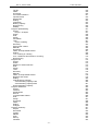
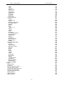
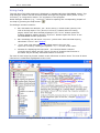
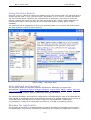
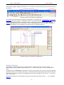

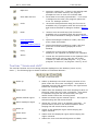

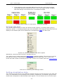
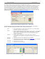


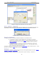

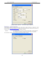
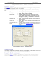
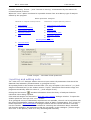
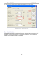
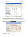
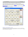


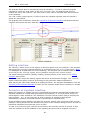
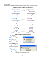
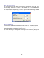
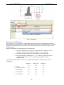
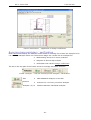


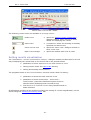
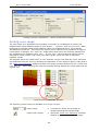


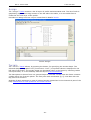
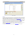
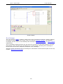
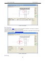

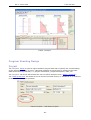


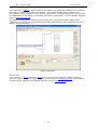

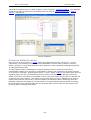

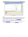
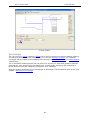
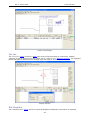

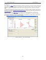
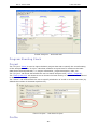
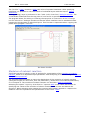

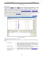


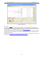

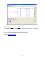


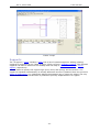
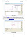
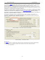
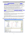

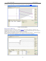
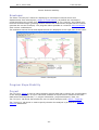
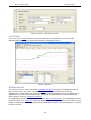

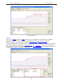


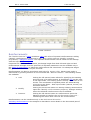
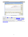

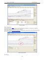


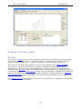
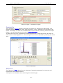
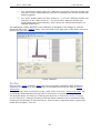
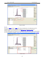
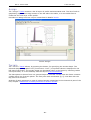


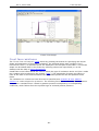

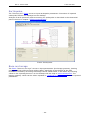


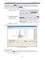


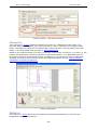

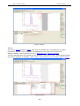
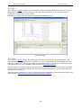


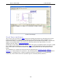
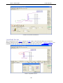
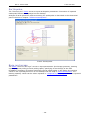


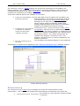

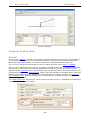

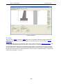
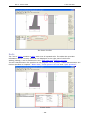
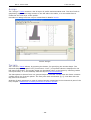
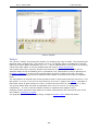
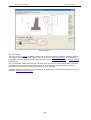
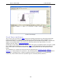
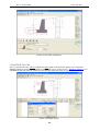
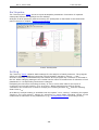
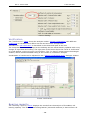

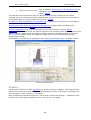


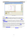
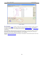


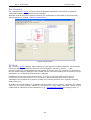
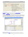
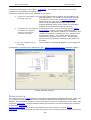
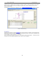

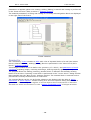
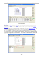
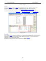
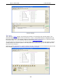

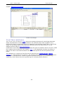
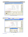


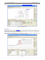
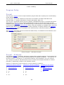

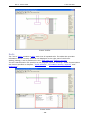
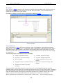
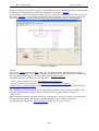

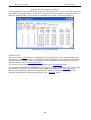


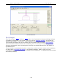


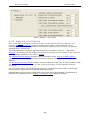


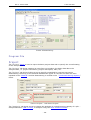

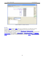


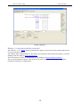
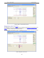


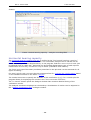
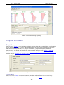
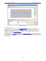

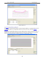
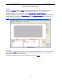


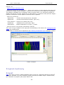


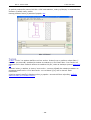

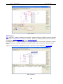
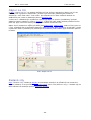
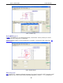
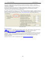

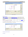

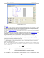
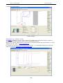
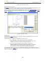
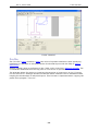


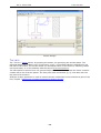
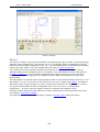
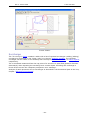


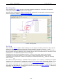
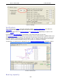


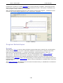
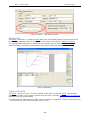
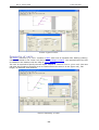


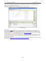
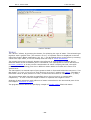
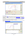
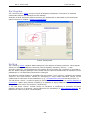
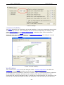
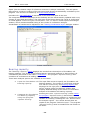
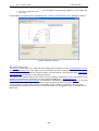


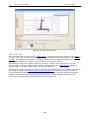
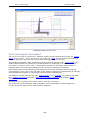
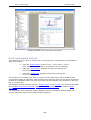


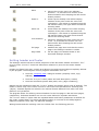
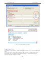

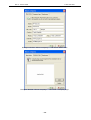
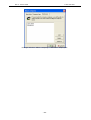


![Fronius String Control 125/25 [42,0410,1572]](http://vs1.manualzilla.com/store/data/006261004_1-244f62dbee49855be39c123844a8e1be-150x150.png)