1
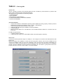
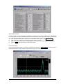
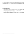
User’s guide
Technical support and product information
http://www.lae-electronic.com/
[email protected]
Page 2
LAE electronic – TAB4.2 - User’s guide
TAB 4.2
- User’s guide
INTRODUCTION
TAB is a software monitoring and supervising plants that are controlled by LAE instruments. It performs data
logging, alarm management and virtual instrument tasks.
The TAB features are described in the following chapters:
1. CONFIGURATION
2. DATA LOGGER
3. DATA DISPLAY AND PRINTOUT
4. ALARM MANAGEMENT and REPORT SENDING
5. VIRTUAL INSTRUMENT
SYSTEM REQUIREMENTS
Computer with Windows Vista/XP/2000 operating system installed and running properly, minimum processor
and memory as required from Windows version – Mouse – CD-ROM drive
at least 640x480 pixels screen resolution; 16-bit colour
at least 500 Mb Hard Disk space available for software installation
1 RS232 serial port
RS232 to RS485 adapter mod. LAE SBC485 or other suitable hardware interface for connection with LAE
instruments.
For SMS message sending:
1 additional RS232 serial port
1 GSM modem (it must be one of the suitable models; consult the supplier of software)
INSTALLATION
Connect the software protection dongle to a ‘USB’ port. If the dongle is not connected, the TAB will perform data
logging only.
Before proceeding to the installation of TAB, close all running tasks. Insert the CD into the CD-ROM drive and
choose the installation option from the menu appearing; if the CD menu does not appear automatically, run
x:\autorun.exe, where x is the drive letter for your CD-ROM drive. Then follow instructions given by the installation
program. After the installation has been performed successfully, the “LAE TAB 4.2” group will be found in the
program start menu; from here, select “TAB 4.2” to start the program.
LAE electronic – TAB4.2 - User’s guide
Page 3
1. CONFIGURATION
When the installation is over, the first operation you have to perform is TAB configuration. To do this, you have to
input the details of the plant to be monitored and the way the various functions, such as data logging or SMS
sending, have to work.
From Main Panel , start the configuration function with Configuration and digit password #1.
As default configuration, after the installation, no password is set; in order to protect the system, it is
necessary to set both passwords #1 and #2.
PASSWORDS
From General Configuration window, it is possible to modify the passwords #1 and #2, which are necessary for
respectively: the first for program configuration and closing, the second for instrument setting. Password #2 is
considered of an upper level compared to the #1 and therefore grants access to all functions. Once the
passwords have been typed and confirmed, they are stored, there’s no need to either save the rest of the
configuration, or restart the TAB.
From General Configuration window, at the top, you must input the plant name, i.e. a description enabling you to
identify the Plant. In this window you can also get the monitored data to be logged in text format automatically, in
such a way that they may be immediately available in Excel or other programs, without the need to get them
exported at a later stage. In order to achieve this, you must tick the box “Text format data logging”. See chapter
“Data Logger” to learn more about this function.
UNITS CONFIGURATION
The plant is a system consisting of several units, refrigeration cabinets/rooms/cases or others, that are individually
controlled by a regulator. You configure the units by assigning, to every connected point, the model of the
controller, its own address and a unit description allowing to unambiguously identify its purpose in the plant. To do
this, it will be helpful to first of all draw up a list of the various items to compile.
Through the suitable switches, enable or exclude the two different monitoring and data logging tasks included in
TAB. These tasks apply to: Defrost Units, a group of units suitable for refrigeration and controlled by specific
defrost regulators (AT1-5, LF28…); Mixed Units, a group including equipment of various nature, controlled by
instruments of different types and with different functions (COPS80, LTC15…).
In order to insert some units in the configuration, it’s necessary to enable the group (ON) and then click on
Defrost Units or Mixed Units.
From Units Configuration window, insert, into every row, unit description (see below “Units identification mode”),
model, peripheral number and, with its switch, enable or inhibit the controller from monitoring tasks. Inhibiting
does not mean removing a controller but that the data read by the TAB (temperatures, alarms, …) are not
processed. This is advisable when a refrigerator or a controller is switched off.
Page 4
LAE electronic – TAB4.2 - User’s guide
You can get the unit rows to scroll within the displayed area, to do this use the cursor located on the right or the
keys Page Up/Page Down of the keyboard.
If you need to remove a unit once for all, it’s necessary to erase all the text in the “Unit” field, then click on Purge.
Whenever you must insert a new unit not at the array end but between two already programmed rows, with the
row-pointer first of all move the insertion point at the window top row, then click on Insert.
From this window it’s also necessary to select the serial port (COM…) used for communication with the units and
the logging rate (5…30 minutes). The logging rate is the saving rate on hard disk of the data read on the enabled
peripherals. When the configuration is over, return to previous window by clicking on Ok.
If necessary, repeat the same operations to configure units in the other group.
Warning: you must set an identification number (peripheral address) to every single instrument
connected to the TAB. You must then also set the same numbers in the TAB configuration window to the
corresponding units appearing in “Defrost Units” and “Mixed Units”. All numbers set must be different
from each other and even different from each group of units (Defrost Units and Mixed Units).
UNIT IDENTIFICATION MODE
In this manual you have an example of how, through a logical unit description, it’s possible to obtain a very
effective representation of the installation.
Considering a typical coolers arrangement in a shop, by using an alphanumeric coding method such as the one
exemplified herein, it’s in fact possible to identify the control unit quickly within all TAB functions. The proposed
method uses as many characters as the physical levels in the plant, with the following rule:
1.1a > Vegetables - UC-65 corresponds to: corridor 1; block of counters 1; unit ‘a’; containing Vegetables;
refrigerated counter model UC-65; controlled by an LDU15 device with address 8.
1.1b > Vegetables - UC-65 corresponds to: corridor 1; block of counters 1; unit ‘b’; containing Vegetables;
refrigerated counter model UC-65; controlled by an LDU15 device with address 1.
2.3a > Frozen Foods - GVA-2 corresponds to: corridor 2; block of counters 3; unit ‘a’; containing Frozen
Foods; freezer model GVA-2; controlled by an LCD32 device with address 14.
You can obviously develop and use your own coding system.
REPORT CONFIGURATION
By clicking on Reports you have got access to the Report configuration window. From here it's possible to
configure if, to whom and when TAB will send SMS reports. For further details on this function, see section “SMS
message transmission”, in chapter “Alarm Management and Sending Reports”.
In "Short Header" input the identification of the calling plant which will appear as header in the SMS messages.
To enable the calls, tick the "SMS report" box and then select the used GSM modem model and the connecting
COM port. It's now possible to set up to 12 receivers and the circumstances under which the report will be sent;
for every receiver, input name, mobile phone number and choose if message sending must be temporarily
disabled (Never), otherwise if it must occur in case of alarm only, or also at the established times (up to twelve) in
"Report Time". If necessary use C to erase the last time set.
LAE electronic – TAB4.2 - User’s guide
Page 5
With OK confirm the data set and return to the General Configuration window.
Now save data with command Save and quit configuration with Exit.
To make the new configuration operative, close TAB and restart it.
To exit from the TAB, press Exit and input password #1.
CONFIGURATION OF A WIRELESS NETWORK
If the controllers present in the plant, or a part of them, must communicate with the TAB through SWB wireless
modules, it’s then necessary to associate the controller peripheral number to the SWB module address to which
the controller is connected. In order to proceed, the wireless network should have already been installed by
following the instructions of the SWB modules and it must be fully active, i.e. both the SWB-C connected to the
computer and all the SWB-R’s connected to the controllers must be switched on.
After saving the plant configuration with Save, click on Wireless Netw.
In the window opening up there is a list of all peripheral numbers given to the controllers of the units added. On
the side of every single controller number that is connected to an SWB wireless module, you must write the 16character address appearing on the external label of the SWB box.
Page 6
LAE electronic – TAB4.2 - User’s guide
In order to avoid writing all individual characters of all addresses present, click on Get addr. List and choose the
COM port to which the SWB-C (network coordinator) is connected. In this way you will obtain a list of addresses
of all the SWB-R’s detected in the network. Now, just click on the arrow on the side of the address field and
choose the right address from the menu.
For those controllers connected to the same SWB-R you must logically choose the same address. For those
controllers which are connected to the PC directly via a hard-wired RS485 line, the field must be left empty.
SETTING ALARM PRIORITY
Clicking on Alarm Setting you have got access to the Alarm Setting window. In order to set the alarm priorities for
an immediate sending of the individual SMS, on the left you find a list of alarm types (all types of alarms of the
LAE instruments available in the TAB) and for each of them you can set a priority.
2. DATA LOGGER
Data logging is the main function of TAB; it starts automatically with TAB if the Units group is enabled. You can
see its on status by the flashing signal in Main Panel. From this window, clicking on Stop and giving password #1
halts the data logger, clicking on Start re-starts it.
Each group “Defrost Units” and “Mixed Units” has got its own task for the display and storage of data.
The windows relating to the two groups show the overall plant state. The displayed data are updated continuously
(with a frequency depending on the number of units fitted) and are also stored permanently with the frequency
selected in the configuration phase.
LAE electronic – TAB4.2 - User’s guide
Page 7
In the windows Defrost Units, dedicated to refrigeration, the program shows Temperature and Defrost, Alarm and
Communication Error States for every single connected unit. You can get the list of units scrolled by means of the
right-hand cursor or, with the keyboard by using the Page UP/DOWN keys.
In the window Mixed Units, the program shows units that are controlled by various types of instruments. The
displayed and stored data depend on the instrument connected: up to two variables (temperature, humidity or
other) and up to three state indicators (alarm, maintenance or other).
TEXT FORMAT DATA LOGGING
If in the General Configuration window the option “Text format data logging” has been enabled, the data logger
records data in text format too. The files generated will be stored in the folder “Datalog”, which is located into the
same folder where the TAB resides. The files have a name consisting of one or more letters that identify the
model of controller followed by 3 figures identifying the address of the device, 2 figures for the month to which
data refer and 2 figures for the year; the extension may be .txt or .xls. You recognise the file relating to a specific
unit in the plant by the device number (address).
Warning: those files are formatted in such a way as that you will be able to open them from Excel (.xls) or
other applications directly. Yet, in order to allow the files to be updated, it’s mandatory to first copy the
Page 8
LAE electronic – TAB4.2 - User’s guide
file, preferably into another folder, and then you work on the copy made. When the TAB has to update a
data file, if this file is already open data will be saved into a file with the same name plus “_m” at the end, so that
no data will be lost. Please take into account that the “reference” data are always those that are saved in the TAB
format, and that can always be retrieved and analysed with the TAB tools and if necessary exported in text
format.
3. DATA DISPLAY AND PRINTOUT
From Main Panel by clicking on Defrost Units or Mixed Units within “Data Retrieve” area, you get access to the
retrieve, display and printout of the data stored by the data logger.
It’s first of all necessary to choose the unit in the plant of which you wish to retrieve data and set the start and end
time & date of the period you are interested in. Then click on Load to retrieve data.
To set date and time, press the little button close to the relevant boxes, a window will appear where it will be easy
to choose day, month, year and time.
If you want to retrieve the data of a unit no longer present in the configuration, choose “free device Model - No.”
from the units list and then input model and device number.
After data have been loaded, they can be displayed in a graph format or alternatively in a table format by pressing
button Table. If you choose a graph, the curves representing a value refer to the scale on the left, while those
representing an on/off state refer to scale on the right (0=off , 1=on); scales can be modified, for an easier data
consultation, by clicking on the highest or lowest scale values and by giving new limits.
By clicking on the right hand legend, you can modify the outlook of the various curves.
Moreover, several graph analysis tools are available, such as zooming or the cursor, as well as several curve or
scale customisation options.
LAE electronic – TAB4.2 - User’s guide
Page 9
Cursor Value
Cursor Time
Cursor Name
Scale settings
Zoom and panning
Cursor movement enabling
Cursor display mode
Lock control
Cursor movement
By clicking on Export, the loaded data can be saved in a text format readable from Excel or other spreadsheets
programs; the data that will be exported are those of the period that you select and load and are the same as
those appearing in the table representation. Following zooming or scale modification, the graph might include just
part of them.
The displayed data can be printed by clicking on Print; the printout will either show the table or the graph
depending on what is on the screen at that specific moment. In case of graph printout, a preview window opens
up, from which you can again choose the type of line, colour and other features of the curves in such a way as to
obtain the best result according to the type of printer used (for example, although it’s always preferable to use a
colour printer, if you have a monochromatic printer you can have the various curves distinguished by choosing
dotted lines).
The printouts will always be sent to the default printer.
4. ALARM MANAGEMENT AND REPORT SENDING
As described in chapter 1, from General Configuration you can enable the tasks relating to a group of units;
among these tasks there is monitoring and storage of the alarms that occurred in the peripherals.
The alarm situation is displayed in the Alarm List window. It shows the recent alarm history by reporting alarm
starting time, its source, the unit where it took place and, its priority, whenever the alarm is over, its ending time.
In addition, on the left of every event a red light signals that the alarm is still on, and it turns green when the alarm
is over. The lighting up of the “New Alarm” indicator means that new alarms took place since the last
acknowledgement.
Page 10
LAE electronic – TAB4.2 - User’s guide
Whenever in a controller an alarm condition occurs, it is read and stored by TAB. At the same time, regardless of
the window you are working in, a red “Alarm” window comes up, showing a plant anomaly. Now, clicking on
“Alarm” or on Alarm List in Main panel opens Alarm list window.
After you have become aware of the situation, you can switch off the “New Alarm” indicator and remove the
already ended alarms from the list (they will however remain stored on file) by clicking on Acknowledge.
All alarms are stored on hard disk and displayed or printed out from the Alarm History window, which is opened
by clicking on History. In this window, you must choose the month concerned, load the data and if necessary then
print out on the default device by clicking on Print.
The inhibited units are excluded from alarm management.
In Alarm History also the field Date/Time of event end is stored; this data is therefore saved when the event is
over.
SMS MESSAGE TRANSMISSION
TAB incorporates the SMS message sending function, in order to constantly keep one or more people informed
on the proper plant operation and, in case of alarms, inform them promptly.
As a matter of fact the messages can either be sent in case of an alarm or even at programmed times. In the
Report configuration window you can choose if and when alarms are sent according to the following options:
Never, temporarily excluded; Alarm, only when alarms occur; Alarm and Time, therefore when alarms occur or
however at the times set into the "Report Time" boxes.
The alarm condition for the immediate sending must consist of one or more new alarms, with priority greater than
or equal to the minimum priority set in the Alarms Setting window, detected in one or more units. In the event that
the message is sent at a set time, it will report that there are alarms, even not new ones and with priority lower
than the minimum priority set, in one or more units or, if no alarm is on, it will indicate that no alarm is going on. In
this latter case, the enabled receiver will however be informed about the correct operation of the whole system.
Differently, if the set message is not received at the due time, this will mean that a failure in any of the vital parts
of the system occurred (PC, modem, etc.).
In case of alarms with priority great enough for the immediate sending of the SMS report, at the end of the event a
end of alarm message is sent, with the indication of all ended events.
If the length of the SMS is greater than 160 characters, a series of linked messages will be sent out according to
the ETSI GSM 03.40 specifications. Usually, the receiving device will be able to link all elements together.
The sent message includes the following information:
Short Header, Date and Time, list of the units where alarms took place with alarm type (if none, "No Alarms").
In order to identify the unit, the first 60 characters of the given description are used.
The use of the GSM modem allows an alarm report to be sent not only automatically but also as a reply to an
occasional request by any GSM mobile phone. To achieve this it’s necessary to send a message like the following
to the modem telephone number: R[receiver’s number]:[required function].
As an example: R+391231234567: LCR
LAE electronic – TAB4.2 - User’s guide
Page 11
The report request message sent to the TAB may also omit the receiver’s number of the report (R:LCR); in this
case the report will be sent to the sender of the request.
Presently the only supported function is LCR (Last Check Report), which requires a report on the alarms, just like
the report that is sent automatically at set times.
If SMS report sending has been enabled, when the TAB is started a window comes on, allowing you to easily
check on the receivers and when messages are sent; you can also have direct access to the relevant settings
through the button Modify.
5. VIRTUAL INSTRUMENT
With this function you can check the state and the dynamical data of the connected devices but you can also
change the control parameters. From Main Panel, by clicking on Defrost Units or Mixed Units within “Virtual
Instrument” area, you can choose the group of units on which you wish to operate.
CONNECTION WITH A PERIPHERAL
Initially, in the Virtual Instrument window appears you must choose with “Unit” the peripheral you are interested in.
Once that data communication is on, the dynamic data of the controller, like temperatures, alarm, defrost, standby etc. are displayed on the monitor. Differently, if the comm.error indicator lights up, this means that the
connection with a peripheral did not take place. In this case, check on the network and the configuration.
To get access to the parameter display and programming window, you must first click on Device Settings then
you’ve got to enter password # 2. If a password was set but you don’t enter it, you will always have access to the
parameter window but you will have no chance to modify the parameters.
The values presently set on the controller are read and displayed automatically when the window is opened. You
may read them at a later stage again by clicking on Read
Parameters may be set in two different ways: using values previously stored in the files related to a specific model
or choosing the data to set one by one. In the first case, click on Load to read a default-programming mask
among the files stored with Save. For manual parameter modification, first of all with select the data to change,
then modify the value by using: left sided v, numeric keypad / arrows, pull-down menu if present, or by
numerically typing the new value. In this latter case, confirm the new data with .
After performing all modifications, click on Write to send the ticked off values only ( ) to the device.
Page 12
LAE electronic – TAB4.2 - User’s guide
SETUP LIBRARY CREATION
In order to speed up routine programming operations, it’s possible to store a series of setup files on hard disk that
can include all or part of the configuration parameters of every device model. Such files will build a quick access
library ensuring safe programming. To create a file, you must proceed in the following way:
A.
Open the window relating to the device you are interested in (LF28, LTC15, …) via Device Settings.
B.
With select all or part of the parameters and assign them a new value.
C.
Write your comment on the top row. This description can help you understand the purpose of that setup.
D.
Click on Save and choose folder and name of the new file.
LATEST HOURS TREND
From Virtual Instrument window, by selecting a peripheral and clicking on Latest h. trend you promptly obtain a
graphic representation of all its analogic inputs stored during the last 24 hours.
LAE electronic – TAB4.2 - User’s guide
Page 13
This function offers a valid tool for diagnostics purposes or to adjust the unit setup parameters to improve
controller performance.
As per the historical graphs, tools such as zooming, panning, cursors and several different curve outlook
customisation tools are available for an ideal data consultation.
Troubleshooting
The comm.error indicator remains red
1. Check that the SBC485 is powered correctly (on LED lit).
2. If the on LED is lit but the other LED’s of the SBC485 never light up, check that the selected PC COM
port actually corresponds to the one connected to the SBC485, that it’s not used for other tasks, that the
cable is correct (of the type used for the modems, with RX RX TX TX straight connections).
3. If the yellow LED only never lights up, check the device connections (the signals A and B of the RS-485
line could be inverted) and the address on TAB and peripheral.
The messages within the windows are confused or superposed
If the monitor resolution is set at 800x600 or higher, from “Display properties” click on “Settings” tab and
choose “Small Fonts” from Font Size of Windows configuration panel.
Designed with LabVIEW , copyright 2008 of National Instruments Corporation. All rights reserved.
The above mentioned trademarks are property of the respective holders.
Page 14
LAE electronic – TAB4.2 - User’s guide