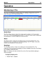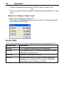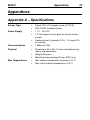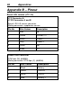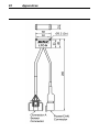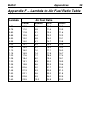
1
MoTeC LTC User Manual Contents Introduction .............................................................................. 2 Installation ................................................................................ 4 LTC Installation ..................................................................................... 4 Lambda Sensor Installation .................................................................. 4 LTC Manager Software Installation ...................................................... 6 Configuration ........................................................................... 8 Introduction ........................................................................................... 8 Setup..................................................................................................... 8 Calibration ........................................................................................... 13 Firmware ............................................................................................. 16 Operation ................................................................................ 17 Monitoring LTCs ................................................................................. 17 MoTeC Data Loggers ......................................................................... 20 MoTeC 'Hundred Series' ECUs .......................................................... 21 Lambda and Air Fuel Ratio ................................................................. 24 LTC Operating Tips ............................................................................ 26 Appendices ............................................................................ 27 Appendix A – Specifications ............................................................... 27 Appendix B – Pinout ........................................................................... 28 Appendix C – Dimensions .................................................................. 30 Appendix D – Wiring Details ............................................................... 33 Appendix E – LTC CAN Messages..................................................... 36 Appendix F – Lambda to Air Fuel Ratio Table .................................... 39 Copyright 2011 – MoTeC Pty Ltd The information in this document is subject to change without notice. While every effort is taken to ensure correctness, no responsibility will be taken for the consequences of any inaccuracies or omissions in this manual. V1.5 15 September 2011 2 Introduction Introduction MoTeC LTCs (Lambda to CAN) monitor and control Wideband Lambda sensors and transmit Lambda readings and diagnostics on a CAN bus. There are single channel LTC and Dual channel LTCD available to suit either Bosch LSU4.9 or NTK sensors: • #61300 – Single channel Bosch LSU 4.9 Sensor • #61301 – Dual Channel Bosch LSU 4.9 Sensors • #61304 – Single Channel NTK Sensor • #61305 – Dual Channel NTK Sensors Up to 32 Lambda sensors can be configured on a single CAN bus using LTCs, allowing an ECU or Data Logger to simultaneously monitor multiple Lambda sensors. Throughout this manual the LTC, LTCD, LTC-N and LTCD-N will be referred to as LTC except where details specific to a particular model are discussed. Features • Accurate Lambda measurement even when the exhaust gas temperature is changing rapidly (heating or cooling) • Ability to perform free air sensor calibration or use the initial sensor factory calibration. LTC-N has the ability to be calibrated against a test gas. • Pre-configured to work in a single LTC or LTCD installation, without requiring configuration with a PC • LTC Manager software to: o configure and calibrate all LTCs on the CAN bus o display readings and diagnostics o configure the CAN transmission address of each LTC o control free air calibration o update LTC firmware Compatibility • MoTeC ‘Hundred series’ ECUs: M400, M600, M800 and M880 • MoTeC M1 Series ECUs • MoTeC Data Loggers : SDL, SDL3, ADL, ADL2, ADL3, ACL MoTeC Introduction Accessories • #57006 Bosch LSU 4.9 Lambda Sensor • #57007 NTK Lambda Sensor • #61059 MoTeC UTC - USB to CAN, used to communicate to the PC (optional) Note: LTC is not compatible with MoTeC's CAN cable (part number 61021) 3 4 Installation Installation LTC Installation The LTC can be mounted to a flat surface using the two mounting holes. The LTC should be mounted as far as possible from the exhaust to avoid excessive heat. Note: LTC maximum ambient temperature is 100 °C. Use Connector A to connect the single LTC to the Lambda sensor. Use connectors A and B to connect the LTCD to two Lambda sensors. Use the Power/CAN Connector to power the LTC and connect to the CAN bus. See Appendices for more details. Lambda Sensor Installation Warning: The Bosch LSU 4.9 Lambda sensors are fitted from the factory with a calibrated trimming resistor embedded in the sensor connector. If the factory sensor connector is cut off and replaced with another type, the LTC will not operate correctly. Note: Unlike the Bosch LSU 4.9 the NTK sensors standard connector can be removed and replaced by a non-standard connector without affecting the performance of the sensor or the LTC-N. However, the initial factory calibration method will not work as the calibration resistor is built into the original connector. In this case Free Air calibration is required. It is recommended that no wiring modification is made to the NTK sensor or LTC-N unless completely necessary. The Lambda sensor should be fitted to the exhaust system with the sensor tip protruding into the exhaust gas flow. The following considerations should be taken into account when fitting the sensor: • Place the sensor on an angle between 10 and 90 degrees to the vertical with the tip of the sensor pointing down to prevent condensation build up between the sensor case and the sensor ceramic. • Do not place the sensor in a vertical position; excess heat soak will prevent proper operation. • Place the sensor at least 1 meter from the exhaust ports to avoid excessive heat (recommended). MoTeC Installation 5 • Place the sensor at least 1 meter from the open end of the exhaust system to avoid incorrect readings due to outside oxygen (recommended) o Where necessary for shorter exhaust systems the sensor could be placed closer to the engine. • Place the sensor away from the flame front coming out of the cylinder head and away from areas where one cylinder may have more effect than another. Correct sensor placement Incorrect sensor placement • If possible, do not place the sensor near exhaust slip joints; some designs allow air to enter resulting in incorrect readings. If the sensor has to be placed near a slip joint, reverse the slip joints to reduce the influence of introduced air. Introduced air No air introduced Exhaust flow Exhaust slip joint design 6 Installation LTC Manager Software Installation The LTC Manager software is required for configuration and calibration of LTC units. The software must be installed on Windows XP or Windows Vista. The same software package is used for the LTC, LTCD, LTC-N and LTCD-N. Note: The LTC Manager software is not required if using a single LTC or LTCD unit preconfigured by MoTeC. MoTeC Installation 7 Install LTC Manager Software • Go to the MoTeC website at www.motec.com and navigate to downloads > software > latest releases > LTC Manager OR Locate LTC Manager installation file on the MoTeC Resource Disc • Save the LTC Manager installation file in your preferred location (for example desktop) • Double click the saved file to run the installer • Follow the installation instructions on the Install Shield Wizard • To start the program after installation, double click the LTC Manager icon on the desktop OR Click Start > All Programs > MoTeC > LTC > LTC Manager Updating Software Software updates are available free of charge, giving access to the latest features for the life of the device. Download the latest software versions from the website and follow the software installation instructions to update to the new version. To update the associated firmware in the device see Firmware. 8 Configuration Configuration Introduction Note: LTC units come pre-configured to suit a single LTC or LTCD unit installation using the initial factory sensor calibration. The default CAN address for the singular LTC is hex 460. The default CAN addresses for LTCD is hex 460 for Lambda sensor 1 and hex 461 for Lambda sensor 2. LTC Manager is used to individually configure and calibrate the connected LTC units. Configuration using LTC Manager is only necessary if installing multiple LTC units or if changes to the default settings are required. All LTC configuration and calibration operations are performed directly on an LTC and configurations are not stored on disk. Start LTC Configuration • Connect the unit to the PC (see Appendix D – Wiring Details) • Ensure the unit is powered Start LTC Manager o Click the LTC Manager icon on the desktop OR o Click Start > All Programs > MoTeC > LTC > LTC Manager. The main LTC Manager window displays the live configuration and status of all LTC units present on the connected CAN bus. • Setup CAN Address The CAN setup determines which CAN address (specified in hex) the LTC uses to transmit readings and diagnostic information. The format of the CAN messages is described in. Appendix E – LTC CAN Messages Each LTC on a CAN bus must be configured with a unique CAN address. See Operation for information on configuring a MoTeC Data Logger or ECU to receive LTC CAN messages. MoTeC Configuration 9 LTC Unit Setup • To open the LTC Setup window, double click the row in the table containing the LTC or click the row and click Setup. • Select the Recommended Address check box and enter one of the addresses in the drop down box to communicate with MoTeC products such as Data Loggers or 'hundred series' ECUs. The recommended address range for LTC messages is hex 460 to hex 47F. OR Select the Custom Address check box and enter an address (in hex) for interfacing with third party equipment. OR Select Disabled to prevent an LTC from transmitting CAN messages. While disabled an LTC will not heat the sensor or perform Lambda measurements. Note: Lambda sensors should not be left in the exhaust system of a running engine if they are not being controlled. A disabled sensor in a running engine can be damaged. • In the Name area the default name will appear. The default name matches the selected CAN Address (LTC1 etc.). If required the user can specify a custom name (e.g. Left Bank or Cylinder 4). Tip: The rows in the main LTC Manager window are sorted by the Name column. 10 • Configuration Click OK. The configuration updates will be sent to the LTC, this may take several seconds LTC-N Unit Setup • To open the LTC Setup window, double click the row in the table containing the LTC or click the row and click Setup. • Select the Recommended Address check box and enter one of the addresses in the drop down box to communicate with MoTeC products such as Data Loggers or 'hundred series' ECUs. The recommended address range for LTC messages is hex 460 to hex 47F. OR Select the Custom Address check box and enter an address (in hex) for interfacing with third party equipment. OR Select Disabled to prevent an LTC from transmitting CAN messages. While disabled an LTC will not heat the sensor or perform Lambda measurements. MoTeC Configuration 11 Note: Lambda sensors should not be left in the exhaust system of a running engine if they are not being controlled. A disabled sensor in a running engine can be damaged. • • In the Name area the default name will appear. The default name matches the selected CAN Address (LTC1 etc.). If required the user can specify a custom name (e.g. Left Bank or Cylinder 4). Tip: The rows in the main LTC Manager window are sorted by the Name column. Select a Standard Sensor type from the drop down menu OR Select a Custom Sensor Note: Custom sensor setups are for advanced users and it is not recommended for general use. • Select a Standard Output Table, generally Lambda to three decimal places OR Use a Custom Table for another type of fuel, e.g. Diesel. • Click OK. The configuration updates will be sent to the LTC, this may take several seconds LTC-N Output Table The standard output table for the LTC-N is for Lambda to three decimal places. It is possible for the user to make a custom table to suit the Air/Fuel ratio of any fuel. 12 Configuration When the Edit button is clicked under Output Table a table of Normalized Current appears. The standard Lambda values appear in the Output column, these numbers can be modified to reflect Air/Fuel ratio of a specific fuel. See Appendix F for details of common fuels. Custom tables can be saved using the Save As button. CAN Collect Functionality CAN Collect functionality allows one LTC (the CAN Collect Master) to collect CAN data from up to 15 other slave LTCs, and retransmit these Lambda readings on a single CAN address (see Appendix E – LTC CAN Messages). Note: A CAN Collect Master device will continue to transmit the standard LTC messages in addition to the special collect master messages. CAN Collect functionality requires only a single CAN address to be configured on a MoTeC Data Logger to receive up to 16 Lambda readings. See Operation for information on configuring MoTeC Data Loggers or ECUs to use CAN Collect. Configure Master and Slave Units • To configure an LTC as the CAN Collect Master device, select the CAN Collect Master check box and select a CAN address. The CAN address for the Master device is the address on which the collected Lambda values will be retransmitted. This address must end in a zero (i.e. hex 460, 470 etc). The recommended address is hex 460. • To configure an LTC as a CAN Collect Slave device, clear the CAN Collect Master check box and select a CAN address. The CAN address for a Slave device must be configured with one of the 15 addresses following the master address. For example, if the collect master MoTeC Configuration 13 address is hex 460, the slave devices must use CAN addresses in the range hex 461 to 46F. The Collect column on the main LTC Manager Window shows the configuration of CAN Collect Masters and Slaves. The Master device is always shown as LTC unit 1 (Master (1)), and the slave devices are shown as LTC units 2 to 16 according to the configured CAN address as shown in this example. Calibration Warning: The Bosch LSU 4.9 Lambda sensors are fitted from factory with a calibrated trimming resistor embedded in the sensor connector, if the factory sensor connector is cut off and replaced with another type the LTC will not operate correctly. Note: Unlike the Bosch LSU 4.9 the NTK sensors standard connector can be removed and replaced by a non-standard connector without affecting the performance of the sensor or the LTC-N. However, the initial factory calibration method will not work as the calibration resistor is built into the original connector. In this case Free Air calibration is required. It is recommended that no wiring modification is made to the NTK sensor or LTC-N unless completely necessary. Calibration Methods Initial factory calibration The default calibration method uses the known characteristics of a new sensor that has been factory trimmed. Free Air Calibration As a sensor ages, the sensor calibration may change. To maintain accurate readings, the LTC allows for re-calibration using the known oxygen concentration of free air. The free air calibration procedure takes several readings with the sensor in free air to calculate new calibration values. To perform an accurate free air calibration, the lambda sensor must be removed from the exhaust and placed in an open air environment. It is recommended to perform the calibration outside of a workshop or dyno room as there may be large amounts of hydrocarbons in the atmosphere. 14 Configuration Contaminated air will result in an incorrect calibration or a failure to calibrate. Wind should also be avoided as it can affect the free air calibration. Reference Gas Calibration Reference gas samples for different lambda can be purchased (not available from MoTeC) for use as a means of calibrating the LTC. This method is provided for but is unlikely to be implemented by most users. Calibrate the LTC Unit • Click Calibrate… to open the Gain Calibration window • Select one of the three options available. o Select the Initial Factory Sensor Calibration check box. This is the default value and can be used in most cases. OR Select the Entered Free Air Calibration check box and enter the values in the boxes if a previous free air calibration value is known, OR Select the Free Air Calibration check box to perform a new calibration. − − − − Click Perform Air Calibration Note: The calibration process may take several minutes during which the calibration progress window is displayed. When the message Calibration completed appears click OK The new calibration value is displayed. This value should be recorded against the serial number of the sensor to enter this calibration when the sensor is used with another LTC unit. To apply the new calibration click OK. • Click OK to save the calibration method and settings to the LTC. Tip: Spare sensors can be air calibrated before an event and tagged with the 14 digit calibration number. This number can be used in the entered Free Air Calibration option for quick replacement of a sensor during the event. MoTeC Configuration 15 Calibrate the LTC-N Unit • Click Calibrate… to open the Gain Calibration window • Select one of the four options available. o Select the Initial Factory Sensor Calibration check box. This is the default value and can be used in most cases. OR Select the Entered Gain Factor from a previous Free Air Calibration or Reference Gas Calibration OR Select the Free Air Calibration check box to perform a new calibration. Click Perform Air Calibration Note: The calibration process may take several minutes during which the calibration progress window is displayed. − When the message Calibration completed appears click OK − The new calibration value is displayed. This value should be recorded against the serial number of the sensor to enter this calibration when the sensor is used with another LTC unit. − To apply the new calibration click OK. OR Select the Reference Gas Calibration. − Note: A Reference Gas Calibration is not recommended for normal use as it required calibrated testing gas. • Click OK to save the calibration method and settings to the LTC. Tip: Spare sensors can be air calibrated before an event and tagged with the 4 digit calibration number. This number can be used in the Entered Gain Factor calibration option for quick replacement of a sensor during the event. 16 Configuration Firmware Each version of the LTC Manager software includes a matching firmware version that must be sent to the LTC in order to operate correctly. The Config Status column in the main LTC Manager window will indicate if the firmware version requires updating. Update the Firmware • Select the LTC row in the main LTC Manager window • Click Update Firmware. A progress window will be displayed while the firmware is sent to the LTC. MoTeC Operation 17 Operation Monitoring LTCs The main LTC Manager window shows live readings, diagnostics and LTC state information for all connected LTCs. Serial Num The Serial Num column shows the unique serial numbers of all connected LTCs. An LTCD will be displayed as two LTCs with the same serial number but the designators A and B to identify the two sensors. Name The Name column shows the assigned names of all connected LTCs. The displayed name is configured in the Setup dialog. The LTC rows in the main screen are sorted by the name column. Readings The Readings column shows live readings of all connected LTCs. The readings can be configured to display as either Lambda or AFR (Air Fuel Ratio) for a number of different fuels. Note: the display units do not affect the units of the transmitted readings in CAN messages. Configure display units • Select Tools > Options. 18 Operation • Choose a predefined stoichiometric AFR for one of various fuels OR Define a custom AFR by entering a stoichiometric point between 1.0 and 100.0. Display live readings in larger format • Select View > Readings or press F5. This larger format display provides a useful means of monitoring several sensor values while tuning. Sensor State The Sensor State column shows the operating state of all connected LTCs. Sensor State Description Starting LTC hardware is performing a self calibration Heating The Lambda sensor is outside the temperature range required for measurement Running Lambda measurement is active Cooling A heater short circuit or a failure to reach operating temperature has occurred. The sensor is allowed to cool before another attempt at heating. MoTeC Operation 19 Diagnostics The Diagnostics column shows faults and diagnostic information for all connected LTCs. Diagnostic Description Heater short circuit (GND) A short circuit to ground has been detected in the heater wiring Heater short circuit (Batt+) A short circuit to battery+ has been detected in the heater wiring Heater open circuit An open circuit has been detected in the heater wiring Failed to achieve heat The measured sensor temperature is not responding to sensor heating. This fault may indicate a fault with the sensor wiring. Sensor short circuit A short circuit has been detected in the sensor wiring Corrupt Firmware The LTC firmware is corrupt. Upgrade the firmware to restore operation. Incompatible Firmware The LTC firmware is incompatible with LTC Manager. Upgrade the firmware to restore operation. LTC Temp The LTC Temp column shows live internal temperature readings of all connected LTCs. Note: The temperature column shows the temperature of the LTC unit, not the sensor temperature. CAN Address The CAN Address column shows the configured CAN addresses (in hex) of all connected LTCs. To configure the CAN addresses see Setup. Collect The Collect column shows the configured CAN Collect functionality of all connected LTCs. To configure the CAN Collect functionality see Setup. A configured CAN Collect Master device is always shown as Master (1). 20 Operation Any LTC unit configured with a CAN address within the 15 CAN addresses following a Collect Master address will be shown as Slave (x). The number in the collect column (e.g. (3)) refers to the LTC number (1 to 16) in the messages transmitted by a Collect Master LTC. For more information about CAN Collect, see CAN Collect Functionality Config Status The Config Status column shows any issues relating to the configuration of the connected LTCs. Config Status Description OK Config is OK Disabled The LTC has been disabled under the Setup options. A disabled LTC will not measure or transmit readings. Incompatible Config The configuration in the LTC is not compatible with the firmware in the LTC. A new configuration can be sent to the LTC by changing the Setup or Calibration. Corrupt Config The configuration in the LTC is corrupt. A new configuration can be sent to the LTC by changing the Setup or Calibration. CAN Address Conflict Multiple LTC units have been configured with the same CAN address. Each LTC must be configured with a unique address. Firmware Version The Firmware Version column shows the version of the firmware in each of the connected LTCs. MoTeC Data Loggers MoTeC Data Loggers SDL, SDL2, ADL2, ADL3 and ACL include CAN communication templates to receive LTC messages from up to 16 LTCs. Received Lambda readings and diagnostics can be displayed and logged. Refer to the Dash Manager software for more information. Configure Data Logger Communications for LTC: • Select Inputs > Communications MoTeC Operation 21 • Click on an unused CAN row in the Communication Sections • Click Select button and choose a template o o Select the matching template (e.g. LTC #1 (CAN ID 460)) to receive all available readings and diagnostics from an LTC. The selected template must match the LTC CAN address specified in LTC Manager. Receiving full LTC messages provides the most information about an LTC and requires one CAN section per LTC in the communications setup. Select the LTC Collect 16 Channel CAN template to receive Lambda readings from up to 16 LTCs. The LTCs must be configured in LTC Manager for CAN Collect functionality using address hex 460 for the CAN Collect Master. Receiving CAN collect messages provides only Lambda readings from each LTC and only requires one CAN section in the communications setup for up to 16 Lambda readings. For more information see CAN Collect Functionality. MoTeC 'Hundred Series' ECUs MoTeC ‘Hundred Series’ ECUs (M400, M600, M800, M880) can be configured to receive Lambda measurements from up to 12 LTCs using the existing PLM CAN templates in the ECU Manager software. The M84 ECU can receive two channels of Lambda with CAN addresses 460 and 461. Received Lambda readings can be used in engine control and logged. Refer to the ECU Manager software for more information. Note: The ECU only stores the Lambda readings from the LTC messages; LTC diagnostic information is not stored. Configure Hundred Series ECU Communications for LTC • Select Adjust > General Setup > Communication > CAN Setup • For single LTC configuration: o Select a spare CAN data slot in the range CAN 1 to CAN 6 o Enter 1 - PLM Receive for CAN Data Enter the LTC CAN Address in decimal*. The address must match the CAN address specified in LTC Manager. • For CAN Collect configuration: The LTCs must be configured in LTC Manager for CAN Collect functionality using address hex 460 for the CAN Collect Master. 22 Operation Enter 1 - PLM Receive for CAN 6 Data Enter the LTC CAN address in decimal* for CAN 6 address. The address must match the CAN address specified in LTC Manager for the CAN Collect Master LTC. The recommended address is 1120. * Important: CAN addresses in ECU Manager are in decimal, while the CAN addresses in LTC Manager are in hex. e.g. 1120 decimal = 460 hex o o Configure M84 ECU Communications for LTC • Select Adjust > General Setup > Communication > CAN Setup • For single or dual LTC configuration: o Enter a CAN Address of 1120 (460 Hex) into the PLM CAN Address Assign Lambda measurements to a Hundred Series channel Lambda measurements from the LTCs must be assigned to an ECU channel before they can be used for engine control or logging. • Select Adjust > Sensor Setup > Input Setup... to open the Input Pins Setup dialog. • Attach an LTC reading to a channel, using the following parameters Input Source Predefined Calibration PLM 1 to PLM 12 #81 Lambda: PLM over CAN Example 1: LTC1 reading assigned to channel Lambda 1 MoTeC Operation 23 Example 2: LTC1 to LTC4 readings assigned to Lambda Cyl channels Assign Lambda measurements to a M84 channel For an M84 the Lambda Input Source is fixed so only the Calibration needs to be chosen – Predefined “#81 Lambda: PLM over CAN” 24 Operation Lambda and Air Fuel Ratio Lambda gives a measure of the Air to Fuel Ratio (AFR) that is independent of the type of fuel being used. Lambda 1.00 Stoichiometric ratio: no excess fuel and no excess air Lambda > 1.00 Lean: excess air Lambda < 1.00 Rich: excess fuel Stoichiometric Air Fuel Ratio for various fuels Lambda 1.0 Air Fuel Ratio Petrol Alcohol LPG Diesel 14.7 6.4 15.5 14.5 Calculations with Lambda Fuel Stoichiometric AFR Measured value Calculated value Petrol 14.7 AFR = 14 Lambda = 14/14.7 = 0.95 Diesel 14.5 Lambda = 1.1 AFR = 1.1 x 14.5 = 16 See Appendix F – Lambda to Air Fuel Ratio Table for a quick reference table. Engine Tuning with Lambda When tuning the engine, the target Lambda (or AFR) is dependent on the tuning objective. The following table can be used as a guideline. Tuning objective Lambda Maximum power 0.84 to 0.90 Economy 1.05 Emissions 1.00 Normally the engine is tuned for maximum power at full load and for emissions or economy at light loads. The exact requirements for a specific engine and fuel can only be found by experimentation. On turbo engines extra fuel may be desirable to reduce exhaust temperatures and help avoid knock. If the vehicle is fitted with a catalytic converter, extra fuel may be required to ensure the catalyst does not overheat when not operating at Lambda 1.00 MoTeC Operation 25 Lambda Sensor Sensor Warm-up The internal heater in the Lambda sensor is powerful enough to allow accurate measurement when gas temperature is at room temperature. The sensor will take approximately 20 seconds to heat up. The maximum continuous operating temperature of the sensor is 850 °C. Sensors should not be used at higher temperatures for a prolonged period, although the sensor can be heated to 930 °C for a maximum of 10 minutes. This may however reduce the accuracy. Sensor Lifetime The sensor lifetime is dependent on the type of fuel being used and the volume of gas flow over the sensor. Sensor lifetime will be reduced by contaminants such as silicon, lead, oil, etc. Thermal cycling and exposure to exhaust fumes without any heating control active will also age the sensor more rapidly. Manifold sealants can contaminate sensors. Use sealants that are sensorfriendly to prevent reduced sensor lifetime. When using leaded fuel, sensor element contamination will reduce the sensor lifetime substantially. Typically sensor lifetime for high performance engines is at least 500 hours in unleaded fuel and 50 hours in leaded fuel. Longer lifetimes can be expected for less demanding applications. These figures are a conservative estimate as the sensors are designed to be accurate for 50,000 km of operation in a road car. Incorrect placement in the exhaust can overheat the sensor and significantly reduce the sensor life. For the Bosch LSU 4.9 the sensor impedance (Ri) is an indication of sensor temperature. In normal operation Ri should be approximately 300 ohms. If Ri is less than 250 ohms then the sensor is being overheated. Ri is included in the transmitted CAN messages. Due to the different control system for the NTK sensor the Ri parameter is not applicable. At the end of its life the sensor becomes slow to respond and does not read rich properly. Regular performance of the Free Air Calibration (see Calibration) will maintain the accuracy of the sensor over its lifetime. 26 Operation LTC Operating Tips If the engine misfires for any reason, including an over-rich mixture, the LTC may falsely read Lean. This is due to excess air being present in the exhaust gasses, caused by incomplete combustion. Other areas that can give misleading readings include at high RPM, closed throttle when the mixture won’t burn completely. Following overrun fuel cut when the sensor has become saturated with oxygen it can take up to several seconds to resume accurate readings. Engine misfires include hitting the revlimiter, be it a fuel or ignition cut or a combination of both, and can give a similar result with time being required to purge the sensor of excess oxygen or fuel. Engines with high overlap camshafts running at low speed may pump air through the engine resulting in a false lean reading, Therefore the LTC may need to read leaner than would otherwise be expected. MoTeC Appendices 27 Appendices Appendix A – Specifications Sensor Type • • NTK LZA09 Lambda Sensor Power Supply • 11 V - 16 V DC • 110 mA typical current plus the sensor heater current. • Heater current is typically 0.5 A - 1 A (up to 2 A on startup) Communications • 1 Mbit/sec CAN Physical • Dimensions 38 x 26 x 14 mm excluding wiring looms and connectors • Weight 62 grams • Mounting holes spacing 32 mm (Ø3.2 mm) • Max ambient temperature at device 100 °C • Max internal device temperature 125 °C Max Temperatures Bosch LSU 4.9 Lambda sensor (LTC4.9) 28 Appendices Appendix B – Pinout Bosch LSU version (LTC 4.9) LTC Connector A LTCD Connector A and B Bosch LSU 4.9 sensor connector Mating connector: supplied on sensor Pin No Wire Colour Description 1 Red Ip 2 Yellow Sensor 0 V 3 White Heater - 4 Grey Heater + 5 Green Ipr 6 Black Vs Power/CAN Connector DTM 4pin (M) (#68055) Mating connector: DTM 4pin (F) (#68054) Pin No Wire Colour Description 1 Black Battery - 2 Green CAN Lo 3 White CAN Hi 4 Red Battery + MoTeC Appendices NTK version (LTC-N) LTC-N Connector A NTK sensor connector Mating connector: supplied on sensor Pin No Wire Colour Description 1 Blue Heater + 2 Yellow Heater - 3 Orange Rc 4 Black Sensor 0V 5 N/C 6 Grey VS 7 White IP 8 Black Sensor 0V Power/CAN Connector DTM 4pin (M) (#68055) Mating connector: DTM 4pin (F) (#68054) Pin No Wire Colour Description 1 Black Battery - 2 Green CAN Lo 3 White CAN Hi 4 Red Battery + 29 30 Appendices Appendix C – Dimensions MoTeC Appendices 31 32 Appendices MoTeC Appendices 33 Appendix D – Wiring Details To connect a single LTC unit, the Power/CAN Connector pins should be wired according to the following table, taking into account general CAN bus wiring requirements: LTC/LTC-N Pin SDL & SDL3 (CAN 0) SDL3 (CAN 1) ADL2 ADL3 (CAN 0) ADL3 (CAN 1) ACL (CAN 0) ACL (CAN 1) M84 M400/M600/M800 M880 Battery 1 Ground CAN Lo 2 CAN Hi 3 35 29 73,75 73 75 5 7 B24 B24 47 36 30 74,76 74 76 6 8 B23 B23 48 Battery + 4 Power 12 V (see tip) Tip: To wire the LTC to power, connect either to the ignition switch for fast sensor start up or connect to the fuel pump relay to prevent accidental battery drainage For wiring a CAN bus with several LTCs and any number of other CAN devices refer to the example below. PC Connection The LTC connects to the USB port on the PC via a MoTeC UTC (USB to CAN). The UTC is plugged into a CAN connector wired into the CAN bus. Wiring Loom Connection Care must be taken for power and ground wiring for the LTC. Each sensor can draw over 3 Amps when cold if multiple channels of Lambda are used this current draw will increase dramatically. Wiring size should be suitable for the number of LTCs used. 34 Appendices General CAN Bus Wiring Requirements The CAN bus should consist of a twisted pair trunk with 100R terminating resistors at each end. The preferred cable for the trunk is 100R data cable. The maximum length of the bus is 16 metres (50 ft) CAN devices (such as MoTeC Data Loggers, ECUs etc) may be connected to the trunk with up to 500 mm (20 in) of twisted wire. The CAN connector for the UTC may also be connected to the trunk with up to 500 mm (20 in) of twisted wire and should be within 500 mm of one end of the trunk. If desired, two CAN connectors may be used so that the MoTeC UTC may be connected to either side of the vehicle. Each connector must be within 500 mm of an end of the trunk. Short CAN Bus If the CAN bus is less than 2 meter (7 ft) long, a single termination resistor may be used. The resistor should be placed at the opposite end of the CAN bus to the CAN connector. Appendices These wires must be twisted Minimum one twist per 50mm (2in) CAN-HI CAN-LO 0V 8V CAN Device CAN Device CAN-HI CAN-LO 500mm Max CAN-HI CAN-LO CAN-HI CAN-LO 100R 100R << CAN Bus >> 500mm Max CAN Connector 1 100R Terminating Resistors at each end of the CAN Bus 35 CAN-HI 5 CAN-LO 4 3 MoTeC CAN Device 500mm Max 36 Appendices Appendix E – LTC CAN Messages Messages 1 and 2 are transmitted by all LTC units. Messages 5 to 10 are only transmitted from an LTC unit configured as a CAN Collect Master. Message 1 Byte Name Scaling 0 1:2 Compound ID = 0 Lambda Ipn (Normalised pump cell current) LTC Internal Temperature N/A Hi:Lo = x.xxxLa 3:4 5 6 Fault bits 7 Heater duty cycle Hi:Lo = xxxx µA xxx °C Heater short to Gnd Heater short to VBatt Heater open circuit Heater failed to heat Sensor wire short xxx% Bit 0 Bit 1 Bit 2 Bit 3 Bit 4 Message 2 Byte Name Scaling 0 Compound ID = 1 N/A START DIAGNOSTICS PRE CAL CALIBRATION POST CAL PAUSED HEATING RUNNING COOLING Hi:Lo = x.xxV Hi:Lo = xxxx µA 1 Sensor State 2:3 4:5 Battery Voltage Ip (Raw pump cell current) Ri (Sensor cell impedence) (0 for LTC-N, not applicable) 6:7 Hi:Lo = xxxx Ohms 0 1 2 3 4 5 6 7 8 MoTeC Appendices 37 Message 3 Byte Name Scaling 0 Compound ID = 2 1 Firmware Version Letter 2:3 4:5 Firmware Version Number Serial Number N/A A B C e.g. 104 = v1.04 0 1 2 Message 5 Byte Name Scaling 0 1 2:3 4:5 6:7 Compound ID = 4 Reserved LTC1 (Master LTC) Lambda LTC2 Lambda LTC3 Lambda N/A N/A Hi:Lo = x.xxxLa Hi:Lo = x.xxxLa Hi:Lo = x.xxxLa Message 6 Byte Name Scaling 0 1 2:3 4:5 6:7 Compound ID = 5 Reserved LTC4 Lambda LTC5 Lambda LTC6 Lambda N/A N/A Hi:Lo = x.xxxLa Hi:Lo = x.xxxLa Hi:Lo = x.xxxLa Message 7 Byte Name Scaling 0 1 2:3 4:5 6:7 Compound ID = 6 Reserved LTC7 Lambda LTC8 Lambda LTC9 Lambda N/A N/A Hi:Lo = x.xxxLa Hi:Lo = x.xxxLa Hi:Lo = x.xxxLa Message 8 Byte Name Scaling 0 Compound ID = 7 N/A 38 1 2:3 4:5 6:7 Appendices Reserved LTC10 Lambda LTC11 Lambda LTC12 Lambda N/A Hi:Lo = x.xxxLa Hi:Lo = x.xxxLa Hi:Lo = x.xxxLa Message 9 Byte Name Scaling 0 1 2:3 4:5 6:7 Compound ID = 8 Reserved LTC13 Lambda LTC14 Lambda LTC15 Lambda N/A N/A Hi:Lo = x.xxxLa Hi:Lo = x.xxxLa Hi:Lo = x.xxxLa Message 10 Byte Name Scaling 0 1 2:3 4:5 6:7 Compound ID = 9 Reserved LTC16 Lambda Reserved Reserved N/A N/A Hi:Lo = x.xxxLa N/A N/A MoTeC Appendices 39 Appendix F – Lambda to Air Fuel Ratio Table Lambda Air Fuel Ratio Petrol Alcohol LPG Diesel 0.70 0.75 0.80 0.85 0.90 0.95 10.3 11.0 11.8 12.5 13.2 14.0 4.5 4.8 5.1 5.4 5.8 6.1 10.9 11.6 12.4 13.2 14.0 14.7 10.2 10.9 11.6 12.3 13.1 13.8 1.00 14.7 6.4 15.5 14.5 1.05 1.10 1.15 1.20 1.25 1.30 1.35 1.40 1.45 1.50 1.55 1.60 15.4 16.2 16.9 17.6 18.4 19.1 19.8 20.6 21.3 22.1 22.8 23.5 6.7 7.0 7.4 7.7 8.0 8.3 8.6 9.0 9.3 9.6 9.9 10.2 16.3 17.1 17.8 18.6 19.4 20.2 20.9 21.7 22.5 23.3 24.0 24.8 15.2 16.0 16.7 17.4 18.1 18.9 19.6 20.3 21.0 21.8 22.5 23.2