1
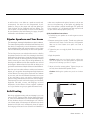
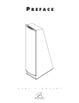
TM
M O N TA G E
u s e r ’ s
m a n u a l
MA R T I N LOGA N ®
the loudspeaker technology company
TM
CONTENTS
Contents . . . . . . . . . . . . . . . . . . . . . . . . . . . . . . .2
Installation in Brief . . . . . . . . . . . . . . . . . . . . . . . .3
Lifting Directions
Introduction . . . . . . . . . . . . . . . . . . . . . . . . . . . . .4
Operation . . . . . . . . . . . . . . . . . . . . . . . . . . . . . . .5
Signal Connection
Break-In
Placement . . . . . . . . . . . . . . . . . . . . . . . . . . . . . . .6
Listening Position
The Wall Behind the Listener
The Wall Behind the Speakers
The Side Walls
Experimentation
Final Placement . . . . . . . . . . . . . . . . . . . . . . . . . . . .7
The Extra “Tweak”
Enjoy Yourself
2
Contents
Room Acoustics . . . . . . . . . . . . . . . . . . . . . . . . . . .8
Your Room
Terminology
Rules of Thumb
Dipolar Speakers and Your Room . . . . . . . . . . . . . . .9
Solid Footing
Home Theater . . . . . . . . . . . . . . . . . . . . . . . . . .10
ATF (Advanced Thin Film) . . . . . . . . . . . . . . . . . .11
Frequently Asked Questions and Troubleshooting .12
General Information . . . . . . . . . . . . . . . . . . . . . .13
Specifications
Serial Number
Warranty and Registration
Service
Glossary of Audio Terms . . . . . . . . . . . . . . . . . . .14
INSTALLATION
IN
BRIEF
We know you are eager to hear your new Montage loudspeaker, so this section is provided to allow fast and easy
set up. Once you have it operational, please take the time to
read, in depth, the rest of the information in this manual. It
will give you perspective on how to attain the greatest possible performance from this most exacting transducer.
Step 1: Unpacking
Remove your new Montage speaker from the packing.
If you should experience any difficulties in the setup or
operation of your Montage speaker, please refer to the
Operation or Placement sections of this manual.
Step 3: Signal Connection
Use the best speaker cables you can. Higher quality cables,
available from your specialty dealer, are recommended
and will give you superior performance. Spade connectors
are suggested for optimum contact and ease of installation.
Should you encounter a persistent problem that cannot be
resolved, please contact your authorized MartinLogan dealer.
They will provide you with the appropriate technical analysis
to alleviate the situation.
WARNING!
•Refer servicing to a qualified technician.
•To prevent fire or shock hazard, do not
expose this module to moisture.
•Turn amplifier off should any abnormal
conditions occur.
•Do not drive speaker beyond its rated power.
Step 2: Placement
Place the Montage near the desired location. Please see
the ‘Placement’ section (page 6–7) for more details.
Attach your speaker cables to the signal input section on
the rear panel. Be consistent when connecting speaker leads
to the terminals on the back of the Montage. Take great
care to assign the same color to the (+) terminal on both
the speaker and the amplifier. Please see the ‘Operation’
section (page 5) for more details.
Step 4: Listen and Enjoy
Now, you may turn on your system and enjoy!
Lifting Directions
The lightning bolt flash with arrowhead symbol within
an equilateral triangle is intended to alert the user to
the presence of uninsulated “dangerous voltage” within
the product’s enclosure that may be of sufficient magnitude to constitute a risk of electric shock.
The exclamation point within an equilateral triangle is
intended to alert the user to the presence of important
operating and maintenance (servicing) instructions in
the literature accompanying the appliance.
This product complies with all applicable European directives.
Applicable directives:
EMC directive 89/336/EEC
1 The product will not cause electromagnetic interference.
2 The product is not adversely affected by electromagnetic
interference.
Figure 1. Montage lifting directions.
Installation in Brief
3
INTRODUCTION
Congratulations! You have invested in a new world of
high-performance audio!
The MartinLogan Montage represents the extension of an
intensive, dedicated group research program directed toward
establishing a world class reference monitor utilizing leadingedge technology, without compromising durability, reliability,
craftsmanship or aesthetic design.
The result of cumulative technology gleaned from previous
research and development projects, the Montage represents
the latest developments in advanced thin film and hybrid
loudspeaker technology.
4
Introduction
The materials in your new Montage speaker are of the
highest quality and will provide years of enduring enjoyment and deepening respect. Montage's state-of-the-art
Vojtko™ crossover is designed and manufactured with the
same meticulous attention, care and precision as those
found in MartinLogan's ultimate loudspeaker products.
This User’s Manual will explain in detail the operation of
your Montage speaker and the philosophy applied to their
design. A clear understanding of your speakers will insure
that you obtain maximum performance and pleasure from
this most exacting transducer. It has been designed and constructed to give you years of trouble-free listening enjoyment.
OPERATION
Signal Connection
Use the best speaker cables you can. The length and type
of speaker cable used in your system will have an audible
effect. Under no circumstance should a wire of gauge
higher (thinner) than #16 be used. In general, the longer
the length used, the greater the necessity of a lower gauge,
and the lower the gauge, the better the sound, with diminishing returns setting in around #8 to #12.
A variety of speaker cables are now available whose
manufacturers claim better performance than standard heavy
gauge wire. We have verified this in many cases, and the
improvements available are often more noticeable than the differences between wires of different gauge. The effects of cables
may be masked if the equipment is not of the highest quality.
We also recommend, if possible, that short runs of speaker
cable connect the power amplifier and speaker and that high
quality long interconnect cables be used to connect the
preamplifier and power amplifier. This results in the
power amplifiers being close to the speakers, which may
be practically or cosmetically difficult, but if the length of
the speaker cables can be reduced to a few meters, sonic
advantages may be obtained.
Connections are done at the signal input section on the rear
electronics panel of the Montage (see figure 2). Use spade
connectors for optimum contact. Make certain that all of
your connections are tight.
Be consistent when connecting speaker leads to the terminals on
the back of the Montage. Take great care to assign the same
color to the (+) terminal on both the speaker and the amplifier.
Figure 2. Single wire connection. One channel shown.
WARNING! Turn your amplifier off before making or breaking any signal connections!
Break-In
When you first begin to play your Montage speaker, it will
sound a bit bass shy. This is due to the high-quality, long-life
components used in our woofer. Montage’s woofer requires
at least 30 hours of break-in at 90 dB (moderate listening
levels) before any critical listening. The break-in requirements of the crossover components (and, to a lesser
degree, the ATF transducer) are equal.
Operation
5
PLACEMENT
Listening Position
By now your speakers should be placed approximately two to
three feet from the front wall (the wall in front of the listening
position), and at least one to two feet from the side walls. Your
sitting distance should be farther than the distance between
the speakers themselves. What you are trying to attain is
the impression of good center imaging and stage width.
sheet rock or textured wall is generally an adequate
surface if the rest of the room is not too bright and hard.
Sometimes walls can be too soft. If the entire front wall
consists of only heavy drapery, your system can sound too soft
or dull. You may hear dull, muted music with little ambience. Harder room surfaces will actually help in this case.
There is no exact distance between speakers and listener,
but there is a relationship. In long rooms, naturally, that
relationship changes. The distance between the speakers
will be far less than the distance from you to the speaker
system. However, in a wide room, you will still find that if
the distance from the listener to the speakers becomes
smaller than the distance between the speakers themselves, the image will no longer focus in the center.
The front surface should, optimally, be one long wall
without any doors or openings. If you have openings, the
reflection and bass characteristics from one channel to the
other can be different.
Now that you have positioned your speaker system, spend
some time listening. Wait to make any major changes in
your initial setup for the next few days as the speaker system itself will change subtly in its sound. Over the first 40
hours of play the actual tonal quality will change slightly
with deeper bass and more spacious highs resulting.
After a few days of listening you can begin to make refinements and hear the differences of those refinements.
The Wall Behind the Listener
Near-field reflections can occur from your back wall, the
wall behind the listening position. If your listening position
is close to the back wall, these reflections can cause problems and confuse the quality of imaging. Actually it is
better for the wall behind you to be soft than to be bright.
If you have a hard back wall and your listening position is
close to it, experiment with devices that will soften and
absorb information (i.e., wall hangings and possibly even
sound absorbing panels).
The Wall Behind the Speakers
The front surface, the wall behind your speakers, should not
be extremely hard or soft. For instance, a pane of glass
will cause reflections, brightness and confused imaging.
Curtains, drapery and objects such as bookshelves can be
placed along the wall to soften a hard surface. A standard
6
Placement
The Side Walls
The same requirements exist for side walls. Additionally, a
good rule of thumb is to have the side walls as far away
from the speaker sides as possible, minimizing near-field
side wall reflections. Sometimes, if the system is bright or
the imaging is not to your liking, and the side walls are
very near, try putting curtains or softening material directly
to the edge of each speaker. An ideal side wall, however,
is no side wall at all.
Experimentation
Toe-in
Now you can begin to experiment. First begin by toeing your
speakers in towards the listening area and then facing them
straight into the room. You will notice that the tonal balance
changes slightly. You will also notice the imaging changing.
Imaging
In their final location, the Montage’s should have a stage
width somewhat wider than the speakers themselves. On
well-recorded music, the instruments should extend
beyond the edges of each speaker to the left and to the
right, yet a vocalist should appear directly in the middle.
The size of the instruments should be neither too large nor
too small. Additionally, you should find good clues as to
stage depth. Make sure the vertical alignment, distance
from the front wall, and toe-in, is exactly the same from one
speaker to the other. This will greatly enhance the quality of
your imaging.
Bass Response
Your bass response should neither be one note nor too
heavy. It should extend to even the deepest organ passages, yet it should be tight and well defined. Kick-drums
should be tight and percussive—string bass notes should
be uniform and consistent throughout the entirety of the
run without any booming or thudding.
Tonal Balance
Voices should be natural and full, cymbals should be
detailed and articulate yet not bright and piercing, pianos
should have a nice transient characteristic and deep tonal
registers as well. If you cannot attain these virtues, read
the section on Room Acoustics (pages 8–9). This will give
you clues on how to get closer to those ideal virtues.
Final Placement
After obtaining good wall treatments and the proper
angle, begin to experiment with the distance from the wall
behind the speakers. Move your speaker slightly forward
into the room. What happened to the bass response?
What happened to the imaging? If the imaging is more
open and spacious and the bass response is tightened,
that is a superior position. Move the speakers back six
inches from the initial setup position and again listen to
the imaging and bass response. There will be a position
where you will have pinpoint imaging and good bass
response. That position is the point of the optimal placement from the front wall.
Now experiment with placing the speakers farther apart.
As the speakers are positioned farther apart, listen again,
not so much for bass response but for stage width and
good pinpoint focusing.
Your ideal listening position and speaker position
will be determined by:
•Tightness and extension of bass response
•Width of the stage
•Pinpoint focusing of imaging
Once you have determined the best of all three of these
considerations, you will have your best speaker location.
The Extra “Tweak”
A major cable company developed the following procedure
for speaker placement. As a final test of exact placement, use
these measurements for your speakers placement, and see
what can happen to the ultimate enhancement of your system’s
performance. These two basic formulas will determine optimum placement of your speakers to minimize standing waves.
1 Distance from the front wall (the wall in front of the listening position) to the center of the ATF transducer. To
determine distance from the front wall, measure the height
of your ceiling (inches) and multiply the figure by 0.618
(i.e., ceiling height in inches x 0.618 = the distance
from the front wall to the center of the ATF transducer).
2 Distance from the side-walls to the center of the ATF
transducer. To determine distance from the side walls,
measure the width of your room (inches) and divide by
18. Next, multiply the quotient by 5 (i.e., room width in
inches/18 x 5 = the distance from the side-walls to the
center of the ATF transducer).
Enjoy Yourself
The Montage is a very refined speaker and benefits from
care in setup. With these tips in mind you will find, over
your months of listening, that small changes can result in
measurable differences. As you live with your speakers, do
not be afraid to experiment with their positioning until you
find the optimal relationship between your room and
speaker system that gives to you the best results. Your
efforts will be rewarded.
You are now armed with the fundamental knowledge of
room acoustics and the specific fundamentals of the
Montage loudspeaker. Happy listening!
Placement
7
ROOM ACOUSTICS
Your Room
This is one of those areas that requires both a little background to understand and some time and experimentation
to obtain the best performance from your system.
Your room is actually a component and an important part of
your system. This component is a very large variable and can
dramatically add to, or subtract from, a great musical
experience.
All sound is composed of waves. Each note has its own wave
size, with the lower bass notes literally encompassing from
10 feet to as much as 40 feet. Your room participates in
this wave experience like a three-dimensional pool with
waves reflecting and becoming enhanced depending on
the size of the room and the types of surfaces in the room.
Remember, your audio system can literally generate all of
the information required to recreate a musical event in
time, space and tonal balance. The purpose of your
room, ideally, is to not contribute to that information.
However, every room does contribute to the sound, and
the better speaker manufacturers have designed their systems to accommodate this phenomenon.
Let’s talk about a few important terms before we begin.
Terminology
Standing Waves
The parallel walls in your room will reinforce certain notes to
the point that they will sound louder than the rest of the audio
spectrum and cause “one-note bass”, “boomy bass” or
“tubby bass”. For instance, 100Hz represents a 10 foot
wavelength. Your room will reinforce that specific frequency
if one of the dominant dimensions is 10 feet. Large objects
in the room such as cabinetry or furniture can help to minimize this potential problem. Some serious “audiophiles”
will literally build a special room with no parallel walls just
to help eliminate this phenomenon.
Reflective Surfaces (near-field reflections)
The hard surfaces of your room, particularly if close to your
speaker system, will reflect some waves back into the room
over and over again, confusing the clarity and imaging of
your system. The smaller sound waves are mostly affected
here, and occur in the mid and high frequencies. This is
where voice and frequencies as high as the cymbals occur.
8
Room Acoustics
Resonant Surfaces and Objects
All of the surfaces and objects in your room are subject to
the frequencies generated by your system. Much like an
instrument, they will vibrate and “carry on” in syncopation
with the music, and contribute in a negative way to the
music. Ringing, boominess, and even brightness can occur
simply because they are “singing along” with your music.
Resonant Cavities
Small alcoves or closet type areas in your room can be
chambers that create their own “standing waves” and can
drum their own “one-note” sounds.
Clap your hands. Can you hear an instant echo respond
back? You have near-field reflections. Stomp your foot on the
floor. Can you hear a “boom”? You have standing waves
or large panel resonances such as a poorly supported wall.
Put your head in a small cavity area and talk loudly. Can you
hear a booming? You’ve just experienced a cavity resonance.
Rules of Thumb
Hard vs. Soft Surfaces
If the front or back wall of your listening room is soft, it
might benefit you to have a hard or reflective wall in
opposition. The ceiling and floor should follow the same
basic guideline as well. However, the side walls should be
roughly the same in order to deliver a focused image.
This rule suggests that a little reflection is good. As a matter of fact, some rooms can be so “over damped” with
carpeting, drapes and sound absorbers that the music system can sound dull and lifeless. On the other hand,
rooms can be so hard that the system can sound like a
gymnasium with too much reflection and brightness. The
point is that balance is the optimum environment.
Breakup Objects
Objects with complex shapes, such as bookshelves, cabinetry and multiple-shaped walls can help break up those
sonic gremlins and diffuse any dominant frequencies.
Solid Coupling
Your loudspeaker system generates frequency vibrations or
waves into the room. This is how it creates sound. These
vibrations vary from 20 per second to 20,000 per second.
If your speaker system is not securely planted on the floor
or solid surface, it can shake as it produces sound and,
consequently, the sound can be compromised. If your
speaker is sitting on the carpet and only foot gliders are
used, the bass can be ill defined and even boomy. The
use of spikes is recommended to insure secured footing
for your speakers. (See Solid Footing, this page, for spike
information and installation instructions).
Dipolar Speakers and Your Room
The MartinLogan Montage loudspeakers are dipolar radiators.
This means that they produce sound from both their fronts and
their backs. Consequently, musical information is reflected
by the wall behind them and may arrive either in or out of step
with the information produced by the front of the speaker.
The low frequencies can either be enhanced or nulled by
the position from the front wall. Your Montage’s have been
designed to be placed two to three feet from the front wall
(the wall in front of the listening position) to obtain the best
results; however, your room may see things differently. So
listening to the difference of the bass response as a result of
the changes in distance from the front wall can allow you to
get the best combination of depth of bass and tonal balance.
Now that you know about reflective surfaces and resonant
objects, you can see how the midrange and high frequencies
can be affected. The timing of the initial wave as it radiates
to your ears, and then the reflected information as it arrives
at your ears later in time, can result in confusion of the
precious timing information that carries the clues to imaging.
Consequently the result is blurred imaging and excessive
brightness. Soft walls, curtains, wall hangings, or sound
dampeners can be effective if these negative conditions
occur (your dealer can give you good information here).
is best not to implement the spikes, however, until you are
secure in the positioning, as the spikes can damage the
floor if the speaker is moved. MartinLogan ETC spikes will
fit any common 1/4” x 20 thread insert that may be found
on your other audio equipment (racks, etc.)
Spike Installation Instructions:
1 Carefully lay your speaker on its side to gain access to
the bottom.
2 Remove existing feet or spikes. Thread new spikes into
holes and screw them in all of the way. If the speaker
does not sit level loosen one spike until level is
achieved.
3 Tighten the jam nut snugly by hand. Do not over tighten the nut.
4 Right the speaker.
Caution: Make sure your hands and any cabling are
clear of the spikes. Do not slide speaker as spikes are
sharp and can damage your floor or carpet.
5 Adjust to level by rotating spikes. Tighten the jam nut
securely when satisfied that speaker is level.
Caution: Walking the speaker may result in a broken
spike.
Solid Footing
After living and experimenting with your Montage’s, you may
want to use ETC (energy transfer coupler) Spikes (see figure
3), which are available from your local MartinLogan dealer
or from the Xtatic shop at www.martinlogan.com. With the
use of these spikes, the Montage will become more firmly
planted on the floor and, consequently, bass will tighten
and imaging will become more coherent and detailed. It
Figure 3. The ETC Spike.
Room Acoustics
9
HOME THEATER
It had long been the practice of stereo buffs to connect their
television to a stereo system. The advantage was the use
of the larger speakers and more powerful amplifier of the
stereo system. Even though the sound was greatly improved, it
was still mono and limited by the broadcast signal.
In the late 1970’s and early 1980’s two new home movie
formats became widely available to the public: VCR and
laser disc.
Surround Speakers
We recommend that the surround speakers play down
to 80 Hz or below. The surround speakers contain the
information that makes it appear that planes are flying over
your head. Some may suggest that this is the place to save
money and purchase a small, inexpensive speaker. If you
choose to do so, be prepared to upgrade in the future as
discrete six-channel digital encoding becomes available
and the demands on the surround speakers increase.
By 1985, both formats had developed into very high quality
audio/video sources. In fact, the sonic performance of some
video formats exceeded audio-only formats. Now, with
theater-quality sound available at home, the only element
missing was the "surround sound" presentation found in
movie houses.
Subwoofer
With any good surround system you will need a high-quality
subwoofer (the .1 in a 5.1 channel surround system). Most
movie soundtracks contain large amounts of bass information as part of the special effects. Good subwoofers
will provide a foundation for the rest of the system.
Fortunately, Dolby and DTS-encoded movies (which include
almost all movies) have the same surround sound information encoded on home releases as the theater films. All
that is required to retrieve this information is a decoder
and additional speakers and amps to reproduce it.
Home theater is a complex purchase and we recommend
that you consult your local MartinLogan dealer, as they
are well versed in this subject.
Each piece of a surround system can be purchased separately. Take your time and buy quality. No one has ever
complained that the movie was too real. The following list
and descriptions will give you only a brief outline of the
responsibilities and demands placed on each speaker.
Front Left and Front Right
If these speakers will be the same two used for your stereo
playback, they should be of very high quality and able to
play loudly (over 102 dB) and reproduce bass below 80 Hz.
Center Channel
This is the most important speaker in a video system, as
almost all of the dialogue and a large portion of the front
speaker information is reproduced by the center channel.
It is important that the center speaker be designed by
the same manufacturer as the front speakers, and that it is
recommended for use as a center speaker. This is not the
place to cut corners.
10
Home Theater
Figure 4. Montage loudspeakers as front and surround (effects) channels.
Fresco loudspeakers as center (effects) channel. Grotto subwoofers as 0.1
(effects) channel.
ATF (ADVANCED THIN FILM)
ATF Operation
The MartinLogan ATF transducer consists of a micro-thin,
low-mass Kaladex diaphragm with an ultra-light, etched
conductive aluminum surface suspended between two high
field strength neodymium super magnet arrays (see figure 5).
When an electrical current (music signal) passes through the
etched aluminum on the diaphragm's surface it is simultaneously pulled towards one of the neodymium arrays and
pushed away from the opposing array. When the direction of
current is reversed the diaphragm is simultaneously pushed
and pulled in the opposite direction, thus producing sound.
High Field Strength
—Superb Control and Efficiency
With a field strength almost 2000% more powerful than
traditional systems, Neodymium iron boron (NIB) rareearth super magnets are one of the world's strongest
commercially available magnetic materials. This incredible
field strength proves ideal for maintaining perfect control
over the low-mass Kaladex diaphragm. Super-low distortion
levels, high-resolution, and crystal-clear transparency are
just a few of the benefits resulting from this superb combination of low-mass diaphragm and high field strength.
Extremely Low-Mass Diaphragm
—Blazing Speed and Inner Detail
Low-mass diaphragms are crucial to a loudspeakers ability
to accurately reproduce sound. As the mass of a transducer's
diaphragm decreases, its ability to resolve detail increases.
With extremely low-mass characteristics, the ATF transducer
tracks the audio signal with almost perfect accuracy.
Push-Pull Operation = Ideal Linearity
Linearity is another factor contributing to a loudspeaker's
ability to achieve ultimate clarity, detail and resolution. By
positioning neodymium magnet arrays in a push-pull configuration, MartinLogan ATF transducer technology maintains
uniform diaphragm control, regardless of position as it
traverses the entire audio signal. The push-pull concept is
a major contributor to the linearity and sonic superiority of
ATF transducers.
MartinLogan ATF diaphragms are constructed of extremely
low mass Dupont Kaladex® PEN (polyethylene naphthalate)
—a material chemically similar to the low-mass PET (polyethelene terathylate) film used in MartinLogan's generation
2 electrostatic transducers, yet capable of handling the
high thermal requirements required for stable magnetic
thin film operation.
Direct Full-Surface Drive
Provides Outstanding Clarity
Unlike traditional voice coil driven systems, ATF diaphragms
are directly and uniformly driven throughout their entire
surface. This full-surface drive system results in ultra-fast
transient response with no cone break up and the ability
to accurately reproduce sound with great delicacy, nuance
and clarity.
Dipole Design For A Realistic, Open Sound Stage
The audio industry has long recognized that late arrival
reflective information significantly enhances the ambient
nature of sound reproduction. This ambient reflective
information dramatically contributes to a realistic, "you are
there" listening experience. MartinLogan's dipole radiation
pattern (radiating out of phase information from both the
front and back) ideally interacts with your listening environment to create this realistic sound stage. We have
contoured Montage's radiation pattern to emulate the same
dipole characteristics as our world standard setting electrostatic technology, resulting in the same outstanding
sound staging and 3-dimensionality.
Figure 5. Cut away view of an ATF transducer. Note the simplicity due
to minimal parts usage.
ATF (Advanced Thin Film)
11
FREQUENTLY ASKED QUESTIONS
AND
TROUBLESHOOTING
Frequently Asked Questions
Troubleshooting
How do I clean my speakers?
Just use a dust free cloth or a soft brush to remove the dust
from your speakers. We recommend a specialty cloth
(available at the Xtatic shop at www.martinlogan.com)
that cleans your speakers better than anything else we
have tried. Do not spray any kind of cleaning agent
on or in close proximity to the ATF element.
Output
• Check that all your system components are turned on.
• Check your speaker wires and connections.
• Check all interconnecting cables.
What size amplifier should I use?
We recommend an amplifier with 100 to 150 watts per
channel for most applications. Probably less would be
adequate for our smaller hybrids or when used in home
theater where a subwoofer is employed. Our hybrid
designs will perform well with either a tube or transistorized amplifier, and will reveal the sonic character of
either type. However, it is important that the amplifier be
stable operating into varying impedance loads: a stable
amplifier will be able to deliver twice its rated wattage
into 4 Ohms and should again double into 2 Ohms.
Could you suggest a list of suitable electronics and
cables that would be ideal for MartinLogan speakers?
The area of electronics and cable choice is probably
the most common type of question that we receive. It is
also the most subjective. We have repeatedly found that
brands that work well in one setup will drive someone
else nuts in another. We use many brands with great
success. Again, we have no favorites; we use electronics
and cables quite interchangeably. We would suggest
listening to a number of brands—and above all else—
trust your ears. Dealers are always the best source for
information when purchasing additional audio equipment.
Is there likely to be any interaction between my speakers and the television in my Audio/Video system?
We recommend that you keep your speakers at least one
foot away from the TV because of the dynamic woofer
they employ.
Will exposure to sunlight affect the life or performance of my speakers?
We recommend that you not place any loudspeaker in
direct sunlight. The ultraviolet (UV) rays from the sun can
cause deterioration of grill cloth, speaker cones, etc. Small
exposures to UV will not cause a problem. In general,
the filtering of UV rays through glass will greatly reduce the
negative effects.
12
Frequently Asked Questions and Troubleshooting
GENERAL INFORMATION
Specifications
Warranty and Registration
System Frequency Response
47–20,000 Hz ± 3 dB
Your Montage speaker is provided with an automatic Limited
90 Day Warranty coverage.
Sensitivity
90 dB/2.83 volts/meter
You have the option, at no additional charge, to receive a
Limited 5 Year Warranty coverage. To obtain the Limited
5 Year Warranty coverage you need to complete and return
the Certificate of Registration, included with your speakers,
and provide a copy of your dealer receipt, to MartinLogan
within 30 days of purchase.
Impedance
5 ohms
Crossover Frequency
2500 Hz
For your convenience MartinLogan also offers online warranty
registration at www.martinlogan.com.
Components
Air core coils, metal film and low dissipation electrolytic
capacitors
MartinLogan may not honor warranty service claims unless
we have a completed Warranty Registration on file!
Woofer/Mid-Range Drivers
2 x 6.5” (16.5cm) high rigidity aluminum cones with
extended throw drive assembly, non-resonance asymmetrical chamber format; bass reflex
If you did not receive a Certificate of Registration with your
new Montage speaker, you cannot be assured of having
received new units. If this is the case, please contact your
authorized MartinLogan dealer.
High Frequency Driver
1.5" x 2.25" (3.8cm x 5.7cm) ATF Transducer
Power Handling
150 watts rms
Weight
30 lbs. each (13.6 kg)
Size
9.44” W × 11.69” D × 38” H
(24cm W × 29.7cm D × 96.5cm H)
Serial Number
The serial numbers for your new Montage loudspeakers are
located on the bottom of the speakers.
Service
Should you be using your MartinLogan product in a country
other than the one in which it was originally purchased,
we ask that you note the following:
1 The appointed MartinLogan distributor for any given
country is responsible for warranty servicing only on
units distributed by or through it in that country in
accordance with its applicable warranty.
2 Should a MartinLogan product require servicing in a
country other than the one in which it was originally
purchased, the end user may seek to have repairs performed by the nearest MartinLogan distributor, subject
to that distributor’s local servicing policies, but all cost
of repairs (parts, labor, transportation) must be born by
the owner of the MartinLogan product.
3 If, after owning your speakers for six months,
you relocate to a country other than the one in
which you purchased your speakers, your warranty
may be transferable. Contact MartinLogan for details.
General Information
13
GLOSSARY
OF
AUDIO TERMS
AC. Abbreviation for alternating current.
DC. Abbreviation for direct current.
Active crossover. Uses active devices (transistors, ICs, tubes)
and some form of power supply to operate.
Diffraction. The breaking up of a sound wave caused by
some type of mechanical interference such as a cabinet edge,
grill frame or other similar object.
Amplitude. The extreme range of a signal. Usually measured from the average to the extreme.
Diaphragm. A thin flexible membrane or cone that vibrates
in response to electrical signals to produce sound waves.
Arc. The visible sparks generated by an electrical discharge.
ATF. The abbreviation for advanced thin film.
Bass. The lowest frequencies of sound.
Bi-Amplification. Uses an electronic crossover, or line-level
passive crossover, and separate power amplifiers for the
high and low frequency loudspeaker drivers.
Capacitance. That property of a capacitor which determines
how much charge can be stored in it for a given potential
difference between its terminals, measured in farads, by
the ratio of the charge stored to the potential difference.
Distortion. Usually referred to in terms of total harmonic
distortion (THD) which is the percentage of unwanted harmonics of the drive signal present with the wanted signal.
Generally used to mean any unwanted change introduced
by the device under question.
Driver. See transducer.
Dynamic Range. The range between the quietest and the
loudest sounds a device can handle (often quoted in dB).
Efficiency. The acoustic power delivered for a given electrical
input. Often expressed as decibels/watt/meter (dB/w/m).
Capacitor. A device consisting of two or more conducting
plates separated from one another by an insulating material
and used for storing an electrical charge. Sometimes called
a condenser.
ESL. The abbreviation for electrostatic loudspeaker.
Clipping. Distortion of a signal by its being chopped off. An
overload problem caused by pushing an amplifier beyond
its capabilities. The flat-topped signal has high levels of
harmonic distortion which creates heat in a loudspeaker
and is the major cause of loudspeaker component failure.
Hybrid. A product created by the marriage of two different
technologies. Meant here as the combination of a dynamic woofer with an electrostatic or ATF transducer.
Headroom. The difference, in decibels, between the peak
and RMS levels in program material.
Hz (Hertz). Unit of frequency equivalent to the number of
cycles per second.
CLS. The abbreviation for curvilinear linesource.
Crossover. An electrical circuit that divides a full bandwidth
signal into the desired frequency bands for the loudspeaker
components.
dB (decibel). A numerical expression of the relative loudness
of a sound. The difference in decibels between two sounds is
ten times the Base 10 logarithm of the ratio of their power levels.
14
Glossary of Audio Terms
Imaging. To make a representation or imitation of the original
sonic event.
Impedance. The total opposition offered by an electric circuit
to the flow of an alternating current of a single frequency. It
is a combination of resistance and reactance and is measured
in ohms. Remember that a speaker’s impedance changes
with frequency, it is not a constant value.
Inductance. The property of an electrical circuit by which
a varying current in it produces a varying magnetic field
that introduces voltages in the same circuit or in a nearby
circuit. It is measured in henrys.
Inductor. A device designed primarily to introduce inductance
into an electrical circuit. Sometimes called a choke or coil.
Linearity. The extent to which any signal handling process
is accomplished without amplitude distortion.
Midrange. The middle frequencies where the ear is the most
sensitive.
NAC. The abbreviation for natural ambience compensation.
Passive crossover. Uses no active components (transistors, ICs, tubes) and needs no power supply (AC, DC,
battery) to operate. The crossover in a typical loudspeaker
is of the passive variety. Passive crossovers consist of
capacitors, inductors and resistors.
Phase. The amount by which one sine wave leads or lags
a second wave of the same frequency. The difference is
described by the term phase angle. Sine waves in phase
reinforce each other; those out of phase cancel.
Resistor. A device used in a circuit to provide resistance.
Resonance. The effect produced when the natural vibration frequency of a body is greatly amplified by reinforcing
vibrations at the same or nearly the same frequency from
another body.
Sensitivity. The volume of sound delivered for a given
electrical input.
Stator. The fixed part forming the reference for the moving
diaphragm in a planar speaker.
THD. The abbreviation for total harmonic distortion. (See
Distortion)
TIM. The abbreviation for transient intermodulation distortion.
Transducer. Any of various devices that transmit energy
from one system to another, sometimes one that converts
the energy in form. Loudspeaker transducers convert electrical energy into mechanical motion.
Transient. Applies to that which lasts or stays but a short
time. A change from one steady-state condition to another.
Pink noise. A random noise used in measurements, as it
has the same amount of energy in each octave.
Tweeter. A small drive unit designed to reproduce only
high frequencies.
Polarity. The condition of being positive or negative with
respect to some reference point or object.
Wavelength. The distance measured in the direction of
progression of a wave, from any given point characterized
by the same phase.
RMS. Abbreviation for root mean square. The effective value
of a given waveform is its RMS value. Acoustic power is
proportional to the square of the RMS sound pressure.
White noise. A random noise used in measurements, as it
has the same amount of energy at each frequency.
Resistance. That property of a conductor by which it opposes
the flow of electric current, resulting in the generation of
heat in the conducting material, usually expressed in ohms.
Woofer. A drive unit operating in the bass frequencies only.
Drive units in two-way systems are not true woofers but
are more accurately described as being mid/bass drivers.
Glossary of Audio Terms
15
MA R T I N LOGA N ®
the loudspeaker technology company
2101 Delaware Street, Lawrence, Kansas 66046, USA
tel 785.749.0133
fax 785.749.5320
©2003 MartinLogan. All rights reserved.
www.martinlogan.com
Rev. #092903