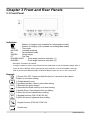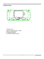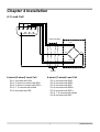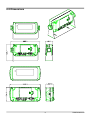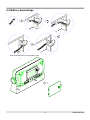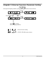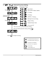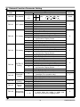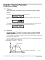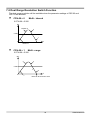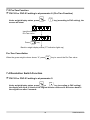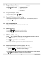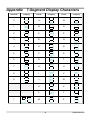
1
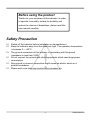
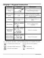
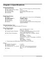
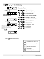
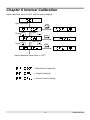
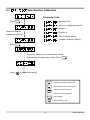
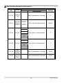
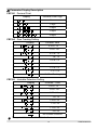
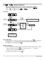
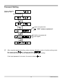
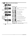
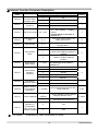
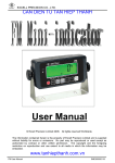
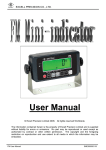
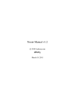
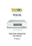
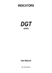
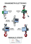
Mini-indicator User Manual Table of Contents Safety Precaution ............................................................................................................ 2 Chapter 1 Keypad Instruction ........................................................................................ 3 Chapter 2 Specifications................................................................................................. 4 Chapter 3 Front and Rear Panels................................................................................... 5 3-1 Front Panel .......................................................................................................... 5 3-2 Rear Panel ........................................................................................................... 6 Chapter 4 Installation ...................................................................................................... 7 4-1 Load Cell.............................................................................................................. 7 4-2 Dimensions ......................................................................................................... 8 4-3 Battery Assemblage ............................................................................................. 9 Chapter 5 External Function Parameter Setting......................................................... 10 5-1 External Function Setting............................................... 11 5-2 RS-232 Setting................................................................. 13 Chapter 6 Internal Calibration ...................................................................................... 18 Specification Calibration ................................................ 19 6-1 Weight Calibration ........................................................... 22 6-2 Internal Function Setting................................................. 24 6-3 6-4 Error Messages................................................................................................. 26 Chapter 7 Special Function .......................................................................................... 27 7-1 Animal Scale Setting ........................................................................................ 27 7-2 Dual Range Resolution Switch Function ....................................................... 28 7-3 Pre-Tare Function ............................................................................................. 29 7-4 Resolution Switch Function ............................................................................ 29 7-5 Maintain Beeper Value Setting ........................................................................ 30 Chapter 8 Interface ........................................................................................................ 31 8-1 OP-01 RS-232 / RS-485 Serial Output with RTC............................................. 31 Chapter 9 Maintenance ................................................................................................. 33 9-1 Restore Default Setting for All Parameters(General Certification) .............. 33 9-2 Restore Default Setting for All Parameters (OIML Certification) ................. 33 9-3 Restore Default Setting for General Function Parameters........................... 33 9-4 Self-test Mode ................................................................................................... 33 9-4-1 Program Version Number.................................................................... 35 9-4-2 7-segment Display Testing.................................................................. 35 9-4-3 Keypad & Calibration Switch Testing.................................................35 9-4-4 A/D Conversion Value.......................................................................... 35 9-4-5 EEPROM Testing .................................................................................. 35 9-4-6 RTC Time & Date Testing..................................................................... 35 9-4-7 RS-232 Serial Output Interface Testing ( OP - 01 ) ............................ 35 Appendix 7-Segment Display Characters ................................................................ 36 1 ZSME300000148 Before using the product Thanks for your purchase of this indicator. In order to operate it smoothly, extend its durability and reduce the chance of breakdown, please read this user manual carefully. Safety Precaution Switch off the indicator before installation or dismantlement. Keep the indicator away from the direct sun light. The operation temperature is between 0 ~ +40°C. The ground connection of this indicator is necessary and this ground impedance is less than 100Ω. Do not connect the ground with other equipments which need huge power consumption. Non-ground or incorrect connection might cause an electric shock or a product breakdown. Please wait more than one minute before re-power on. 2 ZSME300000148 Chapter 1 Keypad Instruction Function Operation Press and hold ENTER Description , General Function Setting Refer to <Chapter 5> External Function Parameter Setting for details then press Weighing Parameter Adjust calibration switch Setting to ON Calibration Self-test Mode Restore Default Setting for All Parameters Setting for decimal point, capacity, division, zero tracking, and unstable detection, etc. Refer to 6-1 Specification Setting for details. Adjust calibration switch to ON Refer to 6-2 Weight Calibration for details. During the countdown of power on, press and hold ZERO Refer to 9-4 Self-test Mode for details. Adjust calibration switch to ON, and then press and Refer to 9-1 for details. ENTER hold During the countdown of power on, press and Restore Default Setting for General Function Parameters hold Refer to 9-3 for details. ENTER . During the operation, use the following keys to complete all works. ZERO ⇒ Increase the flash value by one ZERO ⇒ Decrease the flash value by one GROSS NET ⇒ Move the cursor leftward F2 ENTER ESC 3 ⇒ Move the cursor rightward ⇒ Save setting ⇒ Abort setting / Exit ZSME300000148 Chapter 2 Specifications Analog Specification Load Cell Current Max. Load Cell Input Voltage Input Sensitivity Conversion Rate Resolution : DC 5 V ±5% 60 mA (Up to Four 350 Ω Load Cells) : 16 mV : 0.15 μV/d or more : Approximately 120 times/s (max.) : 20 bits Digital Specification Display Display Frequency Display Range Min. Division Decimal Point Memory : LCD, 6 digits, 25.4 x 10 mm (W x H), LED backlight : 50 times/s (max) : - 999999 ~ 999999 : 1, 2, 5, 10, 20, 50 : 0, 0.0, 0.00, 0.000, 0.0000 : Calibration parameters and function settings are all stored in EEPROM. Optional Interface Card OP-01 RS-232 / RS-485 (Includes RTC Function) Power Requirement Adaptor Spec : Input 120 / 230 V AC 50 ~ 60 Hz Output 9 V / 1000 mA Optional 2 types of batteries : 6 V NiMH rechargeable battery kit (5 pcs) (1800 mA/hr) or general batteries (5 pcs) Max. Power Consumption :110 mA (with 4 Load Cells + backlight + RS-232 interface) NiMH battery → 15 hours General battery → 24 hours 45 mA (with 1 Load Cell + no backlight + no RS-232 interface) NiMH battery → 36 hours General battery → 60 hours Please charge the Ni-MH battery at least 12~14 hours for first use. Others Operation Temperature : 0 ~ 40 °C Operation Humidity : < 85% R.H. Dimensions (W × D × H) (mm) : 193 × 49.5 × 94.4 (excluding protrusions) 225 × 60 × 134.7 (including protrusions) Weight : 700 g 4 ZSME300000148 Chapter 3 Front and Rear Panels 3-1 Front Panel Indication: : Battery is charged (only available for rechargeable model) : Battery is charging (only available for rechargeable model) TARE : Tare mode MOTION : Unstable weighing M+ : Accumulation mode GROSS : Gross weight PT : Pre-Tare RANGE1/HOLD : Dual-range resolution indication (1) : Dual-range resolution indication (2) RANGE2 Description of RANGE1 and HOLD: The light is default on. When using CFN-05 Animal Scale Mode or FNC-07 Maintain Beeper Value, it works as HOLD LED light. When opening dual-range resolution, it works as RANGE1 LED light. CFN-05 Animal Scale Mode and FNC-07 Maintain Beeper Value can’t be run at the same time. Keypad: ESC 1) Power ON / OFF. Press and hold this key for 3 seconds to shut down. 2) Abort or exit when setting. ZERO 1) Weight backs to zero. 2) Increase the flash value by one when setting. TARE 1) Eliminate the gross weight. 2) Decrease the flash value by one when setting. G R O SS N ET F2 1) Switch Gross / Net weight shown on display. 2) Move the cursor leftward when setting. 1) Keypad function (FNC-02 & FNC-03). 2) Move the cursor rightward when setting. Keypad function (FNC-02 & FNC-03). ENTER Confirm key. 5 ZSME300000148 3-2 Rear Panel 1 2 3 5 4 1. Battery Case 2. RS-232 / RS-485 Input / Output 3. DC 9 V Power Input 4. Calibration Switch 5. Load Cell Connect Socket 6 ZSME300000148 Chapter 4 Installation 4-1 Load Cell 4 5 9 2 3 8 7 1 6 Load cell cable Load cell EXC+ SEN+ SIG+ SIG- EXCSEN- Shield 4-wired (5-wired) Load Cell 6-wired (7-wired) Load Cell Pin 1 connects with SIG+ Pin 2, 3 short to connect with EXCPin 4, 5 short to connect with EXC+ Pin 6, 7, 8 connect with shield Pin 9 connects with SIG- Pin 1 connects with SIG+ Pin 2 connects with SENPin 3 connects with EXCPin 4 connects with SEN+ Pin 5 connects with EXC+ Pin 6, 7, 8 connect with shield Pin 9 connects with SIG- 7 ZSME300000148 4-2 Dimensions 8 ZSME300000148 4-3 Battery Assemblage Stuff the surplus wires into the battery case. 將多餘的電線塞入電池孔中 9 ZSME300000148 Chapter 5 External Function Parameter Setting ENTER Under general weighing condition, press , and the screen will show: ENTER Press ZERO Press TA R E key key ENTER ESC Press to escape. Back to weighing condition. ⇒ External function setting ⇒ RS-232 / RS-485 interface function 10 ZSME300000148 5-1 External Function Setting Parameter Code ⇒ Key Disable Press ENTER ⇒ DSP Update (Display Update) ⇒ F1 Setting ⇒ F2 Setting Select the desired parameter code. ⇒ ENTER + F2 Setting ⇒ Backlight Function Setting Press ENTER ⇒ Beeper Setting ⇒ Maintain Beeper Value ⇒ Auto-power Off The screen shows previous parameter setting. Enter the desired parameter setting. Press Press ESC ENTER . to escape the setting. ZERO TA R E ⇒ Decrease the flash value by one GROSS NET ⇒ Move the cursor leftward F2 ENTER ESC 11 ⇒ Increase the flash value by one ⇒ Move the cursor rightward ⇒ Save setting ⇒ Abort setting or exit ZSME300000148 External Function Parameter Setting Parameter Code Function FNC-00 Key disable FNC-01 DSP Update FNC-02 F1 Setting Parameter 0000 ↓ 1111 0 1 2 3 4 0 1 2 3 4 FNC-03 F2 Setting 5 6 0 1 2 3 4 FNC-04 ENTER+F2 Setting 5 6 0 1 2 3 4 5 6 FNC-05 FNC-06 FNC-07 FNC-08 Backlight Setting Beeper Setting Maintain Beeper Value Auto-power Off (Minutes) 0 1 2 0 1 0à 1 2 0 1 ~ 60 0 Setting Value Description ON 0000 is corresponding to:(from left to right) ZERO TARE 1 OFF GROSS NET F2 No Limit 20 times/s 10 times/s 5 times/s 1 times/s Print (printing) Units (units switch) M+ (accumulation and printing) MC (memory clearing) Weight / Times Accumulation / Weight Accumulation Display Switch HR (high resolution switch) Pre-Tare (Pre-Tare function) Print (printing) Units (units switch) M+ (accumulation and printing) MC (memory clearing) Weight / Times Accumulation / Weight Accumulation Display Switch HR (high resolution switch) Pre-Tare (Pre-Tare function) Print (printing) Units (units switch) M+ (accumulation and printing) MC (memory clearing) Weight / Times Accumulation / Weight Accumulation Display Switch HR (high resolution switch) Pre-Tare (Pre-Tare function) Auto Backlight On (backlight on in operation only) Backlight On (backlight always on) Backlight Off Beeper off Beeper on No function Mode 1 Mode 2 No function It works when the weight is stable and non-key is pressed in weighing mode. Default Setting 0Ã000 1 5 1 0 1 1 0 0 The symbol “Ô is standard for OIML Certification in context. 12 ZSME300000148 5-2 RS-232 Setting Parameter Code Press ⇒ Information Pattern ENTER ⇒ Transmission Method ⇒ Transmission Rate Select the desired parameter code with ⇒ Parity, Bit Length, Stop Bit ⇒ Unstable or Over Load ⇒ Auto Transmission Condition ⇒ Command Address Press ENTER ⇒ Output Format ⇒ Transmission Times The screen shows previous parameter setting. Enter the desired parameter setting. Press ENTER . Press ESC ⇒ Date Setting ⇒ Time Setting to escape the setting. ZERO TA R E ⇒ Decrease the flash value by one GROSS NET ⇒ Move the cursor leftward F2 ENTER ESC 13 ⇒ Increase the flash value by one ⇒ Move the cursor rightward ⇒ Save setting ⇒ Abort setting or exit ZSME300000148 OP-01/ RS-232 / RS-485 Interface Function Parameter Code Function RS1-00 Information Pattern RS1-01 Transmission Method RS1-02 Transmission Rate Parameter 0 1 2 3 4 5 6 7 0 1 2 3 4 0 1 2 3 0 RS1-03 Parity, Bit Length, Stop Bit 1 2 RS1-04 Unstable or Over Load RS1-05 Auto Transmission Condition RS1-06 Command Address RS1-07 Output Format 0 1 0 1 00 ↓ 99 0à 1 Setting Value Description Display Correspondingly Gross Weight Net Weight Tare Weight Accumulation Value Times Accumulation Value Output with Date & Time PT Output with Date & Time Continuous Transmission Auto Transmission F2 Press or for transmission Command Mode (no address) Command Mode (with address) 1 200 2 400 4 800 9 600 No Parity N,8,1 8 Bits Length 1 Stop Bit Odd Parity, O,7,1 7 Bits Length, 1 Stop Bit Even Parity, E,7,1 7 Bits Length, 1 Stop Bit Continuous Output Stop Output Positive (over + 10d) Positive / Negative (over + 10d, under – 10d) Default Setting 0 0 3 0 0 0 Available only if RS1-01 setting is “4” 0 Standard Format UMC 600 0 The symbol “Ô is standard for OIML Certification in context. 14 ZSME300000148 0 1 2 3 4 5 Transmission Times RS1-08 No Limit 1 times/s 2 times/s 5 times/s 10 times/s 20 times/s 4 Date Setting Time Setting RS1-09 RS1-10 Remark: This is general certification option when the parameter is set for “0~5” in RS1-00 and the data is transmitted to printer. This is general certification option when the parameter is set for “6” in RS1-00 and the parameter is set for “6” in FNC-02 (or the parameter is set for “6” in FNC-03). This is general certification option when the parameter is set for “0” in RS1-04 and the parameter is set for “6” in RS1-00. Transmission Format RS1-00 ⇒ 0 ~ 3 S T , Header 1 G S , + 1 Header 2 2 3 4 . 5 6 Weight Data (8 digits) g CR LF Unit Terminators Header 1 ST: Stable Weight / US: Unstable Weight / OL: Weight Overload Header 2 GS: Gross Weight / NT: Net Weight / TR: Tare Weight Data (8 digits) The first digit of weight data indicates “+ / - ” value of weight. The other 7 digits, including decimal point, indicate the weight value. If the weight is over load (Header 1: OL), the screen only shows “+ / - ” and decimal point. Unit (kg, t or “blank”)à or kg, lb, t or “blank” Terminators CR and LF are data termination code. RS1-00 = 4 T N , 1 2 3 CR LF The symbol “Ô is standard for OIML Certification in context. 15 ZSME300000148 RS1-00 = 5 T W , + 1 2 3 4 . 5 6 k g CR LF RS1-00 = 6 D A T E : 2 0 X X / X X / T I M E : X X : X X : X X CR LF G R O S : + 1 2 3 4 . 5 6 k g CR LF N E T : + 1 2 3 4 . 5 6 k g CR LF T A R : + 1 2 3 4 . 5 6 k g CR LF T N : X X X CR LF T W : + 1 2 3 4 . 5 6 k g CR LF X X CR LF S E X X CR LF RS1-00 = 7 D A T E : 2 0 X X / X X / T I M E : X X : X X : X X CR LF G R O S : + 1 2 3 4 . 5 6 k g CR LF N E T : + 1 2 3 4 . 5 6 k g CR LF T A R : + 1 2 3 4 . 5 6 k g CR LF P T + 1 2 3 4 . 5 6 K g CR LF T N : X X X CR LF T W : + 1 2 . 5 6 k g CR LF E S 3 16 4 ZSME300000148 Command Mode Command Function Command Function READ / RW Weight Reading CT Tare Clearing ZERO / MZ Weight Re-zeroing Rl Weight Accumulation Rm Times Accumulation TARE / MT Gross Weight Deducting NTGS Gross / Net Switch Rn Date MG Gross Weight Indicating Ro Time MN Net Weight Indicating AT DT Weight and Times Accumulation Weight and Times Accumulation Clearing n After setting above commands, it must add the termination code “CR (0DH) and LF (0AH)”. o If the command is not correct, it shows “E” + “Command Unidentified”. p If the command mode is chosen with address (RS1-01 = 4), add “@ address” in front of each command. Example: When RS1-06 = 1, for reading weight value, the whole complete command should be “@01RW (CR) (LF)”. 17 ZSME300000148 Chapter 6 Internal Calibration Adjust calibration switch to “ON”, and the screen displays: After 2 seconds ENTER Press ZERO Press TA R E ENTER Press ZERO Press TA R E ENTER Adjust calibration switch back to “OFF”. ⇒ Specification Calibration ⇒ Weight Calibration ⇒ Internal Function Setting 18 ZSME300000148 6-1 Specification Calibration Parameter Code Press ENTER ⇒ Decimal Point ⇒ Maximum Weighing Capacity ⇒ Division 1 Select the desired parameter code with ⇒ Division 2 ⇒ Zero Tracking Setting ⇒ Unstable Detection Setting Press ENTER The screen shows previous parameter setting. Enter the desired parameter setting. Press Press ESC ENTER . to escape the setting ZERO TA R E ⇒ Decrease the flash value by one GROSS NET ⇒ Move the cursor leftward F2 ENTER ESC 19 ⇒ Increase the flash value by one ⇒ Move the cursor rightward ⇒ Save setting ⇒ Abort setting or exit ZSME300000148 Specification Parameter Description Parameter Function Code Parameter CSP-00 Decimal Point CSP-01 Maximum Weighing Capacity 999999 ↓ 000000 Setting Value Description Default Setting Refer to descriptions in next page. 0 Max. value for weight display 999999 Min. value for weight display 1 Min. value for weight display 1 1 2 CSP-02 Division 1 5 10 20 50 1 2 CSP-03 Division 2 5 10 20 50 CSP-04 Zero Tracking Setting Refer to descriptions in next page. 0.25d CSP-05 Unstable Detectiion Setting Refer to descriptions in next page. 0.25d 20 ZSME300000148 Parameter Display Description CSP-00 Decimal Point Display Decimal Point Digit None CSP-04 . 1 digit . 2 digits . 3 digits . 4 digits Zero Tracking Setting Display Division/Time 0.25 d / 1 sà . 0.5 d / 1 sà . 0.75 d / 1 s . 1d / 1 s 1.25 d / 2 s . 1.5 d / 2 s . 1.75 d / 2 s . 2 d / 2s No Zero Tracking CSP-05 Unstable Detection Setting Display Division / Time 0.25 d / 1 sà . 0.5 d / 1 sà . 0.75 d / 1 s . 1d / 1 s 1.25 d / 2 s . 1.5 d / 2 s . 1.75 d / 2 s . 2d/2s No Unstable Detection The symbol “Ô is standard for OIML Certification in context. 21 ZSME300000148 6-2 Weight Calibration Turn on and warm up the machine for 15 to 30 minutes before calibration. Adjust the calibration switch to “ON”, and the screen will show Press TARE or ZERO . . to select Procedure ENTER ENTER Zero Calibration Zero calibration completed ESC Place weights and set the weight. ENTER Weight Calibration ESC ENTER Confirmed Set calibration switch to “OFF” Zero Calibration ENTER a) Ensure nothing on the platter. After the scale being stable, press , and the screen will display “……. ”. The zero calibration will be completed after 5 seconds. b) To abort zero calibration, just press ESC . Weight Calibration a) Place an object which weight is known on the platter. Input the weight value and wait the scale to be stable, then press ENTER . The screen will show “------”. The weight calibration will be completed after 5 seconds. b) To abort weight calibration, just press ESC 22 . ZSME300000148 Password Setting Adjust calibration switch to “ON” After 2 seconds ZERO Input new password “0000” means no password. ENTER Confirm new password (input again) ENTER After complete password setting, when entering calibration mode or function setting mode, the screen shows for 1 second, and then . It’s necessary to input the correct password to continue each setting. If the input password is incorrect, the screen shows 23 . ZSME300000148 6-3 Internal Function Setting Press ENTER Parameter Code ⇒ Tare or Zero Function under Unstable Status ⇒ Zero when Scale Turned on Select the desired parameter code with ⇒ Back to Zero Range ⇒ Filter Sampling Rate Press ENTER ⇒ Filter Strength ⇒ Animal Scale Mode The screen shows previous parameter setting. Enter the desired parameter setting. Press ENTER . ⇒ Animal Scale Stable Range ⇒ Animal Scale Sampling Frequency ⇒ Dual Range Resolution Setting ⇒ Midpoint Setting for Dual Range Resolution ⇒ Gravity Calibration Press ESC ⇒ Operation of Accumulative Value/ Times upon Unstable Condition to escape the setting 24 ZSME300000148 Internal Function Parameter Description Parameter Code Function CFN-00 Tare or Zero Function under Unstable Status CFN-01 Zero when Scale Turned on 0 1 ON à OFF 1 ON 0%: Full range re-zero 1% ~ 30%: Capacity × ± setting value% (The parameter is less than or equal to 2.) à 2 The larger number setting, the lower speed rate is. 6 0% ~ 30% CFN-03 Filter Sampling Rate 0~9 CFN-04 Filter Strength 0~5 The larger number setting, the stronger filter is. 0 OFF 0 Mode 1: The weight value won’t be shown if the weighing condition is unstable. Mode 2: The weight value shows in stable or unstable weighing condition. Mode 2: Stable Range Setting (The parameter is less than or equal to 10.) à 8 times 1 16 times 2 32 times 3 64 times 4 128 times 0 Multi - interval 1 Multi - range 0 ~ 999999 Set the demarcation point for dual range resolution. 1 2 CFN-06 CFN-07 Animal Scale Stable Range Animal Scale Sampling Frequency CFN-08 Dual Range Resolution Setting CFN-09 Midpoint Setting for Dual Range Resolution CFN-10 CFN-11 Gravity Calibration Operation of Accumulative Value/ Times upon Unstable Condition 1 OFF Back to zero range Animal Scale Mode Default Setting 0 CFN-02 CFN-05 Setting Value Description Parameter 0 ~ 100% 9.78032 | 9.83218 Gravity calibration for the different using & production zone. 1 Zero when Scale turned on. 0 ON 1 2 0 10 2 0 5 000 9.79423 1 1 à OFF The symbol “Ô is standard for OIML Certification in context. 25 ZSME300000148 6-4 Error Messages (1) Load Cell or A/D circuit is abnormal. (2) Real weighing value is lower than or equal to zero value. (3) Internal resolution is lower than 0.15 μV/d range. (4) . Incorrect password (5) Internal value is lower than zero range. (6) Internal value is higher than zero range. 26 ZSME300000148 Chapter 7 Special Function 7-1 Animal Scale Setting 2 CFN-05 = 1 (Animal Scale Mode1: The weight value won’t be shown if the weighing condition is unstable.) When there is nothing on the platter, the screen will show: When an object is on the platter, take a 20-gram object for example, the screen will show: . The weight value will be kept on the display if the weight is lower than 10d or you can push “Enter” key to reset weighing process, then the screen will show: 2 CFN-05 = 2 (Animal Scale Mode 2: The weight value shows in stable or unstable weighing condition The weight value shows on the display under the stable or unstable weighing condition.) When the weight value reaches the range of CFN-06 and CFN-07 setting, the screen will keep showing the weight value. When the weight value is over the range of CFN-06 and CFN-07 setting, the screen will show the normal weight measurement. For example: CFN-06=30 CFN-07=2 WT Weight Holding 30d Cancellation of Weight Holding 32 Times 10d T 27 ZSME300000148 7-2 Dual Range Resolution Switch Function The dual range resolution will be available when the parameter settings of CSP-02 and CSP-03 are different. 2 CFN-08 = 0 Multi - interval If CFN-09 = 5 000 WT Division 2 2 5 000 1 T 0 Division 1 2 CFN-08 = 1 Multi - range If CFN-09 = 5 000 WT 2 2 5 000 T 2 T 0 1 Recover when back to zero 28 ZSME300000148 7-3 Pre-Tare Function 2 FNC-02 or FNC-03 setting is at parameter 6. (Pre-Tare Function) Under weight display status, press screen will show: F2 or key (according to FNC setting), the Input the desired Pre-Tare value Press ENTER key Back to weight display status (PT indication lights up) Pre-Tare Cancellation When the gross weight column shows “0”, press TA R E key to cancel the Pre-Tare value. 7-4 Resolution Switch Function 2 FNC-02 or FNC-03 setting is at parameter 5. F2 Under weight display status, press or key (according to FNC setting), the display will show 10 times of the original division value and it will return back to the original one after 5 seconds. 29 ZSME300000148 7-5 Maintain Beeper Value Setting Mode 1 RS-232 transmission mode enters into HOLD value transmission mode automatically. When the weight is higher than 10d, the indicator holds the max value of weight. Press ENTER key to unlock HOLD mode. RS-232 tansmits one data of PEAK of HOLD value when press ENTER . Display Enter key Mode 2 RS-232 transmission mode enters into HOLD value transmission mode automatically. When the weight is higher than 10d, the indicator holds the max value of weight. When the weight is lower than 10d, the indicator unlocks HOLD value automatically and shows the weight value which is lower than 10d. RS-232 tansmits one data of PEAK HOLD value. The data point is from PEAK HOLD value to lower than 10d. Display 30 ZSME300000148 Chapter 8 Interface 8-1 OP-01 RS-232 / RS-485 Serial Output with RTC (Real Time Clock) CN2 CN3 CN2 CN3 123 123 123 123 Short 1 and 2 pins to get RS-485 output. Pin Allocation of Rear Panel 4 5 9 Short 2 and 3 pins to get RS-232 output. 8 1 2 3 7 6 Pin Function 2 RXD 3 TXD 5 SG 6 DA 7 DB RS-485 interface is capable to connect up to 10 mini-indicators. 31 ZSME300000148 Connection Description (RS-485) Terminal Resistant Host EX0419 # 1 RS - 06 = 01 EX0419 # 2 RS - 06 = 02 EX0419 # 10 RS - 06 = 10 Notice ♦ If the terminal resistant is built-in the host interface, it’s not necessary to connect with another one from outside. ♦ If the host computer is no signal ground (SG), it’s not necessary to connect with it. 32 ZSME300000148 Chapter 9 Maintenance 9-1 Restore Default Setting for All Parameters (General Certification) (1) Adjust the calibration switch to “ON” during the countdown of power on, press ENTER and hold them simultaneously. (2) The screen will show . ENTER (3) To confirm, press and hold until showing calibration switch to “OFF”. , and then adjust the 9-2 Restore Default Setting for All Parameters (OIML Certification) (1) Adjust the calibration switch to “ON” during the countdown of power on, press F2 ENTER and hold them simultaneously. (2) The screen will show . ENTER (3) To confirm, press and hold until showing calibration switch to “OFF”. , and then adjust the 9-3 Restore Default Setting for General Function Parameters ENTER (1) Press and hold simultaneously during the countdown of power on. (2) The screen will show (3) To confirm, press . ENTER and hold until re-turning on. 9-4 Self-test Mode (1) Press ZE R O and hold it during the countdown of power on. (2) The screen will show (3) Use Press ZERO ENTER or TA R E , which means entered self-test mode. keys to select test program. key to enter self-test, and press 33 ESC key to exit. ZSME300000148 Item Display Testing Item 1 Program Version Number Displaying 2 7-Segment Display Testing 3 Keypad and Calibration Switch Testing 4 A/D Conversion Value Displaying 5 EEPROM Testing 6 RTC Date & Time Testing 7 OP-1 RS-232 Serial Output Interface Testing 34 ZSME300000148 9-4-1 Program Version Number 7-Segment display shows program version number XXXXXX. Press ENTER again to show 1 : General certification 2 : OIML certification 3 : No meaning 9-4-2 7-segment Display Testing 7-Segment display shows 9-4-3 to and “.”. Keypad & Calibration Switch Testing Adjust calibration switch to “ON”, and press any key, the corresponding bit will be changed from 9-4-4 to . A/D Conversion Value 7-Segment display shows the internal value of the scale. 9-4-5 9-4-6 EEPROM Testing Showing represents in normal condition. Showing represents in abnormal condition. RTC Time & Date Testing Press ENTER key to enter the testing mode, and the screen will show date YY.MM.DD. For example: “05.11.03” represents 3rd of November, 2005. Press ENTER key again to show time HH.MM.SS. For example: “09.45.50” represents 9 o’clock, 45 minutes and 50 seconds. 9-4-7 RS-232 Serial Output Interface Testing ( OP - 01 ) (1) Short Pin 2 and Pin 3 of the 9-pin D-SUB socket of serial output. Showing represents in normal condition. Showing represents in abnormal condition. (2) If connected with a computer (protocol must be corresponding), the screen will show to , which means RS-232 output is in normal condition. 35 ZSME300000148 Appendix Number 7-Segment Display Characters Display Letter Display Letter 0 A N 1 B O 2 C P 3 D Q 4 E R 5 F S 6 G T 7 H U 8 I V 9 J W K X L Y M Z ℃ 36 Display ZSME300000148