1
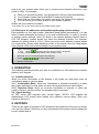
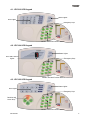
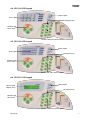
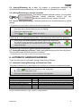
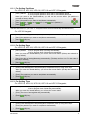
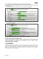
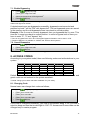
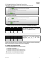
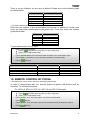
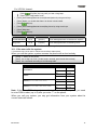
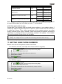
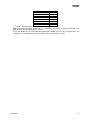
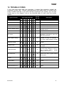
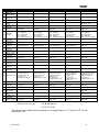
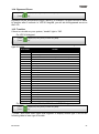
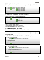
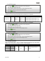
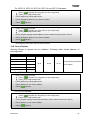
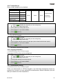
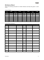
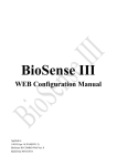
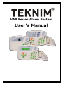
VAP Series Alarm System User’s Manual Issue Date: 13/02/2007 TD-1/07-002 TABLE OF CONTENTS 1. WARNINGS ............................................................................................................ 3 2. INTRODUCTION .................................................................................................... 4 2.1 User types and authorizations ........................................................................... 4 2.2 What can I do with my system........................................................................... 4 2.3 Entering to the addresses and monitoring/changing system settings................ 5 3. OPERATION .......................................................................................................... 5 3.1. Audible Indicators............................................................................................. 5 3.1.1. Confirmation Beep ............................................................................................................5 3.1.2. Rejection Beep: ................................................................................................................5 3.2. Light Indicators ................................................................................................. 5 4. KEYPADS .............................................................................................................. 5 4.1. VPC016 LED Keypad....................................................................................... 6 4.2. VPC104 LED Keypad....................................................................................... 6 4.3. VPC108 LED Keypad....................................................................................... 6 4.4. VPC116 LED Keypad....................................................................................... 7 4.5. VPC132 LED Keypad....................................................................................... 7 4.6. VPC301 LCD Keypad ...................................................................................... 7 5. ARMING/DISARMING ............................................................................................ 9 5.1. Basic Arming/Disarming ................................................................................... 9 5.2. Automatic Arming/Disarming ............................................................................ 9 5.3. Arming/Disarming by a key ............................................................................ 10 5.4. Arming/Disarming by remote controller .......................................................... 10 5.5. Partial Arming/Disarming ............................................................................... 10 5.6. One-Touch Arming ......................................................................................... 10 5.7. Arming/Disarming by Phone .......................................................................... 10 6. AUTOMATIC ARMING/DISARMING ................................................................... 10 6.1. Automatic Arming/Disarming on Determined Time ........................................ 10 6.1.1. For Setting Partitions....................................................................................................... 11 6.1.2. For Setting Days ............................................................................................................. 11 6.1.3. For Setting Time ............................................................................................................. 11 6.1.4. Automatic Arming/Disarming for determined time period.................................................. 12 6.2. Automatic Arming on No Movement ............................................................... 12 7. BYPASSING ........................................................................................................ 12 7.1. Enable Bypassing .......................................................................................... 13 7.2. Cancel Bypassing .......................................................................................... 13 8. ACCESS CODES ................................................................................................. 13 8.1. Changing Code .............................................................................................. 13 8.2. Assigning New User / Removing Current User .............................................. 14 9. USER AUTHORIZATION ..................................................................................... 14 10. REMOTE CONTROL BY PHONE ...................................................................... 15 10.1. If the user calls the system ........................................................................... 16 10.2. If the panel calls the user ............................................................................. 17 11. SETTING USER PHONE NUMBERS ................................................................ 17 BD-1/07-002 1 12. TROUBLE CODES............................................................................................. 19 13. EVENT LOG ....................................................................................................... 20 13.1. Event Table .................................................................................................. 20 13.2. Monitoring and Controlling Event Log .......................................................... 22 14. REPORTS .......................................................................................................... 22 14.1. Armed Zones................................................................................................ 22 14.2. Last Zone that Alarms .................................................................................. 22 14.3. PGM Status .................................................................................................. 22 14.4. Bypassed Zones .......................................................................................... 23 14.5. Troubles ....................................................................................................... 23 15. TESTS ................................................................................................................ 24 15.1. Siren test ...................................................................................................... 24 15.2. PGM test ...................................................................................................... 24 15.3. Central Station Test ..................................................................................... 24 15.4. User Phone Numbers Test ........................................................................... 25 16. MANUAL CONTROL OF PGM OUTPUT ........................................................... 25 17. TIME AND DATE SETTING ............................................................................... 25 17.1. Setting Time ................................................................................................. 25 17.2. Setting Date ................................................................................................. 26 18. KEYPAD INNER SETTINGS .............................................................................. 26 18.1. Chime ........................................................................................................... 26 18.2. Backlight Zones............................................................................................ 27 18.3. Emergency Buttons ...................................................................................... 27 18.4. Sound Options ............................................................................................. 28 18.5. Trouble Beeps .............................................................................................. 29 18.6. Language Selection ..................................................................................... 29 18.7. Thermometer Setting ................................................................................... 29 REFERENCE SHEET............................................................................................... 31 1. Central Station Information: Account#:______________ Telephone#:______________ Note:_______________________ 2. Central Station Information: Account#:______________ Telephone#:______________ Note:_______________________ Installer Information: Company:______________________________ Telephone#:______________ Teknim Elektronik reserves the right to change information on the manuals at any time without notice. BD-1/07-002 2 1. WARNINGS PUBLIC Read this guide carefully before operating device and keep this guide for later reference. Follow all operating and safety instructions in this guide. Keep away devices from dust and moisture. Locate to the straight place in order not to damage device. It is not recommended to make ADSL connection with your alarm panel because ADSL has some features which may prevent communication of alarm panel. It is recommended to use ADSL filter, if ADSL will be connected to your alarm panel. OPERATING CONDITIONS Don’t operate device beyond following values. Temperature: Between 0 C and +65 C Humidity: +40 C in %95 POWER SUPPLY Use device only with voltage mentioned in guide. If you are not sure about supply voltage you will connect, contact with your vendor. GROUNDING Before connecting power supply, control if grounding works properly. SUPPLY CABLE PROTECTION Protect the supply cable against breaking and crushing. CURRENT LIMIT Don’t connect devices that consume current exceeds limits. OVERLOAD In order to avoid from electrical shock or fire risk, do not connect electrical devices which needs over current to the plugs OBJECT and LIQUID ENTRY Never push any kind of objects or liquid into this unit as they may short-out parts that could result in a fire or electrical shock. SERVICE Do not attempt to service this unit yourself as opening or removing covers may expose you to dangerous voltage or other hazards. Refer all servicing to qualified service personnel. CONDITIONS NEED SERVICE Contact with your vendor on the following conditions, If power cable or plug is damaged, If any kind of objects drops into unit, If unit is exposed to water or rain, If unit is dropped or cover is damaged, If you realize that device doesn't work properly, If unit doesn’t operate properly in operating conditions. BD-1/07-002 3 SPARE PART If parts of device are changed to repair, ensure that technician uses original parts against electrical shock, fire, etc. SECURITY CONTROL To control if your device operates in healthy and convenient conditions, demand service from your vendor. 2. INTRODUCTION Thank you for selecting VAP Series Security Systems from Teknim Security Systems. VAP Series Security Systems have been designed for you to provide reliable security protection and your home’s automation. Read this manual carefully and have your installer’s instruction about basic system operation and your system’s features which have been implemented in. Keep this manual in a safe place for later reference. Your system consists of one of Teknim VAP Series Alarm Panels (VAP204, VAP304, VAP308 VAP404, VAP408 or VAP416), one or more Teknim Keypad (VPC016, VPC104, VPC108, VPC116, VPC132 or VPC301) and various devices such as detectors, sensors, sirens… etc. The metal cabinet contains the system electronics, transformer, fuses and battery. There is no reason for anyone except your installer to have access to the control panel. All the keypads allow you to easily access your security system’s functions, to send commands to the system and to display the current system status. 2.1 User types and authorizations There are three user groups in VAP series security systems; 1. Master user; can make some settings (clock and date setting, user phones setting, user codes setting, arming/disarming setting, user authorization setting) in master program and can arm/disarm the system. 2. Normal user; can arm/disarm the system. 3. Guest user; can arm/disarm the system one time or within limited time period. If any user enters invalid codes three times, siren alarms for a while. If the user continues to enter invalid codes, the alarm period of the siren will increase and the keypad will be locked temporary In addition to them, there are also installer code, PC remote control code and duress code. Installer code is used by your installer to make system settings. Installer can not arm/disarm the system and can not access user codes. PC remote control code is allowing you to control your system via VAPMan software. Duress code can be used by the person who is under duress. This code can disarm the system but system calls the CMS. (There is no duress code in VAP204 alarm panel) After your system is installed by authorized installer, a master user code will be given to you to enter master menu. Please change this master code for your security. 2.2 What can I do with my system Your system is not only an alarm system but also a home automation system. You can also use your system as an access control system by assigning authorizations to the users and keypads. In addition to them, there are programmable outputs (PGM BD-1/07-002 4 output) on your system which allow you to control some electrical devices in your home or office. For example; When you armed the system, your garage door can be closed automatically. Your irrigation system can be activated in determined time/day. When there is a fire alarm, the system can active the system of fire fighting. You can active your climate system or your heater by phone* Please ask your installer for details. *This feature can not be used in VAP2xx and VAP3xx alarm panel. 2.3 Entering to the addresses and monitoring/changing system settings Each address is a four digit number. Addresses keep system parameter(s). You can enter to these addresses according to your code’s authorization. In order to monitor or change system settings, when you enter to the related address (related menu in VPC 301 keypad), system shows you what this address includes. For example; address for system clock is <0101>. When you enter to this address, keypad shows you current time. Please make following to enter to the master menu by using master code (default: 1234) and monitor/change current system clock. Enter to the master program. 1st step ; [Enter] (Program) key long until you hear a long beep. 2nd step ; [Enter] Your 4 digit master code. (Default 1234) Wait until you can see that program led is blinking. [Enter] Monitor current time. to enter system clock 3. OPERATION The following section provides you with an introduction to the buttons and indicator lights on your keypad. 3.1. Audible Indicators When you enter information to the keypad, it will guide you with beep tones as confirmation beep or rejection beep. 3.1.1. Confirmation Beep: When any information is entered successfully or when the system switches to a new status or mode, the keypad emits two short beeps. 3.1.2. Rejection Beep: When an incorrect information is entered, or when the system reverts to previous status, the keypad emits a long beep. 3.2. Light Indicators All VAP series LED keypads have colored lights, VPC301 LCD keypad has alphanumeric LCD screen which shows your system’s current status. (See your keypad in Section 4). 4. KEYPADS There are six types of keypads of VAP series security systems to allow you to access your security system’s functions, to send commands to the system and to display the current system status. BD-1/07-002 5 4.1. VPC016 LED Keypad Status Lights Zone Lights Emergency Keys Number Pad and Function Buttons 4.2. VPC104 LED Keypad Status Lights Zone and Function Lights Emergency Keys Number Pad and Function Buttons 4.3. VPC108 LED Keypad Status Lights Zone Lights Emergency Keys Partition and Arrow Keys Number Pad and Function Buttons BD-1/07-002 6 4.4. VPC116 LED Keypad Status Lights Zone Lights Emergency Keys Partition and Arrow Keys Number Pad and Function Buttons 4.5. VPC132 LED Keypad Status Lights Zone Lights Emergency Keys Partition and Arrow Keys Number Pad and Function Buttons 4.6. VPC301 LCD Keypad Liquid Crystal Display (LCD) Status Lights Emergency Keys Partition and Arrow Keys Number Pad and Function Buttons BD-1/07-002 7 Zone Lights: In VPC016, VPC108, VPC116 and VPC132 keypads, numerical leds are designed to show the status of the zones in your system. If a zone light is “OFF”, the corresponding zone is closed. If a zone light is “ON”, the corresponding zone is open (open door, movement detected...etc). In VPC104 keypad, you can see the opened zone in 7 segment LED screen. In VPC301 keypad, the opened zones can be seen in Alphanumeric LCD screen. Status Lights: Status lights are same in all VAP series keypads (VPC016, VPC104, VPC108, VPC116, VPC132 and VPC301) designed to show status of your alarm system. If ready light is “ON”, your alarm system is ready to arm. When you armed the system successfully, “armed” light will be “ON”. If there is a trouble, “trouble” light will be “ON”. “Fire” led will be “ON”, if there is a fire alarm. Number Pads and Function Buttons: Besides normal number pad feature, these buttons provide you some functions to control your system easily. Each button has a second function. To activate second function of the buttons, press long related button until you hear a long beep. Look at the following table to get detailed information about the functions of number pad. Button 1 2 3 4 5 6 7 8 9 0 X √ Main Function “1” “2” “3” “4” “5” “6” “7” “8” “9” “0” Cancel OK Secondary Function Panic. Fire. Duress. Program – To enter programming mode. Bypass. Report. Chime – To open/close chime function. Test. Memory – To display event log. Reset – To disarm fire alarm. Exit. Password – To change code. Partition and Arrow Keys*: These keys are designed to allow you to control partitions of your system. By pressing these keys, you can arm/disarm the required partitions easily. There are also second functions of the keys as you can see on the figures of related keys. A key is for indoor arming/disarming, B key is to arm windows, C key is to arm doors and D key is for outdoor arming/disarming. In order to use second function of these keys, SPT (Smart partition technology)** must be activated. * ** These keys are not active in VAP2xx and VAP3xx alarm panel since there is no partition. Please contact your installer for detailed information. BD-1/07-002 8 Function Lights: In VPC016, VPC108, VPC116, VPC132 keypads, there are also function lights to display power, program, bypass and memory status. If there is a problem related with power, power light will be “OFF”, if you are in master menu, program light will be “ON”. If there is a bypassed zone, bypass light will be “ON” If there is an unread event in event log, memory light will be “ON”. Liquid Crystal Display (LCD): Liquid Crystal Display (LCD) is designed in VPC301 keypad to display you almost all information about your alarm system. You can also see temperature and time/date information on LCD. Light Emitting Display (LED): Light Emitting Display (LED) is designed in VPC104 keypad to display you some information about your alarm system. 5. ARMING/DISARMING “Ready” light must be “ON” to arm the system. Armed light will be “ON” when panel is armed. If exit delay is entered to the system, before arming, the system starts to exit delay to give you enough time to exit the protected area. The keypad emits “beep” sound as entered exit delay time. For example; if 30 seconds is entered as exit delay, keypad emits “beep” sound for 30 seconds*, then it is armed. If system couldn’t be armed, “trouble” light and some zone lights flash to indicate what kind of trouble occurred. Please check the trouble types at troubles codes section. If enter delay is entered to the system, when you enter to the protected area, the system starts to enter delay to give you enough time to enter valid code. The keypad emits “beep” sound* as entered delay time. * At last 4 sec. of the entered time, “beep” sounds will be faster. 5.1. Basic Arming/Disarming: All system or authorized partitions are armed/disarmed by entering 4 digit code for any user. (See user authorization section for authorized partitions) Be sure that “ready” light is “ON” (if you want to disarm the system “armed” light will be “ON”) [Enter] your 4 digit user code. 5.2. Automatic Arming/Disarming: All system or determined partitions are armed/disarmed at determined time of the selected days. (See automatic arming/disarming section for details) BD-1/07-002 9 5.3. Arming/Disarming by a key: All system or determined partitions are armed/disarmed by pressing a key or a button which is connected to key input. 5.4. Arming/Disarming by remote controller This feature requires optional module. If your system includes remote controller module you can arm/disarm system by your remote controller 5.5. Partial Arming/Disarming*: Selected partitions are armed/disarmed by partial arming. * This feature can not be used in VAP2xx and VAP3xx Alarm Panel. [Press] short to the partition/partitions buttons (A,B,C,D) you want to arm (you will hear a short beep and see that pressed buttons will be flashing) [Enter] your 4 digit user code. [Enter] to arm, to disarm the system. 5.6. One-Touch Arming*: Selected partitions are armed by pressing to the partition button (A, B, C, D) without entering code. (You may select more than one partition). [Press] long to the partition/partitions buttons (A,B,C,D) you want to arm You will hear a long beep and see that pressed buttons will be flashing (After 5 seconds, the partitions you selected will be armed. Press “Exit” key to cancel the arming.) * This feature can not be used in VAP2xx and VAP3xx Alarm Panel. 5.7. Arming/Disarming by Phone*: Basic arming/disarming can be done by phone. (See remote control by phone section for details) * This feature can not be used in VAP2xx and VAP3xx Alarm Panel. 6. AUTOMATIC ARMING/DISARMING There are two types of automatic arming / disarming as follows. 6.1. Automatic Arming/Disarming on Determined Time This feature allows you to arm/disarm any partition or all system on determined time Enter to the master program. [Enter] (Program) key long until you hear a long beep. [Enter] your 4 digit master code. [Enter] the related address or menu according to following table. Setting Address LCD Menu Automatic Arming Partitions** 12 01 Panel Settings/Auto Arm/Disarm/Auto Arm Partitions Automatic Arming Days 12 02 Panel Settings/Auto Arm/Disarm/Auto Arm Days Automatic Arming Time 12 03 Panel Settings/Auto Arm/Disarm/Auto Arm Time Automatic Disarming Partitions** 12 04 Panel Settings/Auto Arm/Disarm/Auto Disarm Partitions Automatic Disarming Days 12 05 Panel Settings/Auto Arm/Disarm/Auto Disarm Days Automatic Disarming Time 12 06 Panel Settings/Auto Arm/Disarm/Auto Disarm Time (**)Since there is no partition in VAP2xx and VAP3xx alarm panel, Automatic arming/disarming feature can be activated by selection of the 1 option in related address. BD-1/07-002 10 6.1.1. For Setting Partitions For VPC016, VPC104, VPC108, VPC116 and VPC132 keypads; [Enter] address [Enter] the partitions you want to arm/disarm automatically. [Enter] for A, for B, for C, and for D partition).* [Enter] (Ok) key. 12 01 to program partitions which will be automatically armed 12 04 to program partitions which will be automatically disarmed. When you enter to the related address, you will see the current status. (No partition is selected as factory default) * For VAP2xx and VAP3xx alarm panel, enter “1” to enable this feature. (There is one partition in VAP2xx and VAP3xx, if you enter “1”, all system will be set as automatically armed/disarmed.) For VPC301 keypad; [Enter] Panel Settings/Auto Arm/Disarm/Auto Arm/Disarm Partitions by using arrow keys. [Enter] the partitions you want to arm/disarm automatically. [Enter] (Ok) key. 6.1.2. For Setting Days For VPC016, VPC104, VPC108, VPC116 and VPC132 keypads; [Enter] address 12 02 to program days of arming automatically 12 05 to program days of disarming automatically. When you enter the related address, you will see the current status. (All days are selected as factory default) [Enter] the days of arming/disarming automatically. (The days are from 1 to 7 in the order of Monday to Sunday) [Enter] (Ok) key. For VPC301 keypad; [Enter] Panel Settings/Auto Arm/Disarm/Auto Arm/Disarm Days by using arrow keys When you enter the related address, you will see the current status. (All days are selected as default) [Enter] The partitions you want to arm/disarm automatically [Enter] (Ok) key. 6.1.3. For Setting Time For VPC016, VPC104, VPC108, VPC116 and VPC132 keypads; [Enter] address 12 03 to program time of arming automatically 12 06 to program time of disarming automatically. When you enter the related address, you will see the current status. [Enter] The time of arming/disarming automatically [Enter] (Ok) key. For VPC301 keypad; [Enter] Panel Settings/Auto Arm/Disarm/Auto Arm/Disarm Time by using arrow keys. [Enter] the partitions you want to arm/disarm automatically. [Enter] BD-1/07-002 (Ok) key 11 6.1.4. Automatic Arming/Disarming for determined time period For example, let’s set the system as it will be armed every Tuesday at 19:00 and disarmed at 09:00 For VPC016, VPC104, VPC108, VPC116 and VPC132 keypads; Enter to the master program. [Enter] (Program) key long until you hear a long beep. Your 4 digit master code. Enter address 12 01* and enter to arm all partitions. (Total 4 partitions) Enter address 12 02 and enter to arm the system on Tuesday (The 2nd day of the week is Tuesday) Enter address 12 03 and enter to arm the system at 19:00 Enter address 12 04* and enter to disarm all partitions. (Total 4 partitions) Enter address 12 05 and enter to disarm the system on Tuesday (Tuesday is 2nd day of the week) Enter address 12 06 and enter to disarm the system at 09:00 Enter (Exit) key long until you hear a long beep. * In VAP2xx, VAP3xx alarm panels, enter “1” because there is only a partition. For VPC301 keypad; Enter to the master program. [Enter] (Program) key long until you hear a long beep. Your 4 digit master code. Enter menu “Panel Settings/Auto Arm/Disarm/Auto Arm” and [Enter] (*) to arm all partitions.(A=1, B=2, C=3, D=4) [Enter] to arm the system on Tuesday.(The 2nd day of the week is Tuesday) [Enter] to arm at 19:00 Enter “Panel Settings/Auto Arm/Disarm/Auto Disarm” and [Enter] (*) to disarm all partitions.(A=1, B=2, C=3, D=4) [Enter] to disarm the system on Tuesday.(The 2nd day of the week is Tuesday) [Enter] to disarm the system at 09:00 Enter (Exit) key long until you hear a long beep. * In VAP2xx, VAP3xx alarm panels, enter “1” because there is only a partition. 6.2. Automatic Arming on No Movement If there is no movement on a specific zone for a determined time*, the system will be armed automatically. This feature can be programmed only by installer. Please contact your installer for this feature. * This time can be set by your installer 7. BYPASSING Sometimes, it may be necessary to make some zones "out of service" if there is an error on related zone/zones. For example, if a defected detector prevents to arm the system or causes false alarm, related zone/zones must be made "out of service". This operation is called as bypass. BD-1/07-002 12 7.1. Enable Bypassing [Press] (Bypass) key long. [Enter] your 4 digit user code. Select zone/zones that will be bypassed?1 [Enter] (Ok) key. 1 To enter one digit zone number in keypads VPC016, VPC116, VPC132, please enter "0" then related one digit zone number. If related zone/zones are bypassed successfully, bypassed zone/zones led and partition key leds** will be "ON" with bypass led*. The last bypassed zones are saved in the memory and the old bypassed zones turns back to normal position Example: If the 3rd zone is currently bypassed, then you bypassed the 2 nd zone. This time the 3rd zone turns back to normal position. In order to bypass both of them you have to enter "2", "3" and "bypass" key. * There is no bypass led in VPC 301 LCD keypad. Bypass information can be seen in LCD. ** Partition LEDs are not available on VAP2xx and VAP3xx alarm systems. 7.2. Cancel Bypassing [Press] (Bypass) key long [Enter] your 4 digit user code. [Enter] (Ok) key. Please not that armed zones can not be bypassed. 8. ACCESS CODES According to your system model, there are following codes and authorizations in your system. Model VAP204 VAP304 VAP308 VAP404 VAP408 VAP416 Master 1 1 1 1 1 1 User 5 5 9 5 9 29 Guest 1 1 1 1 1 1 Duress (no) 1 1 1 1 1 Engineer 1 1 1 1 1 1 PC Access 1 1 1 1 1 1 Default codes are; Master code: 1234*, PC Access code: 7777, User, duress and guest codes are not entered to the system as default. * Please change your master code after installation for your safety. 8.1. Changing Code Normal users can change their codes as follows; [Enter] (Program) key long. [Enter] Your current code. [Enter] Your new code. [Enter] Your new code again. [Enter] (Ok) key. If the code is changed successfully, you hear a confirmation beep. If not, you hear a rejection beep and see that trouble light is “ON”. PC Access and Duress code can be changed only in master program. BD-1/07-002 13 8.2. Assigning New User / Removing Current User Only master user can assign a new user and remove the current user. To assign a new user; Enter to the master program. [Enter] (Program) key long until you hear a long beep. Your 4 digit master code. [Enter] Related address or menu from the below table* [Enter] New user code. [Enter] (Ok) key. To remove a current user; Enter to the master program. [Enter] (Program) key long until you hear a long beep. Your 4 digit master code. [Enter] Related address or menu from the below table* [Enter] New user code as “0000”. [Enter] (Ok) key. VPC016, VPC104, VPC108, VPC116 ve VPC132 keypadler için adresler; VAP204 VAP304 VAP308 VAP404 VAP408 VAP416 Guest 07 06 07 06 07 10 07 06 07 10 07 30 Duress 07 07 07 07 07 11 07 07 07 11 07 31 PC Access 07 08 07 08 07 12 07 08 07 12 07 32 User By adding 07 to the user number, user address can be determined. For example; 19th user address is <07 19>, 3rd user address is <07 03> For VPC301 keypad; By entering “Basic settings/User codes” in the menu, it is possible to enter user codes menu. Guest Duress PC Access User VAP204 06 07 08 User number is also number of user code menu. For example; for 19th user, “Basic seetings/User VAP304 06 07 08 codes/19-User code”, for 3rd user, “Basic VAP308 10 11 12 settings/User codes/03-User code VAP404 06 07 08 VAP408 10 11 12 VAP416 30 31 32 * For VPC301 keypad, use arrow keys to select user. Please note that guest code is a temporary code and becomes inactive automatically after one time using or 24 hours from the time of assigning. 9. USER AUTHORIZATION You can give authorization to the users as follows; Authorization for arming/disarming Authorization for bypassing Authorization for using user code for determined time Authorization for using user code for determined days Authorization for controlling determined partitions* Authorization for controlling determined keypads* * These features are not active in VAP2xx and VAP3xx. BD-1/07-002 14 There is no any limitation for any user as default. Please refer to the following table for authorization. Addresses Start Time 40 <user number> Finish Time 41 <user number> Days 42 <user number> Partitions * 43 <user number> Keypads * 44 <user number> Permissions 45 <user number> * This option (address) is not active in VAP2xx and VAP3xx alarm panel. Enter the user number to give authorization to that user. In addition to normal user code, you may make authorization to the guest code. To do that, enter user number given below table. VAP204 VAP304 VAP308 VAP404 VAP408 VAP416 User Number 06 06 10 06 10 30 To give authorization for any user: Enter to the master program. [Enter] (Program) key long until you hear a long beep. [Enter] Your 4 digit master code. [Enter] Related address from the above table according to the authorization type.* [Enter] Data or permission. (if you will enter permission, see below table). [Enter] (Ok) key. Options On / Active Off / Inactive 1. Option Can’t arm the system Can arm the system 2. Option Can’t disarm the system Can disarm the system 3. Option (only for guest code) One time use active One time use inactive 4. Option (only for guest code) Daily use active Daily use inactive 5. Option Can’t be bypassed Can be bypassed * For VPC301 keypad, Enter User Settings and use arrow keys to select related authorization type. 10. REMOTE CONTROL BY PHONE * This feature can not be used in VAP2xxx and VAP3xx alarm panel. In order to communicate with your security system by phone, this feature must be activated. To activate the system. For VPC016, VPC104, VPC108, VPC116 and VPC132 keypads; Enter to the master program [Enter] (Program) key long until you hear a long beep. [Enter] your 4 digit master code. [Enter] address 15 01 and select option 1 as shown in below table. [Enter] [Enter] address 15 02 and enter ring time for the system before answering the phone. [Enter] BD-1/07-002 (Ok) key. (Ok) key. 15 For VPC301 keypad; Enter to the master program [Enter] (Program) key long until you hear a long beep. [Enter] your 4 digit master code. [Enter] Panel Settings/Remote Access/Remac Options by using arrow keys. [Enter] Option 1 to enable this feature as shown in below table. [Enter] [Enter] Panel Settings/Remote Access/Ring Count by using arrow keys. [Enter] Ring time. [Enter] (Ok) key. (Ok) key. Option Address Enabled/Disabled 15 01 Ring Time 15 02 Default Value Enabled (option1) 5 (times) LCD Menu Panel Settings/Remote Access/Remac Options Panel Settings/Remote Access/Ring Count There are two ways of communication with your system; 10.1. If the user calls the system * This feature can not be used in VAP2xxx and VAP3xx alarm panel. When you call the system, system answers the phone with a short melody. [Press] “*” button on the phone [Enter] Your 4 digit user code. (If valid code is entered, panel sends short melody) [Enter] Your commands according to the following table. Option Arm/Disarm PGM1 PGM2(There is no this PGM in VAP2xx, VAP3xx) PGM3(There is no this PGM in VAP2xx, VAP3xx, VAP404) Command Buttons Disarm *00# Arm *01# Off *10# On *11# Off *20# On *21# Off *30# On *31# Note: If there is a PGM relay output module is connected to your system, you need to enter PGM number (up to 8) after you enter "*" on the phone. When you call your system, you may get information from your system about its current status as follows. BD-1/07-002 16 Command Arm/Disarm Status. *0# PGM1 Status *1# PGM2(There is no this PGM in VAP2xx, VAP3xx) *2# PGM3(There is no this PGM in VAP2xx, VAP3xx, VAP404) *3# Status Confirmation Armed 2 short beep Disarmed 1 long beep PGM1 On 2 short beep PGM1 Off 1 long beep PGM2 On 2 short beep PGM2 Off 1 long beep PGM3 On 2 short beep PGM3 Off 1 long beep Note: If there is a PGM relay output module is connected to your system, you need to enter PGM number (up to 8) after you enter "*" on the phone. 10.2. If the panel calls the user During alarm, your system calls the stored phone numbers in your system orderly. If called user does not answer the phone or does not enter correct code, the same user is called for 3 times. Then, other user phones in the system memory are called orderly until the correct code is entered. When user answers the phone, user hears a signal tone or message (if there is a message module in the system). Your installer may limit the phone number which will be called [Press] “*” button on the phone [Enter] Your 4 digit user code.1 (If valid code is entered, panel sends short melody) (1) If installer configures system, user can answer phone by only pressing “*”. 11. SETTING USER PHONE NUMBERS Master user can set user phone numbers as follows. For VPC016, VPC104, VPC108, VPC116 and VPC132 keypads; Enter to the master program. [Enter] (Program) key long until you hear a long beep. [Enter] Your 4 digit master code. [Enter] One of following address that you want to set. [Enter] phone number* [Enter] (Ok) key. For VPC301 keypad; Enter to the master program. [Enter] (Program) key long until you hear a long beep. [Enter] Your 4 digit master code. [Enter] Basic Settings/Private Phone Numbers by using arrow keys. [Enter] Phone number* [Enter] BD-1/07-002 (Ok) key. 17 User Phones Address User Phone-1 06 01 User Phone-2 06 02 User Phone-3 06 03 User Phone-4 06 04 User Phone-5 06 05 User Phone-6 06 06 User Phone-7* 06 07 User Phone-8* 06 08 * 7th and 8th user phones are available only on VAP416 Note: User phone numbers can be from 3 to 15 digits. If you want to cancel a number which has been already entered, please enter "0" long. If you will telephone line from telephone switchboard, please long "0" long to get dial tone. For example, if you will get dial tone with "9", please enter "9" then enter "0" long. BD-1/07-002 18 12. TROUBLE CODES If you hear long beep after any operation, it means that operation couldn’t be confirmed. At this time “Trouble” light and some zone lights flash to indicate what kind of trouble occurred. If you have VPC301 keypad on your system, you can see trouble type on the display. Look at the following table to learn what the trouble means. Type of Trouble Zone lights (VPC108) 1 2 3 4 5 6 7 8 016,104 116,132 Description Invalid address 1 Invalid address has been entered Invalid data 2 Entered data is invalid No permission 3 Your permissions are limited Panel can not be armed 4 There is an opened zone Panel is already armed 5 The partitions you try to arm are already armed Invalid Code 6 Invalid code has been entered Out of limit 7 Entered value is out of limit. For example; if you enter a value over than 23 for the time Type of data is wrong 8 Length of data that you have entered is wrong. For example; if you enter 2 digits instead of 4 digits Feature is closed 9 Feature you have tried to use is closed Invalid function 10 The function you are trying to use is invalid Invalid parameter 11 The parameter you are trying to use is invalid. Example: If you try to test 3.Central Station, keypad displays this trouble Out of time limit 12 If user is trying to use keypad out of his/her time limit, keypad displays this trouble Not allowed in this keypad 13 User is not allowed in this keypad Invalid setting 14 The setting you have made is invalid Unknown trouble 15 Trouble is not known Communication error 16* Keypad can’t communicate with panel * In VPC104 keypad, this error is seen as “C” character. BD-1/07-002 19 13. EVENT LOG Panel keeps last 255 events in its memory. Event logs include event code, event time, event parameters. Type of data in event memory is in the following: VPC016, 108, 116, 132 CC DD HH MM A B VPC104 H CC DD NN YY HH MM A B VPC301 DD NN YY HH MM A B CC: Event Code H: Memory A, B: Additional Data look at following table DD: Day of Event NN: Month YY: Year HH, MM: Time of Event (HH= hour, MM= minutes) In VPC016, VPC104, VPC108, VPC116 and VPC132 keypads, this can be monitored with LEDs and in VPC104 keypad, it is seen with 7 segment display LED. 13.1. Event Table The meanings of "A" and "B" parameters can be different for each model of security systems. These parameters may have unique meaning if they are using alone (only "A" or only "B" parameter) and they may have different meanings if they are using together "[AB]" Please see following table to see the meanings of these parameters. Meaning VAP204 VAP3xx VAP404 VAP408 VAP416 1 Intruder Alarm [AB]:Zone [AB]:Zone [AB]:Zone [AB]:Zone [AB]:Zone 2 Panic Alarm A:Keypad,B:Zone A:Keypad,B:Zone A:Keypad,B:Zone A:Keypad,B:Zone [AB]:Zone 3 Fire Alarm A:Keypad,B:Zone A:Keypad,B:Zone A:Keypad,B:Zone A:Keypad,B:Zone [AB]:Zone 4 Duress Alarm A:Keypad,B:Zone A:Keypad,B:Zone A:Keypad,B:Zone A:Keypad,B:Zone [AB]:Zone A:Keypad,B:Zone A:Keypad,B:Zone A:Keypad,B:Zone A:Keypad,B:Zone [AB]:Zone A:Keypad,B:Zone A:Keypad,B:Zone A:Keypad,B:Zone A:Keypad,B:Zone [AB]:Zone - - - - - [AB]:User [AB]:User [AB]:User [AB]:User [AB]:User 5 6 7 8 Sabotage Alarm Medical Alarm Disarm by Duress Cancel on Disarm 9 Zone Trouble [AB]:Zone [AB]:Zone [AB]:Zone [AB]:Zone [AB]:Zone 10 AC Fail - - - - - - - - - - - - - - - 11 12 Intrusion Verified Cross Zone Fault 13 Battery Low - - - - - 14 Line Fail - - - - - 15 Battery Fail - - - - - Communication Fail [AB]:Phone Order ID 91:Only Call 92:Call+DTMF [AB]:Phone Order ID 91:Only Call 92:Call+DTMF [AB]:Phone Order ID 91:Only Call 92:Call+DTMF [AB]:Phone Order ID 91:Only Call 92:Call+DTMF 17 Special disarmed A:3(Automatic), B:A:4(Key) , B:A:7(Remote Ctrl.), B:- A:3(Automatic), B:A:4(Key) , B:A:7(Remote Ctrl.), B:- A:1(Quick Arm), B:Part. A:3(Automatic), B:A:4(Key) , B:A:5(Phone), B:A:7(Remote Ctrl.), B:- [AB]:Phone Order ID 91:Only Call 92:Call+DTMF A:1(Quick Arm), B:Part. A:3(Automatic), B:A:4(Key) , B:A:5(Phone), B:A:7(Remote Ctrl.), B:A:8(PC), B:- 18 Disarmed [AB]:User [AB]:User [AB]:User [AB]:User [AB]:User 19 Bypassed [AB]:Zone [AB]:Zone [AB]:Zone [AB]:Zone [AB]:Zone A:Keypad A:Keypad A:Keypad A:Keypad A:Keypad - - - - - - - - - - 16 20 21 22 Entering Program Exiting Program Periodic Report BD-1/07-002 A:4(Quick Arm), B:Part. A:6(Automatic), B:A:7(Key) , B:A:8(Remote Ctrl.), B:- 20 Meaning VAP204 VAP3xx VAP404 VAP408 VAP416 23 Panel Restarted - - - - - 24 Manual Report - - - - - 25 Phone Disarmed - - - - [AB]:User 26 PC Disarmed - - - - [AB]:User - - - - [AB]:User 99: PC Access - - - - - [AB]:Zone [AB]:Zone [AB]:Zone [AB]:Zone [AB]:Zone A=0: Keypad A=1: VAPMan B=1: Passwords B=2: Settings B=3: Password+Setting A=0: Keypad A=1: VAPMan B=1: Passwords B=2: Settings B=3: Password+Setting A=0: Keypad A=1: VAPMan B=1: Passwords B=2: Settings B=3: Password+Setting A=0: Keypad A=1: VAPMan B=1: Passwords B=2: Settings B=3: Password+Setting A=0: Keypad A=1: VAPMan B=1: Passwords B=2: Settings B=3: Password+Setting [AB]:Zone [AB]:Zone [AB]:Zone [AB]:Zone [AB]:Zone A:Keypad,B:Zone A:Keypad,B:Zone A:Keypad,B:Zone A:Keypad,B:Zone [AB]:Zone A:Keypad,B:Zone A:Keypad,B:Zone A:Keypad,B:Zone A:Keypad,B:Zone [AB]:Zone A:Keypad,B:Zone A:Keypad,B:Zone A:Keypad,B:Zone A:Keypad,B:Zone [AB]:Zone A:Keypad,B:Zone A:Keypad,B:Zone A:Keypad,B:Zone A:Keypad,B:Zone [AB]:Zone A:Keypad,B:Zone A:Keypad,B:Zone A:Keypad,B:Zone A:Keypad,B:Zone [AB]:Zone [AB]:Zone [AB]:Zone [AB]:Zone [AB]:Zone [AB]:Zone - - - - - - - - - - - - - - - - - - - - A:2(No Activity), B:A:3(Automatic), B:A:4(Key) , B:A:7(Remote Ctrl.), B:- A:1(Quick Arm), B:Part. A:2(No Activity), B:A:3(Automatic), B:A:4(Key) , B:A:5(Phone), B:A:7(Remote Ctrl.), B:- A:1(Quick Arm), B:Part. A:2(No Activity), B:A:3(Automatic), B:A:4(Key) , B:A:5(Phone), B:A:7(Remote Ctrl.), B:A:8(PC), B:- A:4(Quick Arm), B:Part. A:5(No Activity), B:A:6(Automatic), B:A:7(Key) , B:A:8(Remote Ctrl.), B:- 27 28 30 32 33 34 35 36 37 38 41 42 45 46 47 Remote Access Begin Parallel Line Actived Custom Alarm Defaults Loaded Intruder Alarm Restored Panic Alarm Restored Fire Alarm Restored Duress Alarm Restored Sabotage Alarm Restored Medical Alarm Restored Zone Trouble Restored AC Restored Battery Restored Phone Line Restored Battery Restored 49 Special Arming A:2(No Activity), B:A:3(Automatic), B:A:4(Key) , B:A:7(Remote Ctrl.), B:- 50 Alarm Armed [AB]:User [AB]:User [AB]:User [AB]:User [AB]:User 51 Bypass Canceled [AB]:Zone [AB]:Zone [AB]:Zone [AB]:Zone [AB]:Zone 57 Phone Armed - - - - [AB]:User 58 PC Armed - - - - [AB]:User - - - - [AB]:User 99:PC Access - - - - - [AB]:Zone [AB]:Zone [AB]:Zone [AB]:Zone [AB]:Zone 59 60 62 Remote Access End Parallel Line Inactived Custom Zone Alarm Restored For example, if VPC108 keypad displays 0-1-1-5-2-1-3-6-0-1 that means as following VPC016, 108, 116, 132 CC DD HH MM A B 01 15 21 36 01 The above event code shows that there is a burglar alarm in 1st zone on 15th of the month at 21:36. BD-1/07-002 21 13.2. Monitoring and Controlling Event Log For VPC104 keypad; [Press] (Memory) key long until you hear long beep. You will see “h” on the LED display, and then you will see the event by digits in order. [Press] key to go forward and [Press] key to go back in event memory. [Press] (Exit) key long to exit from event log. For VPC016, VPC104, VPC108, VPC116 and VPC132 keypads; [Press] (Memory) key long until you hear long beep. “Power” light starts flashing and keypad displays last event. Keypad reads event by digits in order. After reading event, all zone lights start flashing to inform reading of the event has finished then keypad displays that event again. [Press] ”A” button to go forward and [Press] “D” button to go back in event memory. [Press] (Exit) key long to exit from event log. For VPC301 keypad; [Press] (Memory) key long until you hear long beep. You can see the last event on the LCD [Press] ”A” button to go forward and [Press] “D” button to go back in event memory. [Press] (Exit) key long to exit from event log. 14. REPORTS 14.1. Armed Zones [Press] (Report) key long until you hear long beep. [Press] key. Armed zones and partitions begin flashing with armed light (if available). Keypad returns standby position after 5 seconds. In VPC301 keypad, you will see the armed zones on the LCD. 14.2. Last Zone that Alarms [Press] (Report) key long until you hear long beep. [Press] key. Keypad displays last zone and partition that alarms. 14.3. PGM Status [Press] [Press] (Report) key long until you hear long beep. key. Keypad displays PGM status. BD-1/07-002 22 14.4. Bypassed Zones [Press] (Report) key long until you hear long beep. [Press] key. Bypassed zones and partitions begin flashing (If available). Keypad returns to stand by position after 5 seconds. In VPC301 keypad, you will see the bypassed zones on the LCD. 14.5. Troubles If there is a trouble on your system, “trouble” light is “ON”. For VPC104 Keypad: [Press] (Report) key long until you hear long beep. [Press] key. You will see “t” letter than a code for each trouble. Look at the following table to learn type of trouble. Arıza Kodu t1 t2 t3 t4 t5 t6 t9 t10 t11 t12 t13 t14 t15 t16 t17 t18 t19 t20 t21 t22 t23 t24 C Anlamı Power loss or mains failure. Low battery. Time and date must be entered (Set time and date) Telephone line failure Zone failure Battery failure. Zone 1 open-circuit Zone 1 short-circuit Zone 2 open-circuit Zone 2 short-circuit Zone 3 open-circuit Zone 3 short-circuit Zone 4 open-circuit Zone 4 short-circuit Zone 5 open-circuit Zone 5 short-circuit Zone 6 open-circuit Zone 6 short-circuit Zone 7 open-circuit Zone 7 short-circuit Zone 8 open-circuit Zone 8 short-circuit There is no communication between keypad and panel For VPC016, VPC104, VPC108, VPC116 and VPC132 keypads; [Press] (Report) key long until you hear long beep. [Press] key. “Trouble” and some other lights flash together to display trouble type. Look at the following table to learn type of trouble. BD-1/07-002 23 Flashing Light Power Program Bypass Memory Trouble and Zone light Description AC Fail (Look at following Trouble) If “Program” light flashes together with “Power” light, battery is in low level Time/Date Trouble Phone Line Fail Flashing zone/zones has wiring program For VPC301 keypad; [Press] (Report) key long until you hear long beep. [Press] key. Trouble type will be seen on LCD screen. [Press] “Exit” button long to return back standby mode. When any new trouble occurs, keypad returns trouble mode again. 15. TESTS PGMs, user phone numbers and CMS can be tested during the alarm system is standby mode. 15.1. Siren test [Press] (Test) key long until you hear long beep. [Press] key and then key. Siren alarms for 5 seconds. 15.2. PGM test [Press] [Press] (Test) key long until you hear long beep. and then key (for PGM1) key (for PGM2)* key (for PGM3)** * There is no PGM2 in VAP2xx, VAP3xx. ** There is noPGM3 in VAP2xx, VAP3xx and VAP404. The selected PGM is activated for 5 seconds. 15.3. Central Station Test There is no this test in VAP204 alarm panel. [Press] (Test) key long until you hear long beep. [Press] and then key (for central. station 1) key (for central. station 2)(*) key (for secondary number of central. station 1)(**) key (for secondary number of central. station 2) (**) * CMS secondary number is tested in VAP304 Alarm Panel. ** Not active in VAP304 Alarm Panel. Panel sends test code to Central Station. BD-1/07-002 24 15.4. User Phone Numbers Test System calls user and sends alarm tone. Answer phone then [Press] “*” and enter your code. [Press] (Test) key long until you hear long beep. [Press] and then key (for user phone-1) key (for user phone-2) key (for user phone-3) : : 16. MANUAL CONTROL OF PGM OUTPUT User can control status of PGM(s) outputs manually. [Press] (Test) key long until you hear long beep. [Press] and then key (for PGM1) key (for PGM2)* key (for PGM3)** : : * There is no PGM2 in VAP2xx, VAP3xx. ** There is noPGM3 in VAP2xx, VAP3xx and VAP404. PGM changes its position (ON→OFF, OFF→ON). 17. TIME AND DATE SETTING Master user can set time and date according to following table. Address 01 01 01 02 Time Date Sample For 9:05 enter 0905. 12/05/2004(dd/mm/yyyy) enters 120504. LCD Menu Basic Settings/Clock Setting/Time Basic Settings/Clock Setting/Date 17.1. Setting Time For VPC016, VPC104, VPC108, VPC116 and VPC132 keypads; Enter to the master program. [Enter] (Program) key long until you hear a long beep. [Enter] Your 4 digit master code. [Enter] address 01 01. [Enter] Time as shown above table. [Enter] (Ok) key. For VPC301 keypad; Enter to the master program. [Enter] (Program) key long until you hear a long beep. [Enter] Your 4 digit master code. [Enter] Basic Settings/Clock Setting/Time. [Enter] Time as shown above table. [Enter] BD-1/07-002 (Ok) key. 25 17.2. Setting Date For VPC016, VPC104, VPC108, VPC116 and VPC132 keypads; Enter to the master program. [Enter] (Program) key long until you hear a long beep. [Enter] Your 4 digit master code. [Enter] Address 01 02. [Enter] Date as shown above table. [Enter] (Ok) key. For VPC301 keypad; Enter to the master program. [Enter] (Program) key long until you hear a long beep. [Enter] Your 4 digit master code. [Enter] Basic Settings/Clock Setting/Date. [Enter] Date as shown above table. [Enter] (Ok) key. 18. KEYPAD INNER SETTINGS * These settings can not be done in VPC104 keypad. Keypad keeps these settings in its memory so configure these settings on which keypads settings you want to change. 18.1. Chime Chime is activated when zone is opened or when zone is closed: Operation Open Chime Close Chime VPC108 99 01 99 02 VPC016-116 VPC132 VPC301 99 01(1-8 zone) Keypad setting/Customize/Chime on 1-8 99 01(1-8 zone) 99 02(9-16 zone) Keypad setting/Customize/Chime on 9-16 99 02(9-16 zone) 99 03(17-24 zone) Keypad setting/Customize/Chime on 17-24 99 04(25-32 zone) Keypad setting/Customize/Chime on 25-32 99 05(1-8 zone) Keypad Setting/Customize/Chime off 1-8 99 03(1-8 zone) 99 06(9-16 zone) Keypad Setting/Customize/Chime off 9-16 99 04(9-16 zone) 99 07(17-24 zone) Keypad Setting/Customize/Chime off 17-24 99 08(25-32 zone) Keypad Setting/Customize/Chime off 25-32 For VPC016, VPC104, VPC108, VPC116 and VPC132 keypads; Enter to the master program. [Enter] (Program) key long until you hear a long beep. [Enter] Your 4 digit master code. [Enter] Address by looking table above. [Enter] Zone number you want to active chime feature. [Enter] BD-1/07-002 (Ok) key. 26 For VPC301 keypad; Enter to the master program. [Enter] (Program) key long until you hear a long beep. [Enter] Your 4 digit master code. [Enter] Keypad setting/Customize/Chime...(select releted chime option). [Enter] Zone number you want to active chime feature. [Enter] (Ok) key. 18.2. Backlight Zones Keypad can activate keypad backlight when selected zone is opened. Option VPC108 Backlight Zones 99 03 VPC016,116 VPC132 VPC301 99 09(1-8 zone) Keypad setting/Customize/Light Z. 1-8 99 05(1-8 zone) 99 10(9-16 zone) Keypad setting/Customize/Light Z. 9-16 99 06(9-16 zone) 99 11(17-24 zone) Keypad setting/Customize/Light Z. 17-24 99 12(25-32 zone) Keypad setting/Customize/Light Z. 25-32 For VPC016, VPC104, VPC108, VPC116 and VPC132 keypads; Enter to the master program. [Enter] (Program) key long until you hear a long beep. [Enter] Your 4 digit master code. [Enter] Address by looking table above. [Enter] Zone number you want to active backlight feature. [Enter] (Ok) key. For VPC301 keypad; Enter to the master program. [Enter] (Program) key long until you hear a long beep. [Enter] Your 4 digit master code. [Enter] Keypad setting/Customize/Light...(select releted backlight option). [Enter] Zone number you want to active backlight feature. [Enter] (Ok) key. 18.3. Emergency Buttons Users can activate “Panic”, “Fire” or “Duress” alarms by pressing long single button Master user can disable secondary functions of these buttons. Button Option Panic (1) 1. Option Fire (2) 2. Option Duress (3) 3. Option Tamper (4) 4. Option BD-1/07-002 VPC108 VPC016,116 VPC132 99 04 99 07 99 13 VPC301 Keypad setting/Customize/ Buttons 27 For VPC016, VPC104, VPC108, VPC116 and VPC132 keypads; Enter to the master program. [Enter] (Program) key long until you hear a long beep. [Enter] Your 4 digit master code. [Enter] Address by looking table above. [Enter] Emergency button no you want to inactive. [Enter] (Ok) key. For VPC301 keypad; Enter to the master program. [Enter] (Program) key long until you hear a long beep. [Enter] Your 4 digit master code. [Enter] Keypad setting/Customize/Buttons (select releted emergency button option). [Enter] Emergency button no you want to inactive. [Enter] (Ok) key. * All emergency buttons are active as factory default. 18.4. Sound Options Warning Beeps of keypad can be disabled. Following table shows address of warning beeps. Beeps Option Exit delay beep 1.option Arm beep 2.option Alarm beep 3.option Trouble beep 4.option Button click 5.option Confirmation beep 6.option VPC108 VPC016,116 VPC132 99 05 99 08 99 14 VPC301 Keypad setting/Customize/ Sound Option For VPC016, VPC104, VPC108, VPC116 and VPC132 keypads; Enter to the master program. [Enter] (Program) key long until you hear a long beep. [Enter] Your 4 digit master code. [Enter] Address by looking table above. [Enter] Options no you want to disable. [Enter] (Ok) key. For VPC301 keypad; Enter to the master program. [Enter] (Program) key long until you hear a long beep. [Enter] Your 4 digit master code. [Enter] Keypad setting/Customize/Sound Option (select releted sound button option). [Enter] Options no you want to disable. [Enter] (Ok) key. * All beeps are active as factory default. BD-1/07-002 28 18.5. Trouble Beeps Some trouble beeps can be disabled. Beeps Option AC Fail 1.option Low Battery 2.option Time/Date Loss 3.option Phone Line Fail 4.option Zone Trouble 5.option Battery Loss 6.option VPC108 VPC016,116 VPC32 VPC301 Keypad setting/ 99 06 99 09 99 15 Customize/ Trouble Optn For VPC016, VPC104, VPC108, VPC116 and VPC132 keypads; Enter to the master program. [Enter] (Program) key long until you hear a long beep. [Enter] Your 4 digit master code. [Enter] Address by looking table above. [Enter] Options no you want to disable. [Enter] (Ok) key. For VPC301 keypad; Enter to the master program. [Enter] (Program) key long until you hear a long beep. [Enter] Your 4 digit master code. [Enter] Keypad setting/Customize/Trouble Optn (select releted trouble button option). [Enter] Options no you want to disable. [Enter] (Ok) key. * All beeps are active as factory default. 18.6. Language Selection * This feature is active only in VPC301 keypad. Language of LCD screen can be configured; Enter to the master program. [Enter] (Program) key long until you hear a long beep. [Enter] Your 4 digit master code. [Enter]Keypad Setting/Customize/Language. [Enter] Options no you want to disable. [Enter] (Ok) key. 18.7. Thermometer Setting * This feature is active only in VPC301 keypad. There is a thermometer in VPC301 keypad. If you think that temperature shown by keypad is not correct, you may calibrate the thermometer. Before calibration, be sure that you measure the real temperature. BD-1/07-002 29 Formulation: RT: Real temperature KT: Temerature is monitored in the keypad CV: Calibration value seen on the keypad (“Keypad Settings/Custumize/Temp Calib.”) EV: The value which will be entered (“Keypad Settings/Custumize/Temp Calib.”) EV= CV + (RT - KT) For example: Assume that real temperature is 21 C, monitored temperature on the keypad is 19 C and calibration value on the keypad is 10. Let’s calculate the calibration value which will be entered: EV = CV + (RT - KT) EV = 10 + (21 - 19) EV = 12 Enter to the master program. [Enter] (Program) key long until you hear a long beep. [Enter] Your 4 digit master code. [Enter] Keypad Setting/Customise/Temp Calib. [Enter] the calculate value by using number pad [Enter] BD-1/07-002 (Ok) key. 30 Reference Sheet Fill out the following information for further reference and keep this guide in a safe place. Access Codes Access Code Code 1 2 3 4 5 6 7 8 Access Code 9 10 11 12 13 14 15 16 Code Access Code 17 18 19 20 21 22 23 24 Code Access Code 24 26 27 28 29 30 31 32 Code Sensor/Zone Information Sensor Protected Area Sensor Type Sensor 1 17 2 18 3 19 4 20 5 21 6 22 7 23 8 24 9 25 10 26 11 27 12 28 13 29 14 30 15 31 16 32 BD-1/07-002 Protected Area Sensor Type 31 BD-1/07-002 32 BD-1/07-002 33 BD-1/07-002 34 http://www.teknim.com BD-1/07-002 35