1
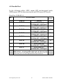
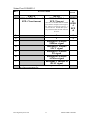
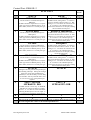
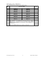
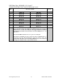
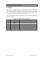
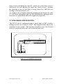
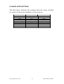
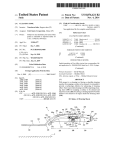
ELAN DIGITAL SYSTEMS LTD.
LITTLE PARK FARM ROAD,
SEGENSWORTH WEST,
FAREHAM,
HANTS. PO15 5SJ.
TEL: (44) (0)1489 579799
FAX: (44) (0)1489 577516
e-mail: [email protected]
website: http://www.pccard.co.uk
SP230 PC-CARD
USER’S GUIDE
All Trademarks are duly acknowledged.
REVISION HISTORY
ISSUE
PAGES
DATE
NOTES
1
2
21
21
23.04.2002
15.05.2002
FIRST ISSUE
Typo correction pg12 bit2/3, pg16 pin17
Elan Digital Systems Ltd.
1
SP230 USER’S GUIDE
Table of Contents
1. OVERVIEW ........................................................................................................................................ 3
2. ABOUT THE SP230 ......................................................................................................................... 4
3. INSTALLING THE SP230................................................................................................................ 6
3.1 DOS & WINDOWS 3.1X, NT4 ............................................................................................................. 6
3.2 WINDOWS 95, 98, 98SE, ME, 2000, XP.............................................................................................. 6
3.3 WINDOWS CE, POCKETPC .................................................................................................................. 8
4. SP230 REGISTER INTERFACE .................................................................................................... 9
4.1 SERIAL PORT ....................................................................................................................................... 9
4.2 PARALLEL PORT ................................................................................................................................ 10
5. HARDWARE SPECIFICATION .................................................................................................... 15
5.1 PINOUT ........................................................................................................................................... 15
5.2 ELECTRICAL.................................................................................................................................. 17
5.3 POWER CONSUMPTION .............................................................................................................. 17
5.4 MECHANICAL................................................................................................................................ 17
5.5 ENVIRONMENTAL........................................................................................................................ 17
5.6 NOTES ON SERIAL DATA THROUGHPUT................................................................................ 17
5.7 SP230 MODE CONFIGURATION ................................................................................................. 18
5.8 BAUD RATE SETTINGS................................................................................................................ 19
APPENDIX A EPP MODE.................................................................................................................. 20
DISCLAIMER
This document has been carefully prepared and checked. No responsibility can be
assumed for inaccuracies. Elan reserves the right to make changes without prior notice
to any products herein to improve functionality, reliability or other design aspects. Elan
does not assume any liability for loses arising out of the use of any product described
herein; neither does it convey any license under its patent rights or the rights of others.
Elan does not guarantee the compatibility or fitness for purpose of any product listed
herein. Elan products are not authorized for use as components in life support services
or systems. Elan should be informed of any such intended use to determine suitability of
the products.
Source code supplied with Elan PC-Cards and Compact Flash cards is provided “as-is”
with no warranty, express or implied, as to its quality or fitness for a particular purpose.
Elan assumes no liability for any direct or indirect losses arising from use of the
supplied code.
Copyright © 2002 Elan Digital Systems Ltd.
Elan Digital Systems Ltd.
2
SP230 USER’S GUIDE
1. OVERVIEW
The SP230 is a multifunction RS232 Serial and IEEE1284 Parallel
Port PC-Card with the following features:
• Industry standard RS232 COM port with 16550 UART
• IEEE1284 Parallel Port featuring SPP Uni-directional, SPP Bidirectional and EPP Modes
• Windows 95 (osr2), 98, 98SE, Me, 2000, XP compatible using
standard O.S. drivers
• Serial data rates up to 921KBaud using x8 baud rate mode
• Full hardware modem control line support on COM port
• Standard decode for COM1 to COMn, and LPT1, 2 or 3
• “Any” IO port and interrupt decode option for best pnp flexibility
• ESD protected RS232 and Parallel Port drivers
• Low power consumption, 5V operation
• Supplied with 300mm cable with DB9-male using “standard”
COM port pin-out and DB25-female with standard LPT port pinout
This guide aims to familiarize you with the way that the SP230
works and so will help you to maximize its performance in your
application.
Elan will be happy to quote for either customization of the SP230 if
its exact specifications do not quite meet your needs, or to create
complete application software.
Elan Digital Systems Ltd.
3
SP230 USER’S GUIDE
2. ABOUT THE SP230
Serial Port:
The SP230 PC-Card provides an RS232 serial port, which uses
Elan’s own 16550 compatible UART ASIC device, called the
VPU16550. The serial data and control lines are buffered using ESD
protected RS232 drivers, which feature an auto power-down mode
when the RS232 cable is not connected.
Industry standard baud rates up to 115.2K baud are supported,
together with 16-byte deep TX and RX FIFOs. Additionally, the
SP230 can be set to multiply the baud rates by 8, allowing up to
921KBaud to be used. The faster rates are transparent to the O.S. so
you’ll have to remember to multiply the rate you set in software by 8
to tell you what the real hardware rate is e.g. if you set 19200baud in
software, and you select x8 mode, the real rate will be 153600baud.
For further information please refer to the VPU16550 data sheet
available from our website, http://www.pccard.co.uk
Parallel Port:
The SP230 follows the IEEE1284 standard to offer 3 modes of
operation:
1. Uni-directional SPP mode. This mode is closest to the legacy
“Centronics” mode as was found on the original IBM AT printer
adapter. The 8 data lines are output only, and certain of the
output control lines use open-drain drivers with 4.7KOhm pullups. This mode can also be known as “nibble” mode because the
only way to input data is via the 4 input status lines.
2. Bi-directional SPP mode. This mode is identical to unidirectional SPP mode except that a previously unused register bit
is now used to tri-state the 8 data line output drivers, allowing
data to be read in, and the open-drain drivers become “normal”
totem pole outputs (the 4.7KOhm resistors become disabled in
this mode). Having the bi-directional data port offers a great
improvement in transfer speed for equipment that must
communicate data in both directions.
3. EPP mode. This mode preserves all the same features as Bidirectional SPP mode but also adds extra IO ports to allow data
handshaking to occur automatically with the connected device.
Elan Digital Systems Ltd.
4
SP230 USER’S GUIDE
This offers a large increase in data throughput capability. To use
EPP mode may require special drivers, as Windows’ support is
limited. EPP mode is described in Appendix A. The SP230 only
supports EPP1.9 mode (EPP1.7 mode was superseded by EPP1.9
mode).
Elan Digital Systems Ltd.
5
SP230 USER’S GUIDE
3. INSTALLING THE SP230
3.1 DOS & Windows 3.1x, NT4
The SP230 is not suited to use in DOS or Windows 3.1x because it
is a true multi-function PC-Card. 3rd party Card and Socket Services
drivers for such cards do not exist (multi-function cards were
defined sometime during Windows95 roll-out and correspondingly
DOS drivers were not updated and were left to support only single
function cards). This is simply a function of available software and
is NOT a shortcoming of the SP230 hardware.
A similar situation is found with Windows NT4 although it is more
likely that 3rd party tools may exist to support this O.S.
3.2 Windows 95, 98, 98SE, Me, 2000, XP
The “generic” serial and parallel drivers in these Operating Systems
support the SP230. No extra driver software is needed but you will
need to install Card Center Pro to get the SP230 registered with the
O.S. Simply run SETUP and follow the instructions given. Note
that you must reboot the PC after installation, to allow the com and
lpt ports to be assigned port numbers by the O.S.
Note that for Win9x and Me the port numbers assigned cannot be
changed and are a function of the other ports you have in your
system.
Special Note for Windows2000 and XP:
Parallel ports don’t default to having an LPT port number assigned
in either of these two operating systems. On first installation of the
SP230, you should follow the instructions that you are given i.e. reboot when you are asked to do so (these are Windows’ prompts).
After the whole process is complete, go to the Device Manager
(right click My Computer, select Properties, Device Manager,
Hardware). Expand the “Ports” branch. You should see “SP230 Lpt
Port (COMxx)”, and there should be an exclamation mark along side
it. You’ll notice that Windows has given it a COM port number, not
Elan Digital Systems Ltd.
6
SP230 USER’S GUIDE
an LPT port number! Double click this device, and use the “Port
Settings” tab to access the LPT port number setting. Pick the first
free port in the list. Windows will then ask you to re-boot again.
The LPT port should now be useable in the usual way.
These O.S.’ also allow you to change the COM port number. Go to
the Device Manager and expand the Ports branch. There you will
find the “SP230 Com Port (COMxx)”. Double click on this device
and use the Properties page to adjust the COM port number that
Windows assigned by default.
Elan Digital Systems Ltd.
7
SP230 USER’S GUIDE
3.3 Windows CE, PocketPC
The SP230 will not work in either of these O.S.’ because of a
limitation in the handling of true multi-function PC-Cards.
Elan Digital Systems Ltd.
8
SP230 USER’S GUIDE
4. SP230 REGISTER INTERFACE
4.1 Serial Port
Full details of the SP230’s UART register interface can be found in
the VPU16550 data sheet, available at Elan’s website
http://www.pccard.co.uk
Elan Digital Systems Ltd.
9
SP230 USER’S GUIDE
4.2 Parallel Port
In the following tables, SPPU means SPP uni-directional mode,
SPPB means SPP bi-directional mode and EPP means EPP mode.
Data Port: IOBASE+0
BIT
0
WRITE
DATA0
1
DATA1
2
DATA2
3
DATA3
4
DATA4
5
DATA5
6
DATA6
7
DATA7
RESET
STATE
FUNCTION
READ
SPPU:DATA0,
SPPB&EPP: DB25pin2
SPPU:DATA1,
SPPB&EPP: DB25pin3
SPPU:DATA2,
SPPB&EPP: DB25pin4
SPPU:DATA3,
SPPB&EPP: DB25pin5
SPPU:DATA4,
SPPB&EPP: DB25pin6
SPPU:DATA5,
SPPB&EPP: DB25pin7
SPPU:DATA6,
SPPB&EPP: DB25pin8
SPPU:DATA7,
SPPB&EPP: DB25pin9
0
0
0
0
0
0
0
0
This port is the 8-bit wide data register that connects to pins 2 to 9 on the
DB25 connector. Note that in SPPB & EPP modes, the read state of this
register is the level at the DB25 pins, which will be the same as the byte
written if the port is set to the output direction in the Control Port.
Elan Digital Systems Ltd.
10
SP230 USER’S GUIDE
Status Port: IOBASE+1
BIT
0
RESET
STATE
FUNCTION
WRITE
SPPU&SPPB: Not used
EPP: Clear timeout
READ
SPPU&SPPB: 1
EPP: Timeout
This bit is set in EPP mode if an EPP
cycle did not complete within approx.
8us. The bit is cleared by writing a ‘1’
back to this bit. Further EPP cycles
are permitted while the EPP Timeout
bit is set.
1
2
3
1
1
DB25pin15: Follows
ERRbar signal
DB25pin13 Follows
SLCT signal
DB25pin12: Follows
PE signal
DB25pin10: Follows
ACKbar signal
DB25pin11: Inverse of
BUSY signal
4
5
6
7
SPPU
&
SPPB
:1
EPP
:0
1
1
This port is the status register for the various signals that are inputs from
the connected parallel device.
Elan Digital Systems Ltd.
11
SP230 USER’S GUIDE
Control Port: IOBASE+2
BIT
0
1
2
3
4
RESET
STATE
FUNCTION
WRITE
STROBEbar
READ
Inverse of DB25pin1
The bit written is inverted and output to
DB25pin1.
In SPPU mode the output driver is an opendrain type with a 4.7KOhm pull up. In all
other modes, the driver is a totem pole type.
In SPPU mode, setting bit0 to ‘1’ will drive
pin1 low and force bit0 to read as ‘0’. But
setting it to ‘0’ will allow an external circuit
to “over-drive” the 4.7KOhm pull-up
resistor then bit0 will act as an input, reading
the inverted level from pin1.
AUTOFDbar
Inverse of DB25pin14
The bit written is inverted and output to
DB25pin14.
In SPPU mode the output driver is an opendrain type with a 4.7KOhm pull up. In all
other modes, the driver is a totem pole type.
In SPPU mode, setting bit1 to ‘1’ will drive
pin14 low and force bit1 to read as ‘0’. But
setting it to ‘0’ will allow an external circuit
to “over-drive” the 4.7KOhm pull-up
resistor then bit1 will act as an input, reading
the inverted level from pin14.
INITbar
DB25pin16
The bit written is output to DB25pin16.
In SPPU mode the output driver is an opendrain type with a 4.7KOhm pull up. In all
other modes, the driver is a totem pole type.
In SPPU mode, setting bit2 to ‘0’ will drive
pin16 low and force bit2 to read as ‘0’. But
setting it to ‘1’ will allow an external circuit
to “over-drive” the 4.7KOhm pull-up
resistor then bit2 will act as an input, reading
the level from pin16.
0
0
0
0
SELECTINbar
Inverse of DB25pin17
The bit written is inverted and output to
DB25pin17.
In SPPU mode the output driver is an opendrain type with a 4.7KOhm pull up. In all
other modes, the driver is a totem pole type.
In SPPU mode, setting bit3 to ‘1’ will drive
pin17 low and force bit3 to read as ‘0’. But
setting it to ‘1’ will allow an external circuit
to “over-drive” the 4.7KOhm pull-up
resistor then bit3 will act as an input, reading
the inverted level from pin17.
INTACK
INTACK
0
SPPU: ‘0’
SPPB & EPP: DIR
0
1
1
1
1
Setting this bit low prevents the parallel port
from making interrupts. Setting this bit high
allows the rising edge of DB25pin10
(ACKbar) to activate an IRQ. Once an IRQ
is activated it will stay asserted until a read
or write access to any of the parallel port
registers.
5
SPPU: Not used
SPPB&EPP: DIR
In SPPU this bit is write only. In SPPB &
EPP this bit controls the data port output
drivers. A ‘1’ in this bit will tri-state them
allowing the data port to act as an input. A
‘0’ in this bit will enable the output drivers.
6
7
1
1
This port is the control register for the parallel port. It allows direct bit-wise access to
the control signals that connect to the attached parallel device.
Elan Digital Systems Ltd.
12
SP230 USER’S GUIDE
EPP Address Port: IOBASE+3
THIS REGISTER FUNCTIONS IN EPP MODE ONLY
BIT
0
1
2
3
4
5
6
7
RESET
STATE
FUNCTION
WRITE
DATA0
DATA1
DATA2
DATA3
DATA4
DATA5
DATA6
DATA7
READ
DATA0
DATA1
DATA2
DATA3
DATA4
DATA5
DATA6
DATA7
A write access to this port will trigger an EPP ADDRESS WRITE cycle,
with nADDRSTB and nWRITE asserted and DATA[0..7] output to
DB25pins2 to 9. A read cycle to this port will trigger an EPP ADDRESS
READ cycle with nADDRSTB asserted and data read from DB25pins2 to 9.
See Appendix A.
Note that the DIR bit must be set to ‘1’ prior to a read cycle.
Elan Digital Systems Ltd.
13
SP230 USER’S GUIDE
EPP Data Port: IOBASE+4,5,6 and 7
THESE REGISTERS FUNCTION IN EPP MODE ONLY
BIT
0
1
2
3
4
5
6
7
RESET
STATE
FUNCTION
WRITE
DATA0
DATA1
DATA2
DATA3
DATA4
DATA5
DATA6
DATA7
READ
DATA0
DATA1
DATA2
DATA3
DATA4
DATA5
DATA6
DATA7
A write access to any of these port will trigger an EPP DATA WRITE
cycle, with nDATASTB and nWRITE asserted and DATA[0..7] output to
DB25pins2 to 9. A read cycle to this port will trigger an EPP DATA READ
cycle with nDATASTB asserted and data read from DB25pins2 to 9. See
Appendix A.
Note that the DIR bit must be set to a ‘1’ prior to a read cycle.
Note that by performing 16, 24 or 32 bit IO cycles to IOBASE+5,6 or 7
respectively, the host will automatically break the transfer down into
several 8-bit wide EPP cycles (accessing IOBASE+5, 6, 7 etc in turn) so
allowing more efficient word or dword wide transfers.
Elan Digital Systems Ltd.
14
SP230 USER’S GUIDE
5. HARDWARE SPECIFICATION
5.1 PINOUT
The SP230 is supplied with a 300mm long Type313 cable that
terminates with both a DB9 Male connector with female screwlocks
and a DB25 Female connector with female screwlocks (both
connectors are a match of the ports at the back of a PC)
The pin-outs below show the connections at the end of the DB9 and
DB25 connectors
DB9 COM PORT PINOUT (MALE)
PIN
1
2
3
4
5
6
7
8
9
NAME
DCD
RX
TX
DTR
GND
DSR
RTS
CTS
RI
Elan Digital Systems Ltd.
FUNCTION
Data Carrier Detect input
Receive Data input
Transmit Data output
Data Terminal Ready output
GROUND
Data Set Ready input
Request To Send output
Clear To Send input
Ring Indicate input
15
SP230 USER’S GUIDE
DB25 LPT PORT PINOUT (FEMALE)
PIN
1
2
3
4
5
6
7
8
9
10
11
12
13
14
15
16
17
18..25
SPP NAME
EPP NAME In, Out, Bidir from
SP230
out
STROBEbar
WRITEbar
bidir
DATA0
DATA0
bidir
DATA1
DATA1
bidir
DATA2
DATA2
bidir
DATA3
DATA3
bidir
DATA4
DATA4
bidir
DATA5
DATA5
bidir
DATA6
DATA6
bidir
DATA7
DATA7
in
ACKbar
INTRbar
in
BUSY
WAITbar
in
PE
USER DEF
in
SLCT
USER DEF
out
AUTOFDbar DATASTBbar
in
ERRbar
USER DEF
out
INITbar
RESETbar
out
SELECTINbar ADDRSTBbar
GND
GND
Elan Digital Systems Ltd.
16
FUNCTION
strobe signal
data bit 0
data bit 1
data bit 2
data bit 3
data bit 4
data bit 5
data bit 6
data bit 7
acknowledge
busy
paper error
selected
auto feed
error
reset signal
select
signal ground
SP230 USER’S GUIDE
5.2 ELECTRICAL
All figures quoted are typical parameters @ 25°C
RS232 SIGNALS:
Typical output level ±5.5V
LPT SIGNALS:
Typical Vol=0.3V, Voh=4.8V, Vil=0.7V, Vih=2.4V.
Driver output impedance typ. 30ohms. Input & output
capacitance typ. 800pF.
Open drain drivers use 4.7KOhm pull ups to Vcc.
ESD PROTECTION:
All RS232 signal lines on the SP230 card are protected
against electrostatic discharge (ESD)
• 15kv - human body model
• 8kv - IEC1000-4-2,contact discharge
• 15kv - IEC1000-4-2,air-gap discharge
All LPT signal lines on the SP230 are protected against
electrostatic discharge (ESD)
• 8kv - 330R and 150pF discharge model
UART CLOCK SPEED:
x1 mode 1.8432MHz, max baud rate 115.2KBaud
x8 mode 14.7456MHz, max baud rate 921.6KBaud
5.3 POWER CONSUMPTION
All figures quoted are typical parameters @ 25°C
VCC CURRENT:
25mA typical at 5V with no connections
35mA typical at 5V, 115KBaud, and LPT
connected.
5.4 MECHANICAL
MASS:
FORM FACTOR:
12g typical.
TypeII PC-Card
5.5 ENVIRONMENTAL
HUMIDITY:
TEMP:
<80% non-condensing
0-50°C ambient
5.6 NOTES ON SERIAL DATA THROUGHPUT
The maximum serial baud rate of 921KBits/sec does not imply that
the maximum sustained throughput rate of the serial port will be as
high. The actual throughput rate that can be achieved depends on
Elan Digital Systems Ltd.
17
SP230 USER’S GUIDE
many factors including the host PC speed, the serial data source’s
data block size and whether the block are “back-to-back”, whether
the interrupt in use on the host is being shared by other devices
leading to increased latency etc.
As a simple rule of thumb, using the standard serial drivers on a fast
PC will allow throughput rates of 400-600KBits/sec although these
rates can’t be guaranteed and will be application specific.
5.7 SP230 MODE CONFIGURATION
The SP230 can be configured using a small bank of DIP switches
arranged at the rear of the PC-Card. The diagram below shows the
function of each switch. The switches should be set to the desired
mode of operation before the card is inserted and used.
OFF
ON
BAUD RATE x1
BAUD RATE x8
not used
not used
BOTH OFF: SPP
SPP UNI-DIRECTIONAL MODE
BI-DIRECTIONAL MODE
EPP MODE
not used
ON
OFF 1 2 3 4 5 6 7 8
Figure 5.7-1 SP230 DIP Switch Settings
Elan Digital Systems Ltd.
18
SP230 USER’S GUIDE
5.8 BAUD RATE SETTINGS
The table below illustrates the common baud rate values available
for each of the baud rate multiplier switch positions:
HOST SETTING
300
1200
2400
4800
9600
19200
38400
57600
115200
Elan Digital Systems Ltd.
SWITCH = x1
300
1200
2400
4800
9600
19200
38400
57600
115200
19
SWITCH = x8
2400
9600
19200
38400
76800
153600
307200
460800
921600
SP230 USER’S GUIDE
Appendix A EPP Mode
EPP Mode uses interlocking handshakes. This means that the
interface can exchange data with a peripheral and the transfer will
happen at a rate dictated by the slowest device (the host or the
peripheral).
This maximises throughput speeds and takes away timing
uncertainties due to cable length, capacitance, I/O driver speeds etc.
The basic transfer uses the WAITbar signal to control the cycle.
The SP230 uses EPP1.9 mode where it will not initiate an EPP cycle
unless the WAITbar signal is low.
On initiating a cycle, the SP230 will assert either DATASTBbar or
ADDRSTBbar depending on whether the cycle is of data or address
type. In fact either type of cycle is just a way of passing data back
and forth across the interface, but data cycles are defines specifically
for “data” transfers whereas address cycles could transfer control,
addressing or command data.
For a write cycle, the SP230 will assert WRITEbar, to signal the
start of the cycle (as well either ADDRSTBbar or DATASTBbar).
The data on DATA[0..7] will be the byte written to one of the EPP
ports (make sure to set DIR to a ‘0’). The peripheral will
acknowledge the cycle some time later by setting its WAITbar signal
high. The SP230 will respond to this edge, by setting the
ADDRSTBbar or DATASTBbar signal high, followed by the
WRITEbar strobe. In response, the peripheral will set its WAITbar
signal low (or sometime in the future) ready for the next cycle.
A read cycle follows the same pattern except the WRITEbar signal
remains high the whole time, and the host reads the data present on
DATA[0..7] that is being driven by the peripheral (make sure DIR is
set to a ‘1’ before the read cycle).
If an EPP cycle is started by the SP230 and cannot complete within
8us because either the WAITbar signal stays low, or it goes high and
stays high, then the cycle will be terminated and the EPP timeout bit
will be set.
Elan Digital Systems Ltd.
20
SP230 USER’S GUIDE
The following diagrams show the basic transfers diagrammatically.
EPP Write Cycle
EPP Read Cycle
Elan Digital Systems Ltd.
21
SP230 USER’S GUIDE