1
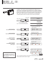
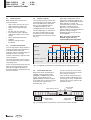
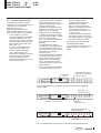
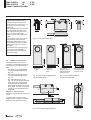
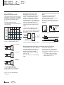
BML-S1B0-Q_ _ _-M_ _ _-_0-KA_ _
BML-S1E0-Q_ _ _-M_ _ _-_0-KA_ _
english
User's Guide
Balluff GmbH
Schurwaldstrasse 9
73765 Neuhausen a.d.F.
Germany
Phone +49 7158 173-0
Fax +49 7158 5010
Servicehotline +49 7158 173-370
[email protected]
www.balluff.com
BML-S1B0-Q_ _ _-M_ _ _-_0-KA_ _
BML-S1E0-Q_ _ _-M_ _ _-_0-KA_ _
Linear Position Encoder
Content
1
Safety Advisories
1
1.1
1.2
1.3
1.4
Safety Advisories .................. 2
Intended use .......................... 2
Qualified personnel ................ 2
Use and testing ...................... 2
Validity .................................... 2
Read this manual before installing
the sensor and placing it in
operation.
2
3
Functional variants ............... 3
Function and
Characteristics ..................... 4
Characteristics ....................... 4
Principle of operation ............. 4
Interface signals ..................... 4
Limit switch function .............. 4
Reference point function ........ 5
The BML displacement sensor is
fitted into a machine or piece of
equipment for its application.
Together with a controller (PLC) it
comprises a displacement
measurement system and may be
used only for this purpose.
3.1
3.2
3.3
3.4
3.5
4
Installing the sensor ............. 6
4.1 Installing sensor and magnetic
tape (linear motion) ................. 6
Distances, tolerances ............. 6
Determining orientation .......... 7
Attaching sensor head ........... 7
Selecting the tape .................. 7
Installing limit switches .......... 8
4.2 Installing sensor and magnet
ring (rotary motion) ................. 8
5
Wiring .................................... 9
5.1 Cable assignments ................. 9
5.2 Connecting the Sense line ..... 9
5.3 Interfaces ............................. 10
6
Selecting the Appropriate BML
and Controller System ......... 11
6.1 Standard BML ...................... 11
6.2 BML with predefined
traverse speed ...................... 11
6.3 BML system with magnet ring .... 12
7
7.1
7.2
7.3
7.4
7.5
8
8.1
8.2
9
10
11
12
Startup ................................. 14
Checking connections ......... 14
Turning on the system .......... 14
Checking system function .... 14
Regular checking ................. 14
Malfunction .......................... 14
Accessories ........................ 14
Limit switch magnets ........... 14
Cover strip ............................ 14
Troubleshooting .................. 15
Technical Data .................... 16
Scope of Delivery ............... 17
Versions (indicated on
part label) ............................ 18
1.1
Intended use
Unauthorized modifications and
non-allowed use will result in loss of
guarantee and warranty.
1.2
Qualified personnel
This manual is intended for
technical personnel who are
involved in installation and setup.
1.3
Validity
This Guide is valid for displacement
sensors models
BML-S1B0-Q-...-KA_ _ and
BML-S1E0-Q-...-KA_ _
An overview of the various versions
can be found in section 12 "Versions" (refer to part label).
Prevailing safety regulations and
codes must be observed for using
the displacement sensor.
The CE Mark verifies
that our products meet
the requirements of
EC Directive
89/336/EEC (EMC Directive)
and the EMC Law. Testing in our
EMC Laboratory, which is
accredited by DATech for Testing
Electromagnetic Compatibility, has
confirmed that Balluff products
meet the EMC requirements of the
following Generic Standards:
EN 61000-6-2 (noise immunity)
english
1.4
Use and testing
EN 61000-6-4 (emission)
2
In particular, measures must be
taken to ensure that a defect in the
displacement sensor will not result
in hazards to persons or equipment.
This includes installation of additional safety limit switches, emergency
stop switches, and the maintaining
of permissible ambient conditions.
BML displacement sensors may not
be used in life-saving systems, in
aircraft, etc.
Emission tests:
RF Emission
EN 55011 Group 1, Class A+B
Noise immunity tests:
Static electricity (ESD)
EN 61000-4-2
Severity level 3
Electromagnetic fields (RFI)
EN 61000-4-3
Severity level 3
Fast transients (Burst)
EN 61000-4-4
Severity level 3
Surge
EN 61000-4-5
Severity level 2
Line-induced noise induced by
high-frequency fields
EN 61000-4-6
Severity level 3
Magnetic fields
EN 61000-4-8
Severity level 4
BML-S1B0-Q_ _ _-M_ _ _-_0-KA_ _
BML-S1E0-Q_ _ _-M_ _ _-_0-KA_ _
Linear Position Encoder
2
Functional variants of the displacement sensor
The BML is a non-contact, incremental displacement feedback system
consisting of a sensor head and a magnetic tape. The system is available in
several variants: with position signal function only, with additional reference
point function and/or with limit switch function. All functions are implemented
by means of magnetic sensing. The reference position is integrated in the
tape, and limit switch magnets can be attached at any desired position.
The following table show the functional variants with their possibilities.
Limit switch sensors
Incremental
sensors
Output signal
A-Signal
B-Signal
Reference signal
none
Single signal
Pole-periodic
Fixed periodic
Reference point sensor
Fig. 2-1: Sensor head configuration
Limit switch
Front and rear
Tape with alternating north
and south poles
System variant 1:
No reference point signal
BML-M0_...-R0000
BML-S1B1...M_0_
Tape with one ref. point
System variant 2:
One reference point signal
BML-M0_...-Rxxxx
BML-S1B1...M_1_
System variant 3:
Pole-periodic reference
point signals
BML-M0_...-R0000
BML-S1B1...M_2_
Tape with multiple ref. points at
equal distances
System variant 4:
Fixed periodic reference
point signals
BML-M0_...-Cxxxx
BML-S1B1...M_1_
Fig. 2-2: Length measurement systems
Note:
For a detailed technical description
and installation instructions for
tapes, see User's Guide for tape at
www.balluff.de
Limit switch magnet
Fig. 2-3: Length measurement system with limit switch sensors, tape with
reference points and limit switch magnets
english
3
BML-S1B0-Q_ _ _-M_ _ _-_0-KA_ _
BML-S1E0-Q_ _ _-M_ _ _-_0-KA_ _
Linear Position Encoder
3
Function and Characteristics
3.1
Characteristics
BML displacement sensors are
characterized by:
– High system accuracy of 50 µm
– High resolution of up to 5 µm
– High traverse speed of up to
20 m/s
– Position signal in real-time
– Insensitive to shock, vibration,
and contamination such as dust
and oil
– Wear- and maintenance-free
– Rugged
– Enclosure rating IP 67 per
IEC 60529
3.2
Principle of operation
The sensing head is attached to the
machine member whose position is
to be determined, while the
magnetic tape is mounted along the
direction of travel. The tape
contains alternating magnetic northand south poles.
The two incremental sensors in the
sensing head measure the magnetic
alternating field.
As the sensing head travels over the
tape the two incremental sensors
pick up the magnetic periods so
that the controller can determine the
distance traveled.
3.3
Interface signals
The sensing head can convert the
sinusoidal and cosinusoidal signals
either into A/B pulses and send
them to the controller (RS422).
The digital A/B pulses are
interpolated in the sensing head.
The two digital pulses A and B are
90° phase-shifted, with the sign
of the phase shift determined by
the direction of travel of the sensor
(Fig. 3-1).
Each edge change from A or B
represents a counting step for the
period counter (UP/DOWN counter).
When Signal A is ahead, the
counting state increases, and when
Signal B is ahead the count
decreases. The controller thus
always knows the increment-precise
position without having to
periodically poll the sensor (realtime capability).
Note, for correct function the
A and B signals must be
evaluated direction-dependent.
Signal A
Signal B
Increment
Forwards
Direction of motion
Backwards
Counter state
Fig. 3-1: Digitized sinusoidal and cosinusoidal signals with period counter
3.4
Limit switch function
When limit switch functionality is
needed, sensing heads can be
equipped in addition with a limit
switch sensor which senses
opposite pole permanent magnets
at the ends of the measuring range
and sends the signals to the
controller (Fig. 3-2).
Limit switch sensors
Limit switch
magnet rear
The limit switch sensors function
then even if the rest of the sensor
fails (security function).
If the actuation range of the limit
switches needs to be longer than
their length (20 mm), multiple limit
switches of the same type can be
mounted in rows.
Incremental
sensors
Limit switch
magnet front
Fig. 3-2: Displacement measurement system with limit switch function
4
english
BML-S1B0-Q_ _ _-M_ _ _-_0-KA_ _
BML-S1E0-Q_ _ _-M_ _ _-_0-KA_ _
Linear Position Encoder
3
Function and characteristics (cont.)
3.5
Reference point function
The reference position is always
required as the starting point for the
count for each incremental
displacement system.
How the reference position is
determined depends on the sensor
type, the tape and on the controller.
– In the simplest system the
sensing head with the sinusoidal
and cosinusoidal sensors can
count only the magnetic periods.
The tape contains only one track
with magnetic north and south
poles (Fig. 3-3).
In this case the displacement
measuring system does not
know the absolute position.
This is determined by the
controller by adding the counted
increments. First however the
reference position must be
determined by a homing move to
the reference switch.
– A sensing head with an additional reference point sensor can
output a reference point signal as
soon as it reaches the
magnetically encoded reference
point on the second track of the
tape (Fig. 3-4). An external
reference switch is not needed.
– In another sensing head version
a reference point signal is output
with each magnetic pole
(Fig. 3-3). The signal is repeated
every 5 millimeters (poleperiodic).
The tape does not require a
second track with a magnetically
encoded reference point. In this
case a reference switch needs to
be used for the selected
reference signal.
The controller precisely evaluates
the reference position when the
switch and the reference point
signal of the sensing head are
active. Therefore the accuracy
requirement for this switch is not
especially great.
– The sensor head with an additional reference point sensor can
also be combined with a
magnetic tape having fixed
periodic reference points
(Fig. 3-4). Here the reference
points are integrated across the
entire length of the tape at
certain constant intervals, such
as every 10 cm.
To determine the exact position,
the reference move must cover
the entire length of the tape up to
the external reference switch.
Advantages of the pole-periodic
and fixed periodic tapes:
You can purchase the tape in long
lengths and trim it yourself to
length.
Incremental
sensors
Tape without reference
point/with pole-periodic
reference point
Fig. 3-3: Displacement measurement system with or without pole-periodic
reference point
Tape with one
reference point
Reference point sensor
Magnetic
reference point
Tape with fixed periodic
referenced points
Magnetic reference points
Fig. 3-4: Displacement measurement system with reference point function
english
5
BML-S1B0-Q_ _ _-M_ _ _-_0-KA_ _
BML-S1E0-Q_ _ _-M_ _ _-_0-KA_ _
Linear Position Encoder
4
Installing the Sensor
Important installation notes:
The permissible distance and
angle tolerances as per Figs. 4-2,
4-3 and 4-4 must be strictly
observed.
The sensing head may not come
in contact with the tape at any
point along the travel. Contact
must still be avoided if the
stainless steel cover (optional) is
used.
The magnetic tape must not be
subjected to strong external
magnetic fields. Direct contact
with holding solenoids or other
permanent magnets must be
avoided.
The displacement measurement
system must be installed in
accordance with the specified
enclosure rating.
4.1
Fig. 4-1: Dimensional drawing
Distances, tolerances
The following distances and
tolerance must be observed when
installing the sensing head and
tape:
– The distance (air gap) between
sensing head and tape as per
Fig. 4-2
– The horizontal offset between
sensing head and tape as per
Fig. 4-3
– The angle tolerances as per
Fig. 4-4. Any tilt along the longitudinal axis of the sensing head
must still maintain the nominal
distance to the tape in the center
of the head. The two incremental
sensors are located there on the
underside.
Magnetic
tape
Stainless
steel cover
strip
Fig. 4-2: Permissible air gap between
sensor head and tape
BML without
reference point or
with pole-periodic
reference point
BML with single
or fixed-periodic
reference point
Fig. 4-3: Permissible horizontal
tolerance to right or left
Note: Even slight tolerance
deviations can affect the measuring
result.
The specified system accuracy
applies only if the tape is installed
parallel to the direction of travel.
Fig. 4-4: Permissible angle tolerances
6
english
Magnetic
tape
BML-S1B0-Q_ _ _-M_ _ _-_0-KA_ _
BML-S1E0-Q_ _ _-M_ _ _-_0-KA_ _
Linear Position Encoder
4
4.2
Installing the Sensor (cont.)
Determining orientation
4.3
The sensor head should be secured
with M3 screws, with its right or left
side against the machine part
whose position is to be determined.
Important!
No forces allowed on the housing
cable. Provide strain relief for the
cable.
Left side
Recommendation for selecting
the tape
BML-S1B: Tape BML-M02-I45
System accuracy ±10 µm
BML-S1E: Tape BML-M02-I46
or magnet rings
Note:
For a detailed technical description
and installation instructions for
tapes, see User's Guide for tape at
www.balluff.de
Front
Rear
The alignments at the front, rear and
left are referred to in the installation
description and are essential for the
correct installation of the sensing
head and tape. Starting from the
travel direction of the sensing
head the orientations are defined in
Fig. 4-5.
Attaching sensor head
Direction of
travel
Right side
Reference point
Fig. 4-5: Orientation
Right side
Limit switch magnet rear
4.5
Limit switch magnet front
Installing limit switches
The front and rear limit switch
magnets must always be installed
on the right side of the sensing
head.
When the limit switch is in a
housing always attach the front
magnet with its nose facing back
and the rear magnet with its nose
facing front.
Limit switch magnet rear:
Slot left of center
Fig. 4-6: Installing the limit switch magnets
When the limit switch is not in a
housing, attach the rear magnet
with the slot to the left of center and
the rear magnet with the slot right of
center (Fig. 4-6, 4-8).
The following applies to both limit
switch types: If the E-stop travel
exceeds the length of the limit
switch magnet, multiple magnets
may be installed in a row (Fig. 4-7).
For ordering information see
Section 7.1.
The limit switch sensor becomes
active as soon as it begins to enter
the magnetic field of the limit switch
magnet (Fig. 4-8).
Limit switch magnet
front: groove right of center
The limit switch sensor is activated at about this position
Emerg. stop travel
Travel direction (measuring range)
Emerg. stop travel
Fig. 4-7: Traverse and emergency stop distances for limit switches with and
without housing
Sensor head
Limit switch adhered to the machine
Maintain distance from mounting surface
Magnetic
tape
Fig. 4-8: Installation example for limit switch without housing
english
7
BML-S1B0-Q_ _ _-M_ _ _-_0-KA_ _
BML-S1E0-Q_ _ _-M_ _ _-_0-KA_ _
Linear Position Encoder
4
4.2
Installing the Sensor (cont.)
Installing sensor and magnet rings (rotary motion)
Important installation notes:
The permissible distance and angle
tolerances as per Figs. 3-5, 3-6 and
3-7 must be strictly observed.
The sensor head must not be
allowed to touch the magnet ring.
The magnetic tape must not be
subjected to strong external
magnetic fields.
Direct contact with holding
solenoids or other permanent
magnets must be avoided.
The displacement measurement
system must be installed in
accordance with the specified
enclosure rating.
Rear view
with cable
The sensor can be installed with the
cable entry to the right or left with
respect to the magnet ring (Fig. 410).
Note:
For a detailed technical description
and installation instructions for
magnet rings, see User's Guide at
www.balluff.de
Front view
Incremental
sensors
Fig. 4-9: Permissible gap
8
english
Fig. 4-10: Permissible r axial offset
Fig. 4-11: Permissible tangential offset
BML-S1B0-Q_ _ _-M_ _ _-_0-KA_ _
BML-S1E0-Q_ _ _-M_ _ _-_0-KA_ _
Linear Position Encoder
5
Wiring
Note the following when making
electrical connections:
The system and the control
cabinet must be at the
same ground potential.
To ensure EMC, which Balluff
confirms with the CE Marking, the
following instructions must be
followed.
5.1
Cable assignments
12-conductor cable with Sense line
(measurement line) for preventing
voltage drop in the incoming line.
Cable
WH
BN
GN
YE
GY
PK
BU
RD
BK
VT
GYPK
RDBU
TR
BK**
white
brown
green
yellow
gray
pink
blue
red
black
violet
gray/pink
red/blue
transp.
black
Signal
A***
/A or n.c.*
B***
/B or n.c.*
Z (Ref. signal)
/Z or n.c.*
GND***
+5 V or 24 V***
GND Sense
+5/24 V Sense
Front limit switch
Rear limit switch
Shield 0.34 mm2
Shield 0.34 mm2
The cable shield must be
grounded on the controller side,
i.e., connect to the protection
ground.
When routing the cable between
the transducer, controller and
power supply avoid proximity to
high-voltage lines due to noise
coupling.
Especially critical are stray
coupling caused by AC harmonics
(e.g., from phase controls), against
which the cable shield offers little
protection.
5.2
Cable length max. 20 m;
conductor cross-section min.
0.14 mm2, max. 0.5 mm2. Longer
cables may be used if their
construction, shielding and routing
resist external noise fields.
Important:
In spite of a voltage drop in the line
a nominal operating voltage of
10 to 30 V or 5 V ±5% must be
ensured (see 5.2).
Connecting the Sense line
To avoid voltage drop in the cable,
when operating at 5 V a controlled
mains adapter with polarity sensing
input should be used (Fig. 5-1). If that
is not possible or desired, the Sense
lines in the 12-conductor cable
should be connected parallel to the
+5 V and GND line (Fig. 5-2).
When operating at 10...30 V it must
only be ensured that the voltage
does not fall below 10 V. Such a
power supply does not normally
possess a Sense line.
Power
supply
Fig. 5-1: 5 V Power supply with
Sense line
Power
supply
Fig. 5-2: 5 V Power supply without
Sense line
* Applies only to BML-S1B0-Q53 and
BML-S1E0-Q53. ** Discontinued
version.
*** These wires only for
BML-S1B0-Q53_-M400 and
BML-S1E0-Q53_-M400.
Calculating the voltage drop in the line
Sample calculation
For the 5 V version of the BML the supply voltage must be 5 V ±5%. The
power supply must ensure this voltage and also compensate for the voltage
drop in the line. When operating at 10...30 V the voltage must be >10 V.
Under the following conditions:
cable length 5 m
Reference pulse is evaluated
Control input impedance = 120 Ω
Use the following formula to calculate the voltage drop in the line:
Vline =
Rl x l x [n x 3.1/Rst + 0.03] where:
Vline
Rl
l
n
Rst
=
=
=
=
Voltage drop in the line in Volt
0.23 for the parallel wiring of the Sense lines with the supply lines (Fig. 5-2)
Cable length in m
3, if the reference pulse is processed in the controller
2, if the reference pulse is not processed in the controller
= Input impedance of the controller in Ohm
Resulting voltage drop is:
Vline = 0.23 x 5 x [3 x 3.1/120 + 0.03] = 0.1 V
english
9
BML-S1B0-Q_ _ _-M_ _ _-_0-KA_ _
BML-S1E0-Q_ _ _-M_ _ _-_0-KA_ _
Linear Position Encoder
5
5.3
Wiring (cont.)
Circuit for reference position
Interfaces
Digital incremental system
The sensor transmits the measured
variable to the controller as a digital
differential voltage signal (RS422) or
as an operating voltage signal
(HTL).
The edge separation A/B
corresponds to the resolution of the
sensing head.
Signal period 360° el.
Depending on the model, the
sensor sends either no reference
signal, a single reference signal
which is magnetically encoded in
the tape, or a periodic reference
signal (period = 5 mm, width of the
reference signal = edge separation,
Fig. 5-3). In the latter case an
external reference switch must be
attached to the desired reference
signal.
Circuit for limit switches front and
back
The opposite poled permanent
magnets at the ends of the
measuring range are each sensed
by a limit switch sensor.
The sensor has a normally closed
function, so that cable break can be
detected.
Controller
Limit switch
front
Rear limit
switch
The accuracy requirements of this
switch are not especially high.
Note: The reference signals from the
limit switch area are not allowed to
be processed.
Fig. 5-6: Limit switch circuit
Edge separation
Reference pulse
Reference
signal for
the
controller
el.
Rear limit switch
External switch
Front limit switch
Fig. 5-3: Digital output signals
Fig. 5-5: Reference position circuit
Fig. 5-7: Limit switch signals
A-channel
Relationship between mechanical resolution and max. frequency
B-channel
The requirements for your controller
(counting frequency) and for the
traverse speed of your system can
be determined from the BML
model used (see part numbering
code, p. 18).
Note the values from the following
table.
Reference
channel
* only for BML S1B0-Q61...
** only for BML S1B0-Q51...
The 24 V inputs are connected to
digital inputs on the controller.
Fig. 5-4: Circuit for following
electronics
10
english
Example for table line 1:
Using a BML with a resolution of
5 µm and a max. speed around
1 m/s ("slow" model) the results are
as follows:
- The smallest edge separation
which your controller must be
able to count is 3.1 µs.
BML-S1B0-Q_ _ _-M_ _ _-_0-KA_ _
BML-S1E0-Q_ _ _-M_ _ _-_0-KA_ _
Linear Position Encoder
6
Selecting the Appropriate BML and Controller System
Tables 6 -1 and 6 -2 show the
relationship between the mech.
resolution, the min. edge separation
and the max. traverse speed for
BML systems using a magnetic
tape.
Important!
The controller/display must be able
to count the minimum time-based
edge separations shown in the
tables (note the counting frequency
of your controller). The min. edge
separation may even be present in
the stopped state due to the internal
interpolation procedure.
6.1
Standard BML (Tab. 6-1)
Determining the appropriate BML
system for an existing controller
(linear motion)
Example (see Table 6-1)
Assumptions:
– Your controller can detect a min.
edge separation of 1.8 µs. If
there is no BML with this min.
edge separation, select a BML
with greater edge separation.
– The max. traverse speed of the
system should be 2 m/s.
Determining the appropriate BML:
– You need a BML with min. edge
separation 2 µs (H-type).
– To be able to traverse at max.
2 m/s, select the model with
10 µm resolution (G-type).
6.2
With the standard BML the maximum traverse speed depends on the edge
separation and on the resolution (see Table 6-1).
In the table the X indicates the min. edge separation in time of the BML
model and Y the mechanical resolution (see part numbering code).
BML - S1A1 - Q61Y - M313 - X0 - KA05 (model example)
Edge separation
Mechanical resolution
Standard BML
F = 5 µm
Resolution Y:
G = 10 µm
H = 25 µm
K = 50 µm
Edge sep. X
Vmax corresponding to edge separation and resolution
D = 0.12 µs
20 m/s
20 m/s
20 m/s
20 m/s
E = 0,29 µs
10 m/s
20 m/s
20 m/s
20 m/s
F = 0,48 µs
5 m/s
10 m/s
20 m/s
20 m/s
G = 1 µs
3.25 m/s
6.5 m/s
14.75 m/s
14.75 m/s
H = 2 µs
1.5 m/s
3 m/s
7.7 m/s
7.7 m/s
K = 4 µs
0.75 m/s
1.5 m/s
3.95 m/s
3.95 m/s
L = 8 µs
0.375 m/s
0.75 m/s
1.7 m/s
1.7 m/s
N = 16 µs
0.195 m/s
0.395 m/s
0.95 m/s
0.95 m/s
P = 24 µs
0.13 m/s
0.26 m/s
0.65 m/s
0.65 m/s
Table 6-1: Standard BML with defined min. edge separations
Determining the appropriate controller for an existing BML system (linear motion)
What does the max. counting frequency of the controller need to be? The
period of the input signal is 4x the edge separation (see Fig. 5-3).
The max. frequency of the input signal is then 1/(4× edge separation).
Example: With an edge separation of 1 µs for the model G BML, the max.
frequency of the input signal is 1/4 µs = 250 kHz. The max. counting
frequency for 4x evaluation is 1/edge separation = 1/1 µs = 1 MHz.
BML with predefined traverse speed (predecessor to the standard BML) Linear motion
The requirements for your controller
(counting frequency) and for the
traverse speed of your system can
be determined from the BML model
used (see part numbering code).
Note the values from following table
6-2.
Example (see Table 6-2, column 2):
For a BML model with 5 µm
resolution (F-type) and a max.
speed of 1 m/s (type code 1) the
following apply:
- The smallest edge separation
which your controller must be
able to count is 3.1 µs.
In the table X indicates the max. traverse speed for the BML model and Y the
mechanical resolution.
BML - S1A1 - Q61Y - M313 - X0 - KA05 (model example)
max. traverse speed (code 1 or 2)
mech. resolution (For code see Tab. 6-2)
Predecessor
BML
F = 5 µm
Vmax X
Resolution Y:
G = 10 µm
H = 25 µm
K = 50 µm
min. possible edge separation
1 = 1 m/s
3.1 µs
6 µs
15.8 µs
15.8 µs
2 = 10 m/s
0.29 µs
0.58 µs
1.56 µs
1.56 µs
Table 6-2: Predecessor BML with defined max. traverse speeds
english
11
BML-S1B0-Q_ _ _-M_ _ _-_0-KA_ _
BML-S1E0-Q_ _ _-M_ _ _-_0-KA_ _
Linear Position Encoder
6
6.3
Selecting the Appropriate BML and Controller System
Determining resolution and max. rotational speed for BML systems with magnet ring (rotary motion)
Step 1
Magnet ring type
First decide how many pulses per
revolution your application requires.
This will be used to select the
magnet ring outside diameter,
the resolution of the sensor head,
and the sensor head model
(BML-S1B..., -S1E...).
Table 6-3 shows for each magnet
ring the relationship between the
number of pulses per revolution and
the resolution of the sensor head.
BML-M2...048/...
BML-M2...072/...
20
32
46
No. of poles
Resolution Y
Sensor head
Pulses per revolution
with 4x interpolation
F = 5 µm
20,000
32,000
46,000
G = 10 µm
10,000
16,000
23,000
H = 25 µm
4,000
6,400
9,200
K = 50 µm
2,000
3,200
4,600
Example (see Table 6-3):
– The application requires 10,000
pulses/revolution.
– These pulses are provided by the
BML system, consisting of a
sensor head with a resolution of
10 µm (G-type) and a BML.M2x...031 magnet ring.
Table 6-3: Pulses/revolution of a BML-S1B... /-S1C... system with magnet
rings.
Step 2A (rotational speed is given)
Step 2B (controller is given)
If the rotational speed is a given
for your application, select
(starting with the magnet ring and
resolution selected in Step 1) the
sensor head with the minimum edge
separation which corresponds to
the specified pulse count/revolution.
If there is a controller with the min.
edge separation, a max. speed
results from a selected resolution
(pulses/revolution).
Example:
Assumptions:
– The specified pulse number is
10.000/revolution (see Step 1:
BML-M2x...031 ring and BML
resolution 10 µm).
– The max. rotational speed should
be 5.000 rpm.
Determining the suitable BML
sensor head (see Table 6-4)
– Search column
"G = 10 µm, 10,000 pulses" for
every line whose rotational speed
is greater than the required
speed.
The sensor head with 0.48 µm
edge separation (F-type) is
suitable.
Together with magnet ring
BML-M2x...031 it meets the
system requirements.
12
BML-M2...031/...
english
Tables 6 -4 to 6 -6 show the
relationship between the min. edge
separation, mechanical resolution
and the max. rotational speed for
BML systems using magnet rings.
Example:
Example
Assumptions:
– Let the min. edge separation be
0.9 µs.
Determining the suitable BML
system (see Table 6-4)
– The edge separation is provided
by the BML system consisting of
a magnet ring BML-M2x...031
and a sensor head with
1 µm edge separation (G-type)
and a resolution of 10 µm
(G-type). Using this system a
max. speed of 3,900 rpm is
possible.
If this speed is not sufficient, the
number of pulses per revolution
(resolution) needs to be reduced,
e.g. to 4000 H-type).
Using this system a max. speed
of 8,850 rpm is possible.
BML-S1E0-Q53H-M413-K0-KA05
mech. resolution Y
(see table for code)
min. edge separation X
(see Tables
6-4 to 6-6 for codes)
BML-S1B0-Q_ _ _-M_ _ _-_0-KA_ _
BML-S1E0-Q_ _ _-M_ _ _-_0-KA_ _
Linear Position Encoder
Table 6-4
mech. resolution Y
F = 5 µm
G = 10 µm
H = 25 µm
K = 50 µm
Pulses/revolution
20,000
10,000
4,000
2,000
min. edge separation X max. kHz A/B-Sig
max. speed for magnet ring BML-M2x...031...
D = 0.12 µs
2,100
12,000
12,000
12,000
12,000
E = 0.29 µs
860
6,000
12,000
12,000
12,000
F = 0.48 µs
520
3,000
6,000
12,000
12,000
G = 1 µs
250
1,950
3,900
8,850
8,850
H = 2 µs
125
900
1,800
4,620
4,620
K = 4 µs
63
450
900
2,370
2,370
L = 8 µs
32
225
450
1,020
1,020
N = 16 µs
16
117
237
570
570
P = 24 µs
10
78
156
390
390
F = 5 µm
G = 10 µm
H = 25 µm
K = 50 µm
32,000
16,000
6,400
3,200
Table 6-5
mech. resolution Y
Pulses/revolution
min. edge separation X max. kHz A/B-Sig
max. speed for magnet ring BML-M2x...048...
D = 0.12 µs
2100
7,500
7,500
7,500
7,500
E = 0.29 µs
860
3,750
7,500
7,500
7,500
F = 0.48 µs
520
1,875
3,750
7,500
7,500
G = 1 µs
250
1,219
2,438
5,531
5,531
H = 2 µs
125
563
1,125
2,888
2,888
K = 4 µs
63
281
563
1,481
1,481
L = 8 µs
32
141
281
638
638
N = 16 µs
16
73
148
356
356
P = 24 µs
10
49
98
244
244
F = 5 µm
G = 10 µm
H = 25 µm
K = 50 µm
46,000
23,000
9,200
4,600
Table 6-6
mech. resolution Y
Pulses/revolution
min. edge separation X max. kHz A/B-Sig
max. speed for magnet ring BML-M2x...072...
D = 0.12 µs
2100
5,217
5,217
5,217
5,217
E = 0.29 µs
860
2,609
5,217
5,217
5,217
F = 0.48 µs
520
1,304
2,609
5,217
5,217
G = 1 µs
250
848
1,696
3,848
3,848
H = 2 µs
125
391
783
2,009
2,009
K = 4 µs
63
196
391
1,030
1,030
L = 8 µs
32
98
196
443
443
N = 16 µs
16
51
103
248
248
P = 24 µs
10
34
68
170
170
english
13
BML-S1B0-Q_ _ _-M_ _ _-_0-KA_ _
BML-S1E0-Q_ _ _-M_ _ _-_0-KA_ _
Linear Position Encoder
7
Startup
8
Accessories (order separately)
7.1
Check connections
8.1
Limit switch magnets
(BML-Z0006)
Caution! The connections are not
protected against polarity reversal
or short circuit! Before turning on
power, check the connections
carefully to prevent components
from being destroyed by incorrect
connections or overvoltage.
7.2
Turn on system
Note that the system may perform
uncontrolled movements when it is
switched on, in particular when it is
switched on for the first time and if
the length measurement system in
part of a control system for which the
parameters have yet to be set.
Therefore be sure that no hazards
could result from an unpredictable
start.
7.3
Regular checking
The functionality of the transducer
system and all its associated
components should be checked
and logged at regular intervals.
7.5
Malfunction
If there is any indication that the
transducer system is not functioning
properly, remove it from service and
secure it against unauthorized use
(see also Troubleshooting).
14
Tape cover
To prevent damage to the tape from
things like chips or chemicals, it
may be covered with a strip of
stainless steel.
Note that the permissible distance
between the sensing head and tape
is reduced now by the thickness of
the cover strip with adhesive film
(0.15 mm) (Fig. 4-2).
Before adhering the cover strip,
thoroughly clean the surface of the
tape (acetone, turpentine, mild
plastic cleaner, no gasoline).
Ship configurations:
1 Tape cover and tape can
be ordered together in the
appropriate length.
2 The tape cover may be
ordered in 4 defined lengths.
Check system function
After installing the transducer
system or replacing the sensing
head, check all functions as follows:
1. Turn on power to the sensor
head.
2. Move the sensing head along the
entire measuring range.
3. Check whether all signals are
output.
4. Check whether the count
direction agrees with the direction
of travel.
If not, reverse connections A and
/A.
7.4
The magnets can be used with or
without housing. The through-holes
make it easy to precisely install
these limit switch magnets
(Fig. 4-8). The housing should be
fitted with a magnet only on its side
facing the sensor.
The space-saving magnets can be
glued or attached using customersupplied holders. The upper side is
marked with a notch.
If the E-stop travel exceeds the
length of the limit switch magnet,
multiple magnets may be installed
in a row (for installation see 4.5).
The scope of delivery includes:
2 magnets with housing
2 magnets without housing, and
1 installation guide
8.2
english
Note:
For a detailed technical description
and installation instructions for
magnet rings, see User's Guide at
www.balluff.de
Fig. 8-1: Magnets and housing
BML-S1B0-Q_ _ _-M_ _ _-_0-KA_ _
BML-S1E0-Q_ _ _-M_ _ _-_0-KA_ _
Linear Position Encoder
9
Troubleshooting
Problem
Possible causes
Remedy/Explanation
The controller is receiving (at times)
no distance information.
The necessary supply voltage is not
present.
Check whether power is present
and whether the BML is properly
connected.
The voltage drop is too great (see
formula page 9).
The system must have an operating
voltage of 10...30 V or 5 ±5%.
Check the voltage on the Sense line
or using the formula (p. 9).
Cables are not connected.
Check cables against the wiring
diagrams.
The orientation of the tape with
reference point is not correct.
The reference point mark must be
on the right side of the sensor head
(Fig. 4-5). Install new tape correctly.
The distance between sensor head
and tape is (in places) wrong.
Adjust the height of the sensor
head. To check, move the head
manually over the entire measuring
range.
The magnetic poles of the tape are
damaged in places by the presence
of strong magnets.
Replace tape.
Position signal is highly noisy
Distance between sensor head and
tape is too great.
Attach sensor head closer to tape
Limit switches not switching
correctly.
The distance between the limit
switch magnets and sensor head is
incorrect.
Check and correct distance and
angle to tape (Fig. 4-6).
The limit switch magnets are
mounted with the wrong side facing
the sensor head (wrong polarity).
Check and correct the limit switch
magnets with respect to the travel
direction (Fig. 4-7).
Reference point signal not being
output.
The orientation of the tape with
reference point is not correct.
The reference point mark must be
on the right side of the sensor head
(Fig. 4-5). Replace tape.
Linearity deviation is out of
tolerance.
The sensor head is not moving parallel to the tape (see Fig. 4-4 for
tolerance).
Distance between sensor head and
tape is too great.
Correctly position the sensor head
(section 4).
The controller is receiving no
distance information at certain
points.
english
15
BML-S1B0-Q_ _ _-M_ _ _-_0-KA_ _
BML-S1E0-Q_ _ _-M_ _ _-_0-KA_ _
Linear Position Encoder
10
Technical Data
Electrical data
Output
Output signal
Reference signal by type
Resolution
Output voltage
Limit switch
Overall system accuracy
Sensor head + tape
(see separate guide for magnetic tape)
Hysteresis depending on air gap
max. non-linearity of the processing
electronics unidirectional
Temperature coefficient of overall
system like steel
Max. traverse speed
Reverse polarity protected
Overvoltage protected
Operating voltage
Current draw
at 5 V operating voltage
Current draw
at 10...30 V operating voltage
Vibration per IEC 60068-2-27 1
Continuous shock
per IEC 60068-2-29 1
Vibration per IEC 60068-2-6 1
Ambient conditions
Operating temperature
Storage temperature
Degree of protection per IEC 60529
Mechanical data
Sensor head to tape gap
Housing material
Connection type
Weight
1
16
Model BML-S1B0-Q
Model BML-S1E0-Q
Digital RS422 or level same as supply voltage (HTL)
A-Signal, B-Signal, reference signal
No signal, one signal, pole-periodic signal, fixed periodic signal
5 µm, 10 µm, 25 µm, 50 µm
Differential RS422 signal or same as supply voltage (HTL)
GND switching (cable break mon.)
Vmax = 28 V, Imax = 20 mA, N.C.,
±50 µm up to 1 mm distance,
±70...100 µm depending on
above that ±60 µm with tape
distance with tape BML-M01-I46
BML-M01-I45
3 to 7 µm
±30 µm at tape distance <1 mm
±50 µm at distance <2 mm
±40 µm at tape distance >1 mm
to tape
10.5 x 10⁻⁶ K-1
Depending on model, see Table 6-1, 6-2
Yes, at 10...30 V
no
5 V ±5% or 10...30 V
< 50 mA + current draw of the controller (depending on internal resistance)
< 40 mA + current draw of the controller (depending on internal resistance)
100 g/6 ms
100 g/2 ms
12 g, 10...2000 Hz
–20 °C...80 °C
–30 °C...85 °C
IP67
0.01...2 mm
PBT
12-conductor cable (LIf12YFCF11Y 6×2×0.08 mm2)
11 g without cable
Individually determined as per Balluff Factory Standard
english
BML-S1B0-Q_ _ _-M_ _ _-_0-KA_ _
BML-S1E0-Q_ _ _-M_ _ _-_0-KA_ _
Linear Position Encoder
10
Technical Data (cont.)
Limit switch magnet BML-Z0006
Dimensions L x W x H
Magnet housing
Limit switch magnet
Cable
Type
Operating temperature
Flexed
Fixed
Cable diameter
Cable bending radius
Flexed
Fixed
11
20 x 12 x 9.5 mm
20 x 2 x 5 mm
Scope of delivery
Sensor head
Short guide
2 limit switch magnets
(only for BML ...M_ _3...)
PU cable:12-conductor, drag chain
compatible
–20...80 °C
–40...90 °C
5.4 +0.2 mm
81 mm
41 mm
english
17
BML-S1B0-Q_ _ _-M_ _ _-_0-KA_ _
BML-S1E0-Q_ _ _-M_ _ _-_0-KA_ _
Linear Position Encoder
11
Versions
Part numbering for sensing head (printed on part label)
BML - S1 B 0 - Q 5 3 G - M 4 1 3 -1 0 - KA05
(example)
min. edge separation/max. traverse speed:
D = 0.12 µs
E = 0.29 µs
F = 0.48 µs
G = 1 µs
H = 2 µs
K = 4 µs
L = 8 µs
N = 16 µs
P = 24 µs
1 = approx. 1 m/s (discontinued model, cannot be ordered)
2 = approx. 10 m/s (discontinued model, cannot be ordered)
Limit switch
0 = no limit switch
3 = two limit switches
Reference signal
0 = no signal
1 = single signal or fixed periodic
2 = pole-periodic signal
Pole width
4 = 5 mm
Resolution (edge separation A/B)
F = 5 µm
G = 10 µm
H = 25 µm
K = 50 µm
Output voltage
1 = digital square wave signal RS422
3 = level same as supply voltage (only for 10...30 V)
Supply voltage
5 = 24 V (10...30 V)
6=5V
Style
B = Non-linearity of the electronics ±50...±60 µm
E = Non-linearity of the electronics ±100 µm
18
english
No. 841 971-726 E • 02.108392 • Edition 0711; specifications subject to changes. • Replaces edition 0512
Connection:
KA05 = PUR cable 5 m
Possible cable lengths: 2, 5, 10, 15, 20 m