1
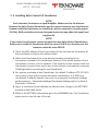
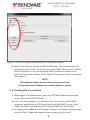
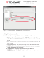
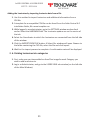
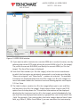
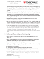
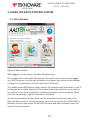
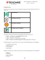
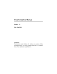
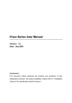
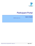
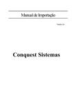
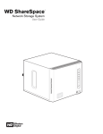
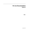
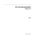
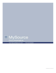
USER GUIDE
Table of Contents
1. OVERVIEW3
1. 1. Basic concepts3
2. INSTALLING AALTO CONTROL SYSTEM
4
2. 1. Installing Aalto Control 4.0 software:
5
2. 2. Creating user names for Aalto Control software:
5
2. 3. Installing Aalto Control 4.0 Coordinator
7
2. 4. Creating data tree structure
8
2. 5. Adding luminaires
9
2. 6. Dividing luminaires into categories
11
2. 7. Setting up Software settings and Email reporting
13
3. USING THE AALTO CONTROL SYSTEM
14
3. 1. Main Window
14
3. 2. User view
15
3. 3. Reports view
17
AALTO CONTROL 4.0 USER GUIDE
VOT 72 - 25.2.2014
1. OVERVIEW
Aalto Control 4.0 is a system used for controlling and managing Teknoware Aalto
Control compatible emergency and exit luminaires. Aalto Control allows the user to:
•
•
•
•
•
•
•
arrange luminaires by groups such as floors and other areas, buildings and sites
define the type of luminaires used
observe the luminaire’s state and conditions
gather information and logs of errors and executed tests
receive automatic status reports via email
turn luminaires to ON, OFF or BLINK state
set prohibition time schedules for luminaire tests
Aalto Control delivery consists of one or more Wireless/Ethernet Aalto Coordinator
unit(s), the Aalto Control software on a USB memory drive, and a USB licence dongle.
1. 1. Basic concepts
Aalto Coordinator – an Ethernet-based network device used for communicating
between the Aalto Control software and the Aalto Control self-contained luminaires.
Emergency luminaire – a non-maintained luminaire meant for maintaining a required
level of illumination during an emergency (such as a power failure).
Exit luminaire – a maintained luminaire meant for illuminating exit signs during an
emergency (such as a power failure) as well as normal operation.
Categories – Sites, Buildings and Areas (see below). In addition to being used as levels
in the data tree, the categories can also be used for targeting actions to defined groups
of luminaires. For example, you can turn ON all the luminaires under a specific Area.
Site – The topmost category in the Aalto Control 4.0 software data tree. A site can
contain several Buildings. A site image can be set for each Site.
Building – A category in the Aalto Control 4.0 software data tree, representing an
entire building. A Building can contain several Areas. A building image can be set for
each Building.
Area – A category in the Aalto Control 4.0 software data tree representing a certain
area of a building, such as a single floor. An area image, such as a layout plan, can be
set for each Area.
3
AALTO CONTROL 4.0 USER GUIDE
VOT 72 - 25.2.2014
CSV file –A plain text file containing tabular luminaire data that can be imported
directly to the Aalto Control system.
RF identifier – A unique RF ID code that identifies each individual luminaire.
PAN ID – A network channel identifier used in Wireless Aalto devices. PAN ID can
be used for locking a group of Aalto luminaires to communicate with only a defined
Wireless/Ethernet Aalto Coordinator unit. This is useful if there are several Aalto
Coordinator units (or other wireless devices using the same protocol) on the area
2. INSTALLING AALTO CONTROL SYSTEM
Process description:
1. Install the Aalto Control 4.0 software.
2.Create the user names.
3.Install the Aalto Coordinator(s), and set up the Coordinator settings in the
software.
4.Create structure (Sites, Buildings, Areas).
5.Add luminaires to the system.
6.Divide the luminaires into selected sections of the structure.
Requirements:
Aalto Control 4.0 is compatible with Windows XP and Windows 7 32/64 operating
systems. Please note that while the system originally requires only a few megabytes
of hard drive space for installation, the actual required drive space depends on the
amount of luminaires, images and amount of logs. It is recommended that at least a
few hundred megabytes of hard drive space is reserved for the Aalto Control software.
Make sure to check occasionally that enough free space is available.
The HELP button opens this user’s guide in a PDF format. For this, a PDF reader
software is required. The Email reporting system requires an internet connection.
4
AALTO CONTROL 4.0 USER GUIDE
VOT 72 - 25.2.2014
2. 1. Installing Aalto Control 4.0 software:
1. Log in as Administrator.
2.Disable all rest and power saving modes before installing Aalto Control.
3.Connect the Aalto Control USB drive to a USB port and open the USB drive root
folder.
NOTE!
Make sure the USB dongle is not connected at this point.
4.Run the installation wizard (Aalto4.exe). The program will guide you through
the installation process. If you have a firewall in use, allow the network
communication of the Aalto system.
5.After the installation is completed, connect the USB dongle before starting up
the program.
6.If at some point you want to make a backup copy of the Aalto database alone,
you can simply copy the AaltoDB.db -file from the installation folder.
2. 2. Creating user names for Aalto Control software:
1. Log in to your computer as Administrator. Start the Aalto 4 software. Log in to
Aalto 4 as administrator.
NOTE!
When starting up the software for the first time, you must enter a new password for
the user “Administrator”. To do this, simply select a new password, and log in with
it. Make sure you remember the password! The system will automatically save the
selected password for “Administrator”.
2.Go to SETTINGS sub window by clicking the SETTINGS icon on the right side of
the Main window (see image below).
5
AALTO CONTROL 4.0 USER GUIDE
VOT 72 - 25.2.2014
Figure 1. Main Window: SETTINGS
3.While in the SETTINGS window, go to USER tab. To add users to the system,
click the NEW USER button. ADD NEW USER window will open. Enter the user
name and password, an optional note about the user, and select the user level.
The user levels are:
• Basic user can use USER VIEWS window, including area images and luminaire
states.
• Medium user can also use the REPORTS window, and set luminaire states,
print out reports, set up luminaire test schedules, and set up luminaires on
floor maps.
• Admin user has unlimited rights to the system. This access level is used for
e.g. setting up the system.
NOTE!
Make sure your administrator password is not lost.
If the password is lost, contact Teknoware’s After Sales.
4.When closing the Aalto Control 4.0 software, first log out, then close the
software normally. After this, the Aalto Control process will remain running. To
start the software again, double-click the Aalto Control icon from the system
tray (next to the clock and date in Windows taskbar). To close the software,
right-click the icon and select Exit.
6
AALTO CONTROL 4.0 USER GUIDE
VOT 72 - 25.2.2014
2. 3. Installing Aalto Control 4.0 Coordinator
NOTE!
Each luminaire functions as a signal amplifier. Make sure that the distance
between the Aalto Control Coordinator and the nearest luminaire and the distances
between individual luminaires are suitable for wireless connection (usually approx.
10-20m). Walls and other structures between luminaires may affect the signal level
significantly.
NOTE!
If your Aalto Control system consists of more than one Aalto Control Coordinators,
make sure to install the Coordinator with the correct PAN ID to a location near the
luminaires with the same PAN ID.
1. Check the MAC address of the Coordinator(s) from the label on the bottom of
the coordinator, and write the address down.
2.Attach the Coordinator(s) to a pre-planned location according to the
instructions included in the Coordinator delivery. If the system consists of one
Coordinator, connect it to the network. If the system consists of more than one
Coordinator, connect them one by one to the network, and make the necessary
IP settings before connecting the next Coordinator.
3.For systems consisting of one Coordinator, the default IP address 172.22.9.210
can be used. If the system consists of several coordinators, or if DHCP or a
non-default IP address needs to be used, see a separate Coordinator Settings
guide located in ...CoordinatorSettings\CoordinatorSettings.pdf in the Aalto 4
installation USB drive.
4.Log in to the Aalto Control software as Administrator, and go to the SETTINGS
window as described earlier.
5.While in the SETTINGS sub window, go to the HARDWARE tab. The Coordinator
options are on the left side of the tab.
7
AALTO CONTROL 4.0 USER GUIDE
VOT 72 - 25.2.2014
Figure 2. SETTINGS window, HARDWARE tab, Coordinator options
6.Add a Coordinator by clicking the ADD NEW button. The system prompts for
Coordinator details. Enter the previously checked MAC address and IP address
of the Coordinator in the corresponding fields, and add an optional note
about the Coordinator. Repeat the procedure if the system consists of multiple
Coordinators.
NOTE!
The Advanced Settings are for authorized personnell only.
Changing Advanced Settings may seriously affect the system.
2. 4. Creating data tree structure
1. While logged in as Administrator, go to the SETTINGS window as described
earlier. Select the STRUCTURE tab.
2.SITE is the main category, so create them first. Then create the BUILDING
categories, and define the SITES under which the BUILDINGS are set. Lastly,
create the AREAS, and define both SITE and BUILDING for each AREA.
3.An image can be added for each category (buttons: Site Image, Building Image
and Area Plan). Supported image formats are jpg, png, gif and tiff.
8
AALTO CONTROL 4.0 USER GUIDE
VOT 72 - 25.2.2014
NOTE!
While not mandatory, it is highly recommended that
a layout image is added to each AREA.
4.The images can be removed or updated by clicking the MODIFY button under
each category.
5.The created categories can be removed by clicking the REMOVE button under
each category. Removing a root category will remove all subcategories.
2. 5. Adding luminaires
When adding new luminaires, note that each luminaire has a unique RF identifier (0x
followed by 16 hexadecimal symbols). The RF identifier should always be the primary
method of identifying a luminaire.
In order to divide the luminaires into different AREAs, it is highly recommended that
the categories are created before adding the luminaires.
Adding the luminaires automatically
1. Use this method to automatically search for all available luminaires. The
system can automatically add the RF identifiers for all luminaires. For newer
Teknoware luminaires, such as TWT80 and TWT90, the system can also
automatically add the type and model. Additional information must be added
manually.
2.While logged in as Administrator, go to the SETTINGS window as described
earlier. Select the HARDWARE tab. The Luminaire options are on the centre of
the tab.
3.Select the Coordinator to which the luminaires are connected from the left side
of the window.
4.Click the AUTOMATIC SEARCH button. Wait until the process is finished. A
confirmation note is displayed including the total amount of luminaires and
new added luminaires.
9
AALTO CONTROL 4.0 USER GUIDE
VOT 72 - 25.2.2014
Figure 3. SETTINGS window, HARDWARE tab, Luminaire options
Adding the luminaires manually
Use this method to manually add the luminaires and additional information.
1. While logged in as administrator, go to the SETTINGS window as described
earlier. Select the HARDWARE tab. The Luminaire options are on the centre of
the tab.
2.Select the Coordinator to which the luminaires are connected from the left side
of the window.
3.Click ADD MANUALLY. The system will prompt you for additional information:
• RF ID: The RF ID of an individual luminaire. Note that a laser bar code reader
can be used to insert this information.
• TYPE: Select the type of the luminaire from the drop down list.
• MODEL: An optional field for the luminaire model.
• NOTE 1-4: Four free text fields for additional information about the luminaire.
10
AALTO CONTROL 4.0 USER GUIDE
VOT 72 - 25.2.2014
Adding the luminaires by importing luminaire data from a file
1. Use this method to import luminaires and additional information from a
CSV-file.
2.A template for a compatible CSV-file can be found from the Aalto Control 4.0
installation folder, file name template.csv.
3.While logged in as administrator, go to the SETTINGS window as described
earlier. Select the HARDWARE tab. The Luminaire options are on the centre of
the tab.
4.Select the Coordinator to which the luminaires are connected from the left side
of the window.
5.Click the IMPORT FROM FILE button. A Select file -window will open. Browse to
the folder containing the CVS-file, select the file and click Import.
6.Wait for the import process to complete. A confirmation note will be displayed.
2. 6. Dividing luminaires into categories
1. First, make sure you have added an Area Plan image for each Category you
wish to add luminaires to.
2.Log in as Administrator, and go to the USERS VIEW sub window (on the left side
of the Main Window).
11
AALTO CONTROL 4.0 USER GUIDE
VOT 72 - 25.2.2014
Figure 4. USERS VIEW window
3.If you want to add a luminaire to a certain AREA (as is usually the case), start by
selecting the correct SITE under which the correct AREA is (no. 1 in the image).
The, select the correct BUILDING, and finally the correct AREA (no. 2 in the
image). The Area Plan image is displayed.
4.From the Filters section (no. 3 in the image), select the correct coordinator
to which the luminaires are wirelessly connected to, and make sure that the
“Show not assigned” and “Show faulty” –options are selected. The available
luminaires are displayed below the Area Plan image (no. 4 in the image). For
more information about the luminaire icons and viewing options see chapter
3.2 User View.
5.The Label to show –section (no. 3 in the image) allows you to sort and filter
the luminaires (no. 4 in the image). Simply select a Note –field or the RF-ID
option from the drop down list. The selected information will be displayed
attached to the luminaire icon (no. 4 in the image), sorted alphabetically. You
can also filter the displayed luminaires by typing a filter rule to the Label Filter
–field. For example, if you have written luminaire location data to Note 2 data
field, e.g. Office 1, Office 2 and Office 3, you can now filter the luminaires by
12
AALTO CONTROL 4.0 USER GUIDE
VOT 72 - 25.2.2014
selecting Note 2 from the drop down list, and typing a corresponding filter rule
(for example “Office 2”). A wild card * can also be used, so filter rule “Office*”
would display all luminaires with the Note 2 data starting with the word
“Office”.
6.Choose a luminaire you wish to add to the Area. Identify the luminaire by using
the RF ID (or by other information, if the luminaire has for example unique
Note data). The RF ID of a luminaire can be seen by either leaving the mouse
cursor on a luminaire icon for a while, or by left clicking the luminaire icon and
selecting “View status”.
7.By scrolling and zooming, adjust the Area image in a way that the actual
location of the luminaire is visible.
8.Left click the luminaire icon, and select “Set to map”. Then, from the image, left
click the location of the luminaire. The Luminaire icon is moved to the selected
location. Repeat the procedure until all luminaires are set to the correct Areas.
9.If you want to adjust the luminaire location, click on the Commission mode
(no. 5 in the image), click the luminaire icon you wish to move, and drag it to
the correct place. Pressing Esc or the right mouse button while the luminaire
is selected will restore the luminaire to its original location. While the
Commissioning mode is active, checking the Grid checkbox will display a guide
grid.
2. 7. Setting up Software settings and Email reporting
1. While logged in as Administrator, go to the SETTINGS and select the SOFTWARE-tab.
2.Add 1-5 email addresses to which you want the system to send reports to. To
send a test email report for the set addresses, click the TEST button.
3.Select the options for the email reporting:
• Warnings: includes warnings to the report (for more information see step 4)
• Faults: includes faults to the report
• Reports: send a full report.
• Time interval: defines how often the defined report is sent.
4.Set the Warning level: use this slider to define how many percent of faulty
luminaires generates a Warning to the reports.
5.From the Icon Size –drop down list, you can set up the luminaire icon size for
the User View. From the Alternate names -fields you can change the titles for
Note datafields.
6.Click SAVE to save the settings
13
AALTO CONTROL 4.0 USER GUIDE
VOT 72 - 25.2.2014
3. USING THE AALTO CONTROL SYSTEM
3. 1. Main Window
Figure 5. Main window
After logging in to the system, the Main Window opens.
On the upper part of the Main Window, you can see the user name you are logged
in as (1). To log out, click the Log out button in the upper right corner of the window.
Clicking the ? symbol opens the User Manual in PDF format.
The middle section (2) displays a quick view of the System Status Information. A red X
is displayed on the right side part of this section if warnings and faults are present in
the system. If only faults are present, a yellow exclamation mark is displayed. When
there are no warnings, a green checkmark is displayed.
The three sub windows of the system can be accessed from the lower side of the
Main Window, simply by clicking the icons. Basic users can access the USER VIEWS, a
Medium users can also access the REPORTS window, and Admininistrator users can
access all three windows.
14
AALTO CONTROL 4.0 USER GUIDE
VOT 72 - 25.2.2014
3. 2. User view
Figure 6. User view
(1)
Data tree or Site list (select the view from (2).
(2)
View selection. An option to display only the faulty luminaires. On the right side there is a drop down list from which you can select the informa-
tion field that is displayed as the luminaire identification.
(3)
Image window, in which the category image, e.g. a floor plan (if added) of the selected category is displayed.
(4)
Filters for displaying the luminaires. If these options are checked, unassigned and/or faulty luminaires will be shown below the image window.
NOTE!
To use commission mode or other system set up options,
you need to log in as Admin.
See chapter 2.6 Dividing luminaires into categories for more details
about the Filters and Label to Show –options (4 on the Image).
15
AALTO CONTROL 4.0 USER GUIDE
VOT 72 - 25.2.2014
Luminaire icons
From the luminaire icon you can interpret the type and status of the luminaire. The
icons are:
Exit luminaire
Emergency luminaire
Third party luminaire
Luminaire type not defined
The status of a luminaire can be interpreted by the color of the icon:
• Green – luminaire is switched ON without errors
• Grey – luminaire is switched OFF
• Yellow – luminaire is temporarily unavailable
• Red – luminaire is malfunctioning or has not responded for 24 hours
By left-clicking an icon with the mouse cursor, the following options are displayed:
•
•
•
•
Set / Remove from map
Add/View notes
Go to history
View Status
By right-clicking an icon with the mouse cursor, the following options are displayed:
•
•
•
•
Refresh
BLINK ON
Switch ON/OFF
Run test
16
AALTO CONTROL 4.0 USER GUIDE
VOT 72 - 25.2.2014
NOTE!
Setting a luminaire to OFF or BLINK state should only be done
under appropriate circumstances. Also note, that depenfing on the system size, it
may take a while for the state update to take affect.
3. 3. Reports view
The Reports view contains two different selection tools (1) and (2) and three action
tool sets (4), (5) and (6). The action tool sets only affect the luminaires selected in the
luminaires list (3).
Figure 7. Reports view
(1) Selecting a category
Check a selection box, or boxes from the Selection tree. Selecting a root category will
automatically check all the subcategories. Selecting the highest category will select all
the luminaires.
17
AALTO CONTROL 4.0 USER GUIDE
VOT 72 - 25.2.2014
(2) Filtering the luminaires list
As a default, the system will display all the luminaires within the selected categories.
To filter the luminaire list, use the Filters –tools. Note that you can use a wildcard “*”
in all open text fields.
(3) Luminaires list
The luminaires list can be sorted according to any data field by clicking the header of a
column. If a luminaire on the list is placed on a category image, a Map link is displayed.
Clicking this link will open the USERS VIEW window, and display the correct image
centred to the luminaire in question.
To select a luminaire/luminaires, check the Selection option for all luminaires. To select
all luminaires displayed in the list, click the Select all button in the upper right corner
of the window.
(4) Actions
These buttons only affect the selected luminaires.
From this tool set, you can:
•
•
•
•
•
Set the luminaires to BLINK mode
Switch luminaires ON or OFF
REMOVE luminaires from the system
PRINT a list of luminaires
Update the data fields for luminaires by first writing the updated information to
the Note fields in the Luminaires list (3), and then clicking the SAVE icon. Note
that right-clicking a selected data field will open a drop down list containing all
previously entered data. If you want to add an identical Note –data to several
luminaires, this option will allow you to do so without writing the data to each
field manually.
NOTE!
Setting a luminaire to OFF or BLINK state should only be done
under appropriate circumstances.
(5) History
To use the History tools, first select the luminaires, and then set a time period from
which you want the history information displayed. Finally, select the order in which the
list is displayed (newest/oldest first).
18
AALTO CONTROL 4.0 USER GUIDE
VOT 72 - 25.2.2014
From this tool set, you can:
• PREVIEW the history report with the previously set time limit and selections
• PRINT the selected history report
• EXPORT the history report to a file.
(6) Test prohibition (only for Teknoware TWT80 and TWT90 luminaires)
With the Test prohibition tool you can set up time periods, during which the luminaires
are not allowed to run tests. To add a Test prohibition time limit:
1. Click the ADD TIME button.
2.Set up the time period, and enter an optional GROUP name. Select whether
you want the Prohibition time to affect battery test or all tests. Click the SAVE
button.
3.A Prohibition time period is now created. To apply this Prohibition time, select
luminaire(s) from the Luminaires list, and click APPLY TO SELECTED button. The
selections may be removed with the REMOVE FROM SELECTED button.
4.You can modify the Test prohibition time rule by selecting a Test prohibition
time, and clicking the MODIFY button. To remove a Test prohibition time rule
from the system, select a rule and click the REMOVE button.
NOTE!
Modifying a Test prohibition time WILL affect all the luminaires
using said prohibition time rule!
NOTE!
Carefully plan the Test Prohibitions before implementing them, leaving enough time
for each luminaire to run the automatic tests. It is recommended that no less than
12 hours of “free” time is left for each luminaire. Also note, that overlapping or
large Test Prohibition groups may result in groups of luminaires running tests
simultaneously.
5.You can view or print the all the Test prohibition time rules by clicking the
VIEW/PRINT –button.
19
(7) Alarm relays (for setting up the Aalto Alarm Module TST5107)
With the Alarm relays tab you can set up relay controlled device(s) which will be activated if
a defined luminaire generates an error.
To set up an alarm device to the system, first install the TST5107 module according to
separate Installation Guide delivered with the module. After the device is installed, click the
ADD button.
1. Enter the IP address of the TST5107 module. Enter an optional free description.
Click SAVE. The alarm module is now installed. You can MODIFY it or REMOVE it by
clicking corresponding buttons.
2.Select the correct Alarm device from the list on the left side of the Alarm relays tab.
3.Select a luminaire, or a group of luminaires you wish to assign to this device from
the Luminaires list (3) and click ASSIGN TO SELECTED button.
4.If a luminaire assigned to an alarm device generates an error to the Aalto system,
the relay output Q1 of the alarm module will be closed.
To view the luminaire(s) added to a device, select the device and click VIEW. You can also
print a list of the luminaires from this view.
Clicking the TEST button will start a test, during which the Q1 relay of the selected TST5107
module will open and close repeatedly. This feature can be used for checking that the
connection and the device are functioning correctly. Stop the test by clicking the STOP TEST
button before normal operation.
Contact Information:
Teknoware Oy, Ilmarisentie 8, FI-15200 Lahti,
Tel: +358 (0)3 883 020, Fax: +358 (0)3 8830 260,
Email: [email protected], www.teknoware.fi