1
EPack™ Controller
User Guide
EPack™ Power management and control units
Versions 2.00 and later
HA031414 issue 1
April 2013
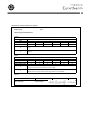
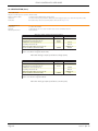
Restriction of Hazardous Substances (RoHS)
Epack
Product group
Table listing restricted substances
Chinese
ℶ❐
Epack
┮䘖㲰⧦⸘⪈
┮䘖㲰⧦⸘⪈
杔
X
X
㒢↪᧚ᢱ৻屗嫷
Ქኂ‛德㒥⏒侯
㻭
柘
⏼ↆ杻
X
O
O
X
O
O
⮩䅃勣啾
O
O
⮩䅃ℛ啾搩
O
O
O
␜年㦘㹡㦘⹂䓸德⦷年捷ↅ㓏㦘⧖德㧟㠨₼䤓⚺摞⧖⦷SJ/T11363-2006 㪖屓⸩䤓棟摞尐
᳞એਅޕ
X
␜年㦘㹡㦘⹂䓸德咂⺠⦷年捷ↅ䤓㩟⧖德㧟㠨₼䤓⚺摞怔⒉SJ/T11363-2006 㪖屓⸩䤓
㒢㊂ⷐ᳞ޕ
English
Product
Epack
Power Module 16-32A
Power Module 40-63A
O
X
Pb
X
X
Restricted Materials Table
Toxic and hazardous substances and elements
Hg
Cd
Cr(VI)
PBB
X
O
O
O
X
O
O
O
PBDE
O
O
Indicates that this toxic or hazardous substance contained in all of the homogeneous materials for
!
"
Indicates that this toxic or hazardous substance contained in at least one of the homogeneous
Approval
Name:
Position:
Martin Greenhalgh
Quality Manager
IA029470U745 Issue 1 Feb 13 (CN29672)
Signature:
Date:
EPACK CONTROLLER: USER GUIDE
EPack Power Controller
User Guide
List of sections
Section
Page
1 Introduction . . . . . . . . . . . . . . . . . . . . . . . . . . . . . . . . . . . . . . . . . . . . . . . . . . . . .
3
2 Installation. . . . . . . . . . . . . . . . . . . . . . . . . . . . . . . . . . . . . . . . . . . . . . . . . . . . . . .
3
3 Operator interface . . . . . . . . . . . . . . . . . . . . . . . . . . . . . . . . . . . . . . . . . . . . . . . . 10
4 Quickstart . . . . . . . . . . . . . . . . . . . . . . . . . . . . . . . . . . . . . . . . . . . . . . . . . . . . . . . 13
5 Configuration from the front panel. . . . . . . . . . . . . . . . . . . . . . . . . . . . . . . . . . 19
6 Configuration using iTools . . . . . . . . . . . . . . . . . . . . . . . . . . . . . . . . . . . . . . . . . 24
7 Using iTools . . . . . . . . . . . . . . . . . . . . . . . . . . . . . . . . . . . . . . . . . . . . . . . . . . . . . 64
8 Parameter addresses. . . . . . . . . . . . . . . . . . . . . . . . . . . . . . . . . . . . . . . . . . . . . . 86
9 Alarms . . . . . . . . . . . . . . . . . . . . . . . . . . . . . . . . . . . . . . . . . . . . . . . . . . . . . . . . . . 87
10 Maintenance. . . . . . . . . . . . . . . . . . . . . . . . . . . . . . . . . . . . . . . . . . . . . . . . . . . . 90
A Technical specification . . . . . . . . . . . . . . . . . . . . . . . . . . . . . . . . . . . . . . . . . . . . 93
Index. . . . . . . . . . . . . . . . . . . . . . . . . . . . . . . . . . . . . . . . . . . . . . . . . . . . . . . . . . . . . .
i
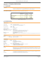
Associated documents
HA028838 Printable version of iTools Help
HA025464 EMC installation guidelines
Software effectivity
This manual refers to instruments fitted with software version 2.0.
HA031414
Issue 1 Apr 13
Page i
EPACK CONTROLLER: USER GUIDE
Epack Controller
User Guide
Contents List
Section
Page
SAFETY NOTES . . . . . . . . . . . . . . . . . . . . . . . . . . . . . . . . . . . . . . . . . . . . . . . . . . . . . . . . . . .
SELV . . . . . . . . . . . . . . . . . . . . . . . . . . . . . . . . . . . . . . . . . . . . . . . . . . . . . . . . . . . . . . . . . . . . .
SYMBOLS USED IN THE INSTRUMENT LABELLING . . . . . . . . . . . . . . . . . . . . . . . . . . . .
1 INTRODUCTION . . . . . . . . . . . . . . . . . . . . . . . . . . . . . . . . . . . . . . . . . . . . . . . . . . . . . . . .
1.1 UNPACKING THE UNITS . . . . . . . . . . . . . . . . . . . . . . . . . . . . . . . . . . . . . . . . . . . . . . .
2 INSTALLATION . . . . . . . . . . . . . . . . . . . . . . . . . . . . . . . . . . . . . . . . . . . . . . . . . . . . . . . . .
2.1 MECHANICAL INSTALLATION . . . . . . . . . . . . . . . . . . . . . . . . . . . . . . . . . . . . . . . . . .
2.1.1 Fixing details . . . . . . . . . . . . . . . . . . . . . . . . . . . . . . . . . . . . . . . . . . . . . . . . . . . . .
2.2 ELECTRICAL INSTALLATION . . . . . . . . . . . . . . . . . . . . . . . . . . . . . . . . . . . . . . . . . . . .
2.2.1 EPack supply voltage . . . . . . . . . . . . . . . . . . . . . . . . . . . . . . . . . . . . . . . . . . . . . .
CONNECTION DETAILS . . . . . . . . . . . . . . . . . . . . . . . . . . . . . . . . . . . . . . . . . . . . .
2.2.2 Load wiring . . . . . . . . . . . . . . . . . . . . . . . . . . . . . . . . . . . . . . . . . . . . . . . . . . . . . .
ENABLE INPUT . . . . . . . . . . . . . . . . . . . . . . . . . . . . . . . . . . . . . . . . . . . . . . . . . . . . .
ALARM ACKNOWLEDGE . . . . . . . . . . . . . . . . . . . . . . . . . . . . . . . . . . . . . . . . . . . .
MAIN SETPOINT . . . . . . . . . . . . . . . . . . . . . . . . . . . . . . . . . . . . . . . . . . . . . . . . . . . .
RELAY OUTPUT . . . . . . . . . . . . . . . . . . . . . . . . . . . . . . . . . . . . . . . . . . . . . . . . . . . .
COMMUNICATIONS PINOUTS . . . . . . . . . . . . . . . . . . . . . . . . . . . . . . . . . . . . . . .
3 OPERATOR INTERFACE . . . . . . . . . . . . . . . . . . . . . . . . . . . . . . . . . . . . . . . . . . . . . . . . .
3.1 DISPLAY . . . . . . . . . . . . . . . . . . . . . . . . . . . . . . . . . . . . . . . . . . . . . . . . . . . . . . . . . . . . . .
3.2 PUSHBUTTONS . . . . . . . . . . . . . . . . . . . . . . . . . . . . . . . . . . . . . . . . . . . . . . . . . . . . . . .
3.2.1 Pushbutton functions . . . . . . . . . . . . . . . . . . . . . . . . . . . . . . . . . . . . . . . . . . . . . .
3.2.2 Menu item value selection . . . . . . . . . . . . . . . . . . . . . . . . . . . . . . . . . . . . . . . . .
3.3 FRONT PANEL EVENT INDICATION . . . . . . . . . . . . . . . . . . . . . . . . . . . . . . . . . . . . .
3.3.1 Instrument events . . . . . . . . . . . . . . . . . . . . . . . . . . . . . . . . . . . . . . . . . . . . . . . . .
3.3.2 Indication alarms . . . . . . . . . . . . . . . . . . . . . . . . . . . . . . . . . . . . . . . . . . . . . . . . .
3.3.3 System alarms . . . . . . . . . . . . . . . . . . . . . . . . . . . . . . . . . . . . . . . . . . . . . . . . . . . .
3.3.4 Process alarms . . . . . . . . . . . . . . . . . . . . . . . . . . . . . . . . . . . . . . . . . . . . . . . . . . .
4 QUICKCODE . . . . . . . . . . . . . . . . . . . . . . . . . . . . . . . . . . . . . . . . . . . . . . . . . . . . . . . . . .
4.1 QUICKCODE MENU PARAMETERS . . . . . . . . . . . . . . . . . . . . . . . . . . . . . . . . . . . . . .
4.2 SOME DEFINITIONS . . . . . . . . . . . . . . . . . . . . . . . . . . . . . . . . . . . . . . . . . . . . . . . . . . .
4.2.1 Firing modes . . . . . . . . . . . . . . . . . . . . . . . . . . . . . . . . . . . . . . . . . . . . . . . . . . . .
BURST VARIABLE FIRING . . . . . . . . . . . . . . . . . . . . . . . . . . . . . . . . . . . . . . . . . . . . .
PHASE ANGLE CONTROL . . . . . . . . . . . . . . . . . . . . . . . . . . . . . . . . . . . . . . . . . . . .
HALF CYCLE MODE . . . . . . . . . . . . . . . . . . . . . . . . . . . . . . . . . . . . . . . . . . . . . . . . .
4.2.2 Feedback type . . . . . . . . . . . . . . . . . . . . . . . . . . . . . . . . . . . . . . . . . . . . . . . . . . .
4.2.3 Transfer Mode . . . . . . . . . . . . . . . . . . . . . . . . . . . . . . . . . . . . . . . . . . . . . . . . . . . .
4.2.4 Limitation features . . . . . . . . . . . . . . . . . . . . . . . . . . . . . . . . . . . . . . . . . . . . . . . .
FIRING ANGLE LIMITING . . . . . . . . . . . . . . . . . . . . . . . . . . . . . . . . . . . . . . . . . . . . .
DUTY CYCLE LIMITING . . . . . . . . . . . . . . . . . . . . . . . . . . . . . . . . . . . . . . . . . . . . . .
CHOP OFF . . . . . . . . . . . . . . . . . . . . . . . . . . . . . . . . . . . . . . . . . . . . . . . . . . . . . . . . .
5 CONFIGURATION FROM THE FRONT PANEL . . . . . . . . . . . . . . . . . . . . . . . . . . . . .
5.1 MENU PAGES . . . . . . . . . . . . . . . . . . . . . . . . . . . . . . . . . . . . . . . . . . . . . . . . . . . . . . . . .
5.1.1 Comms menu . . . . . . . . . . . . . . . . . . . . . . . . . . . . . . . . . . . . . . . . . . . . . . . . . . . .
5.1.2 Config menu . . . . . . . . . . . . . . . . . . . . . . . . . . . . . . . . . . . . . . . . . . . . . . . . . . . . .
5.1.3 Access menu . . . . . . . . . . . . . . . . . . . . . . . . . . . . . . . . . . . . . . . . . . . . . . . . . . . . .
ACCESS TO MENUS . . . . . . . . . . . . . . . . . . . . . . . . . . . . . . . . . . . . . . . . . . . . . . . . .
5.1.4 Alarms menu . . . . . . . . . . . . . . . . . . . . . . . . . . . . . . . . . . . . . . . . . . . . . . . . . . . . .
6 CONFIGURATION USING ITOOLS . . . . . . . . . . . . . . . . . . . . . . . . . . . . . . . . . . . . . . . .
6.1 INTRODUCTION . . . . . . . . . . . . . . . . . . . . . . . . . . . . . . . . . . . . . . . . . . . . . . . . . . . . . .
6.2 OVERVIEW . . . . . . . . . . . . . . . . . . . . . . . . . . . . . . . . . . . . . . . . . . . . . . . . . . . . . . . . . . .
6.3 ACCESS MENU . . . . . . . . . . . . . . . . . . . . . . . . . . . . . . . . . . . . . . . . . . . . . . . . . . . . . . .
6.4 ALARM CONFIGURATION . . . . . . . . . . . . . . . . . . . . . . . . . . . . . . . . . . . . . . . . . . . . . .
6.5 COMMUNICATIONS CONFIGURATION . . . . . . . . . . . . . . . . . . . . . . . . . . . . . . . . . .
Page ii
1
2
2
3
3
3
3
3
6
6
6
7
8
8
8
8
9
10
10
11
11
11
12
12
12
12
12
13
14
15
15
16
16
16
17
18
18
18
18
18
19
19
20
21
22
23
23
24
24
24
25
26
27
HA031414
Issue 1 Apr 13
EPACK CONTROLLER: USER GUIDE
List of Contents (Cont.)
Section
6.6 CONTROL CONFIGURATION . . . . . . . . . . . . . . . . . . . . . . . . . . . . . . . . . . . . . . . . . .
6.6.1 Control setup menu . . . . . . . . . . . . . . . . . . . . . . . . . . . . . . . . . . . . . . . . . . . . . . .
PARAMETERS . . . . . . . . . . . . . . . . . . . . . . . . . . . . . . . . . . . . . . . . . . . . . . . . . . . . . .
6.6.2 Control Main menu . . . . . . . . . . . . . . . . . . . . . . . . . . . . . . . . . . . . . . . . . . . . . . .
PARAMETERS . . . . . . . . . . . . . . . . . . . . . . . . . . . . . . . . . . . . . . . . . . . . . . . . . . . . . .
6.6.3 Control limit configuration . . . . . . . . . . . . . . . . . . . . . . . . . . . . . . . . . . . . . . . . .
PARAMETERS . . . . . . . . . . . . . . . . . . . . . . . . . . . . . . . . . . . . . . . . . . . . . . . . . . . . . .
6.6.4 Control diagnostic menu . . . . . . . . . . . . . . . . . . . . . . . . . . . . . . . . . . . . . . . . . .
PARAMETERS . . . . . . . . . . . . . . . . . . . . . . . . . . . . . . . . . . . . . . . . . . . . . . . . . . . . . .
6.6.5 Control Alarm disable menu . . . . . . . . . . . . . . . . . . . . . . . . . . . . . . . . . . . . . . .
PARAMETERS . . . . . . . . . . . . . . . . . . . . . . . . . . . . . . . . . . . . . . . . . . . . . . . . . . . . . .
6.6.6 Control Alarm detection parameters . . . . . . . . . . . . . . . . . . . . . . . . . . . . . . . .
PARAMETERS . . . . . . . . . . . . . . . . . . . . . . . . . . . . . . . . . . . . . . . . . . . . . . . . . . . . . .
6.6.7 Control Alarm signalling parameters . . . . . . . . . . . . . . . . . . . . . . . . . . . . . . . .
PARAMETERS . . . . . . . . . . . . . . . . . . . . . . . . . . . . . . . . . . . . . . . . . . . . . . . . . . . . . .
6.6.8 Control Alarm Latch parameters . . . . . . . . . . . . . . . . . . . . . . . . . . . . . . . . . . . .
PARAMETERS . . . . . . . . . . . . . . . . . . . . . . . . . . . . . . . . . . . . . . . . . . . . . . . . . . . . . .
6.6.9 Control Alarm Acknowledgement parameters . . . . . . . . . . . . . . . . . . . . . . .
6.6.10 Control Alarm Stop parameters . . . . . . . . . . . . . . . . . . . . . . . . . . . . . . . . . . .
PARAMETERS . . . . . . . . . . . . . . . . . . . . . . . . . . . . . . . . . . . . . . . . . . . . . . . . . . . . . .
6.7 ENERGY CONFIGURATION . . . . . . . . . . . . . . . . . . . . . . . . . . . . . . . . . . . . . . . . . . . . .
PARAMETERS . . . . . . . . . . . . . . . . . . . . . . . . . . . . . . . . . . . . . . . . . . . . . . . . . . . . . .
6.7.1 Resolution . . . . . . . . . . . . . . . . . . . . . . . . . . . . . . . . . . . . . . . . . . . . . . . . . . . . . . .
6.8 FAULT DETECTION MENU . . . . . . . . . . . . . . . . . . . . . . . . . . . . . . . . . . . . . . . . . . . . .
PARAMETERS . . . . . . . . . . . . . . . . . . . . . . . . . . . . . . . . . . . . . . . . . . . . . . . . . . . . . .
6.9 FIRING OUTPUT MENU . . . . . . . . . . . . . . . . . . . . . . . . . . . . . . . . . . . . . . . . . . . . . . . .
6.9.1 Examples . . . . . . . . . . . . . . . . . . . . . . . . . . . . . . . . . . . . . . . . . . . . . . . . . . . . . . . .
6.10 INSTRUMENT CONFIGURATION MENU . . . . . . . . . . . . . . . . . . . . . . . . . . . . . . . . .
6.10.1 Instrument display configuration . . . . . . . . . . . . . . . . . . . . . . . . . . . . . . . . . . .
PARAMETERs . . . . . . . . . . . . . . . . . . . . . . . . . . . . . . . . . . . . . . . . . . . . . . . . . . . . . . .
6.10.2 Instrument Config configuration . . . . . . . . . . . . . . . . . . . . . . . . . . . . . . . . . . .
PARAMETERS . . . . . . . . . . . . . . . . . . . . . . . . . . . . . . . . . . . . . . . . . . . . . . . . . . . . . .
6.10.3 Instrument options configuration . . . . . . . . . . . . . . . . . . . . . . . . . . . . . . . . . .
PARAMETERS . . . . . . . . . . . . . . . . . . . . . . . . . . . . . . . . . . . . . . . . . . . . . . . . . . . . . .
6.10.4 Scaling Factor . . . . . . . . . . . . . . . . . . . . . . . . . . . . . . . . . . . . . . . . . . . . . . . . . . .
SETPROV EXAMPLE . . . . . . . . . . . . . . . . . . . . . . . . . . . . . . . . . . . . . . . . . . . . . . . . .
6.11 INPUT/OUTPUT (IO) CONFIGURATION . . . . . . . . . . . . . . . . . . . . . . . . . . . . . . . . .
6.11.1 Analogue input configuration . . . . . . . . . . . . . . . . . . . . . . . . . . . . . . . . . . . . .
AI MAIN . . . . . . . . . . . . . . . . . . . . . . . . . . . . . . . . . . . . . . . . . . . . . . . . . . . . . . . . . . .
ALMDIS . . . . . . . . . . . . . . . . . . . . . . . . . . . . . . . . . . . . . . . . . . . . . . . . . . . . . . . . . . . .
ALMDET . . . . . . . . . . . . . . . . . . . . . . . . . . . . . . . . . . . . . . . . . . . . . . . . . . . . . . . . . . .
ALMSIG . . . . . . . . . . . . . . . . . . . . . . . . . . . . . . . . . . . . . . . . . . . . . . . . . . . . . . . . . . . .
ALMLAT . . . . . . . . . . . . . . . . . . . . . . . . . . . . . . . . . . . . . . . . . . . . . . . . . . . . . . . . . . .
ALMACK . . . . . . . . . . . . . . . . . . . . . . . . . . . . . . . . . . . . . . . . . . . . . . . . . . . . . . . . . . .
ALMSTOP . . . . . . . . . . . . . . . . . . . . . . . . . . . . . . . . . . . . . . . . . . . . . . . . . . . . . . . . . .
6.11.2 Digital input configuration . . . . . . . . . . . . . . . . . . . . . . . . . . . . . . . . . . . . . . . .
PARAMETERS . . . . . . . . . . . . . . . . . . . . . . . . . . . . . . . . . . . . . . . . . . . . . . . . . . . . . .
6.11.3 Relay status . . . . . . . . . . . . . . . . . . . . . . . . . . . . . . . . . . . . . . . . . . . . . . . . . . . . .
PARAMETERS . . . . . . . . . . . . . . . . . . . . . . . . . . . . . . . . . . . . . . . . . . . . . . . . . . . . . .
6.12 IP MONITOR CONFIGURATION . . . . . . . . . . . . . . . . . . . . . . . . . . . . . . . . . . . . . . . .
PARAMETERS . . . . . . . . . . . . . . . . . . . . . . . . . . . . . . . . . . . . . . . . . . . . . . . . . . . . . .
6.13 LGC2 (TWO INPUT LOGIC OPERATOR) MENU . . . . . . . . . . . . . . . . . . . . . . . . . .
6.13.1 Lgc2 Parameters . . . . . . . . . . . . . . . . . . . . . . . . . . . . . . . . . . . . . . . . . . . . . . . . .
6.14 LGC8 (EIGHT-INPUT LOGIC OPERATOR) CONFIGURATION . . . . . . . . . . . . . . .
6.14.1 Parameters . . . . . . . . . . . . . . . . . . . . . . . . . . . . . . . . . . . . . . . . . . . . . . . . . . . . .
6.14.2 Inversion schematic . . . . . . . . . . . . . . . . . . . . . . . . . . . . . . . . . . . . . . . . . . . . . .
6.14.3 Invert input decoding table . . . . . . . . . . . . . . . . . . . . . . . . . . . . . . . . . . . . . . .
6.15 MATH2 MENU . . . . . . . . . . . . . . . . . . . . . . . . . . . . . . . . . . . . . . . . . . . . . . . . . . . . . . .
6.15.1 Math 2 Parameters . . . . . . . . . . . . . . . . . . . . . . . . . . . . . . . . . . . . . . . . . . . . . . .
6.16 MODULATOR CONFIGURATION . . . . . . . . . . . . . . . . . . . . . . . . . . . . . . . . . . . . . . .
6.16.1 Modulator parameters . . . . . . . . . . . . . . . . . . . . . . . . . . . . . . . . . . . . . . . . . . .
HA031414
Issue 1 Apr 13
Page
29
30
30
31
31
31
31
32
32
32
32
33
33
33
33
34
34
34
35
35
36
36
37
38
38
40
41
42
43
43
43
43
44
44
44
44
45
46
46
46
46
46
46
47
47
47
47
47
47
48
48
49
49
51
51
51
52
53
53
55
55
Page iii
EPACK CONTROLLER: USER GUIDE
List of Contents (Cont.)
Section
Page
6.17 NETWORK CONFIGURATION . . . . . . . . . . . . . . . . . . . . . . . . . . . . . . . . . . . . . . . . . .
6.17.1 Network Meas Menu . . . . . . . . . . . . . . . . . . . . . . . . . . . . . . . . . . . . . . . . . . . . .
PARAMETERS . . . . . . . . . . . . . . . . . . . . . . . . . . . . . . . . . . . . . . . . . . . . . . . . . . . . . .
6.17.2 Network Setup configuration . . . . . . . . . . . . . . . . . . . . . . . . . . . . . . . . . . . . .
PARAMETERS . . . . . . . . . . . . . . . . . . . . . . . . . . . . . . . . . . . . . . . . . . . . . . . . . . . . . .
6.17.3 Network alarms . . . . . . . . . . . . . . . . . . . . . . . . . . . . . . . . . . . . . . . . . . . . . . . . .
ALMDIS . . . . . . . . . . . . . . . . . . . . . . . . . . . . . . . . . . . . . . . . . . . . . . . . . . . . . . . . . . .
6.18 QCODE . . . . . . . . . . . . . . . . . . . . . . . . . . . . . . . . . . . . . . . . . . . . . . . . . . . . . . . . . . . . .
6.18.1 Parameters . . . . . . . . . . . . . . . . . . . . . . . . . . . . . . . . . . . . . . . . . . . . . . . . . . . . .
6.19 SETPROV CONFIGURATION MENU . . . . . . . . . . . . . . . . . . . . . . . . . . . . . . . . . . . .
6.19.1 Setpoint provider parameters . . . . . . . . . . . . . . . . . . . . . . . . . . . . . . . . . . . . .
6.20 USER VALUE CONFIGURATION MENU . . . . . . . . . . . . . . . . . . . . . . . . . . . . . . . . .
6.20.1 User Value parameters . . . . . . . . . . . . . . . . . . . . . . . . . . . . . . . . . . . . . . . . . . .
7 USING ITOOLS . . . . . . . . . . . . . . . . . . . . . . . . . . . . . . . . . . . . . . . . . . . . . . . . . . . . . . . . .
7.1 iTools CONNECTION . . . . . . . . . . . . . . . . . . . . . . . . . . . . . . . . . . . . . . . . . . . . . . . . . .
7.1.1 Automatic detection . . . . . . . . . . . . . . . . . . . . . . . . . . . . . . . . . . . . . . . . . . . . . .
7.1.2 Ethernet (Modbus TCP) communications . . . . . . . . . . . . . . . . . . . . . . . . . . . .
7.1.3 Direct Connection . . . . . . . . . . . . . . . . . . . . . . . . . . . . . . . . . . . . . . . . . . . . . . . .
7.2 SCANNING FOR INSTRUMENTS . . . . . . . . . . . . . . . . . . . . . . . . . . . . . . . . . . . . . . . .
7.3 GRAPHICAL WIRING EDITOR . . . . . . . . . . . . . . . . . . . . . . . . . . . . . . . . . . . . . . . . . . .
7.3.1 Toolbar . . . . . . . . . . . . . . . . . . . . . . . . . . . . . . . . . . . . . . . . . . . . . . . . . . . . . . . . .
7.3.2 Wiring editor operating details . . . . . . . . . . . . . . . . . . . . . . . . . . . . . . . . . . . . .
FUNCTION BLOCKS . . . . . . . . . . . . . . . . . . . . . . . . . . . . . . . . . . . . . . . . . . . . . . . . .
WIRES . . . . . . . . . . . . . . . . . . . . . . . . . . . . . . . . . . . . . . . . . . . . . . . . . . . . . . . . . . . . .
Wire Colours . . . . . . . . . . . . . . . . . . . . . . . . . . . . . . . . . . . . . . . . . . . . . . . . . . . . . . .
COMPOUNDS . . . . . . . . . . . . . . . . . . . . . . . . . . . . . . . . . . . . . . . . . . . . . . . . . . . . .
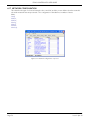
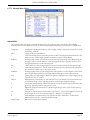
7.4 PARAMETER EXPLORER . . . . . . . . . . . . . . . . . . . . . . . . . . . . . . . . . . . . . . . . . . . . . . .
Figure 7.4.1 Parameter explorer detail . . . . . . . . . . . . . . . . . . . . . . . . . . . . . . . . . . .
7.4.2 Explorer tools . . . . . . . . . . . . . . . . . . . . . . . . . . . . . . . . . . . . . . . . . . . . . . . . . . . .
7.4.3 Context Menu . . . . . . . . . . . . . . . . . . . . . . . . . . . . . . . . . . . . . . . . . . . . . . . . . . .
7.5 FIELDBUS GATEWAY . . . . . . . . . . . . . . . . . . . . . . . . . . . . . . . . . . . . . . . . . . . . . . . . . .
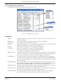
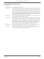
7.6 WATCH/RECIPE EDITOR . . . . . . . . . . . . . . . . . . . . . . . . . . . . . . . . . . . . . . . . . . . . . . .
7.6.1 Creating a Watch List . . . . . . . . . . . . . . . . . . . . . . . . . . . . . . . . . . . . . . . . . . . . . .
ADDING PARAMETERS TO THE WATCH LIST . . . . . . . . . . . . . . . . . . . . . . . . . .
DATA SET CREATION . . . . . . . . . . . . . . . . . . . . . . . . . . . . . . . . . . . . . . . . . . . . . . .
7.6.2 Watch Recipe toolbar icons . . . . . . . . . . . . . . . . . . . . . . . . . . . . . . . . . . . . . . . . . . .
7.6.3 Watch/Recipe Context Menu . . . . . . . . . . . . . . . . . . . . . . . . . . . . . . . . . . . . . . .
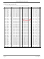
8 PARAMETER ADDRESSES (MODBUS) . . . . . . . . . . . . . . . . . . . . . . . . . . . . . . . . . . . .
8.1 INTRODUCTION . . . . . . . . . . . . . . . . . . . . . . . . . . . . . . . . . . . . . . . . . . . . . . . . . . . . . .
8.2 PARAMETER TYPES . . . . . . . . . . . . . . . . . . . . . . . . . . . . . . . . . . . . . . . . . . . . . . . . . . . .
8.3 PARAMETER SCALING . . . . . . . . . . . . . . . . . . . . . . . . . . . . . . . . . . . . . . . . . . . . . . . . .
8.4 PARAMETER LIST . . . . . . . . . . . . . . . . . . . . . . . . . . . . . . . . . . . . . . . . . . . . . . . . . . . . .
9 ALARMS . . . . . . . . . . . . . . . . . . . . . . . . . . . . . . . . . . . . . . . . . . . . . . . . . . . . . . . . . . . . . . .
9.1 SYSTEM ALARMS . . . . . . . . . . . . . . . . . . . . . . . . . . . . . . . . . . . . . . . . . . . . . . . . . . . . .
9.1.1 Missing mains . . . . . . . . . . . . . . . . . . . . . . . . . . . . . . . . . . . . . . . . . . . . . . . . . . . .
9.1.2 Thyristor short circuit . . . . . . . . . . . . . . . . . . . . . . . . . . . . . . . . . . . . . . . . . . . . . .
9.1.3 Thyristor open circuit . . . . . . . . . . . . . . . . . . . . . . . . . . . . . . . . . . . . . . . . . . . . . .
9.1.4 Over temperature . . . . . . . . . . . . . . . . . . . . . . . . . . . . . . . . . . . . . . . . . . . . . . . .
9.1.5 Network dips . . . . . . . . . . . . . . . . . . . . . . . . . . . . . . . . . . . . . . . . . . . . . . . . . . . .
9.1.6 Mains frequency fault . . . . . . . . . . . . . . . . . . . . . . . . . . . . . . . . . . . . . . . . . . . . .
9.1.7 Chop Off alarm . . . . . . . . . . . . . . . . . . . . . . . . . . . . . . . . . . . . . . . . . . . . . . . . . . .
9.2 PROCESS ALARMS . . . . . . . . . . . . . . . . . . . . . . . . . . . . . . . . . . . . . . . . . . . . . . . . . . . .
9.2.1 Total Load Failure (TLF) . . . . . . . . . . . . . . . . . . . . . . . . . . . . . . . . . . . . . . . . . . .
9.2.2 Closed Loop alarm . . . . . . . . . . . . . . . . . . . . . . . . . . . . . . . . . . . . . . . . . . . . . . . .
9.2.3 Alarm input . . . . . . . . . . . . . . . . . . . . . . . . . . . . . . . . . . . . . . . . . . . . . . . . . . . . . .
9.2.4 Over current detection . . . . . . . . . . . . . . . . . . . . . . . . . . . . . . . . . . . . . . . . . . . .
9.2.5 OverVoltage Alarm . . . . . . . . . . . . . . . . . . . . . . . . . . . . . . . . . . . . . . . . . . . . . . .
9.2.6 UnderVoltage Alarm . . . . . . . . . . . . . . . . . . . . . . . . . . . . . . . . . . . . . . . . . . . . . .
9.2.7 Partial Load Failure (PLF) . . . . . . . . . . . . . . . . . . . . . . . . . . . . . . . . . . . . . . . . . . .
Page iv
56
57
57
58
58
60
60
61
61
62
62
63
63
64
64
64
64
67
68
69
70
70
71
73
74
77
79
80
81
81
82
84
84
84
84
85
85
86
86
86
86
86
87
87
87
87
87
87
87
87
87
87
87
87
87
88
88
88
88
HA031414
Issue 1 Apr 13
EPACK CONTROLLER: USER GUIDE
List of Contents (Cont.)
Section
9.3 INDICATION ALARMS . . . . . . . . . . . . . . . . . . . . . . . . . . . . . . . . . . . . . . . . . . . . . . . . .
9.3.1 Process Value Transfer active . . . . . . . . . . . . . . . . . . . . . . . . . . . . . . . . . . . . . . .
9.3.2 Limitation active . . . . . . . . . . . . . . . . . . . . . . . . . . . . . . . . . . . . . . . . . . . . . . . . . .
9.3.3 Load Over-Current . . . . . . . . . . . . . . . . . . . . . . . . . . . . . . . . . . . . . . . . . . . . . . . .
10 MAINTENANCE . . . . . . . . . . . . . . . . . . . . . . . . . . . . . . . . . . . . . . . . . . . . . . . . . . . . . . .
10.1 SAFETY . . . . . . . . . . . . . . . . . . . . . . . . . . . . . . . . . . . . . . . . . . . . . . . . . . . . . . . . . . . . . .
10.2 PREVENTIVE MAINTENANCE . . . . . . . . . . . . . . . . . . . . . . . . . . . . . . . . . . . . . . . . . .
10.3 FUSING . . . . . . . . . . . . . . . . . . . . . . . . . . . . . . . . . . . . . . . . . . . . . . . . . . . . . . . . . . . . . .
Appendix A: TECHNICAL SPECIFICATION . . . . . . . . . . . . . . . . . . . . . . . . . . . . . . . . . . .
A1 STANDARDS . . . . . . . . . . . . . . . . . . . . . . . . . . . . . . . . . . . . . . . . . . . . . . . . . . . . . . . . . .
A2 SPECIFICATION . . . . . . . . . . . . . . . . . . . . . . . . . . . . . . . . . . . . . . . . . . . . . . . . . . . . . . .
INDEX . . . . . . . . . . . . . . . . . . . . . . . . . . . . . . . . . . . . . . . . . . . . . . . . . . . . . . . . . . . . . . . . . . .
HA031414
Issue 1 Apr 13
Page
89
89
89
89
90
90
90
91
93
93
93
i
Page v
EPACK CONTROLLER: USER GUIDE
This page is deliberately left blank
Page vi
HA031414
Issue 1 Apr 13
EPACK CONTROLLER: USER GUIDE
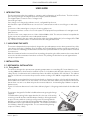
SAFETY NOTES
WARNING
BRANCH-CIRCUIT PROTECTION AND SAFETY OVERLOAD PROTECTION
This product does not contain any branch-circuit protection or internal safety overload protection. It
is the responsibility of the user to add branch-circuit protection upstream of the unit. It is also the
responsibility of the user to provide external or remote safety overload protection to the end installation. Such branch-circuit and safety oveload protection must comply with applicable local regulations.
UL: The abovementioned branch-circuit protection is necessary for compliance with National Electric
Code (NEC) requirements.
1.
2.
3.
4.
5
WARNINGS
Any interruption of the protective conductor inside or outside the apparatus, or disconnection of
the protective earth terminal is likely to make the apparatus dangerous under some fault conditions. Intentional interruption is prohibited.
Before carrying out any wiring to the unit it must be ensured that all relevant power and control
cables, leads or harnesses are isolated from voltage sources. Wire conductor cross sections must
comply with table 1 of EN60947-1 (or with table 2.2.1 of this manual).
This equipment is not suitable for isolation applications, within the meaning of EN60947-1.
Under some circumstances, the power module heatsink temperature may rise above 50 degrees
Celsius. If operators are likely to come into contact with such heatsinks, adequate warnings and
barriers must be put in place in order to prevent injury.
EPack alarms protect thyristors and loads against abnormal operation, and provide the user with
valuable information regarding the type of fault. Under no circumstances should these alarms be
regarded as a replacement for proper personnel protection. It is strongly recommended that the
installing authority include independent, system-safety mechanisms to protect both personnel
and equipment against injury or damage, and that such safety mechanisms be regularly inspected and maintained. Consult the EPack supplier for advice.
Note:
The instrument shall have one of the following as a disconnecting device, fitted within easy reach of
the operator, and labelled as the disconnecting device.
a. A switch or circuit breaker which complies with the requirements of IEC947-1 and IEC947-3
b. A separable coupler which can be disconnected without the use of a tool.
1.
2.
3.
4.
5.
Before any other connection is made, the protective earth terminal shall be connected to a protective
conductor.
Whenever it is likely that protection has been impaired, the unit shall be made inoperative, and
secured against accidental operation. The manufacturer’s nearest service centre should be contacted
for advice.
Any adjustment, maintenance and repair of the opened apparatus under voltage, is forbidden for
safety reasons.
Units are designed to be installed in a cabinet connected to the protective earth according to IEC364
or applicable national standards. The cabinet must be closed under normal operating conditions. Adequate air conditioning/ filtering/ cooling equipment must be fitted to the cabinet in order to prevent
the ingress of conductive pollution, the formation of condensation etc.
Units are designed to be mounted vertically. There must be no obstructions (above or below) which
could reduce or hamper airflow. If more than one set of units is located in the same cabinet, they must
be mounted in such a way that air from one unit is not drawn into another.
HA031414
Issue 1 Apr 13
Page 1
EPACK CONTROLLER: USER GUIDE
SAFETY NOTES (Cont.)
6. Signal and power voltage wiring must be kept separate from one another. Where this is impractical,
shielded cables should be used for the signal wiring.
7. If the equipment is used in a manner not specified by the manufacturer, the protection provided by the
equipment might be impaired.
8. This product has been designed for environment A (Industrial). Use of this product in environment B
(domestic, commercial and light industrial) may cause unwanted electromagnetic disturbances in
which cases the user may be required to take adequate mitigation measures.
SELV
Safety Extra Low Voltage. This is defined (in EN60947-1) as an electrical circuit in which the voltage cannot
exceed ‘ELV’ under normal conditions or under single fault conditions, including earth faults in other circuits.
The definition of ELV is complex as it depends on environment, signal frequency etc. See IEC 61140 for further details.
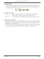
SYMBOLS USED IN THE INSTRUMENT LABELLING
One or more of the symbols below may appear as a part of the instrument labelling.
Protective conductor terminal
Risk of electric shock
AC supply only
Precautions against static electrical discharge
must be taken when handling this unit
Underwriters Laboratories listed
mark for Canada and the US
!
Refer to the manual for instructions
Do not touch Heatsink
Hot Surface
Page 2
HA031414
Issue 1 Apr 13
EPACK CONTROLLER: USER GUIDE
USER GUIDE
1 INTRODUCTION
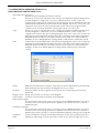
This document describes the installation, operation and configuration of an EPack unit. The Unit includes
the following analogue and digital inputs and outputs, fitted as standard:
Two digital inputs (contact closure or voltage level)
One analogue input
One change-over relay under software control, configurable by the user.
Also fitted are a pair of RJ45 Ethernet connectors for communications with a controlling pc or with other
units.
Section two of this manual gives connector locations and pinouts.
The operator interface consists of a 1.5 inch square TFT display and four push buttons for navigation and
data selection.
The unit comes in two output versions: 16A to 32A and 40A to 63A. The units are identical except that the
higher power unit is fitted with a more substantial heatsink.
The supply voltage for the units can be specified as either low voltage (24V ac/dc) or line voltage (85 to 550V
ac). The choice is made at time of order and cannot be changed in the field.
1.1 UNPACKING THE UNITS
The units are despatched in a special pack, designed to give adequate protection during transit. If any of the
outer boxes show signs of damage, they should be opened immediately, and the instrument examined. If
there is evidence of damage, the instrument should not be operated and the local representative contacted
for instructions.
After the instrument has been removed from its packing, the packing should be examined to ensure that all
accessories and documentation have been removed. The packing should then be stored against future
transport requirements.
2 INSTALLATION
2.1 MECHANICAL INSTALLATION
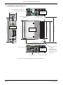
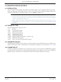
2.1.1 Fixing details
The units are designed to operate at an operating temperature not exceeding 45°C at an altitude not exceeding 1000 metres. Units must be installed in a fan-cooled cabinet (with fan failure detection or thermal
safety cutout). Condensation and conductive pollution should be excluded to IEC 664 class 2. The cabinet
must be closed and connected to the protective earth according to IEC 60634 or applicable national standard.
Units must be mounted with the heat sink vertical with no obstructions above or below which impede the
airflow. Where more than one set of modules is enclosed in the same cabinet, they must be mounted such
that air from one unit is not drawn in by another mounted above it. A minimum gap of 10mm is required
between units.
Figure 2.1.1a shows dimensions for the 16A to 32A unit; figure 2.1.1b giving similar details for the 40 to 63A
unit.
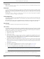
The units are designed for Din Rail or bulkhead mounting using the fixings
supplied.
For Bulkhead mounting, fit the upper bracket ‘A’ to the rear of the unit by
removing screw ‘B’ and associated shakeproof washer, offering the bracket up to the unit, and then securing it using screw ‘B’ ensuring that the
bracket is correctly oriented (as shown) and that the shakeproof washer is
fitted between the screw head and the bracket. The relevant screwdriver
should have a 3mm AF hexagonal bit. The recommended tightening
torque is 1.5Nm (1.1 lb-ft).
HA031414
Issue 1 Apr 13
A
B
Page 3
EPACK CONTROLLER: USER GUIDE
2.1.1 MECHANICAL INSTALLATION (Cont.)
24V
AC/DC
EPack (auxiliary) supplypower
(low voltage option shown)
N/L2
51mm (2.01 in)
View on
upper face
46.7mm (1.84 in)
136.2mm (5.36 in)
174mm (6.85 in)
View on righthand side
147mm (4.79 in)
Load power input
117mm (4.61 in)
121mm (4.76 in)
Front view
129.2mm (5.09 in)
163.5mm (6.44 in)
Phase reference
(neutral)
M5
1 2 3 4 5
I/O connector
04 01 02
Relay output
View on
lower face
Safety earth connection (M5 nut).
The earth connection must be made
using a Listed ring
type crimp.
Load power output
Figure 2.1.1a mechanical installation details (16A to 32A units).
Page 4
HA031414
Issue 1 Apr 13
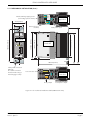
EPACK CONTROLLER: USER GUIDE
2.1.1 MECHANICAL INSTALLATION (Cont.)
24V
AC/DC
EPack (auxiliary) supply power
(low voltage option shown)
N/L2
View on
upper face
72mm (2.83 in)
46.7mm (1.84 in)
M5
158.2mm (6.23 in)
1 2 3 4 5
Safety earth connection
(M5 nut).
The earth connection
must be made using a
Listed ring type crimp.
174mm (6.85 in)
View on righthand side
147mm (4.79 in)
Load power input
117mm (4.61 in)
121mm (4.76 in)
163.5mm (6.44 in)
Front view
129.2mm (5.09 in)
Phase reference
(neutral)
I/O connector
04 01 02
Relay output
View on
lower face
Load power output
Figure 2.1.1b mechanical installation details (40A to 63A units).
HA031414
Issue 1 Apr 13
Page 5
EPACK CONTROLLER: USER GUIDE
2.2 ELECTRICAL INSTALLATION
CAUTION
It must be ensured that an effective strain relief mechanism (e.g. trunking) is in place for all EPack cables. Failure to ensure this may result in the unintentional disconnection of one of more connectors
resulting in unexpected and possibly dangerous lack of control.
2.2.1 EPack supply voltage
The supply voltage connections (to operate the Epack unit) are terminated using a 2-way (24V ac/dc version)
or 3-way (85 to 550Vac version) connector, located on the upper side of the unit, as shown in figure 2.2 , below.
The supply voltage 85Vac to 550Vac shall be protected by ATM2 rated 600Vac/dc, 2A by MERSEN/Ferraz
Shawmut(E33925)
In order to protect the wiring it is recommended that a branch circuit fuse be incorporated. (1Amp for
24Vac/dc supplies and 2 Amp for 85 to 550Vac supplies)
A safety earth connection must be made to the unit with a Listed ring type crimp terminal, using the M5 nut
and shakeproof washer supplied.
CONNECTION DETAILS
Table 2.2.1 below, gives details of wire sizes and tightening torques for the various supply power and signal
wiring connections.
Where a range of wire sizes is given it is up to the user to select the correct cross sectional area required for
the application. The safety earth cable should be, as a minimum, of the same cross sectional area as the cables used for the load (i.e. the cables terminated at the 1/L1 and 2/T1 terminals).
Connector
Cable cross section and tightening torque
Supply voltage (1/L1) and
16 to 32 A units: 2.5 to 6 mm² (12 to 10 AWG). Torque: 1.7 Nm
Load supply (2/T1)
40 to 63 A units: 10 to 16 mm² (8 to 6 AWG). Torque: 1.7 Nm
Safety earth
Cross section same as above. Torque 2.5 Nm
Phase reference (N/L2) (2-way)
0.25 to 2.5 mm² (24 to 12 AWG). Torque 0.6 Nm.
EPack supply (24V ac/dc) (2-way)
0.25 to 2.5 mm² (24 to 12 AWG). Torque 0.6 Nm.
EPack supply (88 to 550V ac) (3-way)
0.25 to 2.5 mm² (24 to 12 AWG). Torque 0.6 Nm.
I/O connector (5-way)
0.25 to 2.5 mm² (24 to 12 AWG). Torque 0.6 Nm.
Relay connector (3-way)
0.25 to 2.5 mm² (24 to 12 AWG). Torque 0.6 Nm.
2.5Nm = 22.13 pound inches; 1.7Nm = 15.05 pound inches; 0.6Nm = 5.31 pound inches.
Table 2.2.1 Cable details
Notes:
1. Temperature rating of field-installed power conductors (Supply, Load and Safety earth): 90°C;
Temperature rating of other wires : 75°C
2. An 0.6 x 3.5 mm flat-blade screwdriver should be used for pluggable connectors
Page 6
HA031414
Issue 1 Apr 13
EPACK CONTROLLER: USER GUIDE
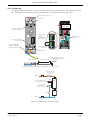
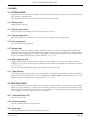
2.2.2 Load wiring
The supply voltage for the load is connected at the terminal located in the centre of the upper side of the
unit. The load is connected at the terminal located in the centre of the lower side of the unit.
From Supply power for load
Lift-up flap
View on
upper face
Access to supply termination screw head
Supply voltage
alternatives
(as specified at
time-of-order)
Neutral reference
(either pin)
Access to load termination screw head
N/L2
Safety earth (M5 nut).
Must be made with a
Listed ring type crimp
Centre pin not
connected
Pull-down flap
To load
Insulated handle
Flat-bladed screw head
0.6 x 4.5 mm or 0.8 x 4.5mm
recommended
60mm minimum
Screwdriver/Torque wrench screwdriver bit details for line and load termination
High speed thyristor
protection fuse
(section 10.3)
Supply
Isolating device
1/L1
Fuse
EPack auxiliary supply
(low voltage option shown)
EPack
Phase/neutral
reference connector
(use either terminal)
N/L2
2/T1
Load
Fuse
Return
Isolating device
Figure 2.2.2 Supply power connection details
HA031414
Issue 1 Apr 13
Page 7
EPACK CONTROLLER: USER GUIDE
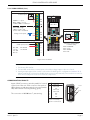
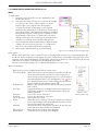
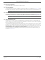
2.2.3 Signal wiring
Figure 2.2.3 shows the connector location, on the underside of the unit, for the digital and analogue inputs,
and for the internal relay output.
ENABLE INPUT
In order for the power module thyristors to operate, the Enable input must be valid, In the default configuration, this is achieved by shorting pins 0V and DI1 of the I/O connector located on the underside of the unit
(Digital input 1), or by using a User Value block to apply a logic high to the enable input to the relevant firing
block in iTools.
If required, DI1 can be configured as a voltage input, and in this case it requires a high signal to be applied
to D1 with the relevant zero voltage connected to 0V.
ALARM ACKNOWLEDGE
In the default configuration, shorting pins 0V and DI2 of the I/O connector located on the underside of theunit (Digital input 2) acknowledges alarms. As an alternative, a logic input can be wired to the relevant parameter using iTools.
If the graphical wiring editor option is enabled DI2 can be configured as a voltage input (if required), and in
this case it requires a high signal to be applied to D2 with the relevant zero voltage connected to 0V.
MAIN SETPOINT
In the default configuration, the analogue input sets the main setpoint.
RELAY OUTPUT
In the default configuration, the relay output is operated by any alarm becoming active. The relay is normally
energised (common and normally open shorted), and is de-energised (common and normally closed shorted) when active. In addition to the normal channel etc. alarms, if any of the following errors are detected,
the watchdog alarm becomes active and de-energises the relay.
1. Missing mains. Supply voltage line is missing.
2. Thyristor short circuit*
3. Thyristor open circuit*
4. Network dips. A reduction in supply voltage exceeding a configurable value (VdipsThreshold), causes
firing to be inhibited until the supply voltage returns to a suitable value. VdipsThreshold represents a
percentage change in supply voltage between successive half cycles, and can be defined by the user
in the Network.Setup menu, as described in section 6.17.2
5. Supply frequency fault. The supply frequency is checked every half cycle, and if the percentage change
between successive 1/2 cycles exceeds a threshold value (max. 5%), a Mains Frequency System Alarm
is generated. The threshold value (FreqDriftThold) is defined in the Network.Setup menu described in
section 6.17.2
6. Supply failure to Epack unit.
7. Line under voltage (configurable between 2 and 15% of nominal voltage) (section 6.17.2).
8. Line over voltage (configurable between 2 and 15% of nominal voltage) (section 6.17.2).
9 Over current (configurable between 10 and 400% of nominal current) (section 6.17.2).
* Note... It is not possible to detect a thyristor short circuit when the unit is delivering 100% output
power. Similarly, it is not possible to detect thyristor open circuit when the unit is delivering 0% output.
It is possible, using iTools to wire the relay to become active under the control of any suitable parameter.
If the watchdog resets the unit, the relay is de-energised temporarily then re-energised at start-up.
Page 8
HA031414
Issue 1 Apr 13
EPACK CONTROLLER: USER GUIDE
2.2.3 SIGNAL WIRING (Cont.)
Digital inputs
Contact inputs
1
0V
+
0V
500Ω to ∞ = open
0Ω to 150Ω = closed
150Ω to 500Ω = undefined
1
0V
+
0 to 20 mA
4 to 20 mA
1
0V
01
nc
1 2 3 4 5
0 to 10V
1 to 5V
2 to 10V
0 to 5V
02
DI1
DI2
V/mA input (note 3)
Relay output
0V
Voltage level inputs
Analogue input
View on
lower face
DI2
04 01 02
4.4 to 30V = high
-30V to +2.3V = low
2.3V to 4.4V = undefined
DI1
com
no
04
Switching characteristics
(resistive loads)
Vmax: 264V RMS
Vmin: 1V dc
Imax: 2A RMS
Imin: 1mA
+
0V
DI1
DI2
Figure 2.2.3 I/O details
Notes:
1. DI1 shown; DI2 similar
2. DI1 and DI2 can both be contact inputs or both be voltage inputs or be one of each.
3. Analogue input type (Volts or mA) is selected in I/O Analogue IP configuration (section 6.11.1).
When a mA range is selected, a suitable shunt resistor is automatically connected into circuit. It is
thus unnecessary for the user to fit external components.
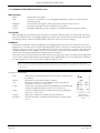
COMMUNICATIONS PINOUTS
A pair of RJ45 connectors, wired in parallel is located
on the front of the unit. Each connector has a pair of
LED indicators to indicate network connection (amber
LED) and network Tx activity (flashing green).
The connection is 10/100 base T, autosensing.
HA031414
Issue 1 Apr 13
Pin
Signal
Not used
8
Not used
7
Rx6
Not used
5
Not used
4
Rx+
3
Tx2
Tx+
1
LEDs:
Green = Tx activity
Yellow = Connected
8
Yellow
1
8
Green
1
Page 9
EPACK CONTROLLER: USER GUIDE
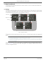
3 OPERATOR INTERFACE
Located at the front of the Driver Module, the operator interface consists of a 26mm square display, and,
four push-button switches.
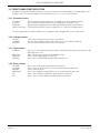
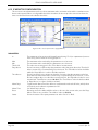
3.1 DISPLAY
The display is divided vertically into three areas, which for the purposes of this manual are called the status
area at thetop, the data display, in the centre, and the softkeys at the bottom. This display, together with the
four pushbuttons allows full operation and configuration of the unit.
Status area
Display area
Softkeys
Figure 3 Operator interface
The figure above shows a typical operator mode screen set, scrolled through using the return (page) pushbutton.
Notes:
1. The Energy display appears only if the Energy option is fitted
2. The Alarms display appears only if there are any active alarms. The up/down arrow pushbuttons
can be used to scroll through the alarm list, if there are more alarms active than can be displayed
on one screen height.
The ‘Goto’ item allows the user to enter Engineer or Configuration mode, providing the password(s) are
known. Section 5.1.3 describes the procedure, although the screen displays are different because the unit
is shown in configuration mode.
Page 10
HA031414
Issue 1 Apr 13
EPACK CONTROLLER: USER GUIDE
3.2 PUSHBUTTONS
The functions of the four pushbuttons below the display depend on what is displayed in the softkey area.
The leftmost pushbutton (Return) is associated with the leftmost softkey, the down arrow pushbutton is
associated with the next softkey and so on. In the example above, the ‘Return’ key is used both to enter the
Menu, and to return from it to the initial display.
Return
Scroll
Down
Scroll
Up
Enter
3.2.1 Pushbutton functions
Return
Scroll down/up
Enter
Returns to previous menu (while menus are displayed), cancels editing (during
parameter editing), and performs screen cycling (during operator mode).
Allows the user to scroll through the available menu items or values.
Goes to next menu item. In parameter edit mode, this button confirms the changes.
3.2.2 Menu item value selection
Menu items are scrolled through using the up/down pushbuttons. Once the required item is displayed, the
Enter pushbutton is used to select it for editing. Editing of the item’s value is carried out by scrolling through
the available choices, using the up and down scroll keys. Once the desired value is displayed, the Enter
pushbutton is used to confirm the choice.
Where multiple changes have to be made (as in editing an IP address for example), the Enter pushbutton
acts as a right cursor key, moving from the field just edited to the next field. (The Return key moves the cursor
left). Once all fields have been edited, the enter key is used a final time to confirm the choice.
HA031414
Issue 1 Apr 13
Page 11
EPACK CONTROLLER: USER GUIDE
3.3 FRONT PANEL EVENT INDICATION
A number of instrument alarms and events can occur, and these are indicated by icons appearing on the
display screen. The events and alarms are listed below. See section 9 for a more details.
3.3.1 Instrument events
Conf Entry
Conf Exit
GlobalAck
Quick Code Entry
The instrument has been placed in configuration mode (cogwheel symbol).
The instrument has been taken out of configuration mode (no icon).
A global acknowledgement of all safe latched alarms has been performed.
The Quick Code menu is active (cogwheel icon + ‘QCode’ in display area).
The following alarms all cause a red bell icon to appear in the top right hand corner of the screen.
3.3.2 Indication alarms
LimitAct
LoadOverI
PrcValTfr
One or more limits are active in the control block
An over current alarm has become active in one or more Network blocks.
Process value transfer is active inthe control block.
3.3.3 System alarms
FuseBlown
MainsFreq
Missmains
NetwDip
There is no internal fuse, but it is possible to use DI2as a ‘fuse-blown’ input wired to the
alarm block in iTools.
Mains Frequency is outside the acceptable range.
One or more supply phases is missing.
One or more ‘network dip’ alarms has been detected.
3.3.4 Process alarms
ChopOff
ClosedLp
InputBrk
MainVFault
PLF
TLF
Page 12
One or more ‘Chop-off’ alarm has been detected.
One or more Control block ‘Closed Loop’ alarm has been detected.
Over current in shunt.
One or more ‘Mains Voltage Fault’ (over or under) has been detected.
One or more ‘Partial Load Failure’ alarm has been detected.
One or more ‘Total Load failure’ alarm has been detected.
HA031414
Issue 1 Apr 13
EPACK CONTROLLER: USER GUIDE
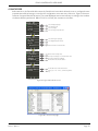
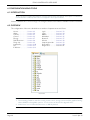
4 QUICKCODE
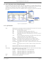
At first switch-on, the Driver Module enters the ‘QuickCode’ menu which allows the user to configure the major parameters without having to enter the full configuration menu structure of the unit. Figure 4 shows an
overview of a typical QuickCode menu. The actual displayed menu items will vary according to the number
of software features purchased. When ‘Finish’ is selected, the instrument cold starts.
Select Lang.
Firing
Heater
AI_Fct
AI_Type
DI2_Fct
XFrmr
I_Nominal
Select display language
Select firing mode
Select load type
Select analogue input function
Select Analogue input type
Select Digital input 2 function
Enter nominal load current value
V_Nominal
Link Speed
IPMode
IP address
Enter nominal voltage value
Select speed and type of communications link
Select IP mode (Fixed or DHCP)
For fixed IP mode enter IP address
Subnet Mask
Finish
For fixed IP mode enter Subnet mask
Select ‘yes’ or ‘no’. If ‘Yes’, confirm using ‘Enter
key
Figure 4a Typical QuickCode menu
Figure 4b iTools Qcode page
HA031414
Issue 1 Apr 13
Page 13
EPACK CONTROLLER: USER GUIDE
4 QUICKCODE MENU (Cont.)
Notes:
1. If the unit has been fully configured at the factory, the Quickcode menu will be skipped, and the
unit will go into operation mode at first switch on.
2. Once quit, the Quickcode menu can be returned to at any time from the Access menu (described
later in this document (section 6)). Returning to the Quickcode menu cold-starts the unit.
4.1 QUICKCODE MENU PARAMETERS
Language
Firing Mode
Heater
En_Limit
En_Transfer
Control
AI Fct
AI Type
DI2 Fct
XFRMR
I Nominal
V Nominal
Link Speed
IP Mode
IP Address
SubNetMask
Finish
Page 14
Initially, English, French, German and Italian may be selected. Other languages may be
added during the lifetime of this issue of the manual. Once confirmed all further displays appear in the selected language.
Select from LG (Logic), BF (Burst Variable), FX (Burst Fixed), HC (Hal fCycle) or PA (Phase
Angle).
Select from R (Resistive), IR (Infra red), CS (Silicon carbide) or MO (Molybdenum disilicide)
Used to enable/disable threshold limit.
Select Transfer Enable (Proportional limit) as ‘Yes’ (enabled) or ‘No’ (not enabled).
Select VSq or Power
Select SP (setpoint), HR (setpoint limit), CL (current limit), TS (transfer limit) or XX (no
function) as Analogue Input function
Select 0V (0 to 10V), 1V (1 to 5V), 2V (2 to 10V), 5V (0 to 5V), 0A (0 to 20mA) or 4A (4 to
20 mA) as analogue input type.
AK (Alarm acknowledge), RS (Remote setpoint), FB (Fuse Blown), or XX (none)
XX (Resistive load type) TR (Transformer primary)
A value, normally between the maximum current the unit can safely sustain and a quarter of this value. (Lower values are not recommended as in such cases, the resulting accuracy and linearity are not guaranteed to be within specification.) Default value
appears. Use up/down arrow buttons to edit.
A value between the maximum permanent supply voltage (+10%) to the modules, and
a quarter of this value. Default value appears. Use up/down arrow buttons to edit.
Select from ‘AutoNego’, 100Mb, 100 Mb Half duplex, 10 Mb, 10Mb Half duplex.
Choose ‘Fixed’ or ‘DHCP’
For fixed mode, allows the IP address to be edited, one section at a time. Use the updown arrow pushbuttons to edit the first section (XXX.xxx.xxx.xxx), then ‘Enter’ to move
to the next section (xxx.XXX.xxx.xxx) and repeat until all four sections are as required
As for IP address above, but for the subnet mask.
If confirmed, Finish quits quick start and the instrument restarts.
HA031414
Issue 1 Apr 13
EPACK CONTROLLER: USER GUIDE
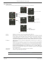
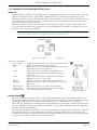
4.2 SOME DEFINITIONS
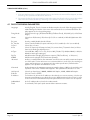
4.2.1 Firing modes
LOGIC
Power switches on, two or three zero crossings of the supply voltage after the logic input switches on. Power
switches off two zero crossings of current after the logic input switches off. For resistive loads, voltage and
current cross zero simultaneously. With inductive loads, a phase difference exists between the voltage and
current, meaning that they cross zero at different times. The size of the phase difference increases with
increasing inductance.
Power on-off delay = two or three mains
periods depending on where in the mains
cycle the logic output changes state.
Power applied
Logic output from controller
Figue 4.2.1a Logic firing mode
BURST FIXED FIRING
This means that there is a fixed ‘cycle time’ equal to an integer number of supply voltage cycles as set up in
the Modulator menu. Power is controlled by varying the ratio between the on period and the off period
within this cycle time (figure 4.2.1b).
Tcyc
Power applied
Ton
Power applied
Toff
Ton
Tcyc = Ton + Toff
Figure 4.2.1b Burst Fixed mode
HA031414
Issue 1 Apr 13
Page 15
EPACK CONTROLLER: USER GUIDE
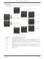
4.2.1 FIRING MODES (Cont.)
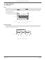
BURST VARIABLE FIRING
Burst Firing Variable is the preferred mode for temperature control. Between 0 and 50% of setpoint, the on
time is the ‘Min on’ time set in the modulator menu and the off time is varied to achieve control. Between
50% and 100%, the off time is the value set for ‘Min on’ and power is controlled by varying the number of on
cycles.
Power
Power
Power applied
applied
Power applied
Min off
Ton
Toff
Ton
Ton
Toff = 1/2 Min on = 66.7% duty cycle
Toff
Min on
Ton
Toff = Min on = 50% duty cycle
Power applied
Power applied
Min on
Min On = Min Off = 2
for these examples
applied
Min on Min off
Ton
Toff
Ton
Toff = 2 x Min on = 33.3% duty cycle
Figure 4.2.1c Burst variable firing
PHASE ANGLE CONTROL
This mode of firing controls power by varying the amount of each cycle which is applied to the load, by
switching the controlling thyristor on part-way through the cycle. Figure 4.2.1d shows an example for 50%
power.
50% shown.
Power is proportional to the area
under the curve
On
On
On
On
On
On
On
On
Figure 4.2.1d Phase angle mode
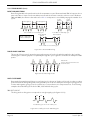
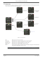
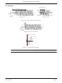
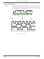
HALF CYCLE MODE
Burst mode firing with a single firing (or non-firing) cycle is known as ‘Single cycle’ mode. In order to reduce
power fluctuations during firing time, Intelligent half-cycle mode uses half cycles as firing/non-firing periods.
Positive and negative going cycles are evened out, to ensure that no dc component arises. The following
examples describe half-cycle mode for 50%, 33% and 66% duty cycles.
50% DUTY CYCLE
The firing and non-firing time corresponds to a single supply cycle (figure 4.2.1e).
Ton
Toff
For 50% duty cycle Tn = Toff = 2 half cycles
Figure 4.2.1e Half cycle mode: 50% duty cycle
Page 16
HA031414
Issue 1 Apr 13
EPACK CONTROLLER: USER GUIDE
4.2.1 FIRING MODES (Cont.)
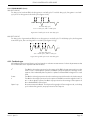
33% DUTY CYCLE
For duty cycles less than 50%, the firing time is one half-cycle. For a 33% duty cycle, firing time is one half
cycle; the non-firing time is two half-cycles (figure 4.2.1f).
Ton
Toff
Ton
Toff
For 33% duty cycle
Ton = 1 half cycle; Toff = 2 half cycles
Figure 4.2.1f Half cycle mode: 33% duty cycle
66% DUTY CYCLE
For duty cycles of greater than 50%, the non-firing time is one half-cycle. For 66% duty cycle, the firing time
is two half cycles; the non-firing time is one half cycle (figure 4.2.1g).
Ton
Toff
Ton
Toff
For 66% duty cycle
Ton = 2 half cycles; Toff = 1 half cycle
Figure 4.2.1g Half cycle mode: 66% duty cycle
4.2.2 Feedback type
All feedback types (except ‘Open Loop’) are based on real-time measurement of electrical parameters that
are normalised to their equivalent Nominal values.
V2
Power
I2
Open loop
HA031414
Issue 1 Apr 13
Feedback is directly proportional to the square of the RMS voltage measured across the
load. For two- or three-phase systems, feedback is proportional to the average of the
squares of the individual phase-to-phase or phase-to-Neutral RMS voltage across each
load.
Feedback is directly proportional to the total true power delivered to the load network.
Feedback is directly proportional to the square of the RMS current through the load. For
two- or three-phase systems, feedback is proportional to the average of the squares of
the individual RMS load currents.
No measurement feedback. The thyristor firing angle in Phase angle mode, or the duty
cycle in burst-firing mode, are proportional to the setpoint.
Page 17
EPACK CONTROLLER: USER GUIDE
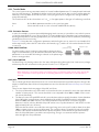
4.2.3 Transfer Mode
The control system can use automatic transfer of certain feedback parameters. For example with loads with
very low cold resistance, I2 feedback should be used to limit inrush current, but once the load has started to
warm up, Power feedback should be used; the control program can be configured to change feedback
mode automatically.
The Transfer mode can be selected as I2 to P or Irms to P as appropriate to the type of load being controlled.
None
I2
No feedback parameter transfer to the control program.
Selects transfer mode: I2 to the selected Feedback Mode (above).
4.2.4 Limitation features
In order, for example, to prevent potentially damaging inrush currents, it is possible to set a value for power
or Current squared which is not to be exceeded. For loads exhibiting a low impedance at low temperatures
but a higher impedance at working temperature, the current drawn reduces as the load warms, and limiting
gradually becomes unnecessary.
Section 6.6.3 describes the configuration parameters which allow the user to enter a Process Variable (PV)
and a setpoint (SP), where the PV is the value to be limited (e.g. I2) and the SP is the value that the PV must
not exceed.
FIRING ANGLE LIMITING
Limiting
(gradually reducing)
Target phase angle
For phase angle control, limiting is achieved by reducing the firing
angle on each half mains cycle such that the limit value of the relevant
parameter is not exceeded. As limiting is reduced so the phase angle
tends to its target value.
DUTY CYCLE LIMITING
For Burst Firing only, limiting reduces the ‘On’ state of the burst firing driving the load. Load current, voltage
and active power are calculated over the period of each (Ton + Toff) period.
CAUTION
When applied to load current, duty cycle limiting does not limit the peak current value, and under
some circumstances this may allow an overheating hazard in the load and/or Power Module to
develop.
CHOP OFF
This is a limiting technique which detects an over-current alarm state and stops further thyristor firing for the
duration of that alarm state. All the relevant parameters are to be found in the Network Setup menu (section
6.17.2).
There are two alarms which may trigger Chop Off, as follows:
1. The chop-off alarm becomes active when a current threshold is exceeded for more than a pre-defined
number of mains period. This current threshold is user- adjustable from 100% to 400% of unit's nominal current (INominal).
2. The alarm is active if ChopOff2Threshold is exceeded more than a specified number of times (Number
Chop Off)) within a specified time period (Window Chop Off). ChopOff2Threshold is adjustable
between 100% and 350% inclusive, of Inominal; Number Chop Off can be selected to any value
between 1 and 16 inclusive; Window Chop Off can be set to any value between 1 and 65535 seconds
(approximately 18 hours 12 mins.).
Each time the threshold is exceeded, the unit stops firing, raises a chop off condition alarm, then after
100ms, restarts using an up-going safety ramp. The condition alarm is cleared if the unit successfully
restarts. If the alarm is raised more than the specified number of times within the specified window,
then the Chop Off alarm is set and the unit stops firing. Firing is not resumed until the operator
acknowledges the Chop Off alarm.
Page 18
HA031414
Issue 1 Apr 13
EPACK CONTROLLER: USER GUIDE
5 CONFIGURATION FROM THE FRONT PANEL
At power up or after quitting the Quickcode menu, the unit initialises and then enters the summary page
(figure 5.1) showing the real-time values of the two parameters selected in Instrument Display configuration
(section 6.10.2).
PV
EPack
EN.NN
Return key
EN.NN = software
revision level
SP
Figure 5 Initialisation screens
Enter key
If any faults are detected during initialisation (e.g. supply voltage missing), then error messages
appear on the display screen.
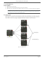
5.1 MENU PAGES
Operating the return key opens the first page of the menu, the content of which depends on the current access level and on the number of options enabled.
The description below assumes ‘Configuration’ level access.
Menu
Comms
Config
Access
Alarms
HA031414
Issue 1 Apr 13
Section 5.1.1
Section 5.1.2
Section 5.1.3
Section 5.1.4
Page 19
EPACK CONTROLLER: USER GUIDE
5.1.1 Comms menu
This allows the following communications parameters to be viewed or configured:
Comms
IP: Fixed
111.112.113.1
Mask:
255.255.255.0
Edit
IPMode
Fixed
Select ‘Fixed’ or DHCP
Menu
Comms
IPMode
IP address
SubNetMask
Edit
Edit
SubNetMask
Menu
Link Speed
IP
address
111.112.113.1
Enter IP address
255.255.255.0
Enter SubNet mask
Edit
Link
Speed
AutoNego
Select from:
‘AutoNego’,
100Mb, 100 Mb Half duplex,
10 Mb, 10Mb Half duplex.
Figure 5.1.1 Comms menu
Comms
IP Mode
IP Address
SubNetMask
Link Speed
Displays (read only) the current IP and Subnet mask addresses.
Allows the user to select ‘Fixed’ or ‘DHCP’ as the IP address source. If ‘Fixed’ is selected,
then the Address and Subnet Mask can be edited in the following fields. It must be ensured that the address is unique to the network. If DHCP is selected, the IP Address
and SubNetMask parameters described below do not appear. DHCP will be successful
only if there is a suitable DHCP server on the network to which the unit is connected.
Appears only if ‘Fixed’ is selected as IP Mode (above). Allows the user to edit the current IP address.
Example: To set an IP address of 111.112.113.1, use the up and down arrow pushbuttons to set the first section of the address to 111. Use the enter key, and then the up
and down pushbuttons to set the second section to 112. Use the enter key, and then
the up and down pushbuttons to set the third section to 113. Use the enter key, and
then the up and down pushbuttons to set the fourth section to 1 (not 01 or 001). Use
the Enter key to quit Edit mode. If any section is already as required, it can be skipped
by using the Enter key.
Set the subNet mask as described above for the IP address.
Select the required link type and speed.
Note... For details about subnet masks, see section 7.1.3 (iTools wiring).
Page 20
HA031414
Issue 1 Apr 13
EPACK CONTROLLER: USER GUIDE
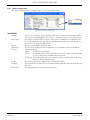
5.1.2 Config menu
This menu allows a number of network and firing output parameters to be set up, as well as Analogue input
and IP mode types
Edit
Enter nominal values
VLine
Nominal
230.
Edit
Edit
I
Nominal
Mode
16.0
Menu
BurstVar
VLine Nomin.
I Nominal
Mode
Soft Start
Select firing
mode
Edit
Soft
Start
Menu
Soft Stop
Type
IPMode
Off
Select number of
1/2 cycles
Off
Select number of
1/2 cycles
Edit
Soft
Stop
Edit
Edit
Type
IP Mode
0-10V
Fixed
Select analogue input type
Select IP Mode
Figure 5.1.2 Config menu
VLine Nominal
I Nominal
Mode
Soft Start
Soft Stop
Type
IP Mode
HA031414
Issue 1 Apr 13
Line voltage nominal value (Line to neutral)
Nominal current supplied to the load
Firing Mode. Allows the firing mode to be selected as Burts Var, Burst Fix, Logic, Phase
Angle (PA) or Intelligent half cycle (IHC). See section 6.9 for more details.
For Burst Firing only, this is the soft start duration, in supply voltage 1/2 cycles, applying
a phase angle ramp at the beginning of each on period. See section 6.9 for more details.
In Burst Firing, the soft stop duration, in supply voltage 1/2 cycles, applying a phase angle ramp at the end of each on period. See section 6.9 for more details.
Select the Analogue Input type as 0 to 10V, 1 to 5 V, 2 to 10V, 0 to 5V, 0 to 20mA,4 to
20mA.
Fixed or DHCP.
Page 21
EPACK CONTROLLER: USER GUIDE
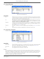
5.1.3 Access menu
Allows access to the Operator, Engineer, Configuration and Quick Code menus and allows passwords to be
set up. Alarms can also be viewed in this menu.
Edit
Edit
Goto
Pass
Code
Config
Select access
level required
3
Select correct
pass code for
selected access level
2
Edit Config
level code
1
Edit Engineer
level code
Edit
Config
Code
Menu
Goto
Config Code
Engineer Co.
Quick Code
Edit
Engineer
Code
Edit
Quick
Code
Menu
Alarms
4
Edit Quick code
accessl code
Alarms
Global Ack
Calib Err
Miss Mains
Thyr SC
See section 5.1.4
Figure 5.1.3 Access menu
Goto
Pass Code
Config Code
Engineer Code
Quick Code
Alarms
Allows access level to be selected.
Allows the user to enter the code for the access level required.
Allows the user to edit the Configuration access level code
Allows the user to edit the Engineer access level code
Allows the user to edit the Quik code access code
Any active alarms appear, and details can be found by selecting the relevant alarm and
using the Enter push button (Section 5.1.4).
Note...The default access codes are Operator = 0; Engineer = 1, Config = 2, Quickcode = 3.
Page 22
HA031414
Issue 1 Apr 13
EPACK CONTROLLER: USER GUIDE
5.1.3 ACCESS MENU (Cont.)
ACCESS TO MENUS
1. Open the Access menu item.
2. Open the Goto menu item and select the access level required.
3. Enter the access code for the level required. If this access code is correct the relevant menu appears.
Note... The above applies only when the user attempts to access a higher level than that current. If
accessing a lower level, the user needs only to open the Goto item and select the required level.
After doing this, the instrument will probably restart.
5.1.4 Alarms menu
Allows the user to view Global acknowledgement enable status, and calibration error (if any). Any active
alarms appear, and details can be found by selecting the relevant alarm and using the Enter push button.
Active alarms can be acknowledged, if applicable, by a further operation of the Enter button.
Param
Global
Ack
Yes
ACK?
Param
Calib
Error
1
Alarms
Global Ack
Calib Error
Miss Mains
Thyr SC
Use up/down arrows to
scroll through alarm list
Use Enter button to
acknowledge alarms
Param
Miss Mains
P1Latched
ACK?
Use Page (Menu) button to
return to the Alarms top level
Param
Thyr SC
P1Latched
ACK?
Figure 5.1.4 Alarms menu
HA031414
Issue 1 Apr 13
Page 23
EPACK CONTROLLER: USER GUIDE
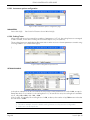
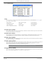
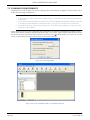
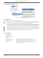
6 CONFIGURATION USING ITOOLS
6.1 INTRODUCTION
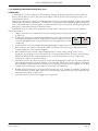
Note: Section 6 contains descriptions of all the menus which can appear. If an option or a feature is
not fitted and/or enabled, then it does not appear in the top level menu.
Section 7 details how to connect using iTools and gives details of the features available from this instrument.
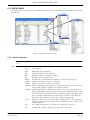
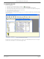
6.2 OVERVIEW
The configuration of the unit is divided into a number of separate areas as follows:
Access . . . . . . . . . . . . Section 6.3
Alarm . . . . . . . . . . . . . Section 6.4
Comms. . . . . . . . . . . . Section 6.5
Control . . . . . . . . . . . . Section 6.6
Energy . . . . . . . . . . . . Section 6.7
Fault Detection . . . . . Section 6.8
Firing o/p. . . . . . . . . . Section 6.9
Instrument . . . . . . . . . Section 6.10
I/O. . . . . . . . . . . . . . . . Section 6.11
IP Monitor . . . . . . . . . Section 6.12
Lgc2 . . . . . . . . . . . . . . Section 6.13
Lgc8 . . . . . . . . . . . . . . Section 6.14
Math2. . . . . . . . . . . . . Section 6.15
Modulator . . . . . . . . . Section 6.16
Network . . . . . . . . . . . Section 6.17
QCode . . . . . . . . . . . . Section 6.18
Setpoint provider. . . Section 6.19
User values . . . . . . . . Section 6.20
Diagnostics . . . . . . . . Section 6.21
iTools tree
Notes:
1. Current rating, limitation, transfer control, power control, energy counter and the graphical wiring
editor (GWE) are chargeable options. iTools secure can be used to upgrade units.
2 32A unit are set on 16A and 63A unit are on 40A by default.
Page 24
HA031414
Issue 1 Apr 13
EPACK CONTROLLER: USER GUIDE
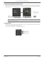
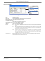
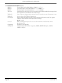
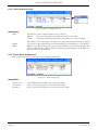
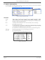
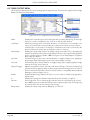
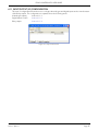
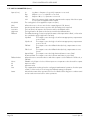
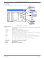
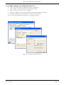
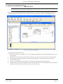
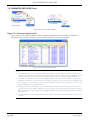
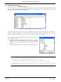
6.3 ACCESS MENU
Figure 6.3 iTools Access menu
Goto
Select access level
Passcode
Select relevant pass code for the access level required.
EngineerPasscode Passcode for Engineer level access
ConfigurationPasscode
Passcode for Configuration level access
QuickCodePasscode Access code for Quickcode menu
UPGPass
PassCode for upgrading device
Keylock
None No restriction. All parameters at the current access level may be viewed and edited.
All
All editing and navigation is prevented. All keys are locked so it is not possible
to ‘undo’ this action from the Operator interface. Once ‘All’ is selected, the keyboard can be released only via iTools.
Edit
Parameter editing is possible only in Configuration level; parameters are Read
Only in other levels. In the Operator or Engineer level menus, the ‘Back’ key is
still active allowing access to the ‘Goto’ menu so that the access level may be
changed if the relevant Pass code is known.
Clear memory
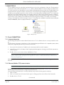
When available and set to ‘yes’, the device clears all configuration data, performs a
cold-start and enters the Quickcode mode.
HA031414
Issue 1 Apr 13
Page 25
EPACK CONTROLLER: USER GUIDE
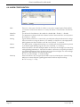
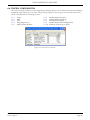
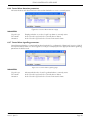
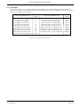
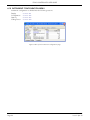
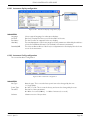
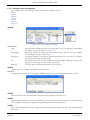
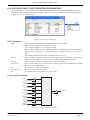
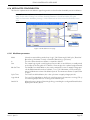
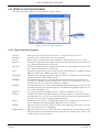
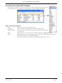
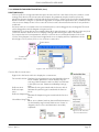
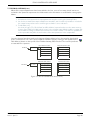
6.4 ALARM CONFIGURATION
Figure 6.4 Alarm configuration
Main
AlarmDis
AlmDet
AlmSig
AlmLat
AlmAck
AlmStop
Page 26
'ExternIn' is the input of this block. When connected to digital input 2 (DI2) and DI2
connected to a fuse blown detection contact, this alarm is considerd as a ‘fuse blown’
alarm
This allows the listed alarm to be enabled or disabled. 0 = Enable; 1 = Disable
This parameter indicates whether the alarms has been detected and is currently active.
0 = Inactive; 1 = Active
Signals that the alarm has occurred and is possibly latched by the Alarm Latch settings.
If the user wishes to assign an alarm to, for example, a relay then it is the appropriate
AlmSig parameter that should be wired. 0 = Not Latched; 1 = Latched.
The alarm can be configured as latching or non-latching, the latched state being shown
in the Alarm Signal (AlmSig) register. 0 = Non-Latching; 1 = Latching.
Allows the alarm to be acknowledged. When an alarm is acknowledged, its related signalling (AlmSig) parameter is cleared. If the alarm is still active (as shown by the detection (AlmDet) parameter) then the alarm cannot be acknowledged. The acknowledge
parameters automatically clear after being written.
0 = Do not acknowledge; 1 = Acknowledge
Allows the alarm to be configured such that it stops the related power channel firing.
AlmStop is activated by the signalling parameters and thus may be latching.
0 = Do not stop; 1 = Stop.
HA031414
Issue 1 Apr 13
EPACK CONTROLLER: USER GUIDE
6.5 COMMUNICATIONS CONFIGURATION
The communications menu allows the user to view, and in some cases, to edit communications parameters
associated with the communications option.
Figure 6.5b iTools comms page
Host name
SRV name
IP Mode
IP Status
IP
cSubnetMask
cDefault Gateway
Pref Master
Address
IP address
Subnet Mask
Default Gateway
HA031414
Issue 1 Apr 13
The name of the device on the link-local network.
For convenience, the device can declare itself on the pseudo-domain .local. If the hostname of the device is changed, it must be ensured that the name is unique on the network. In this is not the case, the instrument will transparently try to find another unique
name automatically.
The default value is related to the MAC address of the device and thus should already
be unique.
MBUS name. The name of the device, as shown by iTools
The IP configuration mode of the instrument.
0: Static. The IP parameters are taken from the parameter IPaddr, SubNetMark and
NetGateway.
1: DHCP.The IP address of the instrument is automatically assigned by an external
DHCP server. If the instrument fails to acquire an IP address, the auto IP mechanism assigns an IP to the instrument in the range 169.254.xxx.xxx with subnet
mask 255.255.0.0.
This (hidden) parameter describes the current status of the IP address of the instrument.
This is the current IP address of the device which may be different from the configured
IP address.
The current subnet mask associated with ‘IP’ above.
The current default gateway associated with ‘IP’ above.
The IP address of the preferred host.
On a network of instruments this address is used to specify a particular instrument. Each
instrument on a network must be set to a unique address, the available address range
depending upon the network protocol. (For Modbus/TCP, this is the modbus address
of the device (255 by default).)
The configured IP address of the device
The subnet mask associated with ‘IP address’ above.
The default gateway associated with ‘IP address’ above.
Page 27
EPACK CONTROLLER: USER GUIDE
6.5 COMMUNICATIONS MENU (Cont.)
MAC12
MAC34
MAC56
Timeout
Fallback1
Fallback2
En Timeout
Protocol
IO gateway
Link Speed
Page 28
First two Bytes of the MAC Address 11-22-33-44-55-66
Second two Bytes of the MAC Address 11-22- 33-44-55-66
Third two Bytes of the MAC Address 11-22-33-44- 55-66
Comms timeout value in ms. If no usercomms request arrives twithin the time specified
in this parameter, the Fallback values will change.
Set to 1 when a communication timeout has not occured; set to zero if a timeout occurs.
Inverse value of the Fallback1 parameter.
If set to ON (1), the timeout of the comms requests will be monitored. The outputs
Fallback1 and Fallback2 will be adjusted accordingly.
0 =Off. 1= On
Main communication protocol to access the instrument over ethernet comms.
0 = Modbus TCP
IP address of IO gateway.
Select a link speed from Auto negotiate, 100MB, 100MB half duplex, 10 MB or
10MB 1/2 duplex.
HA031414
Issue 1 Apr 13
EPACK CONTROLLER: USER GUIDE
6.6 CONTROL CONFIGURATION
The control menu provides the control algorithm to perform power control and transfer, threshold limiting
and phase angle reduction (in the case of burst firing). Figure 6.6, below, gives an overview of the menu,
which is described in the following sections:
6.6.1
6.6.2
6.6.3
6.6.4
6.6.5
Setup
Main
Limit
Diag (Diagnostics)
AlmDis (Alarm disable)
6.6.6
6.6.7
6.6.8
6.6.9
6.6.10
AlmDet (Alarm detection
AlmSig (Alarm Signalling)
AlmLat (larm latching)
AlmAck (Alarm Acknowledgement)
AlmStop (Stop firing on alarm)
Figure 6.6 Control menu overview
HA031414
Issue 1 Apr 13
Page 29
EPACK CONTROLLER: USER GUIDE
6.6.1 Control setup menu
This contains parameters for setting the type of control to be performed.
Figure 6.6.1 Control setup page
PARAMETERS
Standby
Nominal PV
En Limit
Transfer En
FF Type
FF Gain
FF Offset
Bleed Scale
Page 30
If Yes (1), the controller enters Standby mode and zero % power is demanded. When
removed from Standby (0) the unit returns to operating mode in a controlled manner.
Normally the nominal value for each control type. For example, for feedback mode =
V2, Vsq should be wired to the Main PV, and Nominal PV set to the nominal value expected for V2 (usually VLoadNominal2).
Used to enable/disable threshold limit.
Select Transfer Enable (Proportional limit) as ‘Yes’ (enabled) or ‘No’ (not enabled).
Feedforward Type.
Off (0).
Feedforward is disabled
Trim (1).
Feedforward value is the dominant element of the output. Trimmed by the
control loop based on the Main PV and setpoint.
FFOnly (2). The feedforward value is the output from the controller. Open loop control
may be configured by this means.
The entered gain value is applied to the Feedforward input.
The entered value is applied to the Feedforward input after the Gain value has been applied to it.
Internal parameter for use by service personnel
HA031414
Issue 1 Apr 13
EPACK CONTROLLER: USER GUIDE
6.6.2 Control Main menu
This menu contains all the parameters associated with the Main control loop.
Figure 6.6.2 Control ‘Main’ menu
PARAMETERS
PV
SP
Trans PV
Trans SP
TI
Displays the main Controller Process Variable (PV). Wired to the measurement which it
is to be controlled. For example, to perform V2 control. Vsq should be wired to this (PV)
parameter and Nominal PV configured appropriately.
The Setpoint to control at, as a percentage of Nominal PV (the upper range of the loop
in engineering units). For example, if Vsq = 193600, and SP is set to 20%, the controller
attempts to regulate at 193600 x 20/100 = 38720.
Transfer PV. This is the PV measurement for transfer. For example, if a V2 to I2 transfer
is required, the Vsq should be wired to MainPV and Isq to TransferPV. Appears only if
Trans Enable (section 6.6.1) is set to ‘Yes’.
The span of operation for transfer. Appears only if Trans Enable (section 6.6.1) is set to
‘Yes’.
Allows the user to define an integral time for the main PI control loop.
6.6.3 Control limit configuration
This area configures parameters relating to the limit control loop.
Figure 6.6.3 Control limit menu
PARAMETERS
PV1 to PV3
SP1 to SP3
TI
Threshold value for limit loops 1 to 3 respectively. This is the value to perform threshold
limit control. ‘Limit Enable’ must be set to ‘Yes’ in the Setup menu (section 6.6.1).
The setpoint for limit loops 1 to 3 respectively.
The integration time for the limit PI control loop.
Example:
If I2 threshold limiting is required, Isq is wired to PV1, and the required threshold value is entered at SP1. In
phase angle configuration, the phase angle is reduced to achieve the limit setpoint; in burst firing, the unit
continues to fire in bursts, but these bursts are of phase angle in order to achieve the limit setpoint. The
modulation continues to attempt to reach the main setpoint.
Also known as phase angle reduction burst firing.
HA031414
Issue 1 Apr 13
Page 31
EPACK CONTROLLER: USER GUIDE
6.6.4 Control diagnostic menu
Figure 6.6.4b iTools diagnostic menu
PARAMETERS
Status
Output
PAOP
Indicates the current operating state of the controller:
Main PV
The control strategy is using Main PV as the control input
Transfr
The transfer input us being used as the input to the control strategy.
Limit1(2)(3) Control limiting is currently active using limit PV1(2)(3) and limit SP 1(2)(3).
The current output demand in percent. Normally wired to Modulator.In or FiringOP.In
Applies only to Burst Firing control modes. If this parameter is wired to Firing.limitIn, the
power module will deliver bursts of phase angle firing depending both on the Main Setpoint and on the Limit Setpoint.
6.6.5 Control Alarm disable menu
Allows each alarm of the control block to be disabled, individually.
Figure 6.6.5 Alarm disable page
PARAMETERS
Closed Loop
PV Transfer
Limitation
Page 32
Select Enable (0) or Disable (1) for loop break alarm.
As for Closed Loop, but for the ‘Transfer active’ alarm.
As for Closed Loop, but for the ‘Control limit active’ alarm.
HA031414
Issue 1 Apr 13
EPACK CONTROLLER: USER GUIDE
6.6.6 Control Alarm detection parameters
Indicates whether each alarm has been detected and whether or not it is currently active.
Figure 6.6.6 Control Alarm detection page
PARAMETERS
Closed Loop
PV Transfer
Limitation
Displays whether or not the closed loop alarm is currently active.
As for Closed Loop, but for the ‘Transfer Active’ alarm.
As for Closed Loop, but for the ‘Control limit active’ alarm.
6.6.7 Control Alarm signalling parameters
Signals that an alarm has occurred and has been latched (if so configured in ‘Alarm Latch’ (section 6.6.8). If
it is required that an alarm is to be assigned to a relay (for example), then the appropriate alarm signalling
parameter should be used.
Figure 6.6.7 Control Alarm Signalling page
PARAMETERS
Closed Loop
PV Transfer
Limitation
HA031414
Issue 1 Apr 13
Indicates whether the closed loop break alarm is currently active.
As for Closed Loop, but for the ‘Transfer Active’ alarm.
As for Closed Loop, but for the ‘Control limit active’ alarm.
Page 33
EPACK CONTROLLER: USER GUIDE
6.6.8 Control Alarm Latch parameters
Allows each alarm to be configured as latching or not latching.
Fig 6.6.8 Control Alarm latching page
PARAMETERS
Closed Loop
PV Transfer
Limitation
Set the latching status of the alarm.
As for Closed Loop, but for the ‘Transfer Active’ alarm.
As for Closed Loop, but for the ‘Control limit active’ alarm.
6.6.9 Control Alarm Acknowledgement parameters
This menu allows individual alarms to be acknowledged. On acknowledgement, the related Signalling
parameter is cleared. The Acknowledge parameters automatically clear after being written.
If the alarm is still active (as shown by the Alarm Detection display) it cannot be acknowledged.
Figure 6.6.9 Control Alarm Acknowledge page
Closed Loop
PV Transfer
Limitation
Page 34
Displays whether the closed loop alarm has been acknowledged or not.
As for Closed Loop, but for the ‘Transfer Active’ alarm.
As for Closed Loop, but for the ‘Control limit active’ alarm.
HA031414
Issue 1 Apr 13
EPACK CONTROLLER: USER GUIDE
6.6.10 Control Alarm Stop parameters
Allows individual channels to be configured such that it will stop the associated power channel from firing
whilst the alarm is active. This feature is activated by the signalling parameters, so the alarm stop may be
latching.
Figure 6.6.10b iTools Control Alarm Stop page
PARAMETERS
Closed Loop
PV Transfer
Limitation
HA031414
Issue 1 Apr 13
Shows whether the closed loop alarm has been configured to disable firing or not.
As for Closed Loop, but for the ‘Transfer Active’ alarm.
As for Closed Loop, but for the ‘Control limit active’ alarm.
Page 35
EPACK CONTROLLER: USER GUIDE
6.7 ENERGY CONFIGURATION
Provides a number of energy counters to totalise consumed energy. The power consumed can be displayed
in one of number of units, ranging from W to GW.
Figure 6.7 Energy configuration page
PARAMETERS
UsrUnit
Input
Reset
Hold
UsrEnergy
Autoscale
Allows a scaling units value to be entered for the energy display. Selectable as ‘1Wh’,
‘10Wh’, ‘100Wh’, ‘1kWh’, ‘10kWh’, ‘100kWh’, ‘1MWh’, ‘10MWh’, ‘100MWh’ or ‘1GWh’.
Shows the instantaneous power input from the measuring source. Normally wired to
the Meas.P output of the Network block.
1 = Energy counter output goes to zero and immediately starts accumulating.
0 = Energy counter not reset.
1 = Hold output value. This freezes the output value for the block at the current value.
The input continues to be totalised, so when the Hold input returns to 0, the output value is instantaneously updated to the new current value.
0 = output value is not held, and represents the current accumulated Energy value.
Shows the current value for the selected Energy Counter block.
No = Use UsrUnit setting.
Yes = Autoscale power value display (table 6.7, below).
Power range (Watt-hours)
0 to
65,535 to
65,535,000 to
655,350,000 to
6,553,500,000 to
65,535,000,000 to
655,350,000,000 to
6,553,500,000,000
65535
65,535,000
655,350,000
6,553,500,000
65,535,000,000
655,350,000,000
6,553,500,000,000
upwards
Scaler value
1
1k
10k
100k
1M
10M
100M
1G
Table 6.7 Scaler values
Page 36
HA031414
Issue 1 Apr 13
EPACK CONTROLLER: USER GUIDE
6.7.1 Resolution
The resolution of the stored energy value varies according to the totalised value, as shown in table 6.7.1
below. For example, for stored values between 33,554,432 watt-hours and 67,108,863 watt-hours, the value
increases in 4 watt-hour increments.
Power range (Watt-hours)
Resolution
(W-h)
0 to 16,777,215
16,777,216 to 33,554,431
33,554,432 to 67,108,863
67,108,864 to 134,217,727
134,217,728 to 268,435,455
268,435,456 to 536,870,911
536,870,912 to 1,073,741,823
1,073,741,824 to 2,147,483,647
2,147,483,648 to 4,294,967,295
4,294,967,296 to 8,589,934,591
8,589,934,592 to 17,179,869,183
1
2
4
8
16
32
64
128
256
512
1024
Power range (Watt-hours)
Resolution
(W-h)
17,179,869,184 to 34,359,738,367
34,359,738,368 to 68,719,476,736
68,719,476,736 to 137,438,953,471
137,438,953,472 to 274,877,906,943
274,877,906,944 to 549,755,813,887
549,755,813,888 to 1,099,511,627,776
1,099,511,627,776 to 2,199,023,255,551
2,199,023,255,552 to 4,398,046,511,103
4,398,046,511,104 to 8,796,093,022,207
8,796,093,022,208 to 17,592,186,044,415
2048
4096
8192
16384
32768
65536
131072
262144
524288
1048576
Table 6.7.1 Energy counter resolution
HA031414
Issue 1 Apr 13
Page 37
EPACK CONTROLLER: USER GUIDE
6.8 FAULT DETECTION MENU
This manages Alarm logging and provides an interface for the General Alarm Acknowledgement
Figure 6.8 Fault detection menu page
PARAMETERS
Global Ack
Any Alarm
Network Alarm
Global Disable
StratStatus
Alarm Status 1(2)
Performs a global acknowledgement of alarms. Latched alarms are cleared if their trigger sources are no longer in an alarm state.
‘Active’ indicates that there is one or more System, Process or ‘Chop Off’ alarm active. If
the relevant alarms are enabled, System alarms and Chop Off alarms always cause the
power module to stop firing. Process alarms can also be configured to prevent firing in
‘Alarm stop’.
Indicates that a process alarm has occurred in the power network.
Allows the user to disable/enable all alarms.
A coded status word giving strategy information as shown in table 6.8a
Two 16-bit words containing alarm status information as shown in tables 6.8b and 6.8c.
Bit
0
1
2
3
4
5
6
7
8
9
10
11
12
13
14
15
Value
1
2
4
8
16
32
64
128
256
512
1024
2048
4096
8192
16384
32768
Description
Network not firing
Network not synchronising
Reserved
Reserved
Reserved
Reserved
Reserved
Reserved
Strategy in standby mode
Strategy in Telemetry mode
Reserved
Reserved
Reserved
Reserved
Reserved
Reserved
Table 6.8a Strategy status
Page 38
HA031414
Issue 1 Apr 13
EPACK CONTROLLER: USER GUIDE
6.8 FAULT DETECTION MENU (Cont.)
Bit
0
1
2
3
4
5
6
7
8
9
10
11
12
13
14
15
Value
1
2
4
8
16
32
64
128
256
512
1024
2048
4096
8192
16384
32768
Description
Missing mains
Thyristor short circuit
Over temp*
Network dips
Frequency fault
Total Load Failure
Chop off
Partial load failure
Partial load unbalance*
Over voltage
Under voltage
Pre temp*
Over current
Reserved
Analogue input over C
External input
Table 6.8b Alarm status word 1
Bit
0
1
2
3
4
5
6
7
8
9
10
11
12
13
14
15
Value
1
2
4
8
16
32
64
128
256
512
1024
2048
4096
8192
16384
32768
Description
Closed loop
Transfer active
Limit active
Reserved
Reserved
Reserved
Reserved
Reserved
Any bit in Global Status 0
Any bit in Global Status 1
Any bit in Global Status 2
Any bit in Global Status 3
Reserved
Reserved
Reserved
Reserved
Table 6.8c Alarm status word 2
* Note... These alarms not applicable at this release but are reserved for future development.
HA031414
Issue 1 Apr 13
Page 39
EPACK CONTROLLER: USER GUIDE
6.9 FIRING OUTPUT MENU
This forms the link between the control strategy and the physical load. This block also supplies Phase-Angle
Ramp (Soft start) and Safety Ramp.
Figure 6.9b iTools configuration firing output page
Mode
Load Type
Safety Ramp
Soft Start
Soft Stop
Delayed Trigger
Enable
In
PA Limit
Ramp Status
Page 40
Displays the current firing mode as Intelligent half cycle (IHC), Burst firing, Phase angle
firing or no mode. Configured in the ‘Modultr’, menu described below.
Allows the load type to be selected as ‘Resistive’ or ‘Transformer’. For Load type = Resistive, the load must be connected directly to the power module and only resistive
loads may be so connected. For Load Type = Transformer, the load is connected to the
power module via a transformer, and may be resistive or reactive.
Displays the safety ramp duration, in supply voltage cycles (0 to 255), to be applied at
startup. The ramp is either a phase angle ramp from zero to the requested target phase
angle or, for Burst Firing, from 0 to 100%. See figure 6.9.1a. Safety Ramp is not applicable to Half cycle Mode.
For Burst Firing only, this is the soft start duration, in supply voltage cycles, applying a
phase angle ramp at the beginning of each on period (figure 6.9.1b).
In Burst Firing, the soft stop duration, in supply voltage cycles, applying a phase angle
ramp at the end of each on period
Appears only if Mode = Burst, Soft Start = Off, and Load Type = TxFormer. Delayed Trigger specifies the triggering delay, in phase angle, when delivering power into a transformer load. Used to minimise inrush current. the value is configurable between 0 and
90 degrees inclusive (figure 6.9.1c).
Enables/disables firing. Must be wired to a non-zero value to enable firing (typically a
digital input).
Displays the input power demand value that the power module is to deliver.
Phase angle limit. This is a phase angle reduction factor used in Burst Firing. If lower
than 100% the power module will deliver a burst of phase angle firing. Used, typically,
to perform threshold current limiting in Burst Firing.
Displays the safety ramp status as ‘Ramping’ or ‘Finished’.
HA031414
Issue 1 Apr 13
EPACK CONTROLLER: USER GUIDE
6.9.1 Examples
Safety (Magnetisation) Ramp
(4 cycles)
Safety Ramp (10 cycles)
Output
voltage
Output
voltage
Line
supply
Line
supply
Resistive load
Delayed trigger angle
Inductive load
Figure 6.9.1a Safety ramp (burst firing) examples
Soft start = 2
Output
voltage
Line
supply
Figure 6.9.1b Soft start example
High current transient
Load voltage
Load current
Switch at zero volts
Figure 6.9.1c Delayed trigger definition
Note: Waveforms have been idealised for clarity.
HA031414
Issue 1 Apr 13
Page 41
EPACK CONTROLLER: USER GUIDE
6.10 INSTRUMENT CONFIGURATION MENU
Instrument configuration is divided into the following sections:
Display
Section 6.10.1
Configuration
Section 6.10.2
Options
Section 6.10.3
Scaling Factor Section 6.10.4
Figure 6.10 Top level instrument configuration page
Page 42
HA031414
Issue 1 Apr 13
EPACK CONTROLLER: USER GUIDE
6.10.1 Instrument display configuration
Figure 6.10.1 Instrument display configuration page
PARAMETERS
Language
Serial No
Dev Name
Label 0(1)
Param0(1)MB
Select required language for subsequent displays.
Read only. Displays the factory-set Serial number of the unit.
The device name as it appears at the user display.
The text that appears on the home page for the two parameters defined by the addresses listed in Param0 and Param1. User-definable 3 characters (maximum).
This is the modbus address of the first (second) parameter to be displayed in the home
screen of the instrument.
6.10.2 Instrument Config configuration
The current hardware configuration
Figure 6.10.2 Instrument configuration
PARAMETERS
Net Type
Power Type
Timer Res
Software
HA031414
Issue 1 Apr 13
Network type. This is set at the factory and cannot be changed by the user.
1 = Single phase
0 = 32A; 1 = 63A This is set at the factory and cannot be changed by the user.
Resolution of time parameters
0 = 10ths of seconds (100ms); 1 = 10ths of minutes (6 seconds)
Software version of the product.
Page 43
EPACK CONTROLLER: USER GUIDE
6.10.3 Instrument options configuration
Figure 6.10.3 Instrument options configuration page
PARAMETERS
Passcode1 (2)(3)
Pass Code for Features Secure Word 1(2)(3).
6.10.4 Scaling Factor
Allows scaling factors to be entered for a number of parameters. In iTools, the scaling factors are arranged
in ‘tabs’ of which, for the sake of clarity, this document depicts only one (SetProv).
These scaling factors are applied in modbus transactions when access to relevant parameters is made using
low range address (i.e. not the IEEE region)
]
Figure 6.10.4 Scaling factor top level menu.
SETPROV EXAMPLE
In the above example it can be seen that all the Set point provider parameters are scaled x100, except for
Ramp Rate which is not scaled (i.e. the scaling factor = 1). As can also be seen, the scaling factors available
are x1, x10, x100, x1000, ÷10, ÷100, ÷1000.
If the LocalSP, for example, has a scaling factor of x100, as above, then a value of say 5000 means in fact that
the real value is 50.00.
Notes:
1 The above example shows the default scaling formats set - they are User configurable.
2 Values are rounded up/down.
Page 44
HA031414
Issue 1 Apr 13
EPACK CONTROLLER: USER GUIDE
6.11 INPUT/OUTPUT (IO) CONFIGURATION
This area of configuration allows the user to configure the analogue and digital inputs and to view the status
of the Relay output. The configuration is separated into the following areas:
AI (analogue inputs)
Section 6.11.1
Digital inputs 1 and 2
Section 6.11.2
Relay output
Section 6.11.3.
Figure 6.11 Top level IO menu
HA031414
Issue 1 Apr 13
Page 45
EPACK CONTROLLER: USER GUIDE
6.11.1 Analogue input configuration
The configuration for the analogue input is divided into a number of areas:
Main,
AlmDis,
AlmDet,
AlmSig,
AlmLat,
AlmAck,
AlmStop.
AI MAIN
Figure 6.11.1b iTools analogue input page
PARAMETERS
Type
RangeHigh
RangeLow
PV
MeasVal
Allows the type of input to be set as one of: 0 to 10V, 1 to 5V, 2 to 10V, 0 to 5V, 0 to 20mA,
4 to 20mA. For pinout details, see figure 2.2.3.
High range of input for scaling from measurement units to process units. PV is clipped
to range high if input goes over range.
Low range of input for scaling from measurement units to process units. PV is clipped
to range low if input goes under range.
The scaled value in process units. Clipped to the Range High or Range Low value if the
signal goes over range or under range respectively.
The value at the instrument terminals in electrical units.
ALMDIS
Allows the user to enable or disable alarms individually
EXAMPLE
The figure below shows an iTools page for ALMDIS. Pages for the other ALM parameters are similar.
ALMDET
Indicates whether each individual alarm has been detected and is currently active.
ALMSIG
Signals that an alarm has occurred, and whether or not it is a latched. If the user wishes to assign an alarm
to for example a relay then the appropriate signalling parameter should be wired.
ALMLAT
Allows each individual alarm to be configured as latching, the latched state is shown in the alarm signalling
parameter
Page 46
HA031414
Issue 1 Apr 13
EPACK CONTROLLER: USER GUIDE
6.11.1 ANALOGUE INPUT CONFIGURATION (Cont)
ALMACK
Allows each individual alarm to be acknowledged. On an alarm being acknowledged the related signalling
parameter (ALMSIG) is cleared. If the alarm is still active as shown by the detection parameter (ALMDET) the
alarm may not be acknowledged. The acknowledge parameters automatically clear after being written.
ALMSTOP
Allows each individual alarm type to be configured to stop the power channel firing. ALMSTOP is activated
by the signalling parameter (ALMSIG) and may be latching or not according to the ALM LAT setting for the
alarm.
6.11.2 Digital input configuration
This allows the user to configure each of the digital inputs.
Figure 6.11.2b iTools Digital input configuration page
PARAMETERS
Type
Invert
PV
MeasVal
Select Logic Input (IP Volts) or IPContact. For pinout details, see figure 2.2.3.
Sets the inversion status to ‘No’ or ‘Yes’.
When set to ‘No’, there is no inversion (e.g. if MeasVal = 0 then PV = 0).
When set to ‘Yes’, an inversion takes place (e.g. if MeasVal = 0 then PV = 1)
The current state of the input, after any inversion has been applied.
For inputs, this shows the value measured at the instrument terminals, in electrical units.
6.11.3 Relay status
Figure 6.11.3b iTools relay status page
PARAMETERS
PV
Meas Val
This shows the status of the input to the relay as either ‘On’ (True) or ‘Off’ (False).
Shows the current state of the relay coil. 1 = energised; 0 = de-energised, where ‘energised’ is ‘off’ and ‘de-energised’ is ‘on’.
For pinout details, see figure 2.2.3.
HA031414
Issue 1 Apr 13
Page 47
EPACK CONTROLLER: USER GUIDE
6.12 IP MONITOR CONFIGURATION
This monitors a wired parameter and records its maximum value, minimum value and the cumulative time
that its value spends above a configurable threshold. An alarm can be set up to become active when the
time-over-threshold exceeds a further threshold.
Figure 6.12b iTools input monitor page (IPMon1)
PARAMETERS
In
Max
Min
Threshold
Days above
Time Above
Alarm Days
Alarm Time
Reset
Status
Page 48
The parameter to be monitored. Normally wired (using iTools) to a parameter, but a numeric entry can be made for testing purposes.
The maximum value reached by the parameter since last reset.
The minimum value reached by the parameter since last reset.
This value acts as a trigger for the ‘Time Above’ measurement.
Shows how many complete days the parameter value has spent above the Threshold
value (continuously or intermittently) since last reset. The ‘Time Above’ value should be
added to ‘Days Above’ in order to find the total time.
Shows how many hours, minutes and tenths of minutes that the parameter value has
spent above the threshold value (continuously or intermittently) since last reset, or since
the last complete day. (once the value exceeds 23:59.9, the ‘Days Above’ value is incremented and ‘Time Aboveis reset to 00:00.0.) The ‘Time Above’ value should be added
to ‘Days Above’ in order to find the total time.
Together with ‘Alarm Time’ this defines a ‘total time above threshold’ value, which, when
exceeded, sets the Alarm out parameter ‘On’.
See ‘Alarm Days’ above.
Resetting causes the Max. and Min. values to be set to the current value, sets the ‘Days
Above’ value to zero, and the ‘Time Above’ value to 00:00.0.
Shows the status of the input parameter as either ‘Good’ or ‘Bad’.
HA031414
Issue 1 Apr 13
EPACK CONTROLLER: USER GUIDE
6.13 LGC2 (TWO INPUT LOGIC OPERATOR) MENU
This logic operator block provides a number of two-input logic operations. The output is always a ‘Boolean’
(logic 0 or 1) no matter whether the inputs are analogue or digital. For analogue inputs, any value below 0.5
is deemed to be logic 0 (off). A value equal to or greater than 0.5 is treated as a logic 1 (on).
Either input can be ‘inverted’ as a part of the configuration (that is, a high input is treated as a low input and
vice-versa.)
Figure 6.13 Lgc2 page (Lgc2 1)
6.13.1 Lgc2 Parameters
Oper
In1
In2
Fallback type
Invert
Out
HA031414
Issue 1 Apr 13
Allows the user to select a logic operation for the block. The descriptions below assume
neither input is inverted. High = 1 or on; Low = 0 or off.
Off
No logic operation selected.
AND
Out is high if both inputs high, otherwise Out is low.
OR
Out is high if either or both inputs high, otherwise Out is low.
XOR
Output high if either (but not both) inputs high. Low if neither or both inputs are high.
Latch
If In2 low, Out latches next transition of In1. Value remains latched until
In2 goes low, when Out = In1 (see figure 6.13.1).
Equal
Out high if both inputs are equal, otherwise output is low.
Not Equal
Out is high if inputs are unequal. Out is low if inputs are equal.
Greater than Out is high if In1 value greater than In2 value, otherwise Out is low.
Less than
Out is high if In1 value less than In2 value, otherwise Out is low.
GreaterEqual Out is high if In1 value is equal to or greater than In2 value, otherwise Out
is low.
LessEqual
Out is high if In1 value is less than or equal to In2 value, otherwise Out is
low.
If wired, shows the value of In1; if not, allows the user to enter a value.
If wired, shows the value of In2; if not, allows the user to enter a value.
Allows a fallback type to be selected. This defines the output value and status displays
if the status of one or both inputs is ‘bad’.
FalseBad
Output value displays ‘False’ ; Status displays ‘Bad’
TrueBad
Output value displays ‘True’ ; Status displays ‘Bad’
FalseGood
Output value displays ‘False’ ; Status displays ‘Good’
TrueGood
Output value displays ‘True’ ; Status displays ‘Good.
Allows none, either or both inputs to be inverted.
Shows the current output value
Page 49
EPACK CONTROLLER: USER GUIDE
6.13.1 LGC2 PARAMETERS (Cont.)
Status
Hysteresis
Shows the status of the output (‘Good’ or ‘Bad’).
For comparison operators only (e.g. Greater than) this allows a hysteresis value to be
entered. For example, if the operator is ‘Greater than’ and hysteresis is H, then the output goes high when In1 exceeds In2, and remains high until In1 falls to a value less than
(In2 - H). Not applicable to the ‘Equal’ function.
Hysteresis
Figure 6.13.1 Hysteresis
In1
o/p latches first
transition of In1
o/p follows
In1
o/p latches first
transition of In1
o/p follows
In1
o/p latches first
transition of In1
In2
Out
When In2 goes low, Out follows the next positive or negative transition of In1 (points
‘X’) and latches at this value until In2 goes high. When In2 is high, Out follows In1.
Figure 6.13.2 Latch operation
Page 50
HA031414
Issue 1 Apr 13
EPACK CONTROLLER: USER GUIDE
6.14 LGC8 (EIGHT-INPUT LOGIC OPERATOR) CONFIGURATION
This allows between 2 and 8 inputs to be combined using an AND, OR or Exclusive OR (EXOR) logic function.
The inputs may be individually inverted, and the output can also be inverted, thus allowing the full range of
logic functions to be implemented.
Figure 6.14 Lgc8 configuration page
6.14.1 Parameters
Oper
Numin
InInvert
Out Invert
In1
In2 onwards
Out
Allows selection of AND, OR or Exclusive OR functions (or OFF).
AND = output is high only if all inputs are high
OR = output is high if any or all inputs are high
XOR = output is high if an odd number of inputs are high, and low if an even number of
inputs are high. Logically, a cascaded XOR function: (((((((In1 In 2) In 3) In 4)....
In 8)
Status =Bit to bit OR of the inputs concatenated into a word.
Set the number of inputs to between two and eight inclusive. This number defines how
many invert keys appear in ‘Invert’, and how many Input value pages appear.
Allows the user to invert individual inputs, as described below.
No = normal output; ‘Yes’ means that the output is inverted, allowing NAND and NOR
functions to be implemented.
The state (on or off) of the first input
The state of the remaining inputs
The Output value of the function (i.e. On or Off)
6.14.2 Inversion schematic
Input 1
Invert 1(x01)
Input 2
Invert 2 (x02)
Input 3
Invert 4 (x04)
Input 4
Invert 8 (x08)
Input 5
Invert 16 (x10)
Input 6
Invert 32 (x20)
Input 7
Invert 64 (x40)
Input 8
Invert 128 (x80)
Output
OutInvert
Figure 6.14.2 LGC8 inversion Schematic
HA031414
Issue 1 Apr 13
Page 51
EPACK CONTROLLER: USER GUIDE
6.14.3 Invert input decoding table
The inversion status can be encoded/decoded using the following table
Input
8 7 6 5 4 3 2 1 Hex Dec
N N N N N N N N 00 0
N N N N N N N 1 01 1
N N N N N N 2 N 02 2
N N N N N N 2 1 03 3
N N N N N 3 N N 04 4
N N N N N 3 N 1 05 5
N N N N N 3 2 N 06 6
N N N N N 3 2 1 07 7
N N N N 4 N N N 08 8
N N N N 4 N N 1 09 9
N N N N 4 N 2 N 0A 10
N N N N 4 N 2 1 0B 11
N N N N 4 3 N N 0C 12
N N N N 4 3 N 1 0D 13
N N N N 4 3 2 N 0E 14
N N N N 4 3 2 1 0F 15
N N N 5 N N N N 10 16
N N N 5 N N N 1 11 17
N N N 5 N N 2 N 12 18
N N N 5 N N 2 1 13 19
N N N 5 N 3 N N 14 20
N N N 5 N 3 N 1 15 21
N N N 5 N 3 2 N 16 22
N N N 5 N 3 2 1 17 23
N N N 5 4 N N N 18 24
N N N 5 4 N N 1 19 25
N N N 5 4 N 2 N 1A 26
N N N 5 4 N 2 1 1B 27
N N N 5 4 3 N N 1C 28
N N N 5 4 3 N 1 1D 29
N N N 5 4 3 2 N 1E 30
N N N 5 4 3 2 1 1F 31
N N 6 N N N N N 20 32
N N 6 N N N N 1 21 33
N N 6 N N N 2 N 22 34
N N 6 N N N 2 1 23 35
N N 6 N N 3 N N 24 36
N N 6 N N 3 N 1 25 37
N N 6 N N 3 2 N 26 38
N N 6 N N 3 2 1 27 39
N N 6 N 4 N N N 28 40
N N 6 N 4 N N 1 29 41
N N 6 N 4 N 2 N 2A 42
N N 6 N 4 N 2 1 2B 43
N N 6 N 4 3 N N 2C 44
N N 6 N 4 3 N 1 2D 45
N N 6 N 4 3 2 N 2E 46
N N 6 N 4 3 2 1 2F 47
N N 6 5 N N N N 30 48
N N 6 5 N N N 1 31 49
N N 6 5 N N 2 N 32 50
N N 6 5 N N 2 1 33 51
N N 6 5 N 3 N N 34 52
N N 6 5 N 3 N 1 35 53
N N 6 5 N 3 2 N 36 54
N N 6 5 N 3 2 1 37 55
N N 6 5 4 N N N 38 56
N N 6 5 4 N N 1 39 57
N N 6 5 4 N 2 N 3A 58
N N 6 5 4 N 2 1 3B 59
N N 6 5 4 3 N N 3C 60
N N 6 5 4 3 N 1 3D 61
N N 6 5 4 3 2 N 3E 62
N N 6 5 4 3 2 1 3F 63
Input
8 7 6 5 4 3 2 1 Hex Dec
N 7 N N N N N N 40 64
N 7 N N N N N 1 41 65
N 7 N N N N 2 N 42 66
N 7 N N N N 2 1 43 67
N 7 N N N 3 N N 44 68
N 7 N N N 3 N 1 45 69
N 7 N N N 3 2 N 46 70
N 7 N N N 3 2 1 47 71
N 7 N N 4 N N N 48 72
N 7 N N 4 N N 1 49 73
N 7 N N 4 N 2 N 4A 74
N 7 N N 4 N 2 1 4B 75
N 7 N N 4 3 N N 4C 76
N 7 N N 4 3 N 1 4D 77
N 7 N N 4 3 2 N 4E 78
N 7 N N 4 3 2 1 4F 79
N 7 N 5 N N N N 50 80
N 7 N 5 N N N 1 51 81
N 7 N 5 N N 2 N 52 82
N 7 N 5 N N 2 1 53 83
N 7 N 5 N 3 N N 54 84
N 7 N 5 N 3 N 1 55 85
N 7 N 5 N 3 2 N 56 86
N 7 N 5 N 3 2 1 57 87
N 7 N 5 4 N N N 58 88
N 7 N 5 4 N N 1 59 89
N 7 N 5 4 N 2 N 5A 90
N 7 N 5 4 N 2 1 5B 91
N 7 N 5 4 3 N N 5C 92
N 7 N 5 4 3 N 1 5D 93
N 7 N 5 4 3 2 N 5E 94
N 7 N 5 4 3 2 1 5F 95
N 7 6 N N N N N 60 96
N 7 6 N N N N 1 61 97
N 7 6 N N N 2 N 62 98
N 7 6 N N N 2 1 63 99
N 7 6 N N 3 N N 64 100
N 7 6 N N 3 N 1 65 101
N 7 6 N N 3 2 N 66 102
N 7 6 N N 3 2 1 67 103
N 7 6 N 4 N N N 68 104
N 7 6 N 4 N N 1 69 105
N 7 6 N 4 N 2 N 6A 106
N 7 6 N 4 N 2 1 6B 107
N 7 6 N 4 3 N N 6C 108
N 7 6 N 4 3 N 1 6D 109
N 7 6 N 4 3 2 N 6E 110
N 7 6 N 4 3 2 1 6F 111
N 7 6 5 N N N N 70 112
N 7 6 5 N N N 1 71 113
N 7 6 5 N N 2 N 72 114
N 7 6 5 N N 2 1 73 115
N 7 6 5 N 3 N N 74 116
N 7 6 5 N 3 N 1 75 117
N 7 6 5 N 3 2 N 76 118
N 7 6 5 N 3 2 1 77 119
N 7 6 5 4 N N N 78 120
N 7 6 5 4 N N 1 79 121
N 7 6 5 4 N 2 N 7A 122
N 7 6 5 4 N 2 1 7B 123
N 7 6 5 4 3 N N 7C 124
N 7 6 5 4 3 N 1 7D 125
N 7 6 5 4 3 2 N 7E 126
N 7 6 5 4 3 2 1 7F 127
Input
8 7 6 5 4 3 2 1 Hex Dec
8 N N N N N N N 80 128
8 N N N N N N 1 81 129
8 N N N N N 2 N 82 130
8 N N N N N 2 1 83 131
8 N N N N 3 N N 84 132
8 N N N N 3 N 1 85 133
8 N N N N 3 2 N 86 134
8 N N N N 3 2 1 87 135
8 N N N 4 N N N 88 136
8 N N N 4 N N 1 89 137
8 N N N 4 N 2 N 8A 138
8 N N N 4 N 2 1 8B 139
8 N N N 4 3 N N 8C 140
8 N N N 4 3 N 1 8D 141
8 N N N 4 3 2 N 8E 142
8 N N N 4 3 2 1 8F 143
8 N N 5 N N N N 90 144
8 N N 5 N N N 1 91 145
8 N N 5 N N 2 N 92 146
8 N N 5 N N 2 1 93 147
8 N N 5 N 3 N N 94 148
8 N N 5 N 3 N 1 95 149
8 N N 5 N 3 2 N 96 150
8 N N 5 N 3 2 1 97 151
8 N N 5 4 N N N 98 152
8 N N 5 4 N N 1 99 153
8 N N 5 4 N 2 N 9A 154
8 N N 5 4 N 2 1 9B 155
8 N N 5 4 3 N N 9C 156
8 N N 5 4 3 N 1 9D 157
8 N N 5 4 3 2 N 9E 158
8 N N 5 4 3 2 1 9F 159
8 N 6 N N N N N A0 160
8 N 6 N N N N 1 A1 161
8 N 6 N N N 2 N A2 162
8 N 6 N N N 2 1 A3 163
8 N 6 N N 3 N N A4 164
8 N 6 N N 3 N 1 A5 165
8 N 6 N N 3 2 N A6 166
8 N 6 N N 3 2 1 A7 167
8 N 6 N 4 N N N A8 168
8 N 6 N 4 N N 1 A9 169
8 N 6 N 4 N 2 N AA 170
8 N 6 N 4 N 2 1 AB 171
8 N 6 N 4 3 N N AC 172
8 N 6 N 4 3 N 1 AD 173
8 N 6 N 4 3 2 N AE 174
8 N 6 N 4 3 2 1 AF 175
8 N 6 5 N N N N B0 176
8 N 6 5 N N N 1 B1 177
8 N 6 5 N N 2 N B2 178
8 N 6 5 N N 2 1 B3 179
8 N 6 5 N 3 N N B4 180
8 N 6 5 N 3 N 1 B5 181
8 N 6 5 N 3 2 N B6 182
8 N 6 5 N 3 2 1 B7 183
8 N 6 5 4 N N N B8 184
8 N 6 5 4 N N 1 B9 185
8 N 6 5 4 N 2 N BA 186
8 N 6 5 4 N 2 1 BB 187
8 N 6 5 4 3 N N BC 188
8 N 6 5 4 3 N 1 BD 189
8 N 6 5 4 3 2 N BE 190
8 N 6 5 4 3 2 1 BF 191
Input
8 7 6 5 4 3 2 1 Hex Dec
8 7 N N N N N N C0 192
8 7 N N N N N 1 C1 193
8 7 N N N N 2 N C2 194
8 7 N N N N 2 1 C3 195
8 7 N N N 3 N N C4 196
8 7 N N N 3 N 1 C5 197
8 7 N N N 3 2 N C6 198
8 7 N N N 3 2 1 C7 199
8 7 N N 4 N N N C8 200
8 7 N N 4 N N 1 C9 201
8 7 N N 4 N 2 N CA 202
8 7 N N 4 N 2 1 CB 203
8 7 N N 4 3 N N CC 204
8 7 N N 4 3 N 1 CD 205
8 7 N N 4 3 2 N CE 206
8 7 N N 4 3 2 1 CF 207
8 7 N 5 N N N N D0 208
8 7 N 5 N N N 1 D1 209
8 7 N 5 N N 2 N D2 210
8 7 N 5 N N 2 1 D3 211
8 7 N 5 N 3 N N D4 212
8 7 N 5 N 3 N 1 D5 213
8 7 N 5 N 3 2 N D6 214
8 7 N 5 N 3 2 1 D7 215
8 7 N 5 4 N N N D8 216
8 7 N 5 4 N N 1 D9 217
8 7 N 5 4 N 2 N DA 218
8 7 N 5 4 N 2 1 DB 219
8 7 N 5 4 3 N N DC 220
8 7 N 5 4 3 N 1 DD 221
8 7 N 5 4 3 2 N DE 222
8 7 N 5 4 3 2 1 DF 223
8 7 6 N N N N N E0 224
8 7 6 N N N N 1 E1 225
8 7 6 N N N 2 N E2 226
8 7 6 N N N 2 1 E3 227
8 7 6 N N 3 N N E4 228
8 7 6 N N 3 N 1 E5 229
8 7 6 N N 3 2 N E6 230
8 7 6 N N 3 2 1 E7 231
8 7 6 N 4 N N N E8 232
8 7 6 N 4 N N 1 E9 233
8 7 6 N 4 N 2 N EA 234
8 7 6 N 4 N 2 1 EB 235
8 7 6 N 4 3 N N EC 236
8 7 6 N 4 3 N 1 ED 237
8 7 6 N 4 3 2 N EE 238
8 7 6 N 4 3 2 1 EF 239
8 7 6 5 N N N N F0 240
8 7 6 5 N N N 1 F1 241
8 7 6 5 N N 2 N F2 242
8 7 6 5 N N 2 1 F3 243
8 7 6 5 N 3 N N F4 244
8 7 6 5 N 3 N 1 F5 245
8 7 6 5 N 3 2 N F6 246
8 7 6 5 N 3 2 1 F7 247
8 7 6 5 4 N N N F8 248
8 7 6 5 4 N N 1 F9 249
8 7 6 5 4 N 2 N FA 250
8 7 6 5 4 N 2 1 FB 251
8 7 6 5 4 3 N N FC 252
8 7 6 5 4 3 N 1 FD 253
8 7 6 5 4 3 2 N FE 254
8 7 6 5 4 3 2 1 FF 255
Example: Decimal 146 means that inputs 8, 5 and 2 are inverted.
Page 52
HA031414
Issue 1 Apr 13
EPACK CONTROLLER: USER GUIDE
6.15 MATH2 MENU
This feature allows a range of two-input mathematical functions to be performed. The available functions are
listed below.
Figure 6.15 Maths2 configuration page
6.15.1 Math 2 Parameters
Note: For the sake of this description, ‘High’, ‘1’ and ‘True’ are synonymous, as are ‘Low’, ‘0’ and
‘False’.
Oper
HA031414
Issue 1 Apr 13
Defines the mathematical function to be applied to the inputs
None
No operation.
Add
Adds input one to input two.
Sub
Subtracts input two from input one.
Mul
Multiplies inputs one and two together.
Div
Divides input one by input two.
AbsDif
The difference in value between inputs one and two, ignoring sign.
SelMax
Output = the higher of inputs one and two.
SelMin
Output = the lower of inputs one and two.
HotSwap Input one appears as the output for as long as input one is ‘good’. If input one
status is bad, input two appears as the output instead.
SmpHld Sample and Hold. The output follows input one, for as long as input two is
high (sample). When input two goes low (hold), the output is held, at the value current when the output went low, until input two goes high again. Input
two is normally a digital value (low = 0 or high =1); when it is an analogue
value, then any positive non-zero value is interpreted as a high.
Power
Output = Input one raised to the power of input two (In1In2). For example if
input one has the value 4.2, and the value of input two is 3, then output = 4.23
= 74.09 (approx.).
Sqrt
The output is the square root of input one. Input two is not used.
Log
Log base 10: Output = {Log10 (In 1)}. Input two is not used.
Page 53
EPACK CONTROLLER: USER GUIDE
6.15 MATH2 PARAMETERS (Cont.)
Oper (Cont.)
In1(2) Mul
Units
Resolution
Low Limit
High Limit
Fallback
Fallback value
Select
In1
In2
Out
Status
Page 54
Ln
Exp
10_x
Sel1
Log base e: Output = {Logn (In1)}. Input two is not used.
Output = e(input one). Input two is not used.
Output = 10(input one). Input two is not used.
If the Select input is high, input two appears at the output; if the Select input
is low, input one appears at the output.
The scaling factor to be applied to input one (two).
Allows the user to choose units for the output (figure 6.15b, above).
Use the up and down arrows to position the decimal point as required.
The low limit for all inputs to the function and for the fallback value.
The high limit for all inputs to the function and for the fallback value.
The fallback strategy comes into play if the status of the input value is ‘Bad’, or if its value
lies outside the range (High limit- Low limit).
Clip Bad
The output is set to the high or low limit as appropriate; output status
is set to ‘Bad’.
Clip Good
The output is set to the high or low limit as appropriate; output status
is set to ‘Good’.
Fall Bad
The output is set to the fallback value (below); output status is set to
‘Bad’.
Fall Good
The output is set to the fallback value (below); output status is set to
‘Good’.
Upscale Bad
The output is set to the high limit and Status is set to ‘Bad’.
Downscale Bad The output is set to the low limit and Status is set to ‘Bad’.
Allows the user to enter the value to which the output is set for Fallback = Fall Good, or
Fall Bad.
Editable only if Oper = Select. Allows input one or input two to be selected for output.
Input one value
Input two value
The output value resulting from the configured mathematical operation. If either input
is ‘Bad’, or if the result is out of range, the fallback strategy is adopted.
Indicates the status of the operation as ‘Good’ or ‘Bad’. Used to flag error conditions and
can be used as an interlock for other operations.
HA031414
Issue 1 Apr 13
EPACK CONTROLLER: USER GUIDE
6.16 MODULATOR CONFIGURATION
This function implements the modulation type firing modes such as fixed and variable period modulation.
Note... For the sake of completeness, all Modulator parameters are shown in the figure below. Normally, for the sake of clarity, non-relevant (shaded) parameters should be hidden using the
‘Options>Parameter Availablity Settings...>Hide Parameters and Lists when Not Relevant’ menu
item.
Figure 6.16 Modulator menu page
6.16.1 Modulator parameters
Mode
In
Out
Min On Time
Cycle Time
Logic Mode
Switch PA
HA031414
Issue 1 Apr 13
Select the required firing mode from ‘Logic’, ‘PA’ (Phase angle) ‘Half cycle’, ‘BurstVar’
(Burst firing - minimum on time) or ‘BurstFix’ (Burst firing - cycle time).
This is the value that the modulator is required to deliver.
The output logic signal controlling the power module on and off times, normally wired
to the input of the firing block. For Mode = Phase angle, this is a phase angle demand.
For Variable Period Modulation, this sets the minimum on time in supply voltage periods. At 50% demand from the modulator, Ton = Toff = Minimum on time, and Cycle
time is 2 x Minimum on time = Modulation period. The minimum off time is equal to ‘Min
on time’.
For Fixed Period Modulation, this is the cycle time in supply voltage periods.
For Logic Firing Modulation, Half cycle sets firing stop to the next zero crossing; Full cycle sets firing stop at the zero crossing of the next full cycle.
Allows the user to impose Phase Angle firing, overriding the configured Burst Mode as
displayed in ‘Mode’, above.
Page 55
EPACK CONTROLLER: USER GUIDE
6.17 NETWORK CONFIGURATION
This identifies the type of electrical network to be controlled, and this, in turn defines how the network’s
electrical measurements are presented. The configuration is divided into a number of areas:
Meas,
Setup
AlmDis,
AlmDet,
AlmSig,
AlmLat,
AlmAck,
AlmStop.
Figure 6.17 Network configuration - top level
Page 56
HA031414
Issue 1 Apr 13
EPACK CONTROLLER: USER GUIDE
6.17.1 Network Meas Menu
Figure 6.17.1 Network Meas configuration page
PARAMETERS
This submenu presents power network measurements, according to the network type. All available
measurements are listed below, but which values actually appear depends on the network configuration.
Frequency
Vline
I
IsqBurst
Isq
V
VsqBurst
Vsq
P Burst
P
S
PF
Z
HSink Temp
HA031414
Issue 1 Apr 13
Displays the calculated frequency of the supply voltage of the power channel associated with this network.
Supply voltage measurement.
Load Irms measurement on primary power module. The time base measurement is the
main period in Phase Angle, and the modulation period in Burst Mode.
Average square value of load current in burst firing. The average Isq in burst firing, the
average is taken over the duration of the burst period. This is typically used for monitoring and alarming over the burst period.
Square value of load current in Burst Firing and over the main period in phase angle.
Load Vrms measurement. The time base measurement is the main period in phase angle, and the modulation period in burst mode.
Average square value of load voltage in burst firing taken over the duration of the burst
period. Typically used for monitoring and alarm strategies over the burst period.
Square value of load voltage in Burst Firing and on main period in Phase Angle Firing.
Typically used for V2 control.
Measurement of true power on the network. This is calculated over the modulation period in Burst Firing mode. Typically used for monitoring and alarm strategy.
True power measurement in Burst Firing and over the modulation period in Phase Angle firing. Typically used for true power control.
Apparent power measurement. For phase angle firing S=Vline x IRMS; for burst firing
S=VRMS x IRMS
Calculation of power factor. Defined as Power Factor = True Power / Apparent Power. In
phase angle this is PF=P/S; in burst firing PF = PBurst/S = Cos(Load)
Load impedance measurement on first power module, defined as:- Z=Vrms/Irms.
Measurement uses line current and load voltage
Reserved for future development.
Page 57
EPACK CONTROLLER: USER GUIDE
6.17.2 Network Setup configuration
This displays the setup of the network and associated functions.
Figure 6.17.2 Network setup menu page
PARAMETERS
NetType
The type of network to which the unit can be connected. This is set at the factory and
cannot be changed
VMaximum
Indicates the maximum voltage (physical rating) of the stack (500V)
Vline Nominal
Line voltage nominal value (Line to neutral)
IMaximum
Indicates the maximum current of the stack (16A, 25A, 40A, 63A). Further values (80A,
100A, 125A, 160A) are reserved for future development.
INominal
Nominal current supplied to the load (limited by IMaximum).
VLoadType
Defines the computation method for load voltage (Vload).
0: Vload = Vline as long as I > Ithreshold (internal definition)
1: Compute Vload using the formula V²load=P²/I².
VdipsThreshold
Voltage dips threshold. This is a percentage difference (relative to Vline Nominal) between 2 consecutive half cycles. Each half cycle voltage measurement is integrated and
at the end of each half cycle the last two voltage integrals are compared.
FreqDriftThold
The supply frequency is checked every half cycle, and if the percentage change between 1/2 cycles exceeds this threshold value, a Mains Frequency System Alarm is generated. The threshold may be set to a maximum of 5% to cater for the effects of heavily
inductive networks.
ChopOffThreshold The ‘Chop-off’ alarm becomes active if load current exceeds this threshold for more
than a pre-defined number of mains periods (Number Chop Off parameter). Threshold
values lie between 100% and 400% of the unit’s nominal current (INominal).
NumberChopOff
Definition of the number of mains periods in which Chop Off events can occur before
a Chop Off alarm is enabled. Only used with Chop Off Threshold .
OverVoltThreshold The threshold for detecting an over voltage condition as a percentage of VLineNominal. If Vline rises above the threshold an OverVolt alarm is set.
UnderVoltThreshold This is the threshold for detecting an under voltage condition as a percentage of
VLineNominal. If Vline falls below the threshold an UnderVolt alarm is set
Page 58
HA031414
Issue 1 Apr 13
EPACK CONTROLLER: USER GUIDE
6.17.2 NETWORK SETUP CONFIGURATION (Cont.)
PARAMETERS (Cont.)
Heatsink PreTemp
PLFAdjustReq
PLFAdjusted
PLFSensitivity
Zref
OverIThreshold
HeaterType
HA031414
Issue 1 Apr 13
Reserved for future development.
Partial load failure adjustment request. To make the Partial Load Failure (PLF) alarm operate correctly, the normal steady-state condition must be known to the instrument. This
is done by activating the PLF Adjust Req once the controlled process has achieved a
steady state condition. This causes a load impedance measurement to be made which
is used as a reference for detecting a partial load failure. If the load impedance measurement is successful PLFAdjusted (below) is set. The measurement fails if the load voltage (V) is below 30% of (VNominal) or the current (I) is below 30% of (INominal). The PLF
alarm becomes active as setup in ‘PLF Sensitivity’, below.
Partial load failure adjusted acknowledge. Indicates that the user requested a PLF adjustment and that the adjustment was successful.
Partial load failure sensitivity. This defines how sensitive the partial load failure detection
is to be as the ratio between the load impedance for a PLFadjusted load and the current
impedance measurement. For example for a load of N parallel, identical elements, if the
PLF Sensitivity (s) is set to 2, then a PLF alarm will occur if N/2, or more elements are broken (i.e. open circuit). If PLF Sensitivity is set to 3, then a PLF alarm occurs if N/3 or more
elements are broken. If (N/s) is non-integer, then the sensitivity is rounded up.
E.G. if N = 6 and s= 4, then the alarm is triggered if 2 or more elements are broken.
Reference load impedance, as measured when PLF adjust is requested.
The threshold for detecting an over current condition as a percentage of INominal. If I
is above the threshold a Mains Current Alarm occurs (DetoverCurrent).
Shows the type of heater used in the load as: ‘Resistive’, ‘SWIR’ (Short wave infra-red),
‘CSi’ (Silicon Carbide), ‘MoSi2’ (Molybdenum Disilicide).
Page 59
EPACK CONTROLLER: USER GUIDE
6.17.3 Network alarms
Figure 6.17.3 Network alarms page
ALMDIS
This menu allows individual network block alarms (listed below) to be enabled/disabled. Section 9 gives
more details of these alarms.
Missing Mains
Thyristor short circuit
Over temperature
Mains voltage (Network) dips
Mains frequency fault
Chop Off
Under voltage
Over voltage
Total load failure
Partial load failure
Pre Temperature
Over current
NETWORK ALMDET SUBMENU
As for ‘Alarm Disable’, above, but this Alarm detect submenu indicates whether any of the network alarms
has been detected and is currently active.
NETWORK ALMSIG SUBMENU
These displays show whether an alarm has occurred and also contains latching information. The relevant
AlarmSig parameter is used when wiring (to a relay for example). The alarm list is as given above.
NETWORK ALMLAT SUBMENU
As for ‘Alarm Disable’, above, but this Alarm Latch submenu allows each individual network block alarm to
be defined as latching or non-latching.
NETWORK ALMACK SUBMENU
As for ‘Alarm Disable’, above, but this Alarm Acknowledge submenu allows each individual network block
alarm to be acknowledged. Once acknowledged, the associated signalling parameter is cleared.
Acknowledge parameters automatically clear after being written.
Note... Alarms may not be acknowledged whilst the trigger source is still active.
NETWORK ALMSTOP SUBMENU
Allows each individual alarm type to be configured to stop the related power module from firing. Activated
by the related Signalling parameter. The alarm list is as given above.
Page 60
HA031414
Issue 1 Apr 13
EPACK CONTROLLER: USER GUIDE
6.18 QCODE
Quick code parameters, settable when in Quickcode configuration mode as well as here.
Figuire 6.18 Quick code parameters
6.18.1 Parameters
Firing
En_Limit
En_Transfer
Control
Heater
AI_Fct
AI_Type
DI2_Fct
XFmr
I_Nominal
V_Nominal
Finish
Refresh
HA031414
Issue 1 Apr 13
Select firing mode from IHC (Intelligent half cycle), Burst firing (fixed or variable), Logic
or Phase angle.
Enable or disable threshold limit.
Enable or disable transfer enable (Proportional limit).
Select ‘Power‘ or ‘Vsq’ (V2) as the control mode.
Select Resistive, Short wave infra red (SWIR), Silicon carbide (CSi) or Molybdenum disilicide (MoSi2) as the heating element type.
Select the Analogue Input function as ‘Setpoint’ or ‘Setpoint limit’.
Select the required Volt or mA range (as shown above) for the analogue input.
Select the funtion of Digital Input 2 as ‘None’, Alarm acknowledge (‘AlarmAck’), Select
remote setpoint (‘RemoteSelect’) or Fuse Blown (‘FuseBlown).
Select output as suitable for resistive loads or for transformer primary loads.
The nominal output currect expected to be drawn.
The nominal output voltage to be supplied.
Quit quick code.
Refresh quick code parameters.
Page 61
EPACK CONTROLLER: USER GUIDE
6.19 SETPROV CONFIGURATION MENU
The Setpoint provider supplies one local and one remote setpoint.
Figure 6.19 SetProv configuration page
6.19.1 Setpoint provider parameters
SPSelect
RemSelect
LocalSP
Remote1
Remote21
Limit
WorkingSP
RampRate
DisRamp
RateDone
SPTrack
SPUnits
HiRange
EngWorkingSP
Page 62
Allows the user to select between Remote or Local as the setpoint source.
Select Remote1 or Remote2 as the remote setpoint.
Allows entry of a setpoint value to be used when SPSelect (above) is set to ‘Local’.
The Remote setpoint value (normally wired from an analogue input) for use when SPSelect = Remote and RemSelect = Remote1.
The Remote setpoint value (normally wired from an analogue input) for use when SPSelect = Remote and RemSelect = Remote2.
Allows the target setpoint to be scaled such that ‘scaled target SP’ = (target SP x limit)/
100. Thus, when limit = 100, the setpoint is unscaled.
The active value being provided as a setpoint output. This might be the current target
setpoint or the rate-limited target setpoint.
This applies a rate limit to the working setpoint, until the target setpoint has been
achieved. The ‘RateDone’ parameter (below) is set to ‘No’ for the duration of the rate
limiting, then set to ‘Yes’ when rate limiting is complete.
This is an external control used to enable/disable ramp rate limiting and to write the target setpoint directly to the working setpoint. The ‘RateDone’ parameter (below) is set
to ‘Yes’ when DisRamp is ‘Yes’.
Set to ‘No’ if ramp rate limiting (above) is in operation. Otherwise set to ‘Yes’.
If enabled (‘Yes’) the local setpoint tracks the remote setpoints, so that if the setpoint is
subsequently set to ‘Local’, the local setpoint will be the same as the last known value of
the remote setpoint, thus ensuring a bumpless transfer.
Allows the user to select % or ‘Eng’ (Engineering units) as Setpoint units. If ‘Eng’ is selected, ‘HiRange’ and ‘Eng workingSP’ appear at the user interface.
Appears only if SP units set to ‘Eng’. This value is the high range of the setpoint used to
scale the setpoint into % of High Range.
Appears only if SP units set to ‘Eng’. This value is an indication of the working setpoint
in Engineering units. The parameter must not be used for control because control loops
accept setpoints only as % values.
HA031414
Issue 1 Apr 13
EPACK CONTROLLER: USER GUIDE
6.20 USER VALUE CONFIGURATION MENU
This provides storage for up to four user-defined constants. Typical uses are as a sources
for maths functions, or as storage for values written over the communications link.
Figure 6.20 Top level UseVal page
6.20.1 User Value parameters
Units
Resolution
High/Low Limit
Value
Status
HA031414
Issue 1 Apr 13
Allows the selection of User value units.
Set the number of decimal places for the User Value value.
Allows the user to set limits to prevent the user value from being set
out-of-bounds.
Allows the user to enter a value, or the value if wired to a suitable parameter.
If this parameter is wired, it can be used to force a Good or Bad status onto the User
Value for test purposes (e.g. fallback strategy).
If not wired, it reflects the status of the Value input if this input is wired.
Page 63
EPACK CONTROLLER: USER GUIDE
7 USING ITOOLS
iTools software running on a pc allows quick and easy access to the configuration of the unit. The parameters
used are the same as those described in section 6 above, with the addition of various diagnostic parameters.
iTools also gives the user the ability to create software wiring between function blocks, something that is not
possible from the operator interface. Such wiring is carried out using the Graphical wiring Editor feature.
In addition to the guidance given here, there are two on-line Help systems available within iTools: Parameter
help and iTools help. Parameter help is accessed by clicking on ‘Help’ in the toolbar (opens the complete
parameter help system), by right-clicking on a parameter and selecting ‘Parameter Help’ from the resulting
context menu, or by clicking on the Help menu and selecting ‘Device Help’. iTools help is accessed by
clicking on the Help menu, and selecting ‘Contents’. iTools help is also available in manual format under part
number HA028838, either as a physical manual or as a pdf file.
Tool bar icon for
parameter help
Help menu
Figure 7 Help access
7.1 iTools CONNECTION
7.1.1 Automatic detection
The following descriptions assume that the latest version iTools software as been correctly installed on the
pc.
For EPack units only (at time of publication), if the desktop/laptop and EPack are IP compatible (same subnet
mask) then, Plug & Play allows easy connection as follows.
1. Set correct IP mode and or IP address to the instrument and Personal Computer.
2.. Launch iTools, click on the button 'Add' a popup window appears showing you all EPack instruments
on the network.
3. Double click on one or more units to add them to iTools.
Note...'Eurotherm discovery' mechanism is based on 'Zero Configuration Networking' which is
generic name used to group protocosl together in order to create communication networks automatically (Plug & Play)
Alternatively, if there is a mix of EPack and other instruments on the network, the following procedure can
be used:
7.1.2 Ethernet (Modbus TCP) communications
Note: the following description is based on windows XP. Windows ‘Vista’ is similar.
It is first necessary to determine the IP address of the unit, as described under ‘Comms menu’ in section 6.5.
This can be done from either the Config or Quickcode menu.
Once the Ethernet link has been correctly installed, carry out the following actions at the pc:
1. Click on ‘Start’
2. Click on ‘Control Panel’. (If Control Panel opens in ‘Category View’ select ‘Classic View’ instead.)
3. Double-click on ‘iTools’.
(Continued)
Page 64
HA031414
Issue 1 Apr 13
EPACK CONTROLLER: USER GUIDE
7.1.2 ETHERNET (MODBUS TCP) COMMUNICATIONS (Cont.)
4. Click on the TCP/IP tab in the Registry settings configuration.
5. Click on Add... The ‘New TCP/IP Port’ dialogue box opens.
6. Type-in a name for the port, then click Add...
7. Type the IP address of the unit in the ‘Edit Host’ box which appears. Click OK.
8. Check the details in the ‘New TCP/IP Port’ box, then click on ‘OK’.
Click on ‘OK’ in the ‘Registry settings’ box to confirm the new port.
)
Figure 7.1.2a Adding a new Ethernet port
HA031414
Issue 1 Apr 13
Page 65
EPACK CONTROLLER: USER GUIDE
7.1.2 ETHERNET (TCP/IP) COMMUNICATIONS (Cont.)
To check that the pc can now communicate with the instrument, Click ‘Start’. ‘All Programs’, ‘Accessories’,
‘Command Prompt’
when the Command Prompt box appears, type in : Ping<Space>IP1.IP2.IP3.IP4<Enter> (where IP1 to IP4 are
the IP address of the instrument).
If the Ethernet link to the instrument is operating correctly, the ‘successful’ reply arrives. Otherwise, the
‘failed’ reply arrives, in which case, the Ethernet link, IP address, and pc port details should be verified.
Figure 7.1.2b Command prompt ‘Ping’ screens (typical)
Once the Ethernet link to the instrument has been verified, iTools can be started (or shut down and
restarted), and the Scan toolbar icon used, to ‘find’ the instrument. The scan can be stopped at any
time by clicking on the Scan icon a second time.
See section 7.2 for more details of the scan procedure.
Page 66
HA031414
Issue 1 Apr 13
EPACK CONTROLLER: USER GUIDE
7.1.3 Direct Connection
This section describes how to connect a pc directly to a Driver Module which, for this purpose, must be fitted
with the Ethernet communications option.
WIRING
Connection is made from the Ethernet connector on the front of the Driver Module to an Ethernet
RJ45 connector, usually located at the rear of the pc.
PC Ethernet
connector.
Once wired correctly, and powered up, it is necessary to enter a suitable IP address and subnet mask into
the Comms configuration. This information can be found as follows:
1. At the pc, click ‘Start’. ‘All Programs’, ‘Accessories’, ‘Command Prompt’
2. When the Command Prompt box appears, type in :IPConfig<Enter>
The response is a display, such as that shown below, giving the IP address and Subnet mask of the pc.
Choose an address in the range covered by these two values.
A subnet mask element of 255 means that the equivalent element of the IP address must be used
unchanged. A subnet mask element of 0 means that the equivalent element of the IP address may take
any value between 1 and 255 (0 is not allowed). In the example below, the range of IP addresses which
may be chosen for the Driver Module is 123.123.123.2 to 123.123.123.255. (123.123.123.0 is not
allowed and 123.123.123.1 is the same as the pc’s address, and may therefore not be used.)
Figure 7.1.3 IP Config command
3.
In Comms configuration (section 6.5) enter the selected IP address and the subnet mask (as it appears
in the command prompt window) in the relevant parts of the configuration menu.
4. Check communications by ‘pinging’ as described in section 7.1.2, above.
Once the link to the instrument has been verified, iTools can be started (or shut down and re-started),
and the ‘Add’ button used to add the instrument. Alternatively, the Scan toolbar icon can be used, to
‘find’ the instrument. The scan can be stopped at any time by clicking on the Scan icon a second time.
See section 7.2, below for more details of the scan procedure
.
Subnet Masks and IP addresses.
Subnet Masks are most readily understood when looked at in binary format.
For example, a mask of 255.255.240.10 can be re-written as:
11111111.11111111.11110000.00001010. In such a case, IP addresses
11111111.11111111.1111xxxx.xxxx1x1x would be recognised (where x can be either a 0 or a 1).
Subnet mask
IP addresses
(Binary)
IP addresses
(decimal)
HA031414
Issue 1 Apr 13
Page 67
EPACK CONTROLLER: USER GUIDE
7.2 SCANNING FOR INSTRUMENTS
’Clicking on the ‘Scan’ toolbar icon causes a dialogue box (shown below) to appear. This allows the user to
define a search range of addresses.
Notes:
1. Scanning is necessary only when the ‘Plug & Play is not available for the instrument type being
searched for.
2. The relevant instrument address is that entered in the Communications menu ‘Address’ item, and
it can take any value between 1 and 254 inclusive, as long as it is unique to the comms link.
3. The default selection (Scan all device addresses...) will detect any instrument on the serial link,
which has a valid address.
As the search progresses, any instruments detected by the scan appear as thumbnails (faceplates) in the
‘Panel Views’ area, normally located at the bottom of the iTools screen. (options/Panel Views position allows
this area to be moved to the top of the window, or the Close icon
can be used to close it. Once closed it
can be re-opened by clicking on ‘Panel Views’ in the ‘View’ menu.)
Figure 7.2a Scan range enable
Figure 7.2b iTools initial window with one instrument detected
Page 68
HA031414
Issue 1 Apr 13
EPACK CONTROLLER: USER GUIDE
7.3 GRAPHICAL WIRING EDITOR
Note... The Graphical wiring editor is a chargeable option, and the toolbar icon appears only if the
option has been purchased and is enabled.
Clicking on the Graphical Wiring Editor (GWE) toolbar icon causes the Graphical wiring window for the
current instrument configuration to open. Initially, this reflects the preset factory default block wiring..
Figure 7.3 Graphical wiring Editor
The graphical wiring editor allows:
1. Function blocks, notes, comments etc. to be ‘drag and dropped’ into the wiring diagram from the tree
list (left pane).
2. Parameters to be wired to one another by clicking on the output, the clicking on the required input.
3. Viewing and/or editing of parameter values by right-clicking on a function block and selecting
‘Function Block View’.
4. The user to select parameter lists and to switch between parameter and wiring editors.
5. Completed wiring to be downloaded to the instrument (function blocks and wiring items with dashed
outlines are new, or have been edited since the last download).
HA031414
Issue 1 Apr 13
Page 69
EPACK CONTROLLER: USER GUIDE
7.3.1 Toolbar
Download wiring to Instrument.
Mouse Select. Select nor mal mouse operation. Mutually exclusive with ‘Pan’, below.
Mouse Pan. When active, this causes the mouse cursor to become a hand-shaped icon. Allows
the graphical wiring diagram to be click-dragged within the GWE window aperture.
Zoom. Allows the magnification of the wiring diagram to be edited.
Pan tool. Whilst left-clicked, the cursor appears as a rectangle, representing the position of GWE
window aperture over the whole wiring diagram. Click dragging allows this aperture to be moved
freely about the diagram. Rectangle size depends on Zoom (magnification) factor.
Show/Hide grid. This icon toggles a background alignment grid on and off.
Undo, Redo. Allows the user to undo the last action, or once an undo action has taken place, to
undo the undo. Short cuts are <Ctrl>+<Z> for undo; <Ctrl>+<R> for re-do.
Cut, Copy, Paste. Normal Cut (copy and delete), Copy (copy without delete) and Paste (insert into)
functions. Short cuts are <Ctrl>+<X> for cut; <Ctrl>+<C> for copy and <Ctrl>+<V> for Paste.
Copy diagram fragment; Paste diagram fragment. Allows a part of the wiring diagram to be
selected, named and saved to file. The fragment may then be pasted into any wiring diagram,
including the source diagram.
Create compound; Flatten compound. These two icons allow compounds to be created and
‘uncreated’ respectively.
7.3.2 Wiring editor operating details
COMPONENT SELECTION
Single wires are shown with boxes at ‘corners’ when selected. When more than one wire is selected, as part
of a group, the wire colour changes to magenta. All other items have a dashed line drawn round them when
selected.
Clicking on a single item selects it. An Item can be added to the selection by holding down the control key
(ctrl) whilst clicking on the item. (A selected item can be deselected in the same way.) If a block is selected,
then all its associated wires are also selected.
Alternatively, the mouse can be click-dragged on the background to create a ‘rubber band’ round the
relevant area; anything within this area being selected when the mouse is released.
<Ctrl>+<A> selects all items on the active diagram.
BLOCK EXECUTION ORDER
The order in which the blocks are executed by the instrument depends on the way in which they are wired.
The order is automatically worked out so that the blocks use the most recent data. Each block displays its
place in its sequence in a coloured square in the bottom left-hand corner (figure 7.3.2a).
Page 70
HA031414
Issue 1 Apr 13
EPACK CONTROLLER: USER GUIDE
7.3.2 WIRING EDITOR OPERATING DETAILS (Cont.)
FUNCTION BLOCKS
A Function Block is an algorithm which may be wired to and from other function blocks to make a control
strategy. Each function block has inputs and outputs. Any parameter may be wired from, but only
parameters that are alterable in Operator Mode may we wired to. A function block includes any parameters
that are needed to configure or operate the algorithm. The inputs and outputs which are considered to be
of most use are always shown. In most cases all of these need to be wired before the block can perform a
useful task.
If a function block is not faded in the tree (left hand pane) it can be dragged onto the diagram. The block
can be dragged around the diagram using the mouse.
A Maths block is shown below as an example. When block type information is alterable (as in this case) click
on the box with the down arrow in it to display a dialogue box allowing the value to be edited.
If it is required to wire from a parameter, which is not shown as a recommended output, click on the
‘Click to Select Output’ icon in the bottom right hand corner to display a full list of parameters in the
block (figure 7.3.2c, below). Click on one of these to start a wire.
Down arrow
Position in
execution order
Figure 7.3.2a Function block example
Function Block context menu
Right click in the function block to display the context menu.
Function block View Displays a list of parameters associated with the function
block. ‘Hidden’ parameters can be displayed by deselecting ‘Hide Parameters and Lists when not Relevant’
in the Options menu ‘Parameter availability Settings...’
item.
Re-Route wires
Redraws all wiring associated with the function block.
Re-Route Input
Redraws all Input wiring associated with the function
wires
block.
Re-Route Output wires
Redraws all Output wiring associated with the function
block.
Show Wires Using Tags
Wires are not drawn, but their Start and End destinations
are indicated by tags instead. Reduces wire ‘clutter’ in
diagrams, where source and destination are widely
separated.
Figure 7.3.2b Function
block context menu
HA031414
Issue 1 Apr 13
Page 71
EPACK CONTROLLER: USER GUIDE
7.3.2 WIRING EDITOR OPERATING DETAILS (Cont.)
FUNCTION BLOCK CONTEXT MENU (Cont.)
Hide Unwired Connections
Displays only those parameters which are wired.
Cut
Allows one or more selected items to be moved to the Clipboard ready for pasting into
another diagram or compound, or for use in a Watch window, or OPC scope. The
original items are greyed out, and function blocks and wires are shown dashed until next
download, after which they are removed from the diagram. Short cut = <ctrl>+<X>. Cut
operations carried out since the last download can be ‘undone’ by using the ‘Undo’
toolbar icon, by selecting ‘Undelete’ or by using the short cut <ctrl>+<Z>.
Copy
Allows one or more selected items to be copied to the Clipboard ready for pasting into
another diagram or compound, or for use in a Watch window, or OPC scope. The
original items remain in the current wiring diagram. Short cut = <ctrl>+<C>. If items are
pasted to the same diagram from which they were copied, the items will be replicated
with different block instances. Should this result in more instances of a block than are
available, an error display appears showing details of which items couldn’t be copied.
Paste
Copies items from the Clipboard to the current wiring diagram. <Ctrl>+<V>. If items are
pasted to the same diagram from which they were copied, the items will be replicated
with different block instances. Should this result in more instances of a block than are
available, a Paste error display appears showing details of which items couldn’t be
copied.
Delete
Marks all selected items for deletion. Such items are shown dashed until next download,
after which they are removed from the diagram. Short cut = <Del>.
Undelete
Reverses ‘Delete’ and ‘Cut’ operations carried out on selected item(s) since the last
download.
Bring To Front Brings selected items to the front of the diagram.
Push To back
Sends the selected items to the back of the diagram.
Edit Parameter Value...
This menu item is active if the cursor is hovering over an editable parameter. Selecting
this menu item causes a pop-up window to appear, which allows the user to edit the
parameter value.
Parameter Properties...
This menu item is active if the cursor is hovering over an editable parameter. Selecting
this menu item causes a pop-up window to appear, which allows the user to view the
parameter properties, and also, to view the parameter Help (by clicking on the ‘Help’ tab.
Parameter
Produces Parameter Properties and Help information for the selected function block or
Help...
parameter, depending on the hover position of the cursor, when the right-click occurs.
Page 72
HA031414
Issue 1 Apr 13
EPACK CONTROLLER: USER GUIDE
7.3.2 WIRING EDITOR OPERATING DETAILS (Cont.)
WIRES
To make a wire
1. Drag two (or more) blocks onto the diagram from the
function block tree.
2. Start a wire by either clicking on a recommended output
or clicking on the ‘Click to Select output’ icon at the
bottom right corner of the block to bring up the
connection dialogue, and clicking on the required
parameter. Recommended connections are shown with a
green plug symbol; other parameters which are available
being shown in yellow. Clicking on the red button causes
all parameters to be shown. To dismiss the connection
dialogue either press the escape key on the keyboard, or
click the cross at the bottom left of the dialogue box.
3. Once the wire has started a dashed wire is drawn from the
output to the current mouse position. To complete the
wire click on the required destination parameter.
4. Wires remain dashed until they are downloaded
Figure 7.3.2c Output selection dialogue box
Routing wires
When a wire is placed it is auto-routed. The auto routing algorithm searches for a clear path between the
two blocks. A wire can be auto-routed again using the context menus or by double clicking the wire. A wire
segment can be edited manually by click-dragging. If the block to which it is connected is moved, the end
of the wire moves with it, retaining as much of the path as possible.
If a wire is selected by clicking on it, it is drawn with small boxes on its corners.
Wire Context Menu
Right click on a wire to display the wire block context menu:
Force Exec Break When wires form a loop, a break point must be introduced,
where the value written to the block comes from a source
which was last executed during the previous cycle. A break is
automatically placed by iTools, and appears in red.
Force
Exec Break allows the user to define where a break must be
placed. Surplus breaks appear in black.
Re-Route wire
Replaces the current wire route with a new route generated
from scratch.
Use Tags
Toggles between wire and tag mode between parameters.
Tag mode is useful for sources and destinations which are
widely separated.
Find Start
Goes to the source of the wire.
Find End
Goes to the destination of the wire.
Cut, Copy, Paste
Not used in this context.
Delete
Marks the wire for deletion. The wire is redrawn as a dashed
line (or dashed tags) until next download. Operation can be
reversed until after next download.
Undelete
Reverses the effect of the Delete operation up until the next
download, after which, Undelete is disabled.
Bring to Front
Brings the wire to the front of the diagram.
Push to Back
Sends the wire to the back of the diagram.
HA031414
Issue 1 Apr 13
Figure 7.3.2d
Wire context menu
Page 73
EPACK CONTROLLER: USER GUIDE
7.3.2 WIRING EDITOR OPERATING DETAILS (Cont.)
WIRE COLOURS
Black
Red
Normal functioning wire
The wire is connected to a non-changeable parameter. Values are rejected by the
destination block.
A normal functioning wire is being hovered-over by the mouse cursor.
A red wire is being hovered-over by the mouse cursor.
New Wire (dashed green wire changes to solid black after being downloaded.)
Magenta
Purple
Green
THICK WIRES
When attempting to wire between blocks which are located in different tasks, if no task break is inserted,
then all the affected wires are highlighted by being drawn with a much thicker line than usual. Thick wires
still execute, but the results are unpredictable, as the unit cannot resolve the strategy.
COMMENTS
Comments are added to a wiring diagram by click-dragging them from the Function Block tree onto the
diagram. As soon as the mouse is released, a dialogue box opens to allow the comment text to be entered.
Carriage returns are used to control the width of the comment. Once text entry is complete, ‘OK’ causes the
comment to appear on the diagram. There are no restrictions on the size of a comment. Comments are
saved to the instrument along with the diagram layout information.
Comments can be linked to function blocks and wires by clicking on the chain icon at the bottom right-hand
corner of the comment box and then clicking again on the required block or wire. A dashed line is drawn to
the top of the block or to the selected wire segment (Figure 7.3.2f).
Note: Once the comment has been linked, the Chain icon disappears. It re-appears when the
mouse cursor is hovered over the bottom right-hand corner of the comment box, as shown in figure
7.3.2f, below.
Comment Context Menu
Edit
Unlink
Cut
Copy
Paste
Delete
Undelete
Page 74
Opens the Comment dialogue box to allow the comment text to
be edited.
Deletes the current link from the comment.
Moves the comment to the Clipboard, ready to be pasted
elsewhere. Short cut = <ctrl>+<X>.
Copies the comment from the wiring diagram to the Clipboard,
ready to be pasted elsewhere. Short cut = <ctrl>+<C>.
Copies a comment from the Clipboard to the wiring diagram.
Short cut = <ctrl>+<V>.
Marks the comment for deletion at next download.
Undoes the Delete command if download has not taken place
since.
Figure 7.3.2e
Comment context
menu
HA031414
Issue 1 Apr 13
EPACK CONTROLLER: USER GUIDE
7.3.2 WIRING EDITOR OPERATING DETAILS (Cont.)
MONITORS
Monitor points are added to a wiring diagram by click-dragging them from the Function Block tree onto the
diagram. A monitor shows the current value (updated at the iTools parameter list update rate) of the
parameter to which it is linked. By default the name of the parameter is shown. To hide the parameter name
either double click on the monitor box or ‘Show Names’ in the context (right-click) menu can be used to
toggle the parameter name on and off.
Monitors are linked to function blocks and wires by clicking on the chain icon at the bottom right-hand
corner of the box and then clicking again on the required parameter. A dashed line is drawn to the top of
the block or the selected wire segment.
Note: once the monitor has been linked, the Chain icon disappears. It re-appears when the mouse
cursor is hovered over the bottom right-hand corner of the monitor box.
Comment
Monitor
Figure 7.3.2f Comment and Monitor appearance
Monitor Context Menu
Show names
Unlink
Cut
Copy
Paste
Delete
Undelete
Bring to Front
Push to Back
Parameter Help
Toggles parameter names on and off in the monitor box.
Deletes the current link from the monitor.
Moves the monitor to the Clipboard, ready to be pasted
elsewhere. Short cut = <ctrl>+<X>.
Copies the monitor from the wiring diagram to the
Clipboard, ready to be pasted elsewhere. Short cut =
<ctrl>+<C>.
Copies a monitor from the Clipboard to the wiring
diagram. Short cut = <ctrl>+<V>.
Marks the monitor for deletion at next download.
Undoes the Delete command if download has not taken
place since.
Moves the item to the ‘top’ layer of the diagram.
Moves the item to the ‘bottom’ layer of the diagram.
Shows parameter help for the item.
Figure 7.3.2g
Monitor context menu
DOWNLOADING
When the wiring editor is opened the current wiring and diagram layout is read from the instrument. No
changes are made to the instrument function block execution or wiring until the download button is pressed.
Any changes made using the operator interface after the editor is opened are lost on download.
When a block is dropped onto the diagram, instrument parameters are changed to make the parameters for
that block available. If changes are made and the editor is closed without saving them there is a delay while
the editor clears these parameters.
During download, the wiring is written to the instrument which then calculates the block execution order and
starts executing the blocks. The diagram layout including comments and monitors is then written into
instrument flash memory along with the current editor settings. When the editor is reopened, the diagram
is shown positioned as it was when it was last downloaded.
HA031414
Issue 1 Apr 13
Page 75
EPACK CONTROLLER: USER GUIDE
7.3.2 WIRING EDITOR OPERATING DETAILS (Cont.)
COLOURS
Items on the diagram are coloured as follows:
Red
Blue
Green
Magenta
Purple
Black
Items which totally or partially obscure other items and items which are totally or
partially obscured by other items. Wires that are connected to unalterable or nonavailable parameters. Execution breaks. Block execution orders for Task 1.
Non-available parameters in function blocks. Block execution orders for Task 4. Task
breaks.
Items added to the diagram since last download are shown as green dashed lines.
Block execution orders for Task 2.
All selected items, or any item over which the cursor is hovering.
Red wires when being hovered over by the mouse cursor.
All items added to the diagram before the last download. Block execution orders for
Task 3. Redundant execution breaks. Monitor and comment text.
DIAGRAM CONTEXT MENU
Cut
Active only when the right click occurs within the
bounding rectangle which appears when more than one
item is selected. Moves the selection off the diagram to
the Clipboard. Short cut = <ctrl>+<X>.
Copy
As for ‘Cut’, but the selection is copied, leaving the
original on the diagram. Short cut = <ctrl>+<C>.
Paste
Copies the contents of the Clipboard to the diagram.
Short cut = <ctrl>+<V>.
Re-Route wires Reroutes all selected wires. If no wires are selected, all
wires are re-routed.
Align Tops
Aligns the tops of all blocks in the selected area.
Align Lefts
Aligns the left edges of all blocks in the selected area.
Space Evenly
Spaces selected items such that their top left corners are
spaced evenly across the width of the diagram. Click on
the item which is to be the left-most item, then
<ctrl>+<left click> the remaining items in the order in
which they are to appear.
Delete
Marks the item for deletion at next download time.
Can be ‘Undeleted’ up until download occurs.
Undelete
Reverses the action of ‘Delete’ on the selected item.
Select All
Selects all items on the current diagram.
Create
Active only when the right click occurs, in the top level
Figure 7.3.2h
Compound
diagram, within the bounding rectangle which appears
Diagram context menu
when more than one item is selected. Creates a new
wiring diagram as described in ‘Compound’, below.
Rename
Allows a new name to entered for the current wiring diagram. This name appears in the
relevant tab.
Copy Graphic Copies the selected items (or the whole diagram if no items are selected) to the clipboard
as a Windows metafile, suitable for pasting into a documentation application. Wiring
entering/leaving the selection (if any) are drawn in tag mode.
Save Graphic... As for ‘Copy Graphic’ above, but saves to a user-specified file location instead of the
clipboard.
Copy Fragment To File...
Copies selected items to a user-named file in folder ‘My iTools Wiring Fragments’ located
in ‘My Documents’.
Paste Fragment From File
Allows the user to select a stored fragment for inclusion in the wiring diagram.
Centre
Places the display window at the centre of the selected items. If ‘Select All’ has previously
been clicked-on, then the display widow is placed over the centre of the diagram.
Page 76
HA031414
Issue 1 Apr 13
EPACK CONTROLLER: USER GUIDE
7.3.2 WIRING EDITOR OPERATING DETAILS (Cont.)
COMPOUNDS
Compounds are used to simplify the top level wiring diagram, by allowing the placing of any number of
function blocks within one ‘box’, the inputs and outputs of which operate in the same way as those of a
normal function block.
Each time a compound is created, a new tab appears at the top of the wiring diagram. Initially compounds
and their tabs are named ‘Compound 1’, ‘Compound 2’, etc. but they can be renamed by right clicking either
on the compound in the top level diagram, or anywhere within an open Compound, selecting ‘Rename’ and
typing in the required text string (16 characters max.).
Compounds cannot contain other compounds (i.e. they can be created only in the top level diagram).
Compound creation
1. Empty compounds are created within the top level diagram by clicking on the ‘Create Compound’
toolbar icon.
2. Compounds can also be created by highlighting one or more function blocks
in the top level diagram and then clicking on the ‘Create Compound’ toolbar
Create
Flatten
icon. The highlighted items are moved from the top level diagram into a new compound compound
compound.
3. Compounds are ‘uncreated’ (flattened), by highlighting the relevant item in the top level menu and
then clicking on the ‘Flatten Compound’ toolbar icon. All the items previously contained within the
compound appear on the top level diagram.
4. Wiring between top level and compound parameters is carried out by clicking on the source
parameter, then clicking on the compound (or the compound tab) and then clicking on the destination
parameter. Wiring from a compound parameter to a top level parameter or from compound to
compound is carried out in similar manner.
5. Unused function blocks can be moved into compounds by dragging from the tree view. Existing blocks
can be dragged from the top level diagram, or from another compound, onto the tab associated with
the destination compound. Blocks are moved out of compounds to the top level diagram or to another
compound in a similar way. Function blocks can also be ‘cut and pasted’.
6. Default compound names (e.g. ‘Compound 2’) are used only once, so that if, for example, Compounds
1 and 2 have been created, and Compound 2 is subsequently deleted, then the next compound to be
created will be named ‘Compound 3’.
7. Top level elements can be click-dragged into compounds.
HA031414
Issue 1 Apr 13
Page 77
EPACK CONTROLLER: USER GUIDE
7.3.2 WIRING EDITOR OPERATING DETAILS (Cont.)
TOOL TIPS
Hovering the cursor over the block displays ‘tooltips’ describing that part of the block beneath the cursor.
For function block parameters the tooltip shows the parameter description, its OPC name, and, if
downloaded, its value. Similar tooltips are shown when hovering over inputs, outputs and over many other
items on the iTools screen.
A Function Block is enabled by dragging the block onto the diagram, wiring it, and finally downloading it to
the instrument. Initially blocks and associated wires are drawn with dashed lines, and when in this state the
parameter list for the block is enabled but the block is not executed by the instrument.
The block is added to the instrument function block execution list when the ‘Download’ icon is operated and
the items are redrawn using solid lines.
If a block which has been downloaded is deleted, it is shown on the diagram in a ghosted form until the
download button is pressed. (This is because it and any wires to/from it are still being executed in the
instrument. On download it will be removed from the instrument execution list and the diagram.) A ghosted
block can be ‘undeleted’ as described in ‘Context menu’, above.
When a dashed block is deleted it is removed immediately.
Page 78
HA031414
Issue 1 Apr 13
EPACK CONTROLLER: USER GUIDE
7.4 PARAMETER EXPLORER
This view is displayed:
1. by clicking on the ‘Parameter Explorer’ toolbar icon,
2. by double clicking on the relevant block in the tree pane or in the graphical wiring editor
3. by selecting ‘Function Block View’ from the Function block context menu in the Graphical wiring Editor.
4. by selecting ‘parameter Explorer from the ‘View’ menu
5. by using the short cut <Alt>+<Enter>
In each case the function block parameters appear in the iTools window in tabular form, such as the example
in figure 7.4a, below.
Figure 7.4a Parameter table example
The figure above shows the default table layout. Columns can be added/deleted from the view using the
‘Columns’ item of the Explorer or context menus (figure 7.4b).
HA031414
Issue 1 Apr 13
Page 79
EPACK CONTROLLER: USER GUIDE
7.4 PARAMETER EXPLORER (Cont.)
Context Menu
Explorer Menu
Figure 7.4b Column enable/disable
Figure 7.4.1 Parameter explorer detail
Figure 7.4.1a shows a typical parameter table. This particular parameter has a number of subfolders
associated with it, and each of these is represented by a ‘tab’ across the top of the table.
Figure 7.4.1a Typical parameter table
Notes:
1. Parameters in blue are non-editable (Read only). In the example above all the parameters are
read only. Read/write parameters are in black and have a ‘pencil’ symbol in the ‘read/Write access
column at the left edge of the table. A number of such items are shown in figure 7.4a, above.
2. Columns. The default explorer window (figure 7.4a) contains the columns ‘Name’, ‘Description’,
‘Address’ and ‘Value’. As can be seen from figure 7.4b, above, the columns to be displayed can
be selected, to a certain extent, using either the ‘Explorer’ menu or the context menu. ‘Limits’ have
been enabled for the example above.
3. Hidden Parameters. By default, iTools hides parameters which are considered irrelevant in the
current context. Such hidden parameters can be shown in the table using the ‘Parameter availability’ settings item of the options menu (figure 7.4.1b). Such items are displayed with a shaded
background.
4. The full pathname for the displayed parameter list is shown at the bottom left hand corner of the
window.
Page 80
HA031414
Issue 1 Apr 13
EPACK CONTROLLER: USER GUIDE
7.4.1 PARAMETER EXPLORER DETAIL (Cont.)
Figure 7.4.1b Show/Hide parameters
7.4.2 Explorer tools
A number of tool icons appear above the parameter list:
Back to: and Forward to:. The parameter explorer contains a history buffer of up to 10 lists that have
been browsed in the current instance of the window. The ‘Back to: (list name)’ and ‘Forward to: (list
name)’ icons allow easy retracing or repeating of the parameter list view sequence.
If the mouse cursor is hovered over the tool icon, the name of the parameter list which will appear if the
icon is clicked-on appears. Clicking on the arrow head displays a pick list of up to 10 previously visited
lists which the user can select. Short cut = <ctrl>+<B> for ‘Back to’ or <ctrl>+<F> for ‘Forward to’.
Go Up a Level, Go Down a Level. For nested parameters, these buttons allow the user to navigate ‘vertically’ between levels. Short cut = <ctrl>+<U> for ‘Go Up a Level’ or <ctrl>+<D> for ‘Go Down a Level’.
Push pin to give the window global scope. Clicking on this icon causes the current parameter list to be
permanently displayed, even if another instrument becomes the ‘current device’.
7.4.3 Context Menu
Copy Parameter
Parameter properties
Parameter Help...
Columns
HA031414
Issue 1 Apr 13
Copies the clicked-on parameter to the clipboard
Displays parameter properties for the clicked-on parameter
Displays help information for the clicked-on parameter
Allows the user to enable/disable a number of parameter table
columns (figure 7.4b).
Page 81
EPACK CONTROLLER: USER GUIDE
7.5 FIELDBUS GATEWAY
EPack controller units contain a greatnumber of parameters, so it is necessary for the user to define which
Input and Output parameters are to be available for block read and write. The Input/Output definitions are
configured using the ‘Fieldbus I/O Gateway’.
Figure 7.5a Typical Fieldbus Gateway Parameter list
As shown in figure 7.5a, above, there are two tabs within the editor, called ‘Input definition’ and ‘Output
definition’. ‘Inputs’ are values sent from the controller to the Profibus master. ‘Outputs’ are values received
from the master and used by the controller, (e.g. set points written from the master).
The procedure for selecting variables is the same for both input and
output definition tabs:
1. Double click the next available position in the input or output
data table and select the variable to assign to it. A pop-up (figure
7.5b) provides a browser from which a list of parameters can be
opened.
2. Double click the parameter to assign it to the input definition.
Figure 7.5b Browser window
Notes:
1. By setting the same parameter contiguously (e.g. main.sp for inputs 2 and 3) the data will be sent
in IEE format. See chapter 4 of the Comms manual for more details.
2. The Master must request the same number of parameters as there are in the table.
3. The tables are saved to Flash memory when the user quits configuration mode and returns to Operator mode.
Page 82
HA031414
Issue 1 Apr 13
EPACK CONTROLLER: USER GUIDE
7.5 FIELDBUS GATEWAY(Cont.)
When all the required parameters have been added to the lists, notes of how many ‘wired’ entries are
included in the input and output areas should be made as this information is needed when setting up the
Master.
Notes:
1. A maximum of 32 input and 16 output parameters may be set using the Gateway Editor.
2. No checks are made that output variables are writeable, and if a read only variable is included in
the output list any values sent to it will be ignored with no error indication.
3. For Modbus only:
As shown in figure 7.5c, ‘Block Read’ and ‘Block Write’ requests both access the same memory
location (Dec:4744; hex:1288), which ‘points’ to the relevant input definition table or output definition table according to whether the instruction is a read or a write. The value for a parameter
in the input table may differ from the value of the same parameter in the output table.
Once the changes have been made to the Input and Output definition lists, they must be downloaded
to the controller unit. This is done (for both tables simultaneously) by clicking on the ‘Update device
Flash Memory’ button on the top left of the Fieldbus Gateway Editor window. The controller performs
a restart after this operation.
Input Definition table
BLK READ
hex 1288
Parameter A address
Parameter E address
Parameter B address
Parameter F address
Parameter C address
Parameter C address
Parameter D address
Parameter G address
Further addresses
Further addresses
Output Definition table
BLK WRITE
hex 1288
Output Definition table
Input Definition table
Parameter E address
Parameter A address
Parameter F address
Parameter B address
Parameter C address
Parameter C address
Parameter G address
Parameter D address
Further addresses
Further addresses
Figure 7.5c Block read and block write (note 3)
HA031414
Issue 1 Apr 13
Page 83
EPACK CONTROLLER: USER GUIDE
7.6 WATCH/RECIPE EDITOR
The watch/recipe editor is opened by clicking on the Watch/Recipe tool icon, by selecting ‘Watch/Recipe’
in the ‘Views’ menu or by using the short cut <ctrl>+<A>. The window is in two parts: the left part containing
the watch list; the right-hand part containing one or more data sets, initially empty and unnamed.
The Watch/Recipe window is used:
1. To monitor a list of parameters. This list can contain parameters from many different, and otherwise
unrelated parameter lists within the same device. It cannot contain parameters from different devices.
2. To create ‘data sets’ of parameter values which can be selected and downloaded to the device in the
sequence defined in the recipe. The same parameter may be used more than once in a recipe.
Figure 7.6 Watch/Recipe Editor window (with context menu)
7.6.1 Creating a Watch List
After opening the window, parameters can be added to it as described below. The values of the parameters
update in real-time, allowing the user to monitor a number of values simultaneously.
ADDING PARAMETERS TO THE WATCH LIST
1. Parameters can be click-dragged into the watch list from another area of the iTools window (for
example, the parameter explorer window, the graphical wiring editor, the browse tree). The parameter
is placed either in an empty row at the bottom of the list, or if it is dragged on top of an already existing
parameter, it is inserted above this parameter, with the remaining parameters being moved down one
place.
2. Parameters can be dragged from one position in the list to another. In such a case, a copy of the
parameter is produced, the source parameter remaining in its original position.
3. Parameters can be copied <ctrl>+<C> and pasted <ctrl>+<V> either within the list, or from a source
external to it, for example the parameter browse window or the graphical wiring editor.
4.
The ‘Insert item...’ tool button
the ‘Insert Parameter’ item in the Recipe or context menu or the short
cut <Insert> can be used to open a browse window from which a parameter is selected for insertion
above the currently selected parameter.
DATA SET CREATION
Once all the required parameters have been added to the list, select the empty data set by clicking on the
column header. Fill the data set with current values using one of the following methods:
1.
2.
3.
Page 84
Clicking on the ‘Capture current values into a data set’ tool icon
(also known as the ‘Snapshot
Values’ tool).
Selecting ‘Snapshot Values’ from the Recipe or Context (right-click) menu.
Using the short cut <ctrl>+<A>.
HA031414
Issue 1 Apr 13
EPACK CONTROLLER: USER GUIDE
7.6.1 CREATING A WATCH LIST (Cont.)
DATA SET CREATION (Cont.)
Individual data values can now be edited by typing directly into the grid cells. Data values can be left blank
or cleared, in which case, no values will be written for those parameters at download. Data values are cleared
by deleting all the characters in the cell then either moving to a different cell or typing <Enter>.
The set is called ‘Set 1’ by default, but it can be renamed by either by using the ‘Rename data set...’ item in
the Recipe or context menus, or by using the short cut <ctrl>+<R>.
New, empty data sets can be added using one of the following:
1. Clicking on the ‘Create a new empty data set’ toolbar icon.
2. Selecting ‘New Data Set’ in the Recipe or context menus
3. Using the short cut <ctrl>+<W>
Once created, the data sets are edited as described above.
Finally, once all the required data sets have been created, edited and saved, they can be downloaded
the instrument, one at a time, using the Download tool, the ‘Download Values’ item in the Recipe or
context menus, or the short cut <ctrl>+<D>.
7.6.2 Watch Recipe toolbar icons
Create a new watch/recipe list. Creates a new list by clearing out all parameters and data sets from an open
window. If the current list has not been saved, confirmation is requested. Short cut <ctrl>+<N>
Open an existing watch/recipe file. If the current list or data set has not been saved, confirmation is
requested. A file dialogue box then opens allowing the user to select a file to be opened. Short cut
<ctrl>+<O>
Save the current watch/recipe list. Allows the current set to be saved to a user specified location. Short cut
<ctrl>+<S>.
Download the selected data set to the device. Short cut <ctrl>+<D>
Insert item ahead of selected item. Short cut <Insert>.
Remove recipe parameter. Short cut <ctrl>+<Delete>.
Move selected item. Up arrow moves selected parameter up the list; down arrow move the selected
parameter down the list.
Create a new empty data set. Short cut <ctrl>+<w>.
Delete an empty data set. Short cut <ctrl>+<Delete>
Capture current values into a data set. Fills the selected data set with values. Short cut <ctrl>+<A>.
Clear the selected data set. Removes values from the selected data set. Short cut <Shift>+<Delete>.
Open OPC Scope. Opens a separate utility that allows trending, data logging and Dynamic Data Exchange
(DDE). OPC Scope is an OPC explorer program that can connect to any OPC server that is in the windows
registry.
(OPC is an acronym for ‘OLE for Process Control, where OLE stands for ‘Object Linking and Embedding’.)
7.6.3 Watch/Recipe Context Menu
The Watch/Recipe Context menu items have the same functions as described above for toolbar items.
HA031414
Issue 1 Apr 13
Page 85
EPACK CONTROLLER: USER GUIDE
8 PARAMETER ADDRESSES (MODBUS)
8.1 INTRODUCTION
The iTools address fields display each parameter’s Modbus address to be used when addressing integer
values over the serial communications link. In order to access these values as IEEE floating point values, the
calculation: IEEE address = {(Modbus address x 2) + hex 8000} should be used.
Notes:
1. Certain parameters may have values which exceed the maximum value that can be read from or
written to using a 16-bit integer communications. Such parameters have a scaling factor applied
to them as described in section 8.3.
2. When using 16-bit scaled integer modbus addressing, time parameters can be read from or written to in 10ths of minutes, or in 10ths of seconds as defined in the parameter Instrument.config.
TimerRes.
8.2 PARAMETER TYPES
The following parameter types are used:
bool
Boolean
uint8
Unsigned 8-bit integer
int16
Signed 16-bit integer
uint16
Unsigned 16-bit integer
int32
Signed 32-bit integer
uint32
Unsigned 32-bit integer
time32 Unsigned 32-bit integer (time in milliseconds)
float32 IEEE 32-bit floating point
string
String - an array of unsigned 8-bit integers.
8.3 PARAMETER SCALING
Some parameters might have values which exceed the maximum value (32767) that can be read/written via
16-bit scaled integer comms. Such parameters are assigned a scaling factor as described in section 6.10.4.
8.4 PARAMETER LIST
The full list of parameters available via the communications link is to be found the the SCADA table supplied
as a part of the iTools help system. Individual parameter addresses also appear in each iTools configuration
page along with ‘enumerations’ showing all the possible values that the parameter can take).
Page 86
HA031414
Issue 1 Apr 13
EPACK CONTROLLER: USER GUIDE
9 ALARMS
9.1 SYSTEM ALARMS
System alarms are considered to be ‘Major Events’ which prevent proper operation of the system, and the
unit is placed in standby mode.
The following subsections describe each of the possible system alarms.
9.1.1 Missing mains
Supply power is missing.
9.1.2 Thyristor short circuit
A thyristor short circuit leads to current flow even when not firing.
9.1.3 Thyristor open circuit
This fault means that no current flow occurs, even when the thyristor(s) should be firing.
9.1.4 Over temperature
Reserved for future development.
9.1.5 Network dips
This detects a reduction in supply voltage, and if this reduction exceeds a configurable measured value
(VdipsThreshold), firing will be inhibited until the supply voltage returns to a suitable value. VdipsThreshold
represents a percentage change in supply voltage between successive half cycles, and can be defined by
the user in the Network.Setup menu, as described in section 6.17.2.
9.1.6 Mains frequency fault
Triggered if the supply voltage frequency strays out of the range 47 to 63 Hz, or if the mains frequency
changes, for one cycle to the next, by more than the threshold defined in theNetwork.Setup menu described
in section 6.17.2
The value can be adjusted between 0.9% and 5%, the default value is 2%.
9.1.7 Chop Off alarm
Chop-off alarm will be active when a current threshold is exceeded for more than a pre-defined number of
mains periods. This current threshold is user- adjustable from 100% to 400% of unit's nominal current. (to be
found in the Network.setup area of configuration (section 6.17.2)).
9.2 PROCESS ALARMS
Process Alarms are related to the application and can be configured either to stop the unit firing (Standby
Mode) or to allow operation to continue. Process alarms can also be configured to be latched and if so, they
have to be acknowledged before the alarm is considered to be non-active. Alarms cannot be acknowledged
until the trigger source has returned to a non-active state.
9.2.1 Total Load Failure (TLF)
No load is connected.
9.2.2 Closed Loop alarm
Closed loop break alarm is currently active.
9.2.3 Alarm input
The alarm input associated with the alarm block is active.
HA031414
Issue 1 Apr 13
Page 87
EPACK CONTROLLER: USER GUIDE
9.2.4 Over current detection
The analogue input over current detection alarm is active.
9.2.5 OverVoltage Alarm
An ‘OverVoltThreshold’ can be configured in the Network.Setup area of configuration (section 6.17.2) as a
percentage of VLineNominal. If the VLine voltage rises above this threshold the OverVoltage alarm is set.
Note...This Alarm is returned FALSE if the MissingMains Alarm is set.
9.2.6 UnderVoltage Alarm
An ‘UnderVoltThreshold’ can be configured in the Network.Setup area of configuration (section 6.17.2) as
a percentage of VLineNominal. If the VLine voltage falls below this threshold the UnderVoltage alarm is set.
Note...This Alarm is returned FALSE if the MissingMains Alarm is set.
9.2.7 Partial Load Failure (PLF)
This alarm detects a static increase in load impedance by comparing the reference load impedance (as
configured by the user) with the actual measured load impedance over a mains cycle (for phase angle firing)
and over the burst period (for burst and logic firing).
The sensitivity of the partial load failure measurement can be set to any value between 2 to 6 inclusive, where
an entry of 2, for example, means that one half of the elements (or more) must be open circuit in order to
trigger the alarm; an entry of 3 means that one third of the elements (or more) must be open circuit in order
to trigger the alarm, and so on down to one sixth. All elements must have identical characteristics and
identical impedance values and must be connected in parallel).
The relevant parameters (PLFAdjustReq, and PLFSensitivity) are both to be found in Network.Setup, as
described in section 6.17.2.
Page 88
HA031414
Issue 1 Apr 13
EPACK CONTROLLER: USER GUIDE
9.3 INDICATION ALARMS
Indication Alarms signal events for operator action if required. Indication alarms cannot be configured to
stop power module firing, but they may be latched if required, and if latched, they must be acknowledged
for the Signaling Status to return to the normal (non-alarm) state.
9.3.1 Process Value Transfer active
Indicates when a transfer control mode (e.g. V2 <> I2 P <> I2 or V2 <> I2) is active.
9.3.2 Limitation active
Indicates when the internal firing control loop limits the firing output (I2 or V2) (in order not to exceed the
adjusted maximum value)
9.3.3 Load Over-Current
Indicates when a configurable RMS load current threshold (OverIthreshold) is reached or exceeded. The
parameter is found in the Network.Setup area of configuration (section 6.17.2) and is configurable as 10%
to 400% of Nominal Current.
HA031414
Issue 1 Apr 13
Page 89
EPACK CONTROLLER: USER GUIDE
10 MAINTENANCE
10.1 SAFETY
WARNING
BRANCH-CIRCUIT PROTECTION AND SAFETY OVERLOAD PROTECTION
This product does not contain any branch-circuit protection or internal safety overload protection. It
is the responsibility of the user to add branch-circuit protection upstream of the unit. It is also the
responsibility of the user to provide external or remote safety overload protection to the end installation. Such branch-circuit and safety oveload protection must comply with applicable local regulations.
UL: The abovementioned branch-circuit protection is necessary for compliance with National Electric Code (NEC) requirements.
WARNINGS
1. The manufacturer shall not be held responsible for any damage, injury, losses or expenses
caused by inappropriate use of the product or by failure to comply with the instructions in this
manual. It is the responsibility of the user to check, before commissioning the unit, that all
nominal characteristics correspond to the conditions under which it is to be installed and used.
2. The product must be commissioned and maintained by suitably qualified personnel, authorized
to work in an industrial low voltage environment.
3. Voltage of over 500V RMS may exist in and around the units, even when they are not ‘running’.
Ensure that all sources of hazardous voltages are isolated from the units before carrying out any
work on the units.
4. The heat sink becomes hot whilst the unit is running, and it can take up to 15 minutes to cool after
the unit is shut down. Touching the heat sink, even briefly, must be avoided whilst the unit is
operating.
10.2 PREVENTIVE MAINTENANCE
Please read the warnings above, before attempting to carry out any work on the unit(s).
1. Every six months check that all power and protective earth cable connections are correctly tightened
(Section 2.2.1). This check should include the safety earth connections to the cabinet.
2. To maintain maximum cooling efficiency, the Power Module heat-sink must be cleaned regularly. Periodicity depends on the local environment, but should not exceed six months.
Page 90
HA031414
Issue 1 Apr 13
EPACK CONTROLLER: USER GUIDE
10.3 FUSING
It is recommended that in-line thyristor protection fuses are fitted, according to table 10.3a below. These
should beused in conjunction with suitable fuse holders and contact kits (if required) as shown in table
10.3b. The coloured areas indicate which fuses use which fuse holders.
Fuse body size (mm)
Fuse part number
EPack Fuse Without
With
Without
nominal rating blown fuse blown fuse blown fuse
current
indicator indicator
indicator
H1014583
32A
10 x 38
14 x 51
25A
G1014582
J1017206
40A
14 x 51
14 x 51 FWP40A14F
32A
B093910
50A
14 x 51
14 x 51 FWP50A14F
40A
50A
63A
22 x 58
22 x 58
63A
80A
27 x 60
27 x 60
T094823
Invensys part number
With
blown fuse
indicator
Q1017189
FWP32A14FI
S1017191J
FWP40A14FI
V100137
FWP50A14FI
Without
With
blown fuse blown fuse
indicator indicator
K093803
CS031511 CS031512
W076310
N081294
CS031513
CS031505 CS031506
CS031507 CS031508
CS031509 CS031510
Table 10.3a Fuse details
Fuse
Fuse part Fuse holder
Fuse Contact kit Contact kit Contact kit Blown
holder
number
part no.
holder
part no. catalogue
part
fuse
catalogue
(Invensys) (Invensys)
part
no.
(Invensys)
number
number
indication
no.
CS031505
CS031506
CS031507
CS031508
CS031509
CS031510
CS031511
CS031512
CS031513
CS031513
CP018525
CP171480
CP171480
CP171480
CP171480
CP171480
CP173083
CP173083
CP173245
CP173245
US101
US141
US141
US141
US141
US141
US221
US221
US2711
US2711
B305050
Z331153F
Z331153F
Z331153F
Z331153F
Z331153F
E331158
E331158
J226420C
J226420C
CP177220 USMSW1 Y227928A
CP177220 USMSW1 Y227928A
CP177220 USMSW1 Y227928A
CP177221 USMSWA G227959A
CP177222 US27W1 E227612A
No
Yes
No
Yes
No
Yes
No
Yes
No
Yes
Table 10.3b Fuse holders and contact kits
HA031414
Issue 1 Apr 13
Page 91
EPACK CONTROLLER: USER GUIDE
EPACK LICENCE NOTICE
FreeRTOS
Epack is powered by an original FreeRTOS from version v7.1.0 .
FreeRTOS is available at http://www.freertos.org
microutf8
/* microutf8.c
Copyright (C) 2011 by Tomasz Konojacki
Permission is hereby granted, free of charge, to any person obtaining a copy of this software and associated documentation
files (the "Software"), to deal in the Software without restriction, including without limitation the rights to use, copy, modify,
merge, publish, distribute, sublicense, and/or sell copies of the Software, and to permit persons to whom the Software is furnished to do so, subject to the following conditions:
The above copyright notice and this permission notice shall be included in all copies or substantial portions of the Software.
THE SOFTWARE IS PROVIDED "AS IS", WITHOUT WARRANTY OF ANY KIND, EXPRESS OR IMPLIED, INCLUDING BUT NOT
LIMITED TO THE WARRANTIES OF MERCHANTABILITY, FITNESS FOR A PARTICULAR PURPOSE AND NONINFRINGEMENT.
IN NO EVENT SHALL THE AUTHORS OR COPYRIGHT HOLDERS BE LIABLE FOR ANY CLAIM, DAMAGES OR OTHER LIABILITY,
WHETHER IN AN ACTION OF CONTRACT, TORT OR OTHERWISE, ARISING FROM, OUT OF OR IN CONNECTION WITH THE
SOFTWARE OR THE USE OR OTHER DEALINGS IN THE SOFTWARE.
*/
lwip
/*
* Copyright (c) 2001, 2002 Swedish Institute of Computer Science.
* All rights reserved.
*
* Redistribution and use in source and binary forms, with or without modification,
* are permitted provided that the following conditions are met:
*
* 1. Redistributions of source code must retain the above copyright notice,
* this list of conditions and the following disclaimer.
* 2. Redistributions in binary form must reproduce the above copyright notice,
* this list of conditions and the following disclaimer in the documentation
* and/or other materials provided with the distribution.
* 3. The name of the author may not be used to endorse or promote products
* derived from this software without specific prior written permission.
*
Page 92
HA031414
Issue 1 Apr 13
EPACK CONTROLLER: USER GUIDE
Appendix A: TECHNICAL SPECIFICATION
A1 STANDARDS
STANDARDS
The product is designed and produced to comply with EN60947-4-3 (Low voltage switch gear and control gear) and with
UL60947-4-1A and CAN/CSA C22.2 . Other applicable standards are cited where appropriate.
INSTALLATION CATEGORIES
General installation category details for the driver and power modules are summarized in the table below.
Communications
Standard IO
Relays
Unit Power
Installation
Category
Rated impulse
withstand
voltage (Uimp)
Rated
insulation
voltage
II
II
II
III
0.5 kV
0.5 kV
2.5 kV
6 kV
50 V
50 V
230 V
500 V
Table A1 Installation categories
A2 SPECIFICATION
POWER (at 45°C)
Voltage range
Load:
Auxiliary:
Frequency range
Power requirement
24V dc
24V ac
500V ac
Installation category
Nominal load current
Rated short-circuit conditional current
Pollution degree
Utilization categories (Load types)
Duty cycle
Short circuit protection
Load Types
100 to 500V (+10% -15%)
24V ac/dc (+20% -20%) or 100 to 500V (+10% -15%)
47 to 63 Hz for line and ac auxiliary supplies)
12W
18VA
20VA
See table A1 above.
16 to 63 Amps
100kA
Pollution degree 2
AC51: Non-inductive or slightly inductive loads, resistance furnaces
AC56a: Transformer Primary or MOSI (Molybdenum Silicide)
Time temperature dependant loads (Silicon Carbide, Carbon)
Uninterrupted duty / continuous operation
None within the unit
Single phase control of resistive loads (low/high temperature coefficient and non-aging/aging types) and transformer primaries.
PHYSICAL
Dimensions and fixing centres
Weight
16 to 32A units
40 to 63A units
See figures 2.2.1a and 2.2.1b for details
800g + user connectors
950g + user connectors
ENVIRONMENT
Temperature limits
Operating:
Storage:
Humidity limits
Altitude
Protection
Atmosphere
External wiring
Shock
Vibration (EN60068-2-6)*
General:
UL:
0°C to 45°C
-25°C to +70°C
5% to 95% RH (non-condensing)
1000 metres maximum at 45 degrees.
IP10 (EN60529)
Non-explosive, non-corrosive, non-conductive
Must comply with IEC 364
Wiring must comply with NEC and all applicable local regulations
To (EN60068-2-27) and IEC60947-1 Annex Q
To (EN60068-2-6) and IEC60947-1 Annex Q
EMC
Standard
EN60947-4-3:2000 (2000-01-12), EN60947-4-3:2000/A1:2006 (2006-12-08), EN60947-4-3:2000/A2:2011 (2011-09-02)
This product has been designed for environment A (Industrial). Use of this product in environment B (domestic, commercial and light industrial) may cause unwanted electromagnetic disturbances in which cases the user may be required to
take adequate mitigation measures.
OPERATOR INTERFACE
Display
Pushbuttons
HA031414
Issue 1 Apr 13
1.5” square TFT colour display allowing viewing of selected parameter values in real time, plus configuration of instrument parameters for users with adequate access permission.
Four push buttons provide page and item entry and scroll facilities.
Appendix A
Page 93
EPACK CONTROLLER: USER GUIDE
A2 SPECIFICATION (Cont.)
INPUTS/OUTPUTS
All figures are with respect to 0V, unless otherwise stated.
Number of inputs/outputs
Update rate
Termination
1 Analogue input; 2 Digital inputs; 1 Relay output
Twice the mains frequency. Defaults to 55 Hz (18 ms) if the supply frequency lies outside the range 47 to 6 3Hz.)
Removable 5-way connector. (5.08 mm. pitch) located as shown in figure 2.2.3.
ANALOGUE INPUT
Performance
Input type
Absolute input maxima
:
See tables A2a and A2b
Configurable as one of: 0 to 10V, 1 to 5V,2 to 10V, 0 to 5V, 0 to 20mA, 4 to 20mA
±16V or ±40mA
Analogue input: Voltage input performance
Parameter
Typical
Total voltage working input span
Resolution (noise free) (note 1)
11 bits
Calibration error (notes 2, 3)
<0.1%
Linearity error (note 2)
Ambient temperature error (note 3)
Input resistance (terminal to 0V)
142k
Max/Min
0V to +10V
<0.1%
±0.1%
<0.01%/°C
±0.2%
Note 1: w.r.t. total working span
Note 3: After warm up. Ambient = 25 °C
Note 2: % of effective range (0 to 5V, 0 to 10V)
Table A2a Analogue input specification (voltage inputs)
Analogue input: Current input performance
Parameter
Typical
Total current working input span
Resolution (noise free) (note 1)
11 bits
Calibration error (notes 2, 3)
Linearity error (note 2)
Ambient temperature error (note 2)
Input resistance (terminal to 0v)
<102
Note 1: w.r.t. total working span
Note 2: % of effective range (0 to 20mA)
Max/Min
0 to +25mA
<0.2%
±0.1%
±0.01%/°C
±1%
Note 3: After warm up. Ambient = 25 °C
Table A2c Analogue input specification (current inputs)
Appendix A
Page 94
HA031414
Issue 1 Apr 13
EPACK CONTROLLER: USER GUIDE
A2 SPECIFICATION (Cont.)
DIGITAL Inputs
Voltage inputs
Active level (high)
Non-active level (low)
Input impedance:
Contact closure inputs
Source current:
Open contact (non active) resistance:
Closed contact (active) resistance:
Absolute Maxima
4.4V<Vin<30V
-30V<Vin<+2.3V
27k (typ.) for voltage input mode
10mA min; 15mA max
>500
<150
±30V or ±25mA
Note... Absolute maximum ratings refer to externally applied signals.
RELAY SPECIFICATION
The relay has gold plated contacts suitable for ‘dry circuit’ (low current) use. Pinout given in figure 2.2.3.
Contact life
Resistive loads:
100,000 operations
Inductive loads:
Derate as per accompanying graph (figure A2)
High power use
Current:
2A (resistive loads)
Voltage:
<264V RMS (UL: voltage 250Vac.)
Low power use
Current:
>1mA
Voltage:
>1V
Contact configuration
Single pole change-over (one set of Common, Normally Open and Normally Closed contacts)
Termination
Removable 3-way connector. (5.08 mm. pitch) located as shown in figure 2.2.3.
Installation Category
Installation category III, assuming that nominal phase to earth voltage is 300V RMS.
Absolute max. switching capability
<2A at 240V RMS (resistive loads)
Reduction factor
Note... ‘Normally Closed’ and ‘Normally Open’ refer to the relay when the coil is not energised.
Power factor (cos )
Inductive life = resistive life x reduction factor
Figure A2 Relay derating curves
HA031414
Issue 1 Apr 13
Appendix A
Page 95
EPACK CONTROLLER: USER GUIDE
A2 SPECIFICATION (Cont.)
MAINS NETWORK MEASUREMENTS
All network measurements are calculated over a full mains cycle, but internally updated every half-cycle. For this reason, power control, current limits and alarms
all run at the mains half-cycle rate. The calculations are based on waveform samples taken at a rate of 20kHz. The phase voltage referred to is the line voltage
referenced to N/L2 input potential.
The parameters below are directly derived from measurements for each phase
Accuracy (20 to 25°C)
Line frequency (F):
Line RMS voltage (Vline):
Load RMS voltage (V):
Load current (IRMS):
Load RMS voltage squared (Vsq):
Thyristor RMS current squared (Isq):
True load power (P):
Frequency resolution
Measurement resolution
Measurement drift with ambient temp.
±0.02Hz
±1% of Nominal Vline.
±1% of Nominal V for voltage readings >1% of Nominal V. Unspecified for readings lower than 1%Vnom.
±1% of Nominal IRMS for current readings > 3.3% of Nominal IRMS. Unspecified for readings ≤ 3.3% of Nominal IRMS
±2% of (Nominal V)2
±2% of (Nominal I)2
±2% of (Nominal V) × (Nominal I)
0.1 Hz
11 bits of Nominal value (noise free)
<0.02% of reading / °C
Further parameters (S, PF, Z, IsqBurst, Vsq Burst, and PBurst) are derived from the above, for the network (if relevant). See section 6.17.1 (Network Meas submenu)
for further details.
COMMUNICATIONS
Connection
Cable type
Protocol
Baud rate
Indicators
Appendix A
Page 96
Dual port Ethernet - RJ45
Shielded RJ45 CAT5+
Modbus TCP
10/100 full or half duplex
Tx activity (green) and communications activity (yellow)
HA031414
Issue 1 Apr 13
EPACK CONTROLLER: USER GUIDE
INDEX
Numerics
10_x . . . . . . . . . . . . . . . . . . . . . . . . . . . . . . . . . . . . . . . . . . . . . 54
A
AbsDif . . . . . . . . . . . . . . . . . . . . . . . . . . . . . . . . . . . . . . . . . . . 53
Access
Codes. . . . . . . . . . . . . . . . . . . . . . . . . . . . . . . . . . . . . . . . 25
Menu . . . . . . . . . . . . . . . . . . . . . . . . . . . . . . . . . . . . . . . . 22
To menus. . . . . . . . . . . . . . . . . . . . . . . . . . . . . . . . . . . . . 23
Acknowledge alarms. . . . . . . . . . . . . . . . . . . . . . . . . . . . . . . 34
Add. . . . . . . . . . . . . . . . . . . . . . . . . . . . . . . . . . . . . . . . . . . . . . 53
Adding parameters to the Watch list . . . . . . . . . . . . . . . . . 84
AI Fct/Type . . . . . . . . . . . . . . . . . . . . . . . . . . . . . . . . . . . . . . . 14
AI Main. . . . . . . . . . . . . . . . . . . . . . . . . . . . . . . . . . . . . . . . . . . 46
Alarms
Acknowledgement . . . . . . . . . . . . . . . . . . . . . . . . . . . . 34
Global . . . . . . . . . . . . . . . . . . . . . . . . . . . . . . . . . . . . 38
Configuration . . . . . . . . . . . . . . . . . . . . . . . . . . . . . . . . . 26
Days / Time . . . . . . . . . . . . . . . . . . . . . . . . . . . . . . . . . . . 48
Indication. . . . . . . . . . . . . . . . . . . . . . . . . . . . . . . . . . . . . 89
Overview . . . . . . . . . . . . . . . . . . . . . . . . . . . . . . . . . . . . . 87
Process. . . . . . . . . . . . . . . . . . . . . . . . . . . . . . . . . . . . . . . 87
Status . . . . . . . . . . . . . . . . . . . . . . . . . . . . . . . . . . . . . . . . 38
System . . . . . . . . . . . . . . . . . . . . . . . . . . . . . . . . . . . . . . . 87
Alarms menu. . . . . . . . . . . . . . . . . . . . . . . . . . . . . . . . . . . . . . 23
Align Tops/Lefts . . . . . . . . . . . . . . . . . . . . . . . . . . . . . . . . . . . 76
Alm parameters (AI). . . . . . . . . . . . . . . . . . . . . . . . . . . . . . . . 46
AlmAck (Network) . . . . . . . . . . . . . . . . . . . . . . . . . . . . . . . . . 60
AlmDet
Network . . . . . . . . . . . . . . . . . . . . . . . . . . . . . . . . . . . . . . 60
AlmDis
Network . . . . . . . . . . . . . . . . . . . . . . . . . . . . . . . . . . . . . . 60
AlmLat
Network . . . . . . . . . . . . . . . . . . . . . . . . . . . . . . . . . . . . . . 60
AlmSig
Control. . . . . . . . . . . . . . . . . . . . . . . . . . . . . . . . . . . . . . . 33
Network . . . . . . . . . . . . . . . . . . . . . . . . . . . . . . . . . . . . . . 60
AlmStop
Control. . . . . . . . . . . . . . . . . . . . . . . . . . . . . . . . . . . . . . . 35
Network . . . . . . . . . . . . . . . . . . . . . . . . . . . . . . . . . . . . . . 60
Analog IP
Specification . . . . . . . . . . . . . . . . . . . . . . . . . . . . . . . . . . 94
Analogue input configuration . . . . . . . . . . . . . . . . . . . . . . . 46
Anciliary supply failure . . . . . . . . . . . . . . . . . . . . . . . . . . . . . . 8
AND . . . . . . . . . . . . . . . . . . . . . . . . . . . . . . . . . . . . . . . . . . 49, 51
Any Alarm . . . . . . . . . . . . . . . . . . . . . . . . . . . . . . . . . . . . . . . . 38
Autoscale. . . . . . . . . . . . . . . . . . . . . . . . . . . . . . . . . . . . . . . . . 36
B
Back to . . . . . . . . . . . . . . . . . . . . . . . . . . . . . . . . . . . . . . . . . . .
Black wiring editor items . . . . . . . . . . . . . . . . . . . . . . . . . . .
Bleed Scale . . . . . . . . . . . . . . . . . . . . . . . . . . . . . . . . . . . . . . .
Block execution order . . . . . . . . . . . . . . . . . . . . . . . . . . . . . .
Blue
Arrow
Down . . . . . . . . . . . . . . . . . . . . . . . . . . . . . . . . . . . . .
Parameters . . . . . . . . . . . . . . . . . . . . . . . . . . . . . . . . . . .
Wiring editor items . . . . . . . . . . . . . . . . . . . . . . . . . . . .
Bring To Front
Function block context menu . . . . . . . . . . . . . . . . . . .
Monitor context menu. . . . . . . . . . . . . . . . . . . . . . . . . .
Wire context menu . . . . . . . . . . . . . . . . . . . . . . . . . . . .
HA031414
Issue 1 Apr 13
81
76
30
70
85
80
76
72
75
74
Bulkhead mounting. . . . . . . . . . . . . . . . . . . . . . . . . . . . . . . . . .3
Burst
Fixed . . . . . . . . . . . . . . . . . . . . . . . . . . . . . . . . . . . . . . . . 15
Variable . . . . . . . . . . . . . . . . . . . . . . . . . . . . . . . . . . . . . . 16
C
Cable cross section . . . . . . . . . . . . . . . . . . . . . . . . . . . . . . . . . .6
Cable temperature rating. . . . . . . . . . . . . . . . . . . . . . . . . . . . .6
Capture current values into a data set . . . . . . . . . . . . . . . . 85
cDefault Gateway. . . . . . . . . . . . . . . . . . . . . . . . . . . . . . . . . . 27
Centre . . . . . . . . . . . . . . . . . . . . . . . . . . . . . . . . . . . . . . . . . . . 76
Chain icon . . . . . . . . . . . . . . . . . . . . . . . . . . . . . . . . . . . . . . . . 75
Chop Off . . . . . . . . . . . . . . . . . . . . . . . . . . . . . . . . . . . . . . . . . 18
Chop Off alarm . . . . . . . . . . . . . . . . . . . . . . . . . . . . . . . . . . . 87
ChopOff . . . . . . . . . . . . . . . . . . . . . . . . . . . . . . . . . . . . . . . . . 12
ChopOff1Threshold . . . . . . . . . . . . . . . . . . . . . . . . . . . . . . . 58
Cleaning . . . . . . . . . . . . . . . . . . . . . . . . . . . . . . . . . . . . . . . . . 90
Clear the selected data set. . . . . . . . . . . . . . . . . . . . . . . . . . 85
Click to Select Output . . . . . . . . . . . . . . . . . . . . . . . . . . . 71, 73
Clip Bad (Good) . . . . . . . . . . . . . . . . . . . . . . . . . . . . . . . . . . . 54
Closed Loop
Alarm Acknowledge . . . . . . . . . . . . . . . . . . . . . . . . . . . 34
Alarm detection . . . . . . . . . . . . . . . . . . . . . . . . . . . . . . . 33
Alarm disable . . . . . . . . . . . . . . . . . . . . . . . . . . . . . . . . . 32
Alarm Latch . . . . . . . . . . . . . . . . . . . . . . . . . . . . . . . . . . . 34
Alarm Signalling. . . . . . . . . . . . . . . . . . . . . . . . . . . . . . . 33
Alarm Stop . . . . . . . . . . . . . . . . . . . . . . . . . . . . . . . . . . . 35
ClosedLp . . . . . . . . . . . . . . . . . . . . . . . . . . . . . . . . . . . . . . . . . 12
Colours
Function blocks etc . . . . . . . . . . . . . . . . . . . . . . . . . . . . 76
Software wiring. . . . . . . . . . . . . . . . . . . . . . . . . . . . . . . . 74
Column enable/disable . . . . . . . . . . . . . . . . . . . . . . . . . 80, 81
Comments . . . . . . . . . . . . . . . . . . . . . . . . . . . . . . . . . . . . . . . 74
Context Menu. . . . . . . . . . . . . . . . . . . . . . . . . . . . . . . . . 74
Comms
Address . . . . . . . . . . . . . . . . . . . . . . . . . . . . . . . . . . . . . . 27
Configuration . . . . . . . . . . . . . . . . . . . . . . . . . . . . . . . . . 27
Gateway tool. . . . . . . . . . . . . . . . . . . . . . . . . . . . . . . . . . 82
Menu . . . . . . . . . . . . . . . . . . . . . . . . . . . . . . . . . . . . . . . . 20
Pinouts . . . . . . . . . . . . . . . . . . . . . . . . . . . . . . . . . . . . . . . . .9
Component Selection . . . . . . . . . . . . . . . . . . . . . . . . . . . . . . 70
Compounds . . . . . . . . . . . . . . . . . . . . . . . . . . . . . . . . . . . . . . 77
Conf
Entry/Exit . . . . . . . . . . . . . . . . . . . . . . . . . . . . . . . . . . . . . 12
Config
Access code . . . . . . . . . . . . . . . . . . . . . . . . . . . . . . . . . . 22
Menu . . . . . . . . . . . . . . . . . . . . . . . . . . . . . . . . . . . . . . . . 21
Configuration . . . . . . . . . . . . . . . . . . . . . . . . . . . . . . . . . . . . . 24
Alarm . . . . . . . . . . . . . . . . . . . . . . . . . . . . . . . . . . . . . . . . 26
Analogue input . . . . . . . . . . . . . . . . . . . . . . . . . . . . . . . 46
Communications . . . . . . . . . . . . . . . . . . . . . . . . . . . . . . 27
Control. . . . . . . . . . . . . . . . . . . . . . . . . . . . . . . . . . . . . . . 29
Diagnostics . . . . . . . . . . . . . . . . . . . . . . . . . . . . . . . . 32
Limit . . . . . . . . . . . . . . . . . . . . . . . . . . . . . . . . . . . . . . 31
Main. . . . . . . . . . . . . . . . . . . . . . . . . . . . . . . . . . . . . . 31
Setup . . . . . . . . . . . . . . . . . . . . . . . . . . . . . . . . . . . . . 30
Digital inputs. . . . . . . . . . . . . . . . . . . . . . . . . . . . . . . . . . 47
Energy . . . . . . . . . . . . . . . . . . . . . . . . . . . . . . . . . . . . . . . 36
Fault detection . . . . . . . . . . . . . . . . . . . . . . . . . . . . . . . . 38
Firing output . . . . . . . . . . . . . . . . . . . . . . . . . . . . . . . . . . 40
Page i
EPACK CONTROLLER: USER GUIDE
Configuration (Cont.)
Instrument . . . . . . . . . . . . . . . . . . . . . . . . . . . . . . . . . . . . 42
Config . . . . . . . . . . . . . . . . . . . . . . . . . . . . . . . . . . . . 43
Display . . . . . . . . . . . . . . . . . . . . . . . . . . . . . . . . . . . . 43
Options . . . . . . . . . . . . . . . . . . . . . . . . . . . . . . . . . . . 44
IO . . . . . . . . . . . . . . . . . . . . . . . . . . . . . . . . . . . . . . . . . . . 45
Analogue input . . . . . . . . . . . . . . . . . . . . . . . . . . . . . 46
Digital input . . . . . . . . . . . . . . . . . . . . . . . . . . . . . . . . 47
Relay . . . . . . . . . . . . . . . . . . . . . . . . . . . . . . . . . . . . . 47
IP Mon . . . . . . . . . . . . . . . . . . . . . . . . . . . . . . . . . . . . . . . 48
Lgc2 . . . . . . . . . . . . . . . . . . . . . . . . . . . . . . . . . . . . . . . . . 49
Lgc8 . . . . . . . . . . . . . . . . . . . . . . . . . . . . . . . . . . . . . . . . . 51
Maths2 . . . . . . . . . . . . . . . . . . . . . . . . . . . . . . . . . . . . . . . 53
Modulator . . . . . . . . . . . . . . . . . . . . . . . . . . . . . . . . . . . . 55
Network . . . . . . . . . . . . . . . . . . . . . . . . . . . . . . . . . . . . . . 56
Passcode . . . . . . . . . . . . . . . . . . . . . . . . . . . . . . . . . . . . . 25
Relay status . . . . . . . . . . . . . . . . . . . . . . . . . . . . . . . . . . . 47
Setpoint provider . . . . . . . . . . . . . . . . . . . . . . . . . . . . . . 62
User Value . . . . . . . . . . . . . . . . . . . . . . . . . . . . . . . . . . . . 63
Context Menu
Function block . . . . . . . . . . . . . . . . . . . . . . . . . . . . . . . . 71
Wire . . . . . . . . . . . . . . . . . . . . . . . . . . . . . . . . . . . . . . . . . 73
Control
Alarm
Stop . . . . . . . . . . . . . . . . . . . . . . . . . . . . . . . . . . . . . . 35
Alarms
Detection . . . . . . . . . . . . . . . . . . . . . . . . . . . . . . . . . . 33
Disable. . . . . . . . . . . . . . . . . . . . . . . . . . . . . . . . . . . . 32
Latch . . . . . . . . . . . . . . . . . . . . . . . . . . . . . . . . . . . . . 34
Signalling . . . . . . . . . . . . . . . . . . . . . . . . . . . . . . . . . . 33
Diagnostic menu . . . . . . . . . . . . . . . . . . . . . . . . . . . . . . 32
Limit
Configuration. . . . . . . . . . . . . . . . . . . . . . . . . . . . . . . 31
Main
Configuration. . . . . . . . . . . . . . . . . . . . . . . . . . . . . . . 31
Menu
AlmAck . . . . . . . . . . . . . . . . . . . . . . . . . . . . . . . . . . . 34
AlmDet . . . . . . . . . . . . . . . . . . . . . . . . . . . . . . . . . . . 33
AlmDis . . . . . . . . . . . . . . . . . . . . . . . . . . . . . . . . . . . . 32
AlmLat . . . . . . . . . . . . . . . . . . . . . . . . . . . . . . . . . . . . 34
AlmSig . . . . . . . . . . . . . . . . . . . . . . . . . . . . . . . . . . . . 33
Overview . . . . . . . . . . . . . . . . . . . . . . . . . . . . . . . . . . 29
Setup menu. . . . . . . . . . . . . . . . . . . . . . . . . . . . . . . . . . . 30
Copy
Comment. . . . . . . . . . . . . . . . . . . . . . . . . . . . . . . . . . . . . 74
Diagram fragment . . . . . . . . . . . . . . . . . . . . . . . . . . . . . 70
Fragment to file . . . . . . . . . . . . . . . . . . . . . . . . . . . . . . . 76
Function block context menu . . . . . . . . . . . . . . . . . . . 76
Graphic . . . . . . . . . . . . . . . . . . . . . . . . . . . . . . . . . . . . . . 76
Graphical Wiring Editor . . . . . . . . . . . . . . . . . . . . . . . . 70
Monitor . . . . . . . . . . . . . . . . . . . . . . . . . . . . . . . . . . . . . . 75
Parameter . . . . . . . . . . . . . . . . . . . . . . . . . . . . . . . . . . . . 81
Wire context menu . . . . . . . . . . . . . . . . . . . . . . . . . . . . 73
Wiring editor items . . . . . . . . . . . . . . . . . . . . . . . . . . . . 76
Create
Compound . . . . . . . . . . . . . . . . . . . . . . . . . . . . . 70, 76, 77
New empty data set. . . . . . . . . . . . . . . . . . . . . . . . . . . . 85
New watch/recipe list . . . . . . . . . . . . . . . . . . . . . . . . . . 85
cSubnetMask . . . . . . . . . . . . . . . . . . . . . . . . . . . . . . . . . . . . . 27
Cut
Comment. . . . . . . . . . . . . . . . . . . . . . . . . . . . . . . . . . . . . 74
Function block context menu . . . . . . . . . . . . . . . . . . . 72
Graphical Wiring Editor . . . . . . . . . . . . . . . . . . . . . . . . 70
Page ii
Monitor . . . . . . . . . . . . . . . . . . . . . . . . . . . . . . . . . . . . . .
Wire context menu . . . . . . . . . . . . . . . . . . . . . . . . . . . .
Wiring editor items . . . . . . . . . . . . . . . . . . . . . . . . . . . .
Cycle Time . . . . . . . . . . . . . . . . . . . . . . . . . . . . . . . . . . . . . . .
75
73
76
55
D
Dashed lines . . . . . . . . . . . . . . . . . . . . . . . . . . . . . . . . . . . . . . 78
Data set creation . . . . . . . . . . . . . . . . . . . . . . . . . . . . . . . . . . 84
Days above . . . . . . . . . . . . . . . . . . . . . . . . . . . . . . . . . . . . . . . 48
Default
Access codes . . . . . . . . . . . . . . . . . . . . . . . . . . . . . . . . . 22
Gateway. . . . . . . . . . . . . . . . . . . . . . . . . . . . . . . . . . . . . . 27
Delayed Trigger . . . . . . . . . . . . . . . . . . . . . . . . . . . . . . . . . . . 40
Delete
Comment . . . . . . . . . . . . . . . . . . . . . . . . . . . . . . . . . . . . 73
Function block context menu . . . . . . . . . . . . . . . . . . . 72
Monitor . . . . . . . . . . . . . . . . . . . . . . . . . . . . . . . . . . . . . . 75
Wire . . . . . . . . . . . . . . . . . . . . . . . . . . . . . . . . . . . . . . . . . 73
Wiring editor items . . . . . . . . . . . . . . . . . . . . . . . . . . . . 76
Dev Name . . . . . . . . . . . . . . . . . . . . . . . . . . . . . . . . . . . . . . . . 43
DI2 Fct . . . . . . . . . . . . . . . . . . . . . . . . . . . . . . . . . . . . . . . . . . . 14
Digital I/O
Specification . . . . . . . . . . . . . . . . . . . . . . . . . . . . . . . . . . 95
Digital input configuration . . . . . . . . . . . . . . . . . . . . . . . . . . 47
Direct Connection (iTools) . . . . . . . . . . . . . . . . . . . . . . . . . . 67
Display . . . . . . . . . . . . . . . . . . . . . . . . . . . . . . . . . . . . . . . . . . . 10
Language . . . . . . . . . . . . . . . . . . . . . . . . . . . . . . . . . . . . 43
DisRamp . . . . . . . . . . . . . . . . . . . . . . . . . . . . . . . . . . . . . . . . . 62
Div . . . . . . . . . . . . . . . . . . . . . . . . . . . . . . . . . . . . . . . . . . . . . . 53
Down arrow key . . . . . . . . . . . . . . . . . . . . . . . . . . . . . . . . . . . 11
Download
The selected data set to the device . . . . . . . . . . . . . . 85
Wiring to instrument . . . . . . . . . . . . . . . . . . . . . . . . 70, 75
Downscale Bad . . . . . . . . . . . . . . . . . . . . . . . . . . . . . . . . . . . 54
Duty cycle
Limiting . . . . . . . . . . . . . . . . . . . . . . . . . . . . . . . . . . . . . . 18
E
Edit
Comment . . . . . . . . . . . . . . . . . . . . . . . . . . . . . . . . . . . . 74
Parameter Value. . . . . . . . . . . . . . . . . . . . . . . . . . . . . . . 72
Electrical installation
Supply voltage . . . . . . . . . . . . . . . . . . . . . . . . . . . . . . . . . .6
En Limit . . . . . . . . . . . . . . . . . . . . . . . . . . . . . . . . . . . . . . . . . . 30
En Timeout . . . . . . . . . . . . . . . . . . . . . . . . . . . . . . . . . . . . . . . 28
Enable
Firing . . . . . . . . . . . . . . . . . . . . . . . . . . . . . . . . . . . . . . . . 40
Input . . . . . . . . . . . . . . . . . . . . . . . . . . . . . . . . . . . . . . . . . . .8
Transfer . . . . . . . . . . . . . . . . . . . . . . . . . . . . . . . . . . . . . . 30
Energy
Configurationr . . . . . . . . . . . . . . . . . . . . . . . . . . . . . . . . 36
Counter Resolution . . . . . . . . . . . . . . . . . . . . . . . . . . . . 37
Engineer
Access code . . . . . . . . . . . . . . . . . . . . . . . . . . . . . . . . . . 22
Passcode . . . . . . . . . . . . . . . . . . . . . . . . . . . . . . . . . . . . . 25
EngWorkingSP . . . . . . . . . . . . . . . . . . . . . . . . . . . . . . . . . . . . 62
Enter key . . . . . . . . . . . . . . . . . . . . . . . . . . . . . . . . . . . . . . . . . 11
EPack
Panel installation . . . . . . . . . . . . . . . . . . . . . . . . . . . . . . . .3
Unpacking. . . . . . . . . . . . . . . . . . . . . . . . . . . . . . . . . . . . . .3
Equal . . . . . . . . . . . . . . . . . . . . . . . . . . . . . . . . . . . . . . . . . . . . 49
Exp . . . . . . . . . . . . . . . . . . . . . . . . . . . . . . . . . . . . . . . . . . . . . . 54
HA031414
Issue 1 Apr 13
EPACK CONTROLLER: USER GUIDE
F
Fall
Bad (Good) . . . . . . . . . . . . . . . . . . . . . . . . . . . . . . . . . . . 54
Type . . . . . . . . . . . . . . . . . . . . . . . . . . . . . . . . . . . . . . . . . 49
Fallback . . . . . . . . . . . . . . . . . . . . . . . . . . . . . . . . . . . . . . . . . . 54
1(2) . . . . . . . . . . . . . . . . . . . . . . . . . . . . . . . . . . . . . . . . . . 28
Value
Maths2 . . . . . . . . . . . . . . . . . . . . . . . . . . . . . . . . . . . . 54
FalseGood/FalseBad. . . . . . . . . . . . . . . . . . . . . . . . . . . . . . . 49
Fault detection . . . . . . . . . . . . . . . . . . . . . . . . . . . . . . . . . . . . 38
Feedback mode . . . . . . . . . . . . . . . . . . . . . . . . . . . . . . . . . . . 17
FF Type/Gain/Offset . . . . . . . . . . . . . . . . . . . . . . . . . . . . . . . 30
FFOnly . . . . . . . . . . . . . . . . . . . . . . . . . . . . . . . . . . . . . . . . . . . 30
Find
End . . . . . . . . . . . . . . . . . . . . . . . . . . . . . . . . . . . . . . . . . . 73
Start . . . . . . . . . . . . . . . . . . . . . . . . . . . . . . . . . . . . . . . . . 73
Finish . . . . . . . . . . . . . . . . . . . . . . . . . . . . . . . . . . . . . . . . . . . . 14
Firing
Angle limiting . . . . . . . . . . . . . . . . . . . . . . . . . . . . . . . . . 18
Mode . . . . . . . . . . . . . . . . . . . . . . . . . . . . . . . . . . 14, 15, 40
Output . . . . . . . . . . . . . . . . . . . . . . . . . . . . . . . . . . . . . . . 40
Flatten compound . . . . . . . . . . . . . . . . . . . . . . . . . . . . . . 70, 77
Force Exec Break . . . . . . . . . . . . . . . . . . . . . . . . . . . . . . . . . . 73
Forward to (blue arrow) . . . . . . . . . . . . . . . . . . . . . . . . . . . . 81
Freq
DriftThold . . . . . . . . . . . . . . . . . . . . . . . . . . . . . . . . . . . . 58
Fault . . . . . . . . . . . . . . . . . . . . . . . . . . . . . . . . . . . . . . . . . 87
Frequency . . . . . . . . . . . . . . . . . . . . . . . . . . . . . . . . . . . . . . . . 57
Function Block . . . . . . . . . . . . . . . . . . . . . . . . . . . . . . . . . . . . 71
Context menu . . . . . . . . . . . . . . . . . . . . . . . . . . . . . . . . . 71
View . . . . . . . . . . . . . . . . . . . . . . . . . . . . . . . . . . . . . . . . . 71
Fuse
Blown . . . . . . . . . . . . . . . . . . . . . . . . . . . . . . . . . . . . . . . . 12
Driver Module. . . . . . . . . . . . . . . . . . . . . . . . . . . . . . . . . . 6
Fuses . . . . . . . . . . . . . . . . . . . . . . . . . . . . . . . . . . . . . . . . . . . . 91
G
Ghosted wiring editor items . . . . . . . . . . . . . . . . . . . . . . . . 78
Global
Ack . . . . . . . . . . . . . . . . . . . . . . . . . . . . . . . . . . . . . . . 12, 38
Disable . . . . . . . . . . . . . . . . . . . . . . . . . . . . . . . . . . . . . . . 38
Go Up/Down a Level . . . . . . . . . . . . . . . . . . . . . . . . . . . . . . . 81
Goto . . . . . . . . . . . . . . . . . . . . . . . . . . . . . . . . . . . . . . . . . . . . . 25
Graphical Wiring Editor . . . . . . . . . . . . . . . . . . . . . . . . . . . . 69
Greater
Equal . . . . . . . . . . . . . . . . . . . . . . . . . . . . . . . . . . . . . . . . 49
Than . . . . . . . . . . . . . . . . . . . . . . . . . . . . . . . . . . . . . . . . . 49
Greyed-out wiring editor items . . . . . . . . . . . . . . . . . . . . . . 78
Grid on/off. . . . . . . . . . . . . . . . . . . . . . . . . . . . . . . . . . . . . . . . 70
H
Half cycle mode . . . . . . . . . . . . . . . . . . . . . . . . . . . . . . . . . . .
Heater . . . . . . . . . . . . . . . . . . . . . . . . . . . . . . . . . . . . . . . . . . .
Type . . . . . . . . . . . . . . . . . . . . . . . . . . . . . . . . . . . . . . . . .
HeatsinkPreTemp. . . . . . . . . . . . . . . . . . . . . . . . . . . . . . . . . .
Hidden parameters . . . . . . . . . . . . . . . . . . . . . . . . . . . . . . . .
Hide
Unwired Connections . . . . . . . . . . . . . . . . . . . . . . . . . .
High/Low Limit
Math2 . . . . . . . . . . . . . . . . . . . . . . . . . . . . . . . . . . . . . . . .
User value . . . . . . . . . . . . . . . . . . . . . . . . . . . . . . . . . . . .
HiRange . . . . . . . . . . . . . . . . . . . . . . . . . . . . . . . . . . . . . . . . . .
HMI . . . . . . . . . . . . . . . . . . . . . . . . . . . . . . . . . . . . . . . . . . . . . .
HA031414
Issue 1 Apr 13
Hold
Energy counter. . . . . . . . . . . . . . . . . . . . . . . . . . . . . . . .
Host name. . . . . . . . . . . . . . . . . . . . . . . . . . . . . . . . . . . . . . . .
HotSwap . . . . . . . . . . . . . . . . . . . . . . . . . . . . . . . . . . . . . . . . .
HSink Temp . . . . . . . . . . . . . . . . . . . . . . . . . . . . . . . . . . . . . .
Hysteresis . . . . . . . . . . . . . . . . . . . . . . . . . . . . . . . . . . . . . . . .
36
27
53
57
50
I
I . . . . . . . . . . . . . . . . . . . . . . . . . . . . . . . . . . . . . . . . . . . . . . . . . 57
I Nominal. . . . . . . . . . . . . . . . . . . . . . . . . . . . . . . . . . . . . . . . . 14
IMaximum . . . . . . . . . . . . . . . . . . . . . . . . . . . . . . . . . . . . . . . . 58
In
Firing Output . . . . . . . . . . . . . . . . . . . . . . . . . . . . . . . . . 40
Input monitor . . . . . . . . . . . . . . . . . . . . . . . . . . . . . . . . . 48
Invert . . . . . . . . . . . . . . . . . . . . . . . . . . . . . . . . . . . . . . . . 51
Modulator . . . . . . . . . . . . . . . . . . . . . . . . . . . . . . . . . . . . 55
In1
Lgc8 . . . . . . . . . . . . . . . . . . . . . . . . . . . . . . . . . . . . . . . . . 51
Maths . . . . . . . . . . . . . . . . . . . . . . . . . . . . . . . . . . . . . . . . 54
In1(2)
Lgc2 . . . . . . . . . . . . . . . . . . . . . . . . . . . . . . . . . . . . . . . . . 49
Mul . . . . . . . . . . . . . . . . . . . . . . . . . . . . . . . . . . . . . . . . . . 54
Indication Alarms . . . . . . . . . . . . . . . . . . . . . . . . . . . . . . . . . . 89
INominal . . . . . . . . . . . . . . . . . . . . . . . . . . . . . . . . . . . . . . . . . 58
Input
Brk . . . . . . . . . . . . . . . . . . . . . . . . . . . . . . . . . . . . . . . . . . 12
Definition. . . . . . . . . . . . . . . . . . . . . . . . . . . . . . . . . . . . . 82
Energy counter. . . . . . . . . . . . . . . . . . . . . . . . . . . . . . . . 36
Insert item ahead of selected item
Watch/Recipe . . . . . . . . . . . . . . . . . . . . . . . . . . . . . . . . . 85
Instrument
Config parameters. . . . . . . . . . . . . . . . . . . . . . . . . . . . . 43
Configuration . . . . . . . . . . . . . . . . . . . . . . . . . . . . . . . . . 42
Display configuration . . . . . . . . . . . . . . . . . . . . . . . . . . 43
Options configuration. . . . . . . . . . . . . . . . . . . . . . . . . . 44
Invert . . . . . . . . . . . . . . . . . . . . . . . . . . . . . . . . . . . . . . . . . 47, 49
IO
Configuration . . . . . . . . . . . . . . . . . . . . . . . . . . . . . . . . . 45
Gateway. . . . . . . . . . . . . . . . . . . . . . . . . . . . . . . . . . . . . . 28
IP. . . . . . . . . . . . . . . . . . . . . . . . . . . . . . . . . . . . . . . . . . . . . . . . 27
Address . . . . . . . . . . . . . . . . . . . . . . . . . . . . . . . . . . . 14, 27
Mode . . . . . . . . . . . . . . . . . . . . . . . . . . . . . . . . . . . . . 14, 27
Status . . . . . . . . . . . . . . . . . . . . . . . . . . . . . . . . . . . . . . . . 27
IP Monitor Configuration . . . . . . . . . . . . . . . . . . . . . . . . . . . 48
Isq. . . . . . . . . . . . . . . . . . . . . . . . . . . . . . . . . . . . . . . . . . . . . . . 57
Burst . . . . . . . . . . . . . . . . . . . . . . . . . . . . . . . . . . . . . . . . . 57
iTools . . . . . . . . . . . . . . . . . . . . . . . . . . . . . . . . . . . . . . . . . . . . 64
Connection . . . . . . . . . . . . . . . . . . . . . . . . . . . . . . . . . . . 64
K
Keylock . . . . . . . . . . . . . . . . . . . . . . . . . . . . . . . . . . . . . . . . . . 25
16
14
59
59
80
72
54
63
62
10
L
Label 0(1) . . . . . . . . . . . . . . . . . . . . . . . . . . . . . . . . . . . . . . . . 43
Language . . . . . . . . . . . . . . . . . . . . . . . . . . . . . . . . . . . . . 14, 43
LATCH . . . . . . . . . . . . . . . . . . . . . . . . . . . . . . . . . . . . . . . . . . . 49
Left arrow key . . . . . . . . . . . . . . . . . . . . . . . . . . . . . . . . . . . . . 11
Less
Equal . . . . . . . . . . . . . . . . . . . . . . . . . . . . . . . . . . . . . . . . 49
Than . . . . . . . . . . . . . . . . . . . . . . . . . . . . . . . . . . . . . . . . . 49
Lgc2 Configuration . . . . . . . . . . . . . . . . . . . . . . . . . . . . . . . . 49
LGC8 Configuration . . . . . . . . . . . . . . . . . . . . . . . . . . . . . . . 51
Limit . . . . . . . . . . . . . . . . . . . . . . . . . . . . . . . . . . . . . . . . . . . . . 62
Act . . . . . . . . . . . . . . . . . . . . . . . . . . . . . . . . . . . . . . . . . . 12
Enable . . . . . . . . . . . . . . . . . . . . . . . . . . . . . . . . . . . . . . . 30
Page iii
EPACK CONTROLLER: USER GUIDE
Limitation
Active . . . . . . . . . . . . . . . . . . . . . . . . . . . . . . . . . . . . . . . . 89
Alarm Acknowledge . . . . . . . . . . . . . . . . . . . . . . . . . . . 34
Alarm Detection . . . . . . . . . . . . . . . . . . . . . . . . . . . . . . . 33
Alarm Disable . . . . . . . . . . . . . . . . . . . . . . . . . . . . . . . . . 32
Alarm Latch . . . . . . . . . . . . . . . . . . . . . . . . . . . . . . . . . . . 34
Alarm Signalling . . . . . . . . . . . . . . . . . . . . . . . . . . . . . . . 33
Alarm Stop . . . . . . . . . . . . . . . . . . . . . . . . . . . . . . . . . . . 35
Link Speed . . . . . . . . . . . . . . . . . . . . . . . . . . . . . . . . . . . . 14, 28
Ln . . . . . . . . . . . . . . . . . . . . . . . . . . . . . . . . . . . . . . . . . . . . . . . 54
Load
Over-Current. . . . . . . . . . . . . . . . . . . . . . . . . . . . . . . . . . 89
OverI. . . . . . . . . . . . . . . . . . . . . . . . . . . . . . . . . . . . . . . . . 12
Type . . . . . . . . . . . . . . . . . . . . . . . . . . . . . . . . . . . . . . . . . 40
LocalSP . . . . . . . . . . . . . . . . . . . . . . . . . . . . . . . . . . . . . . . . . . 62
Log . . . . . . . . . . . . . . . . . . . . . . . . . . . . . . . . . . . . . . . . . . . . . . 53
Logic
Firing mode. . . . . . . . . . . . . . . . . . . . . . . . . . . . . . . . . . . 15
Mode . . . . . . . . . . . . . . . . . . . . . . . . . . . . . . . . . . . . . . . . 55
Low Limit . . . . . . . . . . . . . . . . . . . . . . . . . . . . . . . . . . . . . . . . . 54
M
MAC12 (34) (56) . . . . . . . . . . . . . . . . . . . . . . . . . . . . . . . . . . . 28
Magenta wiring editor items . . . . . . . . . . . . . . . . . . . . . . . . 76
Mains
Frequency fault alarm . . . . . . . . . . . . . . . . . . . . . . . . . . 87
Network measurements . . . . . . . . . . . . . . . . . . . . . . . . 96
MainsFreq . . . . . . . . . . . . . . . . . . . . . . . . . . . . . . . . . . . . . . . . 12
Maintenance . . . . . . . . . . . . . . . . . . . . . . . . . . . . . . . . . . . . . . 90
MainVFault . . . . . . . . . . . . . . . . . . . . . . . . . . . . . . . . . . . . . . . 12
Math2 Configuration Menu . . . . . . . . . . . . . . . . . . . . . . . . . 53
Max. . . . . . . . . . . . . . . . . . . . . . . . . . . . . . . . . . . . . . . . . . . . . . 48
MeasVal
Analogue input. . . . . . . . . . . . . . . . . . . . . . . . . . . . . . . . 46
Digital I/O . . . . . . . . . . . . . . . . . . . . . . . . . . . . . . . . . . . . 47
Relay. . . . . . . . . . . . . . . . . . . . . . . . . . . . . . . . . . . . . . . . . 47
Min . . . . . . . . . . . . . . . . . . . . . . . . . . . . . . . . . . . . . . . . . . . . . . 48
Min On Time . . . . . . . . . . . . . . . . . . . . . . . . . . . . . . . . . . . . . . 55
Minimum off time. . . . . . . . . . . . . . . . . . . . . . . . . . . . . . . . . . 55
Missing mains . . . . . . . . . . . . . . . . . . . . . . . . . . . . . . . . . . . . . . 8
Alarm . . . . . . . . . . . . . . . . . . . . . . . . . . . . . . . . . . . . . . . . 87
MissMains . . . . . . . . . . . . . . . . . . . . . . . . . . . . . . . . . . . . . 12, 87
Mode
Firing OP . . . . . . . . . . . . . . . . . . . . . . . . . . . . . . . . . . . . . 40
Modulator . . . . . . . . . . . . . . . . . . . . . . . . . . . . . . . . . . . . 55
Modulator
Configuration . . . . . . . . . . . . . . . . . . . . . . . . . . . . . . . . . 55
Parameters . . . . . . . . . . . . . . . . . . . . . . . . . . . . . . . . . . . 55
Monitor . . . . . . . . . . . . . . . . . . . . . . . . . . . . . . . . . . . . . . . . . . 75
Mouse
Pan . . . . . . . . . . . . . . . . . . . . . . . . . . . . . . . . . . . . . . . . . . 70
Select . . . . . . . . . . . . . . . . . . . . . . . . . . . . . . . . . . . . . . . . 70
Move selected item (Watch/Recipe). . . . . . . . . . . . . . . . . . 85
Mul . . . . . . . . . . . . . . . . . . . . . . . . . . . . . . . . . . . . . . . . . . . . . . 53
N
Net Type . . . . . . . . . . . . . . . . . . . . . . . . . . . . . . . . . . . . . . . . .
NetwDip . . . . . . . . . . . . . . . . . . . . . . . . . . . . . . . . . . . . . . . . .
Network
Alarm . . . . . . . . . . . . . . . . . . . . . . . . . . . . . . . . . . . . . . . .
Acknowledge menu. . . . . . . . . . . . . . . . . . . . . . . . . .
Detect menu . . . . . . . . . . . . . . . . . . . . . . . . . . . . . . .
Disable menu. . . . . . . . . . . . . . . . . . . . . . . . . . . . . . .
Latch menu . . . . . . . . . . . . . . . . . . . . . . . . . . . . . . . .
Page iv
43
12
38
60
60
60
60
Network Alarm (Cont.)
Signal menu. . . . . . . . . . . . . . . . . . . . . . . . . . . . . . . . 60
Signalling menu . . . . . . . . . . . . . . . . . . . . . . . . . . . . . 60
Stop firing menu . . . . . . . . . . . . . . . . . . . . . . . . . . . . 60
Configuration . . . . . . . . . . . . . . . . . . . . . . . . . . . . . . . . . 56
Dips . . . . . . . . . . . . . . . . . . . . . . . . . . . . . . . . . . . . . . . . . 87
Menu
Setup . . . . . . . . . . . . . . . . . . . . . . . . . . . . . . . . . . . . . 58
Type . . . . . . . . . . . . . . . . . . . . . . . . . . . . . . . . . . . . . . . . . 58
Network dips . . . . . . . . . . . . . . . . . . . . . . . . . . . . . . . . . . . . . . .8
Nominal PV . . . . . . . . . . . . . . . . . . . . . . . . . . . . . . . . . . . . . . . 30
Not Equal . . . . . . . . . . . . . . . . . . . . . . . . . . . . . . . . . . . . . . . . 49
Number of inputs. . . . . . . . . . . . . . . . . . . . . . . . . . . . . . . . . . 51
NumberChopOff . . . . . . . . . . . . . . . . . . . . . . . . . . . . . . . . . . 58
O
Off . . . . . . . . . . . . . . . . . . . . . . . . . . . . . . . . . . . . . . . . . . . . . . 49
OPC . . . . . . . . . . . . . . . . . . . . . . . . . . . . . . . . . . . . . . . . . . . . . 85
Open an existing watch/recipe file . . . . . . . . . . . . . . . . . . . 85
Oper. . . . . . . . . . . . . . . . . . . . . . . . . . . . . . . . . . . . . . . . . . . . . 49
Operation
Lgc8 . . . . . . . . . . . . . . . . . . . . . . . . . . . . . . . . . . . . . . . . . 51
Operator
Access code . . . . . . . . . . . . . . . . . . . . . . . . . . . . . . . . . . 22
Interface. . . . . . . . . . . . . . . . . . . . . . . . . . . . . . . . . . . . . . 10
Menu . . . . . . . . . . . . . . . . . . . . . . . . . . . . . . . . . . . . . . . . 19
OR . . . . . . . . . . . . . . . . . . . . . . . . . . . . . . . . . . . . . . . . . . . 49, 51
Out
Invert . . . . . . . . . . . . . . . . . . . . . . . . . . . . . . . . . . . . . . . . 51
Lgc8 . . . . . . . . . . . . . . . . . . . . . . . . . . . . . . . . . . . . . . . . . 51
Math2. . . . . . . . . . . . . . . . . . . . . . . . . . . . . . . . . . . . . . . . 54
Modulator . . . . . . . . . . . . . . . . . . . . . . . . . . . . . . . . . . . . 55
Output . . . . . . . . . . . . . . . . . . . . . . . . . . . . . . . . . . . . . . . . . . . 49
Over Temperature. . . . . . . . . . . . . . . . . . . . . . . . . . . . . . . . . 87
OverIThreshold . . . . . . . . . . . . . . . . . . . . . . . . . . . . . . . . 59, 89
OverVoltage Alarm . . . . . . . . . . . . . . . . . . . . . . . . . . . . . . . . 88
OverVoltThreshold . . . . . . . . . . . . . . . . . . . . . . . . . . . . . 58, 88
P
P . . . . . . . . . . . . . . . . . . . . . . . . . . . . . . . . . . . . . . . . . . . . . . . . 57
PA Limit . . . . . . . . . . . . . . . . . . . . . . . . . . . . . . . . . . . . . . . . . . 40
Pan tool . . . . . . . . . . . . . . . . . . . . . . . . . . . . . . . . . . . . . . . . . . 70
Param0(1)MB . . . . . . . . . . . . . . . . . . . . . . . . . . . . . . . . . . . . . 43
Parameter
Addresses . . . . . . . . . . . . . . . . . . . . . . . . . . . . . . . . . . . . 86
Blue . . . . . . . . . . . . . . . . . . . . . . . . . . . . . . . . . . . . . . . . . 80
Explorer . . . . . . . . . . . . . . . . . . . . . . . . . . . . . . . . . . . . . . 79
Help . . . . . . . . . . . . . . . . . . . . . . . . . . . . . . . . . . . 72, 75, 81
Properties . . . . . . . . . . . . . . . . . . . . . . . . . . . . . . . . . 72, 81
Partial Load Failure (PLF)
Alarm . . . . . . . . . . . . . . . . . . . . . . . . . . . . . . . . . . . . . . . . 88
Passcode . . . . . . . . . . . . . . . . . . . . . . . . . . . . . . . . . . . . . . . . . 25
Passcode1/2/3 . . . . . . . . . . . . . . . . . . . . . . . . . . . . . . . . . . . . 44
Paste
Comment . . . . . . . . . . . . . . . . . . . . . . . . . . . . . . . . . . . . 74
Diagram fragment . . . . . . . . . . . . . . . . . . . . . . . . . . . . . 70
Error . . . . . . . . . . . . . . . . . . . . . . . . . . . . . . . . . . . . . . . . . 72
Fragment From File . . . . . . . . . . . . . . . . . . . . . . . . . . . . 76
Function block context menu . . . . . . . . . . . . . . . . . . . 72
Graphical Wiring Editor . . . . . . . . . . . . . . . . . . . . . . . . 70
Monitor . . . . . . . . . . . . . . . . . . . . . . . . . . . . . . . . . . . . . . 75
Wire context menu . . . . . . . . . . . . . . . . . . . . . . . . . . . . 73
Wiring editor items . . . . . . . . . . . . . . . . . . . . . . . . . . . . 76
HA031414
Issue 1 Apr 13
EPACK CONTROLLER: USER GUIDE
PBurst. . . . . . . . . . . . . . . . . . . . . . . . . . . . . . . . . . . . . . . . . . . . 57
PF . . . . . . . . . . . . . . . . . . . . . . . . . . . . . . . . . . . . . . . . . . . . . . . 57
Phase angle
Control. . . . . . . . . . . . . . . . . . . . . . . . . . . . . . . . . . . . . . . 16
Reduction burst firing . . . . . . . . . . . . . . . . . . . . . . . . . . 31
Pinout for relay . . . . . . . . . . . . . . . . . . . . . . . . . . . . . . . . . . . . . 8
PLF . . . . . . . . . . . . . . . . . . . . . . . . . . . . . . . . . . . . . . . . . . . . . . 12
Adjusted . . . . . . . . . . . . . . . . . . . . . . . . . . . . . . . . . . . . . 59
AdjustReq . . . . . . . . . . . . . . . . . . . . . . . . . . . . . . . . . . . . 59
Sensitivity. . . . . . . . . . . . . . . . . . . . . . . . . . . . . . . . . . . . . 59
Power
Math2 operation. . . . . . . . . . . . . . . . . . . . . . . . . . . . . . . 53
Type . . . . . . . . . . . . . . . . . . . . . . . . . . . . . . . . . . . . . . . . . 43
PrcValTfr . . . . . . . . . . . . . . . . . . . . . . . . . . . . . . . . . . . . . . . . . 12
Pref Master . . . . . . . . . . . . . . . . . . . . . . . . . . . . . . . . . . . . . . . 27
Preventive Maintenance . . . . . . . . . . . . . . . . . . . . . . . . . . . . 90
Process Alarms . . . . . . . . . . . . . . . . . . . . . . . . . . . . . . . . . . . . 87
Process Value Transfer active. . . . . . . . . . . . . . . . . . . . . . . . 89
Protocol . . . . . . . . . . . . . . . . . . . . . . . . . . . . . . . . . . . . . . . . . . 28
Push pin . . . . . . . . . . . . . . . . . . . . . . . . . . . . . . . . . . . . . . . . . . 81
Push to Back . . . . . . . . . . . . . . . . . . . . . . . . . . . . . . . . . . . . . . 75
Function block context menu . . . . . . . . . . . . . . . . . . . 72
Wire context menu . . . . . . . . . . . . . . . . . . . . . . . . . . . . 74
Pushbuttons . . . . . . . . . . . . . . . . . . . . . . . . . . . . . . . . . . . . . . 11
PV
Analogue input. . . . . . . . . . . . . . . . . . . . . . . . . . . . . . . . 46
Digital I/O . . . . . . . . . . . . . . . . . . . . . . . . . . . . . . . . . . . . 47
Relay source . . . . . . . . . . . . . . . . . . . . . . . . . . . . . . . . . . 47
PV Transfer
Alarm Acknowledge . . . . . . . . . . . . . . . . . . . . . . . . . . . 34
Alarm Detection . . . . . . . . . . . . . . . . . . . . . . . . . . . . . . . 33
Alarm Disable . . . . . . . . . . . . . . . . . . . . . . . . . . . . . . . . . 32
Alarm Latch . . . . . . . . . . . . . . . . . . . . . . . . . . . . . . . . . . . 34
Alarm Signalling . . . . . . . . . . . . . . . . . . . . . . . . . . . . . . . 33
Alarm Stop . . . . . . . . . . . . . . . . . . . . . . . . . . . . . . . . . . . 35
Q
QS Entry/Exit. . . . . . . . . . . . . . . . . . . . . . . . . . . . . . . . . . . . . .
Quickcode
Access code . . . . . . . . . . . . . . . . . . . . . . . . . . . . . . . . . .
Menu . . . . . . . . . . . . . . . . . . . . . . . . . . . . . . . . . . . . . . . .
QuickCodePasscode. . . . . . . . . . . . . . . . . . . . . . . . . . . . . . .
12
22
13
25
R
Ramp
Rate . . . . . . . . . . . . . . . . . . . . . . . . . . . . . . . . . . . . . . . . .
Status . . . . . . . . . . . . . . . . . . . . . . . . . . . . . . . . . . . . . . . .
RangeHigh
Analogue input. . . . . . . . . . . . . . . . . . . . . . . . . . . . . . . .
RangeLow
Analogue input. . . . . . . . . . . . . . . . . . . . . . . . . . . . . . . .
RateDone . . . . . . . . . . . . . . . . . . . . . . . . . . . . . . . . . . . . . . . .
Red wiring editor items. . . . . . . . . . . . . . . . . . . . . . . . . . . . .
Redo. . . . . . . . . . . . . . . . . . . . . . . . . . . . . . . . . . . . . . . . . . . . .
Relay
Status . . . . . . . . . . . . . . . . . . . . . . . . . . . . . . . . . . . . . . . .
Remote
1 (2). . . . . . . . . . . . . . . . . . . . . . . . . . . . . . . . . . . . . . . . . .
Remove
Recipe parameter . . . . . . . . . . . . . . . . . . . . . . . . . . . . .
RemSelect . . . . . . . . . . . . . . . . . . . . . . . . . . . . . . . . . . . . . . . .
Rename Wiring Editor diagram. . . . . . . . . . . . . . . . . . . . . .
HA031414
Issue 1 Apr 13
62
40
46
46
62
76
70
47
62
85
62
76
Re-Route
Wire . . . . . . . . . . . . . . . . . . . . . . . . . . . . . . . . . . . . . . 71, 73
Wires . . . . . . . . . . . . . . . . . . . . . . . . . . . . . . . . . . . . . . . . 76
Reset
Energy counter. . . . . . . . . . . . . . . . . . . . . . . . . . . . . . . . 36
IP Monitor . . . . . . . . . . . . . . . . . . . . . . . . . . . . . . . . . . . . 48
Resolution
Math2. . . . . . . . . . . . . . . . . . . . . . . . . . . . . . . . . . . . . . . . 54
User value . . . . . . . . . . . . . . . . . . . . . . . . . . . . . . . . . . . . 63
Return key . . . . . . . . . . . . . . . . . . . . . . . . . . . . . . . . . . . . . . . . 11
S
S . . . . . . . . . . . . . . . . . . . . . . . . . . . . . . . . . . . . . . . . . . . . . . . . 57
Safety earth . . . . . . . . . . . . . . . . . . . . . . . . . . . . . . . . . . . . . . . . .6
Safety notes . . . . . . . . . . . . . . . . . . . . . . . . . . . . . . . . . . . . . . . .1
Safety Ramp . . . . . . . . . . . . . . . . . . . . . . . . . . . . . . . . . . . . . . 40
Status . . . . . . . . . . . . . . . . . . . . . . . . . . . . . . . . . . . . . . . . 40
Save Graphic . . . . . . . . . . . . . . . . . . . . . . . . . . . . . . . . . . . . . 76
Save the current watch/recipe list. . . . . . . . . . . . . . . . . . . . 85
Scaling Factor. . . . . . . . . . . . . . . . . . . . . . . . . . . . . . . . . . . . . 44
Scan . . . . . . . . . . . . . . . . . . . . . . . . . . . . . . . . . . . . . . . . . . . . . 68
Scan all device addresses . . . . . . . . . . . . . . . . . . . . . . . . . . 68
Scroll keys . . . . . . . . . . . . . . . . . . . . . . . . . . . . . . . . . . . . . . . . 11
Sel1 . . . . . . . . . . . . . . . . . . . . . . . . . . . . . . . . . . . . . . . . . . . . . 54
Select . . . . . . . . . . . . . . . . . . . . . . . . . . . . . . . . . . . . . . . . . . . . 54
All . . . . . . . . . . . . . . . . . . . . . . . . . . . . . . . . . . . . . . . . . . . 76
Language . . . . . . . . . . . . . . . . . . . . . . . . . . . . . . . . . . . . 43
Selecting components . . . . . . . . . . . . . . . . . . . . . . . . . . . . . 70
SelMax/Min . . . . . . . . . . . . . . . . . . . . . . . . . . . . . . . . . . . . . . . 53
Serial No . . . . . . . . . . . . . . . . . . . . . . . . . . . . . . . . . . . . . . . . . 43
Setprov configuration . . . . . . . . . . . . . . . . . . . . . . . . . . . . . . 62
Setup
Network . . . . . . . . . . . . . . . . . . . . . . . . . . . . . . . . . . . . . . 58
Show
Names . . . . . . . . . . . . . . . . . . . . . . . . . . . . . . . . . . . . . . . 75
Show Wires Using Tags . . . . . . . . . . . . . . . . . . . . . . . . . . . . 71
Show/Hide grid . . . . . . . . . . . . . . . . . . . . . . . . . . . . . . . . . . . 70
Signal wiring . . . . . . . . . . . . . . . . . . . . . . . . . . . . . . . . . . . . . . . .8
SmpHld . . . . . . . . . . . . . . . . . . . . . . . . . . . . . . . . . . . . . . . . . . 53
Snapshot . . . . . . . . . . . . . . . . . . . . . . . . . . . . . . . . . . . . . . . . . 84
Soft Start/Stop . . . . . . . . . . . . . . . . . . . . . . . . . . . . . . . . . . . . 40
Software . . . . . . . . . . . . . . . . . . . . . . . . . . . . . . . . . . . . . . . . . 43
Software compatibility . . . . . . . . . . . . . . . . . . . . . . . . . . . . . . . i
Space Evenly . . . . . . . . . . . . . . . . . . . . . . . . . . . . . . . . . . . . . 76
Specification . . . . . . . . . . . . . . . . . . . . . . . . . . . . . . . . . . . . . . 93
Communications . . . . . . . . . . . . . . . . . . . . . . . . . . . . . . 96
Input/output modules
Standard . . . . . . . . . . . . . . . . . . . . . . . . . . . . . . . . . . 94
Power requirements . . . . . . . . . . . . . . . . . . . . . . . . . . . 93
SPSelect. . . . . . . . . . . . . . . . . . . . . . . . . . . . . . . . . . . . . . . . . . 62
SPTrack . . . . . . . . . . . . . . . . . . . . . . . . . . . . . . . . . . . . . . . . . . 62
SPUnits. . . . . . . . . . . . . . . . . . . . . . . . . . . . . . . . . . . . . . . . . . . 62
Sqrt. . . . . . . . . . . . . . . . . . . . . . . . . . . . . . . . . . . . . . . . . . . . . . 53
SRV name . . . . . . . . . . . . . . . . . . . . . . . . . . . . . . . . . . . . . . . . 27
Standby . . . . . . . . . . . . . . . . . . . . . . . . . . . . . . . . . . . . . . . . . . 30
Status
IPMon. . . . . . . . . . . . . . . . . . . . . . . . . . . . . . . . . . . . . . . . 48
Lgc2 . . . . . . . . . . . . . . . . . . . . . . . . . . . . . . . . . . . . . . . . . 50
Maths . . . . . . . . . . . . . . . . . . . . . . . . . . . . . . . . . . . . . . . . 54
User value . . . . . . . . . . . . . . . . . . . . . . . . . . . . . . . . . . . . 63
StratStatus . . . . . . . . . . . . . . . . . . . . . . . . . . . . . . . . . . . . . . . . 38
Sub . . . . . . . . . . . . . . . . . . . . . . . . . . . . . . . . . . . . . . . . . . . . . . 53
SubNet Mask . . . . . . . . . . . . . . . . . . . . . . . . . . . . . . . . . . 14, 27
Page v
EPACK CONTROLLER: USER GUIDE
Supply frequency fault . . . . . . . . . . . . . . . . . . . . . . . . . . . . . . 8
Supply power wiring
Driver unit . . . . . . . . . . . . . . . . . . . . . . . . . . . . . . . . . . . . . 6
Switch PA. . . . . . . . . . . . . . . . . . . . . . . . . . . . . . . . . . . . . . . . . 55
System alarms. . . . . . . . . . . . . . . . . . . . . . . . . . . . . . . . . . . . . 87
T
Tags . . . . . . . . . . . . . . . . . . . . . . . . . . . . . . . . . . . . . . . . . . 71, 73
Target setpoint scaling . . . . . . . . . . . . . . . . . . . . . . . . . . . . . 62
Thick wires. . . . . . . . . . . . . . . . . . . . . . . . . . . . . . . . . . . . . . . . 74
Threshold . . . . . . . . . . . . . . . . . . . . . . . . . . . . . . . . . . . . . . . . 48
Thyr SC . . . . . . . . . . . . . . . . . . . . . . . . . . . . . . . . . . . . . . . . . . 87
Thyristor
Enable . . . . . . . . . . . . . . . . . . . . . . . . . . . . . . . . . . . . . . . . 6
Heatsink temperature . . . . . . . . . . . . . . . . . . . . . . . . . . 87
Open circuit . . . . . . . . . . . . . . . . . . . . . . . . . . . . . . . . . . 87
Short circuit . . . . . . . . . . . . . . . . . . . . . . . . . . . . . . . . . . . 87
Short/open circuit . . . . . . . . . . . . . . . . . . . . . . . . . . . . . . 8
Thyristor protection fuses. . . . . . . . . . . . . . . . . . . . . . . . . . . 91
Tightening torque . . . . . . . . . . . . . . . . . . . . . . . . . . . . . . . . 3, 6
Time Above. . . . . . . . . . . . . . . . . . . . . . . . . . . . . . . . . . . . . . . 48
Timeout . . . . . . . . . . . . . . . . . . . . . . . . . . . . . . . . . . . . . . . . . . 28
Enable . . . . . . . . . . . . . . . . . . . . . . . . . . . . . . . . . . . . . . . 28
Timer Res. . . . . . . . . . . . . . . . . . . . . . . . . . . . . . . . . . . . . . . . . 43
TLF . . . . . . . . . . . . . . . . . . . . . . . . . . . . . . . . . . . . . . . . . . . 12, 87
Total Load Failure (TLF) alarm . . . . . . . . . . . . . . . . . . . . . . . 87
Transfer
Enable . . . . . . . . . . . . . . . . . . . . . . . . . . . . . . . . . . . . . . . 30
Mode . . . . . . . . . . . . . . . . . . . . . . . . . . . . . . . . . . . . . . . . 18
Trim . . . . . . . . . . . . . . . . . . . . . . . . . . . . . . . . . . . . . . . . . . . . . 30
TrueGood/TrueBad . . . . . . . . . . . . . . . . . . . . . . . . . . . . . . . . 49
Type
Analogue input. . . . . . . . . . . . . . . . . . . . . . . . . . . . . . . . 46
Digital I/O . . . . . . . . . . . . . . . . . . . . . . . . . . . . . . . . . . . . 47
U
Undelete
Comment. . . . . . . . . . . . . . . . . . . . . . . . . . . . . . . . . . . . .
Function block context menu . . . . . . . . . . . . . . . . . . .
Monitor . . . . . . . . . . . . . . . . . . . . . . . . . . . . . . . . . . . . . .
Wire . . . . . . . . . . . . . . . . . . . . . . . . . . . . . . . . . . . . . . . . .
Wiring editor items . . . . . . . . . . . . . . . . . . . . . . . . . . . .
UnderVoltage Alarm . . . . . . . . . . . . . . . . . . . . . . . . . . . . . . .
UnderVoltThreshold . . . . . . . . . . . . . . . . . . . . . . . . . . . . . . .
Undo . . . . . . . . . . . . . . . . . . . . . . . . . . . . . . . . . . . . . . . . . . . .
Units
Math2 . . . . . . . . . . . . . . . . . . . . . . . . . . . . . . . . . . . . . . . .
User value . . . . . . . . . . . . . . . . . . . . . . . . . . . . . . . . . . . .
Unlink
Comment. . . . . . . . . . . . . . . . . . . . . . . . . . . . . . . . . . . . .
Monitor . . . . . . . . . . . . . . . . . . . . . . . . . . . . . . . . . . . . . .
Up arrow key. . . . . . . . . . . . . . . . . . . . . . . . . . . . . . . . . . . . . .
UPGPass . . . . . . . . . . . . . . . . . . . . . . . . . . . . . . . . . . . . . . . . .
Upscale Bad . . . . . . . . . . . . . . . . . . . . . . . . . . . . . . . . . . . . . .
Use Tags . . . . . . . . . . . . . . . . . . . . . . . . . . . . . . . . . . . . . . . . .
User Value
Configuration . . . . . . . . . . . . . . . . . . . . . . . . . . . . . . . . .
UsrEnerg . . . . . . . . . . . . . . . . . . . . . . . . . . . . . . . . . . . . . . . . .
UsrUnit . . . . . . . . . . . . . . . . . . . . . . . . . . . . . . . . . . . . . . . . . . .
Page vi
73
72
75
74
76
88
58
70
V
V . . . . . . . . . . . . . . . . . . . . . . . . . . . . . . . . . . . . . . . . . . . . . . . . 57
V Nominal . . . . . . . . . . . . . . . . . . . . . . . . . . . . . . . . . . . . . . . . 14
Value
User . . . . . . . . . . . . . . . . . . . . . . . . . . . . . . . . . . . . . . . . . 63
Vdips . . . . . . . . . . . . . . . . . . . . . . . . . . . . . . . . . . . . . . . . . . . . 87
Threshold . . . . . . . . . . . . . . . . . . . . . . . . . . . . . . . 8, 58, 87
Vline . . . . . . . . . . . . . . . . . . . . . . . . . . . . . . . . . . . . . . . . . . . . . 57
Vline Nominal . . . . . . . . . . . . . . . . . . . . . . . . . . . . . . . . . . . . . 58
VLoadType . . . . . . . . . . . . . . . . . . . . . . . . . . . . . . . . . . . . . . . 58
VMaximum . . . . . . . . . . . . . . . . . . . . . . . . . . . . . . . . . . . . . . . 58
Vsq . . . . . . . . . . . . . . . . . . . . . . . . . . . . . . . . . . . . . . . . . . . . . . 57
VsqBurst . . . . . . . . . . . . . . . . . . . . . . . . . . . . . . . . . . . . . . . . . 57
W
Watch/Recipe editor . . . . . . . . . . . . . . . . . . . . . . . . . . . . . . . 84
Adding parameters . . . . . . . . . . . . . . . . . . . . . . . . . . . . 84
Capture current values into a data set . . . . . . . . . . . . 85
Clear the selected data set. . . . . . . . . . . . . . . . . . . . . . 85
Create a new empty data set . . . . . . . . . . . . . . . . . . . . 85
Create a new watch/recipe list . . . . . . . . . . . . . . . . . . 85
Data set creation . . . . . . . . . . . . . . . . . . . . . . . . . . . . . . 84
Download the selected data set to the device . . . . . 85
Insert item ahead of selected item . . . . . . . . . . . . . . . 85
Move selected item . . . . . . . . . . . . . . . . . . . . . . . . . . . . 85
Open an existing watch/recipe file . . . . . . . . . . . . . . . 85
Open OPC Scope . . . . . . . . . . . . . . . . . . . . . . . . . . . . . 85
Remove recipe parameter . . . . . . . . . . . . . . . . . . . . . . 85
Save the current watch/recipe list . . . . . . . . . . . . . . . . 85
Snapshot . . . . . . . . . . . . . . . . . . . . . . . . . . . . . . . . . . . . . 85
Wiring
Mains . . . . . . . . . . . . . . . . . . . . . . . . . . . . . . . . . . . . . . . . . .6
Software. . . . . . . . . . . . . . . . . . . . . . . . . . . . . . . . . . . . . . 73
Colours . . . . . . . . . . . . . . . . . . . . . . . . . . . . . . . . . . . 74
Context Menu . . . . . . . . . . . . . . . . . . . . . . . . . . . . . . 73
Thick wires . . . . . . . . . . . . . . . . . . . . . . . . . . . . . . . . . 74
WorkingSP . . . . . . . . . . . . . . . . . . . . . . . . . . . . . . . . . . . . . . . 62
X
XFRMR . . . . . . . . . . . . . . . . . . . . . . . . . . . . . . . . . . . . . . . . . . . 14
XOR . . . . . . . . . . . . . . . . . . . . . . . . . . . . . . . . . . . . . . . . . . 49, 51
Z
Z . . . . . . . . . . . . . . . . . . . . . . . . . . . . . . . . . . . . . . . . . . . . . . . . 57
Zoom . . . . . . . . . . . . . . . . . . . . . . . . . . . . . . . . . . . . . . . . . . . . 70
Zref . . . . . . . . . . . . . . . . . . . . . . . . . . . . . . . . . . . . . . . . . . . . . . 59
54
63
74
75
11
25
54
73
63
36
36
HA031414
Issue 1 Apr 13
Eurotherm: International sales and service
ASEAN (Indonesia, Malaysia, Philip- INDIA Mumbai
pines, Singapore, Thailand, Vietnam) Invensys India Pvt. Ltd.
Invensys Process Systems (S) Pte Ltd
T (+65) 6829 8888
F (+65) 6829 8401
E [email protected]
AUSTRALIA Melbourne
Invensys Process Systems Australia Pty. Ltd.
T (+61 0) 8562 9800
F (+61 0) 8562 9801
E [email protected]
AUSTRIA Vienna
Eurotherm GmbH
T (+43 1) 7987601
F (+43 1) 7987605
E [email protected]
BELGIUM & LUXEMBOURG Moha
Eurotherm S.A./N.V.
T (+32) 85 274080
F (+32) 85 274081
E [email protected]
BRAZIL Campinas-SP
Eurotherm Ltda.
T (+5519) 3112 5333
F (+5519) 3112 5345
E [email protected]
T (+91 22) 67579800
F (+91 22) 67579999
E [email protected]
Eurotherm España SA
T (+34 91) 6616001
F (+34 91) 6619093
E [email protected]
IRELAND Dublin
SWEDEN Malmo
Eurotherm Ireland Limited
T (+353 1) 4691800
F (+353 1) 4691300
E [email protected]
Eurotherm AB
T (+46 40) 384500
F (+46 40) 384545
E [email protected]
ITALY Como
SWITZERLAND Wollerau
Eurotherm S.r.l
T (+39 031) 975111
F (+39 031) 977512
E [email protected]
Eurotherm Produkte (Schweiz) AG
T (+41 44) 7871040
F (+41 44) 7871044
E [email protected]
JAPAN Tokyo
TAIWAN Kaohsiung
Invensys Process Systems Japan, Inc.
T (+81 3) 6450 1092
F (+81 3) 5408-9220
E [email protected]
Invensys Taiwan
T (+ 886 7) 811-2269
F (+ 886 7) 811-9249
E [email protected]
KOREA Seoul
Taipei City Office
T (+ 886 2) 8797 1001
F (+ 886 2) 2799 7071
E [email protected]
Invensys Operations Management Korea
T (+82 2) 2090 0900
F (+82 2) 2090 0800
E [email protected]
UNITED KINGDOM Worthing
NETHERLANDS Alphen a/d Rijn
CHINA
Eurotherm China
T (+86 21) 61451188
F (+86 21) 61452602
E [email protected]
Beijing Office
T (+86 10) 5909 5700
F (+86 10) 5909 5709/10
E [email protected]
Eurotherm B.V.
T (+31 172) 411752
F (+31 172) 417260
E [email protected]
Eurotherm Limited
T (+44 1903) 268500
F (+44 1903) 265982
E [email protected]
U.S.A. Ashburn VA
MIDDLE EAST AND NORTH AFRICA
UAE Dubai
Invensys Middle East FZE
T (+971 4) 8074700
F (+971 4) 8074777
E [email protected]
FRANCE Lyon
Eurotherm Automation SA
T (+33 478) 664500
F (+33 478) 352490
E [email protected]
SPAIN Madrid
Invensys Eurotherm
T (+1 703) 724 7300
F (+1 703) 724 7301
E [email protected]
ED70
Contact details correct at time of print
POLAND Katowice
Invensys Eurotherm Sp z o.o.
T (+48 32) 7839500
F (+48 32) 7843608/7843609
E [email protected]
GERMANY Limburg
Invensys Systems GmbH
>EUROTHERM<
T (+49 6431) 2980
F (+49 6431) 298119
E [email protected]
Warsaw
Invensys Systems Sp z o.o.
T (+48 22) 8556010
F (+48 22) 8556011
E [email protected]
© Copyright Eurotherm Limited 2013
Invensys, Eurotherm, the Eurotherm logo, Chessell, EurothermSuite, Mini8, EPower, nanodac, piccolo, Eycon, Eyris, Foxboro and Wonderware are trademarks of Invensys plc, its subsidiaries and affiliates. All other brands may be trademarks of their respective owners.
All rights are strictly reserved. No part of this document may be reproduced, modified or transmitted in any form by any means, neither may it be stored in
a retrieval system other than for the purpose to act as an aid in operating the equipment to which the document relates, without the prior written permission of Eurotherm Limited.
Eurotherm Limited pursues a policy of continuous development and product improvement. The specifications in this document may therefore be changed
without notice. The information in this document is given in good faith, but is intended for guidance only.
Eurotherm Limited will accept no responsibility for any losses arising from errors in this document
HA031414/1 (CN29921)