1
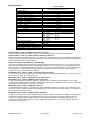
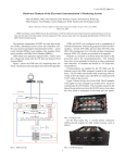
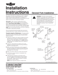
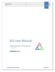
T-GEN 50 24V Alert & Evacuate Tone Generator INSTALLATION AND OPERATING INSTRUCTIONS The VIGILANT T-GEN 50 is a self-contained AS 2220 and ISO 8201 Alert and Evacuate tone generator, with speaker line supervision and speech. It has been designed to connect directly to fire alarm panels, but may be connected to other suitable digitised equipment. T-GEN 50 is available in 2 versions (see page 8 for a full list of available items and accessories): PA0766 Tones, fault supervision and speech. Contains (SF0341) – Speech IC with 4 pre-recorded messages that are inserted into the Alert and Evacuate tones. A microphone input is also provided for emergency public address and for recording messages different to the standard messages supplied. A suitable microphone is Part Number ME0290. PA0886 Same as PA0766 except fitted with SF0309 software and SF0342 speech IC in which the alert message is a recorded bell sound. Alert and evacuate tones may separately be disabled so only the recorded messages are played. DIP switches 5-8 select different functions. Feature 24 VDC, fault supervision, optional PA microphone Alert Tone (can be separately disabled on PA0886) Pre-recorded Alert speech message Evacuation Tone AS 2220 or ISO 8201 selectable Pre-recorded Evacuation messages selectable Microphone input for emergency public address Custom message recording facility Software and speech IC fitted Switches and links used to select different options Recommended for use in Schools and hospitals PA0766 YES YES YES YES YES YES YES SF0308, SF0341 YES NO PA0886 YES YES/Disable BELL TONE YES/Disable YES YES YES SF0309, SF0342 YES YES These instructions apply to units with V1.70 software onwards. Refer to LT0186 Issue 2.30 for instructions for earlier software versions. A pre-assembled Building Occupant Warning System (BOWS) that utilises the T-GEN 50 is available in 50W and 100W versions (ordering codes FP1021 and FP1022). CHECKING THE KIT Before commencing installation, please ensure that the following items are present and undamaged: 1 x T-GEN 50 Board 1 x Installation & Operating Instructions (LT0186) 1 x Background music loom For connecting an external music source to the T-GEN MUSIC input 1 x 6.3mm spacer Mounting T-GEN on earth stud 1 x M4 washer Mounting T-GEN on earth stud 1 x M4 nut Mounting T-GEN on earth stud 6 x PCB standoffs Mounting T-GEN 1 x 2k7 resistor Optional Isolate Indication 1 x 3k3 resistor ELD for MX4428 & F3200 Ancil Relays 2 x 10k resistor -ALM Input ELD resistor, MX4428 Ancil Relay ELD 1 x 56k resistor 100V line ELD 2 x 100k resistor 2 branch 100V line ELD 1 x 100V Speaker Line Warning Label (LB0648) OPERATION Operation of T-GEN is controlled by the Auto/Isol/Evac (AIE-) input. In the “Auto” position the Alarm input (ALM-) is enabled. In the “Isol” (Isolate) position the Alarm input is disabled and any latched fault or alarm conditions are reset. In the “Evac” position the Evacuate tone is generated. In Auto mode activation of the Alarm input starts a six stage rising amplitude Alert tone. This continues until one of the following occurs: - the Alarm input returns to normal (Alarm input in non-latching mode), or the AIE- input is changed to Isol, or the AIE- input is changed to Evac, or the Alert to Evacuate change-over time is reached. If the Alert to Evacuate change-over time is set to 0 sec, then no Alert tone is generated and the Evacuate tone is generated immediately. If the change-over time is set to Alert only, no Evacuate tone is generated and must be initiated LT0186 Issue 2.80 27 July 2012 Page 1 of 10 manually. On the PA0766 model Alert and Evacuate voice messages are automatically inserted in the Alert and Evac tone sequences respectively. Messages shorter than 0.5 seconds are not inserted. Generally the AIE- is left open (Auto) and operation of the T-GEN is controlled via the ALM- input from the fire panel. A switch for the Isolate and Evacuation positions should be fitted only when there is no other warning system isolation facility (e.g., on older AS1603.4 panels). For this arrangement, consideration should be given to indicating the isolate position via a hard-wired yellow LED or fault condition on the fire panel (see Section 3.1). If the 100V line is over-loaded (e.g. short circuit), T-GEN will shut down its amplifier output until the fault is removed. A test mode is provided for testing the 100V line and speakers. To activate this put T-GEN in Auto and fit the Test Link (LK4). T-GEN will produce a short 500Hz tone burst every 4 seconds at low volume (-30dB). (Excludes Wail and Hee Haw for PA0766 and AS2220 for PA0886). PA0886 may be used for voice only applications (disable tone generation). Operating the ALM- input will activate the alert message, operating the A/I/E- input will activate the evacuate message. Slave Mode In slave mode T-GEN does not produce its own tones but connects to a Master T-GEN via the SIG terminals. When connecting T-GENs together there must be only one Master T-GEN. Note that only the Master generates the tones and background music, and is connected to the panel Alarm output and Auto/Isol/Evac switch. All slaves (max 20) and the Master T-GEN must be co-located and share the same 0V. Fault Monitoring If Alarm input fault supervision is enabled, then an open circuit on the ALM- input will cause a fault condition. Detection of an open or short circuit on the 100V line output (Master or Slave mode) or the SIG input (Slave mode only) will also cause a fault condition. A fault condition will turn on the Fault LED and depending on Link 7 activate the Fault Relay or the DEF- output. Note that the 100V line is not supervised for the first 60 seconds after power up to allow the monitoring capacitors to charge up. Note that the fault output is disabled when the T-GEN is in “Isol”. Public Address The operator may use the PA microphone (part number ME0290) for emergency public address. This is activated when the microphone’s PTT button is pressed while the A/I/E switch is in the Auto or Evac position. Public address overrides Alert and Evac tones. A remote microphone can be connected to the T-GEN for general paging by using the PA0688 microphone preamp. Details are contained in the PA0688 Microphone Pre-Amplifier Module User Manual (LT0371). Evacuation Messages The four messages are defined as Msg1, Msg2, Alert and ISO8201 keywords. Refer to the table for the actual prerecorded phrases. PA0766 will play the alert message during alert, Msg1 (or Msg1 + Msg2 if recording is longer than 4 seconds) during AS2220 or ISO8201 Evac if SW8 is off, Msg2 during AS2220 if SW8 is on, and just the ISO8201 keywords during ISO8201 if SW8 is on. PA0886 will play a bell sound instead of the Alert tone and alert message. It will play Msg1 (or Msg1 + Msg2 if recording is longer than 4 seconds) during AS2220 Evac (SW6 and SW8 OFF) if LK4 is OFF and just Msg2 if LK4 is ON (TEST Mode is not available in AS2220 Mode). In ISO8201, Msg1 (or Msg1 + Msg2 if recording is longer than 4 seconds) will be played back after the second keyword. If no Evac message is present, PA0886 will play ISO8201 with keywords only. Recording Messages The T-GEN supports 2 recordable messages, Alert and Evac. Alert can be up to 4 seconds duration. Evac consists of two factory-programmed messages (Msg1 and Msg2) that can be up to 7.2 seconds in total length. The Alert and Evac messages can be re-recorded using an ME0290 PA microphone. To record a message use the following steps (when T-GEN is not in alarm or evacuate or test mode): 1. 2. 3. 4. 5. Fit link LK3 - REC EN on the PCB. This enables the recording and playback of messages. Select the message to be recorded (played) using switch 2 - T1 as follows: T1 Off - Evac message T1 On - Alert message Press the microphone button to start recording. Recording will continue until either the button is released or the maximum message length has been reached. (See NOTE). The recorded message can be played back using the Play button. Note that if the A/I/E switch is not in the Isolate position the played back message will be broadcast over the speaker system. Recording is not broadcast. When recording has been completed, re-set T1 to its original position and remove Link LK3 to disable the record function. NOTE: Messages less than 0.5 seconds will not be broadcast (this can be used to delete an unwanted message). Note that if Evac Msg1 is replaced with a message of more than 4 seconds duration, Evac Msg2 will also be overwritten. LT0186 Issue 2.80 27 July 2012 Page 2 of 10 CONFIGURATION 1. Dip Switch settings Sw1 (T0) Sw2 (T1) Sw3 (T2) Alert to Evacuate Change-Over Time Sw4 (Mon) Alarm I/P Fault Supervision OFF OFF OFF 0 sec OFF Disabled ON OFF OFF 30 sec ON Enabled OFF ON OFF 1 min ON ON OFF 1.5 min Sw5 (Lat) OFF OFF ON 3 min OFF Alarm I/P (PA0766) Non-Latching ON OFF ON 5 min ON Latching OFF ON ON 10 min ON ON ON Alert Only Sw6 (Ev0) Sw7 (Ev1) Sw5 (Lat) Evacuate Tone Alert Tone (/PA0886) OFF No Alert Tone – only recorded message ON Alert tone plus recorded message PA0766 Sw8 (Att) Evacuate Message Selection (PA0766) OFF OFF AS2220 ON OFF RH3 OFF ON ISO8201 + keywords OFF Msg1 or field recorded ON ON Wail (LK4 not fitted) ON Msg2 in AS2220 or Keywords only in ISO8201 ON ON Hee Haw (LK4 fitted) SW6 (Ev0) SW8 (Att) LK4 (test) Don’t Care Evac Message OFF OFF OFF OFF OFF OFF OFF OFF ON ON OFF OFF ON OFF Present OFF ON ON Don’t Care ON OFF OFF None ON OFF OFF Present ON ON ON OFF ON ON ON OFF ON Don’t Care Don’t Care Don’t Care 2. None (relative to Evac Tone) Evac Tone (PA0886) Sw7 (Ev1) AS2220 evacuate only OFF Present AS2220 plus Msg1 ON Present None AS2220 plus Msg2 ISO8201 + keywords ISO8201 + keywords + Msg 1 TEST mode Wail sound, no message Name Msg1 Msg2 Alert ISO8201 Keywords Msg1 only Message Control (PA0886) Recorded Message stops on Input Cancel Recorded Message Plays at least once Recorded Message “Evacuate the building using the nearest fire exit” “Evacuate as directed” x2 “The fire alarm system has operated. Standby for further instructions” “Emergency” “Evacuate Now” TEST mode RH3 sound, no message TEST mode Links Link 1 Name BIAS 2 3 4 MASTER REC EN TEST 5 6 7 SLAVE SLAVE / MASTER FAULT= DEF-/RELAY 3. Control VR1 VR2 VR3 Function Amplifier bias disable. Fit link to reduce quiescent current if T-GEN is to be used with tones only (no speech or background music). Fit for master, remove for slave. Fit to record message. Refer OPERATION. Fit for test tone (500Hz pulsing on/off at -30dB). Operates in “Auto” only and excludes AS2220 for PA0886, Wail & Hee Haw. Fit for slave mode only. Read only on power up. Selects slave or master mode - fit as appropriate. Enables the operation of either the Fault Relay or the DEF- output. Fit in DEF- or RELAY position as appropriate. (DEF- used on NZ panels only) Level Controls Name BIAS SPEECH VOL PA VOL LT0186 Issue 2.80 Function Amplifier Bias – Factory adjustment only. Volume adjustment for recorded messages. Volume adjustment for PA microphone. 27 July 2012 Page 3 of 10 INSTALLATION INSTRUCTIONS 1. MOUNTING T-GEN has the same mounting holes as an MX4428 responder or F3200 card so it can be mounted in an MX1, MX4428 or F3200 cabinet using the mounting holes provided, or in an F3200 card frame. The 5 PCB standoffs required for mounting T-GEN are supplied, and require 6mm diameter mounting holes on a 90 x 90mm pattern. Note that T-GEN must be earthed (refer 3.7). The T-GEN heatsink is at +27V and under full load may reach a high temperature, so all wiring must be kept clear of the heat sink and air should be able to flow freely around it. No part of the cabinet, card frame or wiring must touch the heat sink. For information regarding legacy NZ panels, please refer to LT0233. The 3U 19” rack mounting version (FP0698) should be fitted to the 19” rack cabinet using the included mounting hardware. If the Auto/Isolate/Evacuate switch is required (not recommended for fire panels complying with AS 4428.1 or AS 7240.2) remove the plug and fit the keyswitch supplied loose. Wiring is detailed in Section 3.1. This is a Class A product. In a domestic environment this product may cause radio interference, in which case the user may be required to take adequate measures. 2. SPEAKER WIRING 2.1 100V SPEAKER LINE WIRING The T-GEN has 100V line supervision, and therefore requires a decoupling capacitor at each speaker transformer and a 56k resistor ELD on the end of the line. If wiring on two branches then two 100k ELDs are used, one on each branch. The capacitors must be bipolar, and their value should be 1 - 5uF per Watt of their speaker’s load (see below). See Figure 2.1 for wiring details. Speaker Load Capacitor 0.33W - 0.5W 1uF 1W - 5W 10uF 10W - 20W 47uF 40W 100uF It is possible to use a higher value capacitor on all speakers, however if there are a large number of speakers on the line then T-GEN may indicate a fault after power up. This will clear after a few minutes once the supervision voltage on the line has stabilised. The capacitor’s voltage rating must be at least 10V. T-GEN 50 T-GEN 50 ( See Note 1) EOLR 56K Line EOLR 100K Line ( See Note 1) ( See Note 1) EOLR 100K SINGLE LINE 50 W MAX DUAL LINE 50 W MAX TOTAL Note 1. Capacitor 10V bipolar. Value 1-5 uF per Watt of speaker load. Figure 2.1 Speaker Line Monitoring 100V a.c. audio line wiring is defined as LV Telecommunications circuits and is subject to the Australian Standard AS/ACIF S009:2006. Ensure that this wiring is appropriately separated and insulated from LV power wiring, ELV and other customer cabling such as detection and control circuits. 100V wiring is required to be double insulated. Note: 2.2 A 100V warning label is provided which should be placed next to the T-GEN 50’s 100V line terminals. SPEAKER / HEADPHONE OUTPUT The T-GEN has an optional 8 speaker / headphone output that can be used to output recorded messages only, when the play button is activated. This speaker output is not disabled when the A/I/E switch is in the Isolate position. The speaker is connected to terminals J2 and J3 on the PCB. LT0186 Issue 2.80 27 July 2012 Page 4 of 10 3 INPUT WIRING DETAILS 3.1 Auto/Isolate/Evac Switch. The use of the Auto/Isolate/Evac switch is not recommended in fire panels compliant with AS 4428.1 or AS 7240.2, as the isolate facility on this switch is a duplication of the AS 4428 Warning System Isolate or AS 7240 Alarm Devices Disable function already provided on these panels, and there is no indication of the Isolate position. However, the switch may be useful with older AS1603.4 fire panels, in which case the Isolate position should be indicated. An LED (and resistor) could be wired to turn on in the Isolate position via a spare switch contact (Figure B), or a fault could be generated on the fire panel when the switch is in the Isolate position. For example, wire the ELD 0V connection through the Auto and Evacuate switch contacts so a fault is generated in the Isolate position (Figure C). Alternatively, if the Isolate position is to be disabled (but the Auto and Evacuate positions retained) remove the 10k resistor from the Isolate switch and blank off the word “Isolate” on the label. +24V EVAC 2K7 T-GEN 50 MASTER A/I/E- EVAC ISOL Yellow LED ISOL COM ELD EVAC 10k 0V ISOL AUTO AUTO AUTO 0V 0V A/I/E- Switch Wiring Figure A Isolate Indication via Spare Switch Pole Figure B Using Isolate Position to Generate Fault Figure C 3.2 Background Music/Remote Paging An external audio source can be connected to the T-GEN MUSIC input, J9, for background music, external paging, etc. This source must have an isolated output, otherwise an audio isolating transformer, e.g. the ALIM9706 (part number PA0646), must be used. Refer to LT0372 for the ALIM wiring arrangement. A background music loom adapter consisting of a 2 way plug with red (SIG) and black (GND) wires is supplied with the T-GEN. Sound System SIG 2.5Vrms max GND Mic Preamp (see LT0371) RED BLACK T-GEN 50 Master Music 2 J9 1 Screened cable Remote paging (non-emergency) can be achieved by using the PA0688 microphone preamp board. Refer to LT0371 for details. 3.3 Microphone An emergency PA microphone (part number ME0290) can be connected to J1 on the T-GEN. J1-1 MICJ1-2 MIC+ J1-3 PTT J1-4 PTT For a remote emergency PA microphone, refer to LT0371 for using a PA0688 microphone preamp. LT0186 Issue 2.80 27 July 2012 Page 5 of 10 3.4 T-GEN Wiring - Separate Alarm & Fault Wiring 0V SUP MX1 ANCIL Relay (See Note 1) NC C NO Note 2 0V FLT RED +24V BLACK 0V BLUE ALM- FLT YELLOW NO Fault FLT 0V YELLOW +24V 0V 10K ALMFLT 0V VBF+ ALM- +24V ALM Relay Output F3200 Relay Bd, IOR, ADC130 ELD 10K See Note 3 +24V 0V Open Collector Output IOR F3200 etc T-GEN 50 3U Panel (FP0698) 0V ALM - ALM - ELD 10K 0V FLT COM T-GEN 50 Master (Note 4) +24V +24V 0V 0V ALM SIG NO Fault COM Input IOR ADR ADM13X etc FP1600 MK3 Sigma 5 Omega 64 MK3 BELLS (See C/+ Note 5) FLT T-GEN 50 Slave (Note 4) FLT 0V +24V +24V 0V 0V FLT ALM 0V SIG 10K BELLS - NO ALM FLT0V FLT0V ELD (see Note 6) E.g., PA0729 GP Relay Board (12V Relay) 4100ES WARNING (Note 7) SPS Aux +24V Power 0V 4100-3003 Relay Module Relay & COM FB Input NO FB Fault COM +24V 0V FLT 0V 10K EOL ALMFLT If powering a T-GEN50 via the SPS Aux power output the speaker load must not exceed 40W Notes 1. Please refer to MX1 LT0360 Installation Manual (NZ) or LT0439 Operator Manual (Australia) for more information. Use LM0319 (MX1/T-GEN Loom) or FP0698 3U Panel (see Note 2). 2. FP0698 3U panel comes with premade loom with connector for MX1 use (ANC1 J4). For use with other panels remove connector and wire as shown above. 3. Requires connection to a monitored 24V supply (FP1600/Sigma 5/Omega 64 Mk3/4100ES). 4. Switch SW4 ON for the Master T-GEN. Fit LK7 in Relay Position for all T-GENs. 5. FP1600/Omega 64 Mk3 boards have three 7-segment displays. 6. ELD value depends upon Input type (not fitted when used with MX1 or 4100ES). 7. The SPS Aux Power output is rated at 2A which is sufficient to power only 1 T-GEN 50 with a maximum speaker load of 40W. Please refer to LT0394 or LT0350 for further details on using the T-GEN 50 with the 4100ES panel. LT0186 Issue 2.80 27 July 2012 Page 6 of 10 3.5 T-GEN Wiring with Combined Alarm/Fault Supervision T-GEN 50 Master (Note 2) F4000/MX4428 (Note 1) +24V + 24V + 24V 0V 0V ALMSIG F3200 + 24V 0V ANCIL 0V Relay NO COM NC SUP +24V 0V 0V ALM ALMNO COM F4000 RRM (Note 3) F3200 Relay Bd C NO NC Relay (Note 4) S + 24V 0V - /C T-GEN 50 Slave (Note 2) ALM0V + 24V + 24V 0V 0V ELD (See Notes 5 & 6) F3200 BELLS Fault SIG NO COM +24V 0V ALM- T-GEN 50 Master (Note 2) Fault WARNING + 24V 4100ES SPS Aux Power (Note 7) 0V + 24V ALM- 0V NC Fault NAC3 BB+ COM EOL 10K If powering a T-GEN50 via the SPS Aux power output the speaker load must not exceed 40W NO Notes 1. Cut “Ancil Sup link” on F4000, MX4428 Main Board. 2. Fit Lk7 in Relay position to enable Fault Relay. Turn SW4 off. 3. RRM must be inside FIP and wired to RESP IN. 4. Connect wire from NC terminal of relay to “S” pin of supervision link. Do not fit Sup link at all. 5. 3k3 ELD for MX4428 Ancil Relay and RRM, F3200 Ancil Relay and F3200 Relay Bd. (2k5 (3k3//10k) for F3200 Bells. 6. Wire spare pole of AIE switch in series with ELD as per Section 3.1 Figure C if Fault indication required in Isolate. 7. The SPS Aux Power output is rated at 2A which is sufficient to power only 1 T-GEN 50 with a maximum speaker load of 40W. The 4090-9118 Relay IAM can also be used to control and monitor the T-GEN 50. Please refer to LT0394 or LT0350 for further details on using the T-GEN 50 with the 4100ES panel. LT0186 Issue 2.80 27 July 2012 Page 7 of 10 3.6 Connecting T-GEN using the DEF- Output The following wiring is recommended for when the T-GEN is mounted in or adjacent to a fire panel that supports the DEF- signal. Using the DEF- output disables the T-GEN fault relay, and therefore the quiescent current is 17mA lower per T-GEN compared with using the fault relay. But the DEF- line is not supervised for open circuit. Note that link Lk7 on the T-GEN(s) must be fitted in the DEF- position. The power supply for the T-GEN must be supplied from a monitored 24V supply. T-GEN Master Sigma 5 FP1600 Mk3 (Note 3) OMEGA 64 Mk3 (Note 3) NO (see Note 2) +V 0V EOL (see Note 1) C BELLS – EXT DEF - +24V +24V 0V 0V ALM SIG DEF- 0V Resistors removed, (Note 4) T-GEN Slave +24V +24V 0V 0V Notes: 1. Sigma 5, FP1600/OMEGA 64 Mk3 - EOL=10k. Enable ALM- input monitoring on T-GEN - (MON switch ON). 2. Requires connection to a monitored 24V supply. 3. FP1600/Omega64 Mk3 boards have three 7segment displays. 4. Sigma 5 and FP1600/OMEGA Mk3 require resistors to be removed. Remove R15, R16 for Sigma. Remove R62, R63 for FP1600/OMEGA 64 Mk3. SIG DEF - 3.7 Earth Connection The T-GEN must be connected to the cabinet EARTH using either the EARTH terminal on the T-GEN PCB (located beside the 100V Line Output) or by using a metal standoff on the bottom left hand mounting hole (an M4 washer and nut are supplied). 3.8 Power Connection WARNING: Each T-GEN 50 draws approximately 10A for 20 ms when first powered up. Any fuse between the T-GEN 50 and its power supply must be a slow blow type rated 3A minimum (per T-GEN 50). Any switch contact used to supply power to a T-GEN 50 must also be rated at 10A minimum (per T-GEN 50). The T-GEN 50 presents a significant capacitance (6600µF) on its power terminals, hence the high inrush current. This capacitance can also invalidate the battery connection tests (that lower the charger voltage to see if the battery is still present) on some power supplies (e.g. 1948 PSU) if the T-GEN 50 is the only device powered by the PSU. In this case it may be necessary to add a power resistor to the PSU output to provide extra standing load. For the 1948 24V PSU a 820 ohm 5W resistor is typically required. Note the 33mA this resistor draws needs to be included in any battery capacity calculations. LT0186 Issue 2.80 27 July 2012 Page 8 of 10 SPECIFICATIONS Supply Voltage Quiescent Current Fault Relay Disabled Tones Only (Bias link LK1 fitted) Audio (Bias link LK1 not fitted) Fault Relay Enabled Tones Only (Bias link LK1 fitted) Audio (Bias link LK1 not fitted) Active Current - 50W at 27Vdc Line Voltage - AC (Tones) - DC (Supervision) Line Power - Tones - Audio Line Supervision ELD - 1 Branch - 2 Branches Inputs ALM- A/I/E- ALM- / A/I/E- Input Current Background Music Input SIG Input (Slave) /Output (Master) SIG Input Supervision Voltage Microphone - Input Level Speaker Output (internal) - Load impedance PA0766 / PA0886 19.2Vmin - 28.8Vmax Reduced performance below 27.0V 32mA 47mA 49mA 64mA 2.2A 100V rms 2.5V (56k ELD 5.5V (O/C)) 50W rms 25W rms Yes 56k 0.4W 100k 0.4W O/C = Fault 3V - 5V (if supervision enabled) 3k3 - 10k = Normal 1V - 3V S/C = Alarm 0V - 1V O/C = Auto 3V - 5V 10k = Isolate 1V - 3V S/C = Evac 0V - 1V 0.7mA at 0V 2.5Vrms into 27k non-isolated for full power 3Vpp max 12Vdc (1/2 supply voltage) 3mV rms - 100mV rms 8 min 6mW PA0766 PCB Assy,1955-1-3,T-GEN,Tones,Flt Mon, PA Speech Standard model of T-GEN with SF0341 speech IC pre-recorded messages for Australia and New Zealand. PA0886 PCB Assy, 1955-1-3, T-GEN, NZ Bells and Speech, Flt Mon, PA Similar to PA0766, but has SF0342 speech IC with a bell sound recorded instead of the alert message and has different software to support playing the messages only (no tones). Hee-Haw tone is not supported, and the Wail and RH3 tones cannot have the Evacuate message inserted. FP0698 FP, T-GEN, 3U Rack Mtg Panel, C/W PCB & Mic A 3U 19” rack mounting module complete with a PA0766 T-GEN 50 mounted on the back of it. A microphone and front panel label are supplied fitted to provide a complete functional unit. A loom for power, control and monitoring is factory fitted. The loom is connectorised for direct use with MX1. The connector can be removed and the loom wired into other panels if required. An Auto/Isolate/Evacuate keyswitch is included loose for fitting if required. Wiring to the 100V speaker line is also required to make it operational. ME0289 Mech Assy, 1955-16, T-GEN, 1U Rack Mtg, A/I/E Control Panel A 1U 19” rack mounting module that has a 3 way rotary switch and Auto/Isolate/ Evacuate label on it, wired so that it can be connected to T-GEN. No T-GEN is included. ME0290 Mech Assy, 1955-3, T-GEN/MVAC Dynamic Microphone ME0490 Mech Assy, 1955-44, T-GEN 50, Dynamic Microphone A noise-cancelling dynamic microphone suitable for plugging onto the T-GEN to provide emergency PA or for field recording of the digitised speech message(s). ME0290 has a 1m coiled cord. ME0490 has a 1m extension to this coiled cord, suitable for internal routing in the cabinet, if required. ME0291 Mech Assy, 1955-24, T-GEN A/I/E Switch Kit A small metal bracket containing a 3 position rotary switch, labelled and wired for connection to the T-GEN A/I/E- input. This allows control of T-GEN’s operation through selection of the Auto, Isolate and Evacuate positions. The bracket can be mounted in most fire alarm panels. ME0292 Mech Assy, 1955-25, T-GEN Empty Box, Keyed 003 A 240W x 295H x 85D, cream wrinkle coloured, locked, metal box suitable for mounting the T-GEN (not included) inside. A standalone tone generator and PA announcement system can be constructed by using the T-GEN mounted in a cabinet (e.g., ME0292), together with the ME0291 Auto/Isolate/Evacuate switch, and the ME0290 microphone. A suitable power supply is also required, (e.g. Series 1948 24V 2A (FP0766) and 2 x 6.5Ah hour batteries - this is the same size as the T-GEN box). LT0186 Issue 2.80 27 July 2012 Page 9 of 10 Manufactured by: LT0186 Issue 2.80 Tyco Fire Protection Products 17 Mary Muller Drive, PO Box 19-545 Christchurch, New Zealand Tel +64-3-389 5096 Fax +64-3-389-5938 Distributed by: 27 July 2012 Page 10 of 10