1
RAYMOND OGIENOYEVBEDE
EMBEDDED KIT FOR EMBEDDED
SIMULATION AND TROUBLESHOOTING
SOFTWARE
THESIS
CENTRAL
SCIENCES
OSTROBOTHNIA
UNIVERSITY
OF
APPLIED
DEGREE PROGRAMME IN INFORMATION TECHNOLOGY
MAY 2012
CENTRAL OSTROBOTHNIA
Date
UNIVERSITY OF APPLIED
SCIENCES
[MAY 2012]
Author
RAYMOND
OGIENOYEVBEDE
Degree programme
BACHELORS DEGREE IN INFORMATION TECHNOLOGY
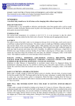
Name of thesis
EMBEDDED KIT FOR EMBEDDED SOFTWARE SIMULATION AND TROUBLESHOOTING
Instructor
Pages
JOHNNY VIDJESKOG
[54]
Supervisor
MÄNNISTÖ SAKARI
Arduino based kit (SADET) is a hardware toolkit for testing embedded
software of various designs. It includes multiple inputs and outputs
components that can be adapted for different test purposes. In this work, we
look at Arduino Nano as a design platform for embedded systems and
embedded software courses and explore the possibility of it being suitable for
teaching Information Technology students embedded courses. SADET is a
project based kit that not only introduces embedded systems and its
interaction with embedded software but also give easy access to the complex
nature of a micro-controller. It provides a flexible inexpensive interface with
its core component as the Arduino Nano that has the ability to accept multiple
inputs and indicates output through multiple outputs according to the
running loaded embedded software. SADET is built with eight input terminals
and five output terminals using three different prototype circuits for the
purpose of it to be used as a teaching aid for embedded systems and
embedded software lectures. Regardless of it being built from three prototype
circuits, its multiple inputs and outputs allows it to be used to test the
operation of limitless number of circuit prototypes by loading and running
prototype software of choice. This reduces the need to build different circuits
for lecture purposes.
Key words
MICROCONTROLLER, EMBEDDED KIT, EMBEDDED SOFTWARE
ABSTRACT
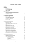
TABLE OF CONTENT
1 INTRODUCTION ------------------------------------------------------------------------------ 1
2 BACKGROUND AND MOTIVATION -------------------------------------------------- 3
3 CURRENT EMBEDDED SOFTWARE COURSE -------------------------------------- 6
3.1 Main Topics ------------------------------------------------------------------------------------- 7
3.2 Examples and Exercises (Simulator) ------------------------------------------------------ 8
4 ARDUINO BASED KIT FOR PRACTICALS ------------------------------------------- 9
4.1 Embedded Systems Hardware Structure (Kit) ---------------------------------------- 10
4.1.1 General Structure (SADET) -------------------------------------------------------------- 10
4.1.2 Operation ------------------------------------------------------------------------------------- 15
4.1.3 Car Alarm System -------------------------------------------------------------------------- 18
4.1.4 Operation ------------------------------------------------------------------------------------- 21
4.1.5 Garage Door System ----------------------------------------------------------------------- 23
4.1.6 Operation ------------------------------------------------------------------------------------- 26
4.1.7 Dice Rolling System ----------------------------------------------------------------------- 27
4.1.8 Operation ------------------------------------------------------------------------------------- 30
4.2 Embedded Software ------------------------------------------------------------------------- 32
4.2.1 Arduino Independent Development Environment (IDE) ------------------------ 32
4.2.2 Arduino Programming with C Language -------------------------------------------- 38
4.2.3 Sample Code for Car Alarm System --------------------------------------------------- 41
4.2.4 Sample Code for Garage Door System ------------------------------------------------ 44
4.2.5 Sample Code for Dice Rolling System ------------------------------------------------ 46
5 Usage of Embedded Kit ---------------------------------------------------------------------- 50
5.1 From Connection to Code Simulation --------------------------------------------------- 51
6 CONCULSION --------------------------------------------------------------------------------- 52
REFERENCES ------------------------------------------------------------------------------------- 54
GRAPHS
GRAPH 1. Front View of SADET (Embedded kit) ---------------------------------------- 12
GRAPH 2. Inside View of SADET (Embedded kit) --------------------------------------- 14
GRAPH 3. SADET prototype on Bread Board --------------------------------------------- 14
GRAPH 4. SADET -------------------------------------------------------------------------------- 15
GRAPH 5. 7-Segment Display pins label ---------------------------------------------------- 17
GRAPH 6. Schematics of SADET ------------------------------------------------------------- 18
GRAPH 7. Car Alarm System on front view ----------------------------------------------- 19
GRAPH 8. Car Alarm System Schematics -------------------------------------------------- 20
GRAPH 9. Car Alarm System Prototype of Bread Board ------------------------------- 21
GRAPH 10. Garage Door System on front view ------------------------------------------- 24
GRAPH 11. Garage Door System Schematics ---------------------------------------------- 25
GRAPH 12. Garage Door System prototype on Bread Board -------------------------- 26
GRAPH 13. Dice Rolling System on front view ------------------------------------------- 28
GRAPH 14. Dice Rolling System Schematics ----------------------------------------------- 29
GRAPH 15. Dice Rolling System prototype on Bread Board --------------------------- 30
GRAPH 16. 7-Segment Display pins label -------------------------------------------------- 31
GRAPH 17. Arduino IDE ----------------------------------------------------------------------- 33
GRAPH 18. Arduino IDE when load example sketch (code) -------------------------- 33
GRAPH 19. Arduino IDE when selecting microcontroller type ----------------------- 34
GRAPH 20. Arduino IDE when selecting Universal Serial Bus communication port
---------------------------------------------------------------------------------------------------------- 35
GRAPH 21. Arduino IDE when compiling a sketch (code) ----------------------------- 36
GRAPH 22. Arduino IDE when uploading a sketch (code) ---------------------------- 37
TABLES
TABLE 1. Simulation Exercises ------------------------------------------------------------------ 8
TABLE 2. Input Switches ------------------------------------------------------------------------ 10
TABLE 3. Outputs -------------------------------------------------------------------------------- 11
TABLE 4. Component List ---------------------------------------------------------------------- 13
TABLE 5. Input Connections ------------------------------------------------------------------- 16
TABLE 6. Output Connections ---------------------------------------------------------------- 16
TABLE 7. Test combinations of Car Alarm System --------------------------------------- 23
1
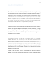
1 INTRODUCTION
This thesis comprises of embedded hardware and embedded software
information. First it introduces the embedded system courses as presently taught
to students such as their main topics, examples and exercises, and afterwards it
describes how to design and implement an embedded kit using various electronic
components and its main component being an Arduino Nano. It also further
instructs on how to use the kit to demonstrate and test embedded software
example programs.
Knowing that the electronics and embedded system is not a major line of
concentration for the information technology degree program students, using an
easy understandable kit with the Arduino Nano will help capture the heart of
many non-electronics engineers. Using Arduino and related open source project as
a platform for teaching embedded courses, provides a room for continuous
exploration and innovation for students regardless of their choice of course-major.
Viewing what is expected by a student from the electronic and embedded system
courses at undergraduate level, using Arduino serves as good introduction to the
concept of embedded system and due to it being an open source project there is
the opportunity for every student to continue self exploration and show their
creativity as much as possible.
Arduino Nano simplicity gives an easy means for student to build devices that
would be harder to implement with other embedded platforms. The Arduino
community, which consists of not only engineers and scientists, but also a large
2
collection of hobbyists, gives student the opportunity to get design ideals, access
to large knowledge databases and encouragement to get something working even
after the courses are over.
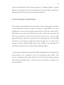
This work also shows an embedded kit created using an Arduino Nano with
multiple inputs and outputs which can be adapted for various purposes. The
creation of the embedded kit known as “SADET” was made using three prototype
circuits and all needed inputs and outputs of the circuits where provided.
Implementing eight inputs and five outputs, SADET was created from the
prototypes; garage door system, dice rolling system and car alarm system, all
adapted from the embedded software lecture for which the embedded kit was
created for in order to ease the testing of embedded software written during the
lecture.
The inputs are switch acting as sensors, actuators and signal acceptors, which are
normally found on device hardware and the output, comprise of visual indicators
such as light emitting diodes (LEDs), sound indicators such as a buzzer and a 7segment display for numerical visual appeal. The functioning of SADET was
demonstrated using sample codes created individually for each system from
which it was combined. Each code was written, compiled and uploaded into the
microcontroller
of
Environment (IDE).
SADET
using
the
Arduino
Integrated
Development
3
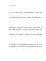
2 BACKGROUND AND MOTIVATION
In the generation of electronics and smart machines, embedded systems play a
very important role in the continuous growth and ideal actualization in the field.
Embedded system growth has been progressive and fast within the past two
decade, and with the implementation of semiconductors into electronics, the size
and availability of embedded systems both as study prototypes and final products
have become manageable and steady. In order to foster the rapid growth of
embedded system and software, there has been steady improvement of embedded
system, and software education and introduction of students into time-oriented
programming which is a key factor in the operation of embedded system and
software.
Embedded systems introduced to a student in the field of information technology
exist as a late add-on course which reduces the vast exposure needed for students
to grasp completely the concept required to further explore the field. A quick view
at the programming method that students are exposed to at the beginning of their
study time, reveals a data-oriented study method which is not the targeted timeoriented programming needed for the programming of embedded systems and
software. To encourage students to explore more about embedded system and
software, early introduction of a structured time-oriented programming method
may help and with the early introduction of electronics and electronic
components, embracing the ideal of working with virtual microcontroller that
exposes and introduces low-level resources of embedded systems and alongside
higher-level abstraction of how hardware and software are intertwined.
4
Embedded systems and embedded software programming with a modified
version of C programming language commonly known as Embedded C, show a
modified version of a time-oriented programming method that implements
hardware configuration into basic programming. The configuration is made easy
with a set of easy to use tools that support the hardware being configured, C
captured,
compiled,
simulated,
debugged
and
a
programmable
virtual
microcontroller. It should also enable the uploading through specific interface into
the physical hardware microcontroller.
An early introduction into the field of embedded systems and software and a
continuous steady growth in an environment where ideal exploration is the order
of the day, the development of an ideal oriented physical prototype of a device
implementing a programmable microcontroller is achievable. Students that are
predisposed to electronics and those that welcome new ideals and challenges to
test their imagination and creativity can be nurtured and encouraged by making
their impression of exploring the field embedded systems and software an
interesting and innovative one.
Students of information technology have less chance of embracing embedded
systems and software but with early introduction to time-oriented programming
and electronics, the desire to venture into embedded systems and software can be
stirred up. An opportunity to capture students and encourage their interest in
embedded systems and software is during the course of embedded systems and
software. The lecture time should expose the advantages of knowing embedded
systems and software and the freedom of being creative with one’s ideals when a
student understands the concept. A better way to show this is to conduct the
5
lecture with a prototype device showing the capability of embedded systems and
software.
This thesis shows how a prototype device is created and can be used in the
practical lecture of embedded systems and software and the possibility for every
student to become creative and expatiate on the ideal behind the creation.
6
3 CURRENT EMBEDDED SOFTWARE COURSE
The current embedded software course shows an encouraging introduction into
smart systems for students with previous knowledge of electronics, electronic
components and digital circuits. An Integrated Development Environment (IDE)
with microcontroller hardware simulated support is used on the course. The
complimentary course (Embedded System) introduces the general architecture
and internal structure of a microcontroller and its interactions with external
circuits. The practical aspect is conducted with the aid of a Keil uVision
compactable hardware.
The course structure presents itself as organized and educative. Reflecting on it
from the view of a degree program in information technology, students in this
program are focused on networking and programming, embedded systems and
software being a minor focus. Using the above course structure leaves no room for
self-expansion and creativity because the tools, especially the hardware
components with the implementation of the microcontroller cannot easily be
modified or improved upon. Knowledge gained from this course structure
requires more research for it to be useful in the pursuit of the implementation of
embedded systems and software for professional and leisure use.
Information technology students with embedded systems and software as a minor
focus tend to prefer to use the knowledge for leisure purpose. With the
introduction of a hardware and IDE (Integrated Development Environment)
structure that support such usage will add more value to the course. Research
7
made into the open source project in embedded system and software known as
ARDUINO project comprised of microcontroller boards, related IDE and support
website. This thesis implements Arduino Nano as a case study for student and
shows how it can be implemented in the embedded system and software courses
and generally stirs student interest in using it for leisure design due to its ease of
usage.
3.1 Main Topics
Presently the embedded software course introduces students to these topics.
(adapted from Central Ostrobothnia University of Applied Sciences 2012)
1. Introduction to Embedded Systems
2. HW related extensions to C
3. Port I/O
4. Program development and testing in simulator
5. Interrupts
6. Timer and Timer Interrupts
7. State Machines
8. Time Triggered Architecture
8
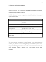
3.2 Examples and Exercises (Simulator)
Practically using the Keil uVision IDE (Integrated Development Environment),
students are taught the below examples:
TABLE 1. Simulation Exercises (adapted from Central Ostrobothnia University of
Applied Sciences 2012)
Example
Learning Goals
Seat Belt Alarm
One bit i/o. C-extensions to handle i/o. IDE and
simulator.
Seat Belt Alarm*
Good software structuring
Dice
Byte-level i/o. Software and test design.
Up/Down Dice
Introduction to system states
Door Opener
Modeling based on state charts. State chart
implementation. Timing
Door Opener with integrated Time Triggered Architecture
burglar alarm
The above examples are taught in a virtual hardware testing environment and
students gets physical device for testing during the embedded system course.
Using a virtual testing environment may render desired solutions but exclude the
visual knowledge of how a physical device would respond to tests being
performed.
9
4 ARDUINO BASED KIT FOR PRACTICALS
Arduino may eliminate the low-level challenges of embedded system hardware
and software design which as a minor subject is not of great importance but the
student will still experience a large majority of the concepts from its shared
simplicity and with the added benefit of building working and interesting designs
with minimal difficulty. The student will be provided a multipurpose microcontroller that can be incorporated into any electronic circuit as flexible as the
imagination of the student and each micro-controller can be programmed with clanguage. Part of the information technology degree program curriculum is clanguage course thereby further easing the embedded software programming.
Accompanying the hardware is a programming kit that provides an integrated
development environment (IDE) and with this creating and uploading a program
into the micro-controller is simplified.
Practicals for the embedded systems and software courses are mainly performed
in a virtual hardware platform which does not satisfy the curiosity of students on
how real physical devices would respond to the activities and codes created by
them. This chapter will illustrate how a physical device is created to be used in
place of the virtual hardware device for embedded software code testing.
10
4.1 Embedded Systems Hardware Structure (Kit)
The thesis involves the actual creation of an embedded kit (SADET) using
electronic components. SADET is an embedded system using the Arduino Nano
that was created to be used for embedded software testing. The device created has
enough inputs and outputs so that it can be used to demonstrate and test most
examples used in present COUAS embedded software course.
4.1.1 General Structure (SADET)
SADET was created and tested incrementally by combining three example circuits
used in the embedded software course, namely CAR ALARM, GARAGE DOOR
and DICE ROLLING SYSTEM. To be able to demonstrate and test each of these
systems SADET needed to have eight input switches;
TABLE 2. Input Switches
PUSH BUTTON (PB). For
partial
contact
in the
circuit.
GRAPH 1. Push Button (adapted from Digi-Key
Corporation 2012)
11
FLIP SWITCH 1 (S1)
FLIP SWITCH 2 (SW1) –
FLIP SWITCH 7 (SW6).
For continuous contact in
the circuit.
GRAPH 2. Flip Switch (adapted from Digi-Key
Corporation 2012)
These switches are connected to Arduino input pins and can be used through
proper configuration. Attached to SW1 to SW6 are six RED light emitting diodes
(LED) labeled LED1 through to LED6. The LEDs indicates when a corresponding
switch is turned OFF or ON.
Based on the three aforementioned examples there was need for three LED
outputs, one buzzer and a 7-segment display;
TABLE 3. Outputs
GREEN Light Emitting Diode (D1)
GREEN Light Emitting Diode (D2)
GREEN Light Emitting Diode (D3).
For visible green light display.
GRAPH 3. Light Emitting Diode (adapted
from Digi-Key Corporation 2012)
12
BUZZER (SPK). For audio output.
GRAPH 4. Buzzer (adapted from Rapid
Electronics Limited 2012)
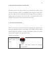
7-SEGMENT Light Emitting Diode
(7-SEG).
For
numeric
output
display.
GRAPH 5. 7-Segment Display (adapted
from Digi-Key Corporation 2012)
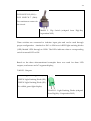
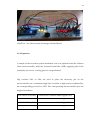
The combination of all input and output components are seen in the front view of
SADET with the input components in the lower half of the device and the output
components in the upper half.
GRAPH 1. Front View of SADET (Embedded kit)
13
The electronic circuitry derived from the above three circuitries from which the
final device (SADET) was created has a combination of the following components
for its final creation;
TABLE 4. Component List
PART
QUANTITY DESCRIPTION
PUSH BUTTON
1
creates make-and-break contact
FLIP SWITCHES
8
creates continuous contact
GREEN LED
3
creates green light
RED LED
6
creates red light
BUZZER
1
gives out buzzing sound
7-SEGMENT LED
1
for number display with LED
300Ω RESISITORS
16
for voltage breakdown
330KΩ RESISTORS
2
ARDUINO NANO
1
hardware holding the microcontroller
4X4 DIP SOCKET
1
socket seats for 7-SEGMENT LED and
15X15 DIP SOCKET
1
ARDUINO NANO
VERO BOARD
1
conducting board
CONNECTION WIRES
for component connection
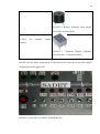
All the components were arranged using the schematics of SADET and soldered to
the Vero board using soldering flux and soldering iron found in the electronics
laboratory.
14
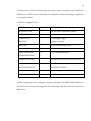
GRAPH 2. Inside View of SADET (Embedded kit)
A gradual process was taken to obtain the final workable circuit. Each step was
connected and tested using similar components mentioned above except that the
Vero board was replaced with a bread board.
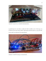
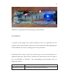
GRAPH 3. SADET Prototype on bread board
15
Individual circuit was tested and a combination of them was also tested to obtain
the final working prototype from which SADET was made including the use of
vero board and manufacturing of the casing.
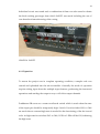
GRAPH 4. SADET
4.1.2 Operation
To ensure the project was in complete operating condition, a sample code was
created and uploaded into the microcontroller. Generally the mode of operation
requires taking input from the multiple input buttons, performing the instructed
operations and sending the output to any or all of the output channels.
Pushbutton PB serves as a contact and break switch which is used when the state
of the input pin should be temporarily high. Switch S1 and switches SW1 to SW6
are used when a constant high state is needed for the functioning of the device and
code. At high state for switches SW1 to SW6, LED1 to LED6 will be ON, indicating
the high state.
16
The input pins are connected as follows:
TABLE 5. Input Connections
COMPONENT
CONNECTION
PUSH BUTTON (PB)
connected to Arduino Nano Digital Pin 2
FLIP SWITCH 1 (S1)
connected to Arduino Nano Digital Pin 3
FLIP SWITCH 2 (SW1)
connected to Arduino Nano Digital Pin 4
FLIP SWITCH 3 (SW2)
connected to Arduino Nano Digital Pin 5
FLIP SWITCH 4 (SW3)
connected to Arduino Nano Digital Pin 6
FLIP SWITCH 5 (SW4)
connected to Arduino Nano Digital Pin 7
FLIP SWITCH 6 (SW5)
connected to Arduino Nano Digital Pin 8
FLIP SWITCH 7 (SW6)
connected to Arduino Nano Digital Pin 9
Outputs are also sent to either any or all of the three LED (D1, D2, and D3) or
buzzer or 7-SEG or any combinations. To use the output pins signals are sent to
the microcontroller pins to which they are connected. The output pins are
connected as follows:
TABLE 6. Output Connections
COMPONENT
CONNECTION
GREEN Light Emitting Diode (D1)
connected to Arduino Nano Digital Pin 10
GREEN Light Emitting Diode (D2)
connected to Arduino Nano Digital Pin 11
GREEN Light Emitting Diode (D3)
connected to Arduino Nano Digital Pin 12
BUZZER (SPK)
connected to Arduino Nano Digital Pin 13
7-SEGMENT Light Emitting Diode Connected to Arduino Nano Analog Pins
(7-SEG)
A0 to A5 and connected to Arduino Nano
Digital Pin 12.
7-SEGMENT Light Emitting Diode (7-SEG) is
17
divided into 10 pins: a, b, c, d, e, f, g, dp, +, +
7-SEG-a
connected to Arduino Nano Digital Pin 12
7-SEG-b
connected to Arduino Nano Analog Pin A0
7-SEG-c
connected to Arduino Nano Analog Pin A1
7-SEG-d
connected to Arduino Nano Analog Pin A2
7-SEG-e
connected to Arduino Nano Analog Pin A3
7-SEG-f
connected to Arduino Nano Analog Pin A4
7-SEG-g
connected to Arduino Nano Analog Pin A5
7-SEG-dp
not connected
7-SEG-+, +
connected
to
5volt
supply
(common
cathode)
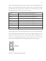
GRAPH 5. 7-Segment Display pins label
It is observed that GREEN Light Emitting Diode (D3) and 7-SEG-A shares
Arduino Nano Digital Pin 12. This is due to the fact that there are not enough
microcontroller pins for all the connections. The selection of which component
uses the Arduino Nano Digital Pin 12 is done through FLIP BUTTON J1.
18
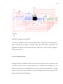
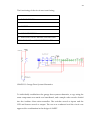
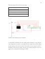
GRAPH 6. Schematics of SADET
Vcc 5volt is supplied to the circuit through Arduino Nano pin 5V and all ground /
earth connections are made to Arduino Nano pin GND. These connections are
supplied through the Universal Serial Bus (USB) port to the external computer /
5Volt power source.
4.1.3 Car Alarm System
Among the three combined circuits from which the final circuit was made is the
car alarm system circuit. Its main function is to simulate the workings of a car
alarm in case there is an unhandled event such as seat belt not fastened or car light
is left on. The circuit uses switches as inputs and light and sound as outputs. The
input switches are the following:
19
FLIP SWITCH 2 (SW1) - FLIP SWITCH 7 (SW6)
and the output indicators are the following:
GREEN Light Emitting Diode (D1)
GREEN Light Emitting Diode (D2)
GREEN Light Emitting Diode (D3)
BUZZER (SPK)
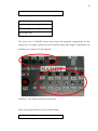
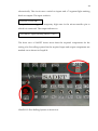
The front view of SADET shows more than the required components for the
testing of a car alarm system, but the required input and output components are
marked out as showed in the diagram.
GRAPH 7. Car Alarm System on front view
The functioning of the circuit was tested using:
6 -- FLIP SWITCHES
20
6 -- RED LED
3 -- GREEN LED
1 -- BUZZER
10 -- 300Ω RESISITORS
1 -- ARDUINO NANO MICROCONTROLLER
BREAD BOARD and CONNECTIONWIRE
GRAPH 8. Car Alarm System Schematics
To individually troubleshoot the car alarm system schematics, a copy using the
same components was made on a breadboard and a sample code was also loaded
into the Arduino Nano microcontroller. The switches served as inputs and the
LED served as output. The test was conducted and the circuit was approved for
combination in the design of SADET.
21
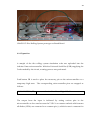
GRAPH 9. Car Alarm System Prototype of Bread Board
4.1.4 Operation
A sample of the car alarm system simulation code was uploaded into the Arduino
Nano microcontroller. With the Universal Serial Bus (USB) supplying the 5volts
needed by the circuit, a testing process was performed.
Flip switches SW1 to SW6 are used to place the necessary pin on the
microcontroller on a continuous high state. Switches at high state are indicated by
the corresponding powered on LED. The corresponding microcontroller pins are
mapped as follows:
FLIP SWITCH 2 (SW1)
connected to Arduino Nano Digital Pin 4
FLIP SWITCH 3 (SW2)
connected to Arduino Nano Digital Pin 5
FLIP SWITCH 4 (SW3)
connected to Arduino Nano Digital Pin 6
FLIP SWITCH 5 (SW4)
connected to Arduino Nano Digital Pin 7
22
FLIP SWITCH 6 (SW5)
connected to Arduino Nano Digital Pin 8
FLIP SWITCH 7 (SW6)
connected to Arduino Nano Digital Pin 9
Each flip switch indicates specific input:
FLIP SWITCH 2 (SW1)
indicates DOOR OPEN
FLIP SWITCH 3 (SW2)
indicates ENGINE RUNNING
FLIP SWITCH 4 (SW3)
indicates KEY IN PLACE
FLIP SWITCH 5 (SW4)
indicates LIGHTS ON
FLIP SWITCH 6 (SW5)
indicates BELT OPEN
FLIP SWITCH 7 (SW6)
indicates DRIVER SITTING
The output from the combinations of inputs is indicated by setting various pins in
the microcontroller to high state. The output pins are set to the output device as
follows:
GREEN Light Emitting Diode (D1)
connected to Arduino Nano Digital Pin 10
GREEN Light Emitting Diode (D2)
connected to Arduino Nano Digital Pin 11
GREEN Light Emitting Diode (D3)
connected to Arduino Nano Digital Pin 12
BUZZER (SPK)
connected to Arduino Nano Digital Pin 13
Each output indicates specific warning as follows:
GREEN Light Emitting Diode (D1)
indicates LIGHT ALARM
GREEN Light Emitting Diode (D2)
indicates KEY ALARM
GREEN Light Emitting Diode (D3)
indicates BELT ALARM
BUZZER (SPK)
indicates audio output for all alarms
23
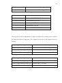
TABLE 7. Test combinations of Car Alarm System
4.1.5 Garage Door System
Among the three combined circuits from which the final circuit was made is the
garage door system circuit. Its main function is to simulate the workings of a
garage door when it is needed to be opened or closed using an electronic system.
The circuit uses switches as inputs and light and sound as outputs. The input
switches are the following:
PUSH BUTTON (PB)
FLIP SWITCH 1 (S1)
The push button trigger a temporary high state in the microcontroller pin to which
it is connected and the flip switch state indicates the first state of the garage door
either OPEN or CLOSED when it is first powered on.
24
The output indicators are the following:
GREEN Light Emitting Diode (D1)
GREEN Light Emitting Diode (D2)
GREEN Light Emitting Diode (D3)
BUZZER (SPK)
The front view of SADET shows more than the required components for the
testing of a garage door system but the required input and output components are
marked out as shown in Graph 15.
GRAPH 10. Garage Door System on front view
25
The functioning of the circuit was tested using:
1 -- PUSH BUTTON
1 -- FLIP SWITCHES
3 -- GREEN LED
1 -- BUZZER
4 -- 300Ω RESISITORS
2 -- 330KΩ RESISTORS
1 -- ARDUINO NANO MICROCONTROLLER
BREAD BOARD and CONNECTIONWIRE
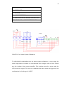
GRAPH 11. Garage Door System Schematics
To individually troubleshoot the garage door system schematics, a copy using the
same components was made on a breadboard, and a sample code was also loaded
into the Arduino Nano microcontroller. The switches served as inputs and the
LED and buzzer served as output. The test was conducted and the circuit was
approved for combination in the design of SADET.
26
GRAPH 12. Garage Door System prototype on Bread Board
4.1.6 Operation
A sample of the garage door system simulation code was uploaded into the
Arduino Nano microcontroller. With the Universal Serial Bus (USB) supplying the
5volts needed by the circuit, a testing process was performed.
Push button PB is used to place the necessary pin on the microcontroller on a
temporary high state. Flip switch S1 indicates the initial state of the door, high or
low for OPENED or CLOSED.
The corresponding microcontroller pins are
mapped as follows:
PUSH BUTTON (PB)
connected to Arduino Nano Digital Pin 2
FLIP SWITCH 1 (S1)
connected to Arduino Nano Digital Pin 3
27
The output from the combinations of input is indicated by setting various pins in
the microcontroller to high state. The output pins are set to the output device as
follows:
GREEN Light Emitting Diode (D1)
connected to Arduino Nano Digital Pin 10
GREEN Light Emitting Diode (D2)
connected to Arduino Nano Digital Pin 11
GREEN Light Emitting Diode (D3)
connected to Arduino Nano Digital Pin 12
BUZZER (SPK)
connected to Arduino Nano Digital Pin 13
On powering on the circuit, the state of flip switch S1 is read and the initial state of
the circuit either OPENED or CLOSED is observed and the corresponding light
emitting diode (LED) is powered on. The push button is used to initiate a change
of state, if pushed the output diode (LED) presently on is powered off and an
intermediate diode (LED) are powered on simultaneously with the buzzer. The
intermediate diode (LED) and the buzzer are powered off and the third diode
(LED) is powered on. This stays on until the push button is pushed again and the
process repeats itself in the reverse direction. Each output indicates a specific
warning:
GREEN Light Emitting Diode (D1)
indicates DOOR OPENED
GREEN Light Emitting Diode (D2)
indicates DOOR OPENING / CLOSING
GREEN Light Emitting Diode (D3)
indicates DOOR CLOSED
BUZZER (SPK)
audio output for door opening or closing.
4.1.7 Dice Rolling System
Among the three combined circuits from which the final circuit was made is the
dice rolling system circuit. It main function is to simulate a dice rolling process
28
electronically. The circuit uses a switch as inputs and a 7-segment light emitting
diode as outputs. The input switch is:
PUSH BUTTON (PB)
The push button triggers a temporary high state in the microcontroller pin to
which it is connected. The output indicator is:
7-SEGMENT Light Emitting Diode (7-SEG)
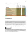
The front view of SADET shows more than the required components for the
testing of a dice rolling system but the required input and output components are
marked out as shown in Graph 18.
GRAPH 13. Dice Rolling System on front view
29
The functioning of the circuit was tested using:
1 -- PUSH BUTTON
7 -- 300Ω RESISITORS
1 -- 330KΩ RESISTORS
1 -- ARDUINO NANO MICROCONTROLLER
BREAD BOARD and CONNECTIONWIRE
GRAPH 14. Dice Rolling System Schematics
To individually troubleshoot the dice rolling system schematics, a copy using the
same components was made on a breadboard and a sample code was also loaded
into the Arduino Nano microcontroller. The switches served as inputs, and the 7SEGMENT LED served as output. The test was conducted and the circuit was
approved for combination in the design of SADET.
30
GRAPH 15. Dice Rolling System prototype on Bread Board
4.1.8 Operation
A sample of the dice rolling system simulation code was uploaded into the
Arduino Nano microcontroller. With the Universal Serial Bus (USB) supplying the
5volts needed by the circuit, a testing process was performed.
Push button PB is used to place the necessary pin on the microcontroller on a
temporary high state. The corresponding microcontroller pins are mapped as
follows:
PUSH BUTTON (PB)
connected to Arduino Nano Digital Pin 2
The output from the input is indicated by setting various pins in the
microcontroller to low state because the 7-SEG is a common cathode which means
all diodes (LEDs) are connected to a common pin (+) which in turn is connected to
31
5volts. Microcontroller pins are set to low to ensure a low potential difference with
respect to the 5volts high potential thus ensuring the flow of electricity through
the diode (LED). The output pins all combines to the functioning of the 7-SEG
diode (LED) and are set to the output device as follows:
7-SEG-a
connected to Arduino Nano Digital Pin 12
7-SEG-b
connected to Arduino Nano Analog Pins A0
7-SEG-c
connected to Arduino Nano Analog Pins A1
7-SEG-d
connected to Arduino Nano Analog Pins A2
7-SEG-e
connected to Arduino Nano Analog Pins A3
7-SEG-f
connected to Arduino Nano Analog Pins A4
7-SEG-g
connected to Arduino Nano Analog Pins A5
7-SEG-dp
not connected
7-SEG-+
connected to 5volt supply (common cathode)
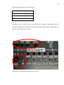
On powering on the circuit, all the diodes (LEDs) are set to HIGH rendering them
off. The push button provides temporary contact for creating a high state in the
input pin to initiate the generation of a random number which is displayed in the
7-SEG. The corresponding pins needed to form the number are set to LOW state
and others set to HIGH. The pin to LED arrangement is shown in Graph 21:
GRAPH 16. 7-Segment Display pins label
32
4.2 Embedded Software
In addition to creating a physical device using electronic components, a
complimentary code in C Language (Embedded C) must be written and uploaded
into the microcontroller before it can function. The function of the device is
exclusively decided by the code uploaded into it as the physical device serves as a
means to send in input into the code and display output of the code. The device’s
multiple inputs and outputs serve to give options and flexibility when writing the
code. The device has the capability to test any embedded software capable of
using any or all of the inputs as its inputs and any or all of the device outputs as
its outputs.
4.2.1 Arduino Integrated Development Environment (IDE)
Embedded software for Arduino microcontrollers are written and compiled using
the Arduino IDE (Integrated Development Environment). Arduino IDE software is
Open Source, which means everyone has access to it freely, and it can be
downloaded from Arduino webpage (http://arduino.cc/en/Main/Software). After
downloading the software, which comes as a Zip file (Arduino 1.0 at the time of
this material), it should be unzipped, copied to a safe location on the hard drive
and the file structure of the download preserved. Open the folder and double click
on the file named Arduino.exe, this will launch the Arduino IDE.
33
GRAPH 17. Arduino IDE
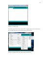
To test the connectivity of the Arduino IDE, a sample project can be loaded from a
list of sample code that was downloaded along with the IDE.
GRAPH 18. Arduino IDE when load example sketch (code)
34
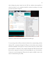
After loading the project sketch into the IDE, the Arduino microcontroller to
which the sketch is to be uploaded should be selected according to the steps
provided in the below Graph 24.
GRAPH 19. Arduino IDE when selecting microcontroller type
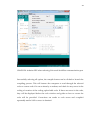
To access the port that will be used by the Arduino kit in communicating with the
Arduino IDE, a connection through the USB port to the Arduino microcontroller
should be established. This option can only be selected when the Arduino Nano
microcontroller is connected to the computer through the USB (Universal Serial
Bus) and the computer has detected and acknowledges the use of the interfaces.
Connection is made through the USB port but the option available comes in the
form of communication port (COM).
35
GRAPH 20. Arduino IDE when selecting Universal Serial Bus communication port
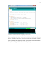
Successfully selecting all option, the compile button can be clicked to launch the
compiling process. This will instruct the computer to read through the selected
code or custom code if it was written by a student, and check for any errors in the
coding of creation of the coding upload able code. If there are errors in the code,
they will be displayed below the code window and guide on how to correct the
code will be provided. Corrections are made to code errors and compiled
repeatedly until a 100% success is obtained.
36
GRAPH 21. Arduino IDE when compiling a sketch (code)
Upon completing, the upload button can be clicked to launch the uploading
process. Uploading is the process whereby the written and successfully compiled
code is transferred into the memory of the microcontroller (in this case Arduino
Nano). Successfully uploaded code is indicated by a beep.
37
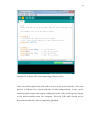
GRAPH 22. Arduino IDE when uploading a sketch (code)
After successful upload, the code will be active in the microcontroller. The same
process is followed for custom software created independently. Codes can be
tested using the inputs and outputs configured in the codes and the power supply
to the microcontroller from the computer. Thus the USB cable should not be
disconnected after the code is completely uploaded.
38
4.2.2 Programming Arduino with C Language
The magic happens when you press the button that upload the program to the
board; the code you have written is translated into C language, that is normally
quite hard to use for a beginner, and passed on to the avr-gcc compiler (an
important piece of open-source software) that makes the ultimate translation into
the language understood by the microcontroller. (Banzi 3rd release, 9.)
Arduino libraries for interface access:
The Arduino coding begins with defining the pins and attributing them to variable
names used in the code such as;
#define BUTTON 2 // Push button connected to digital pin 2
for digital pins, pin numbers are directly written,
#define LED A0 // LED connected to Analog pin A0
for analog pins, pin numbers are written are letter A
next is a two block structure enclosing several statements:
void setup() { preparing statements; }
preparation statements such as:
pinMode(pin, mode);
pinMode(LED, OUTPUT); // sets the analog pin as output
pinMode(BUTTON, INPUT); // sets the digital pin as input
and void loop() { execution Statements; }
39
execution Statements such as:
digitalRead(pin);
value = digitalRead(BUTTON); // read input value and store it by checking if state
is HIGH or LOW
digitalWrite(pin, value);
digitalWrite(LED, HIGH); // write to output LED by setting it to HIGH
analogRead(pin);
value = analogRead(A0); // read input value and store it
analogWrite(pin, value);
analogWrite(LED, HIGH); // write to output LED by setting it to HIGH
note: digital signal can be written to analog pins.
other useful library functions:
randomSeed(seed)
randomSeed(analogRead(7)); // to initial a new sequence of random value
random(max)
random(min, max)
random(1,7); // random value generation
delay(millisecond);
delay(10); // create delay in continuation
millis();
40
value = millis(); //return the number of milliseconds since Arduino board began
running the current program as an unsigned long value.
min(x,y);
value = min(value, 50);// calculate and return the minimum of two values.
max(x,y);
value = max(value, 50); // calculate and return the maximum of two values.
All C Language constructs e.g:
int val = 0; //variable declaration
if () {} // if statement
if () {} … else // if else statement
for(){}//for loop
switch (x){ case 1: statements;
default: }
while {} //while statement
do{} while() //do..while statement
char functions(){}//function statement
datatypes: byte, int, long, float.
41
4.2.3 Sample Code for Car Alarm System
// Example Turn on LED D1 on pin D10, LED D2 on pin D11 and LED D3 on pin
// D12 when the buttons SW1 – SW6 on pins D4 – D9 is pressed according to Table
// 6 on page 22. Also makes sound from BUZZER connected to pin D13 when
// LEDs D1, // D2, D3 are on
#define LIGHT_ALARM 10 // LIGHT_ALARM connected to digital pin 10
#define KEYS_ALARM 11 // KEYS_ALARM connected to digital pin 11
#define BELT_ALARM 12 // BELT_ALARM connected to digital pin 12
#define BUZZER 13 // Speaker connected to digital pin 13
#define DOOROPEN 4 // INPUT connected to digital pin 2
#define ENGINERUNNING 5 // INPUT connected to digital pin 3
#define KEYSINPLACE 6 // INPUT connected to digital pin 3
#define LIGHTSON 7 // INPUT connected to digital pin 3
#define BELTOPEN 8 // INPUT connected to digital pin 3
#define DRIVERSITTING 9 // INPUT connected to digital pin 3
void setup() {
pinMode(LIGHT_ALARM, OUTPUT); // sets the digital pin as output
pinMode(KEYS_ALARM, OUTPUT); // sets the digital pin as output
pinMode(BELT_ALARM, OUTPUT); // sets the digital pin as output
pinMode(BUZZER, OUTPUT); // sets the digital pin as output
42
pinMode(DOOROPEN, INPUT); // sets the digital pin as input
pinMode(ENGINERUNNING, INPUT); // sets the digital pin as input
pinMode(KEYSINPLACE, INPUT); // sets the digital pin as input
pinMode(LIGHTSON, INPUT); // sets the digital pin as input
pinMode(BELTOPEN, INPUT); // sets the digital pin as input
pinMode(DRIVERSITTING, INPUT); // sets the digital pin as input }
void loop() {
/* lights reminder */
if (isLightsOn() && (!isEngineRunning()) && isDriverDoorOpen() )
setLightsAlarmOn();
else setLightsAlarmOff();
/* key reminder */
if (isKeyInPlace() && (!isEngineRunning()) && isDriverDoorOpen())
setkeyALarmOn();
else setkeyALarmOff();
/*if seat belt is not fastend do alarm */
if (isDriverSitting() && isBeltOpen() && isKeyInPlace()) setBeltAlarmOn();
else setBeltAlarmOff(); }
///////////// FUNCTIONS ////////////////////////////////////////
unsigned char isLightsOn() { if (digitalRead(LIGHTSON) == HIGH) return HIGH;
43
else return LOW; }
unsigned char isEngineRunning() { if (digitalRead(ENGINERUNNING) == HIGH)
return HIGH;
else return LOW; }
unsigned char isDriverDoorOpen() { if (digitalRead(DOOROPEN) == HIGH)
return HIGH;
else return LOW;}
unsigned char isKeyInPlace() { if (digitalRead(KEYSINPLACE) == HIGH)
return HIGH;
else return LOW; }
unsigned char isDriverSitting() { if (digitalRead(DRIVERSITTING) == HIGH)
return HIGH;
else return LOW; }
unsigned char isBeltOpen() { if (digitalRead(BELTOPEN) == HIGH) return HIGH;
else return LOW; }
void setLightsAlarmOn() { digitalWrite(LIGHT_ALARM, HIGH);//set LED on
digitalWrite(BUZZER, HIGH);//set buzzer on }
void setLightsAlarmOff() { digitalWrite(LIGHT_ALARM, LOW);//set LED OFF
digitalWrite(BUZZER, LOW);//set buzzer OFF }
void setkeyALarmOn() { digitalWrite(KEYS_ALARM, HIGH); //set LED on
digitalWrite(BUZZER, HIGH);//set buzzer on }
void setkeyALarmOff() { digitalWrite(KEYS_ALARM, LOW); //set LED on
44
digitalWrite(BUZZER, LOW);//set buzzer on }
void setBeltAlarmOn() {digitalWrite(BELT_ALARM, HIGH); // led is Off now
digitalWrite(BUZZER, HIGH);//set buzzer on }
void setBeltAlarmOff() { digitalWrite(BELT_ALARM, LOW);// 5volt led is on
digitalWrite(BUZZER, LOW);//set buzzer on }
4.2.4 Sample Code for Garage Door System
// Example Turn on LED on pin D10, LED on pin D11 and LED on pin D12
// when the button on pin D2 is pressed. Also makes sound connect to pin D13
// when LED on pin D11 is on. Switch on pin D3 indicate initial state of circuit
// and keep it on after it is released. Including simple de-bouncing
#define OPENEDLIGHT 10 // OPENEDLIGHT connected to digital pin 10
#define O_C_LIGHT 11 // O_C_LIGHT connected to digital pin 11
#define CLOSEDLIGHT 12 // CLOSEDLIGHT connected to digital pin 12
#define BUZZER 13 // Speaker connected to digital pin 13
#define DOORSWITCH 2 // INPUT connected to digital pin 2
#define DOOR_STATE 3 // FIRST STATE INPUT connected to digital pin 3
int val = 0; // val will be used to store the state of the input pin
int state_init; // store the first state of the device
45
int state;
// holds the changing state of the device
const int CLOSED = 1; // closed state
const int OPENING = 2; // opening state
const int CLOSING = 3;// closing state
const int OPENED = 4;// opened state
void setup() { pinMode(OPENEDLIGHT, OUTPUT);//sets the digital pin as output
pinMode(O_C_LIGHT, OUTPUT); // sets the digital pin as output
pinMode(CLOSEDLIGHT, OUTPUT); // sets the digital pin as output
pinMode(BUZZER, OUTPUT); // sets the digital pin as output
pinMode(DOORSWITCH, INPUT); // sets the digital pin as input
pinMode(DOOR_STATE, INPUT); // sets the digital pin as input
state_init = digitalRead(DOOR_STATE); //reads device first state
if (state_init == HIGH)state = CLOSED; //determines device first state
else state = OPENED; }
void loop() {
// check if there was a transition
if (state == CLOSED) { digitalWrite(O_C_LIGHT, LOW); // turn LED ON
digitalWrite(BUZZER, LOW); //speaker off
digitalWrite(CLOSEDLIGHT, HIGH); // turn LED ON
for(;;) { val = digitalRead(DOORSWITCH); // read input value and store it
46
if(val == HIGH){state = OPENING; digitalWrite(CLOSEDLIGHT, LOW);break;}}
delay(1000); }
if (state == OPENING) { digitalWrite(O_C_LIGHT, HIGH); // turn LED ON
digitalWrite(BUZZER, HIGH); state = OPENED; delay(1000); }
if (state == CLOSING) { digitalWrite(O_C_LIGHT, HIGH); // turn LED ON
digitalWrite(BUZZER, HIGH); state = CLOSED; delay(1000); }
if (state == OPENED) { digitalWrite(O_C_LIGHT, LOW); // turn LED ON
digitalWrite(BUZZER, LOW); digitalWrite(OPENEDLIGHT, HIGH);
for(;;) { val = digitalRead(DOORSWITCH); // read input value and store it
if(val == HIGH){state = CLOSING; digitalWrite(OPENEDLIGHT, LOW);break;}}
delay(1000); } }
4.2.5 Sample Code for Dice Simulation System
// Example DICE ROLLING CODE that Turns on seven segment display
#define 7_SEGMENTa 12 // 7_SEGMENTa connected to digital pin 12
#define 7_SEGMENTb A0 // 7_SEGMENTb connected to Analog pin A0
#define 7_SEGMENTc A1 // 7_SEGMENTc connected to Analog pin A1
#define 7_SEGMENTd A2 // 7_SEGMENTd connected to Analog pin A2
#define 7_SEGMENTe A3 // 7_SEGMENTe connected to Analog pin A3
47
#define 7_SEGMENTf A4 // 7_SEGMENTf connected to Analog pin A4
#define 7_SEGMENTg A5 // 7_SEGMENTg connected to Analog pin A5
#define ROLLDICE 2 // INPUT connected to digital pin 2
int val = 0; // val will be used to store the state of the input pin
int old_val = 0; // this variable stores the previous value of "val"
int result = 0; // holds the random value generated
void setup() { pinMode(7_SEGMENTa, OUTPUT); // sets the digital pin as output
//sets the Analog pins as output//
pinMode(7_SEGMENTb, OUTPUT); pinMode(7_SEGMENTc, OUTPUT);
pinMode(7_SEGMENTd, OUTPUT); pinMode(7_SEGMENTe, OUTPUT);
pinMode(7_SEGMENTf, OUTPUT); pinMode(7_SEGMENTg, OUTPUT);
pinMode(ROLLDICE, INPUT); // sets the digital pin as input
randomSeed(analogRead(7)); // to initial a new sequence of random value
//initial state of display
digitalWrite(7_SEGMENTa, HIGH); digitalWrite(7_SEGMENTb, HIGH);
digitalWrite(7_SEGMENTc, HIGH); digitalWrite(7_SEGMENTd, HIGH);
digitalWrite(7_SEGMENTe, HIGH); digitalWrite(7_SEGMENTf, HIGH);
digitalWrite(7_SEGMENTg, HIGH); }
void loop() { val = digitalRead(ROLLDICE); // read input value and store it
// check if ROLLDICE pressed
48
if ((val == HIGH) && (old_val == LOW)) { result = random(1,7); // random value
//OUTPUT TO 7_SEGMENT
switch (result) { case 1:
digitalWrite(7_SEGMENTa, HIGH); digitalWrite(7_SEGMENTb, LOW);
digitalWrite(7_SEGMENTc, LOW); digitalWrite(7_SEGMENTd, HIGH);
digitalWrite(7_SEGMENTe, HIGH); digitalWrite(7_SEGMENTf, HIGH);
digitalWrite(7_SEGMENTg, HIGH); break;
case 2:
digitalWrite(7_SEGMENTa, LOW); digitalWrite(7_SEGMENTb, LOW);
digitalWrite(7_SEGMENTc, HIGH); digitalWrite(7_SEGMENTd, LOW);
digitalWrite(7_SEGMENTe, LOW); digitalWrite(7_SEGMENTf, HIGH);
digitalWrite(7_SEGMENTg, LOW); break;
case 3:
digitalWrite(7_SEGMENTa, LOW); digitalWrite(7_SEGMENTb, LOW);
digitalWrite(7_SEGMENTc, LOW); digitalWrite(7_SEGMENTd, LOW);
digitalWrite(7_SEGMENTe, HIGH); digitalWrite(7_SEGMENTf, HIGH);
digitalWrite(7_SEGMENTg, LOW); break;
case 4:
digitalWrite(7_SEGMENTa, HIGH); digitalWrite(7_SEGMENTb, LOW);
digitalWrite(7_SEGMENTc, LOW); digitalWrite(7_SEGMENTd, HIGH);
49
digitalWrite(7_SEGMENTe, HIGH); digitalWrite(7_SEGMENTf, LOW);
digitalWrite(7_SEGMENTg, LOW); break;
case 5:
digitalWrite(7_SEGMENTa, LOW); digitalWrite(7_SEGMENTb, HIGH);
digitalWrite(7_SEGMENTc, LOW); digitalWrite(7_SEGMENTd, LOW);
digitalWrite(7_SEGMENTe, HIGH); digitalWrite(7_SEGMENTf, LOW);
digitalWrite(7_SEGMENTg, LOW); break;
case 6:
digitalWrite(7_SEGMENTa, LOW); digitalWrite(7_SEGMENTb, HIGH);
digitalWrite(7_SEGMENTc, LOW); digitalWrite(7_SEGMENTd, LOW);
digitalWrite(7_SEGMENTe, LOW); digitalWrite(7_SEGMENTf, LOW);
digitalWrite(7_SEGMENTg, LOW); break;
default:
digitalWrite(7_SEGMENTa, HIGH); digitalWrite(7_SEGMENTb, HIGH);
digitalWrite(7_SEGMENTc, HIGH); digitalWrite(7_SEGMENTd, HIGH);
digitalWrite(7_SEGMENTe, HIGH); digitalWrite(7_SEGMENTf, HIGH);
digitalWrite(7_SEGMENTg, HIGH); break; } }
old_val = val; delay(10); /*de-bouncing control*/ }
50
5 USAGE OF THE EMBEDDED KIT
The architecture of the embedded kit (SADET) is focused on its usage for testing
any embedded software. The device created has enough inputs and outputs so
that it can be used to demonstrate and test most examples used in present COUAS
embedded software course. The device has multiple inputs connected to specific
pins on the Arduino Nano and the outputs are also connected to specific pins on
the Arduino. These are fixed connections and the use of the input signals and the
output signals in the code must be mapped to these specific pins.
The hardware device (SADET) will be provided and the pins connection should be
studied from previous chapters. The knowledge of the pin connections is needed
when coding. With good understanding of the pin connections, the Arduino IDE
should be launched if downloaded already else download and configure it as
explained in previous chapter.
A new project is initiated with the start a new project (sketch) icon or from the
Arduino IDE menu and followed by a code that meets the function to be
demonstrated with SADET. The steps explained in the previous chapter on how to
create and load codes (sketches) into the Arduino microcontroller gives a detailed
description. Completely compiled and uploaded code can be tested with SADET
still connected to the USB port of the computer as it is the source of the 5volts
needed to power the circuit.
Testing a code with SADET involves sending input from the input component
defined in the code and observing the output from the output component defined
51
in the code either diode (LED), buzzer (sound) or 7-Segment display. If output
display is as expected, the code works perfectly else the code edited, compiled and
uploaded into SADET until the desired output is obtained.
5.1 From Connection to Code Simulation
The complete understanding of how the Arduino Nano working in line with other
circuit components (input and output) is relevant to using SADET. It is not a
complex process as it involves setting a pin to HIGH or LOW state. 5volts create a
HIGH state source point and GND (ground) creates a LOW state end point. The
basic law of electricity which states that electricity flow from a point of high
potential HIGH to a point of low potential LOW is applicable here. The USB cable
connected to the computer supplies the 5volts through one of its pins and a
ground connection (GND) through another thus making it very important and
should stay connected to the computer while operating SADET.
A written and compiled code (sketch) should be uploaded into the Arduino Nano
microcontroller and a simulation of the code performed using SADET. This
involves sending described input signals in the code with the input component
and observing through audio or visual the output component according to the
code specification.
52
6 CONCLUSION
The aim of this thesis is to create a single embedded kit with an Arduino Nano
capable of simulating and troubleshooting any embedded software. An embedded
kit (SADET) was created from the combination of a car alarm, garage door and
dice rolling system. SADET is capable of simulating and troubleshooting any
embedded software that can adapt to its system’s eight input and five output
components.
SADET’s basic function is to test and demonstrate any embedded software whose
input and output requirement can be met by SADET. Projects (sketches) are
coded, compiled and uploaded to SADET using the Arduino IDE through a USB
cable connecting SADET to the computer. After uploading, the project is tested
using input components to send input signal and observing the output
components for proper functioning. If needed the coding errors are corrected in
IDE and the process is repeated until the functioning observed by testing in
SADET is what is wanted.
All projects (sketches) needed for the operational testing of the circuits from which
SADET was made were coded, compiled and uploaded individual into SADET.
The required input from the input components were sent in and used successfully
and the desired output from the output component where observed.
53
Arduino Nano is an embedded system that has pins to which any input or output
component can be connected. This leaves room for the improvement of SADET
with components like a potentiometer if a steady decrease in output voltage is
needed, a proximity sensor switch if a non-contact input is required, infra-red
sensor switch if a remote control mechanism is needed. The improvement of
SADET is vast and only limited by the imagination of the designer and also the
requirement for the circuit to be simulated.
The project (sketch) coding is almost the same but with a few more Arduino
libraries to be learnt and the whole of C Language libraries at the programmer´s
disposal.
54
REFERENCES
Banzi, M. 2010. Getting Started with Aduino. Third release. California, USA:
Makebooks.
Brian, E. 2007. Arduino programming notebook. First edition. California, USA:
Creative commons.
Component image 2012. 7segment display. Available:
http://www.mikrocontroller-rojekte.de/Mikrocontroller/7Segment/7Segment.html.
Accessed 1 April 2012.
Component image 2012. Light Emitting Diode. Available:
http://ca.digikey.com/1/3/indexb1598.html. Accessed 1 April 2012.
Component image 2012. Buzzer. Available:
http://www.rapidonline.com/Electrical-Power/Miniature-electronic-buzzer-83008.
Accessed 1 April 2012.
Component image 2012. 7segment circuit. Available:
http://parts.digikey.com/1/parts-kws/7-segment-displays. Accessed 1 April 2012.
Course material 2012. Embedded software. Available:
https://cou171.wikidot.com/embedded:embedded-software. Accessed 1 April
2012.
Jamieson, P. Arduino for Teaching Embedded Systems. Miami University, USA.
McRoberts, M. 2009. Arduino starter kit manual. A complete beginner’s guide to
the Arduino. First edition. Miami, USA: Earthshine electronics.
Vahid, F. and Givargis, T. Timing is Everything - Embedded Systems Demand
Early Teaching of Structured Time-Oriented Programming. Department of
Computer and Engineering, University of California, USA